

Page 1

XI882
EXCEL 500 OPEN SYSTEM
USER GUIDE
® U.S. Registered Trademark EN2B-0615GE51 R0709
Copyright © 2009 Honeywell Inc.
All Rights Reserved
Page 2

XI882 USER GUIDE
Software License Advisory This document supports software that is proprietary to Honeywell Inc. and/or to third
Trademark Information Echelon, LON, L
party software vendors. Before software delivery, the end user must execute a
software license agreement that governs software use. Software license agreement
provisions include limiting use of the software to equipment furnished, limiting
copying, preserving confidentiality, and prohibiting transfer to a third party.
Disclosure, use, or reproduction beyond that permitted in the license agreement is
prohibited.
ONMARK, LONWORKS, LonBuilder, NodeBuilder, LonManager,
LonTalk, LonUsers, LonPoint, Neuron, 3120, 31701, the Echelon logo, the LonMark
logo, and the LonUsers logo are trademarks of Echelon Corporation registered in
the United States and other countries. LonLink, LonResponse, LonSupport, and
LonMaker are trademarks of Echelon Corporation.
BACnet is a registered trademark of the American Society of Heating, Refrigerating
and Air-Conditioning Engineers, Inc.
Microsoft and Windows are registered trademarks of Microsoft Corporation. Other
brands and their products are trademarks or registered trademarks of their
respective holders and should be noted as such.
EN2B-0615GE51 R0709 2
Page 3

USER GUIDE XI882
CONTENTS
INTRODUCTION................................................................................................................. 7
GENERAL..........................................................................................................................................................7
MANUAL ORGANIZATION...............................................................................................................................8
GETTING STARTED...........................................................................................................9
CONNECT XI882 TO EXCEL WEB OR EXCEL 500 FAMILY CONTROLLER.................................................9
PREREQUISITES/RECOMMENDATIONS FOR USING XI882.......................................................................10
USB MEMORY DEVICE USE WITH XI882......................................................................................................11
STARTUP SCREENS ......................................................................................................................................13
Configure XI882 for Excel Web Controller...........................................16
NETWORK SETTINGS....................................................................................................................................17
Configure XI882 for Excel 500 Family Controllers..............................23
OPERATE EXCEL 500 FAMILY CONTROLLER............................................................. 24
OPERATING ICONS........................................................................................................................................24
ONLINE/OFFLINE CONTROLLER STATUS INDICATION.............................................................................25
COLUMN WIDTH ADJUSTMENT....................................................................................................................25
SORT LINES OPTION.....................................................................................................................................26
ENTER DATA ..................................................................................................................................................26
XI882 CONNECTED TO AN APPLICATIONLESS CONTROLLER................................................................27
HOME...............................................................................................................................................................28
BUSWIDE ACCESS.........................................................................................................................................30
LOGIN/LOGOUT..............................................................................................................................................31
CONFIGURATION...........................................................................................................................................37
TRENDING.......................................................................................................................................................48
ALARMS..........................................................................................................................................................57
INFORMATION................................................................................................................................................61
CONTROLLER.................................................................................................................................................63
DATAPOINTS..................................................................................................................................................71
PARAMETERS ................................................................................................................................................74
TIME PROGRAMS...........................................................................................................................................78
FAST ACCESS LIST CONFIGURATION........................................................................................................84
3 EN2B-0615GE51 R0709
Page 4

XI882 USER GUIDE
POWER-FAIL, SOFTWARE UPDATE AND WIN CE BEHAVIORS - FOR A PHYSICALLY (LOCAL)
CONNECTED CONTROLLER......................................................................................................................... 89
POWER-FAIL, SOFTWARE UPDATE AND WIN CE BEHAVIORS - FOR A BUS-WIDE CONNECTED
CONTROLLER ................................................................................................................................................ 89
OPERATE EXCEL WEB...................................................................................................90
HOME PAGE DESCRIPTION AND BASIC FUNCTIONS...............................................................................90
Home Page Description........................................................................90
Basic Functions..................................................................................... 92
LOGIN TO XI882..............................................................................................................................................93
LOGOUT FROM XI882.................................................................................................................................... 94
CHANGE CONTEXT........................................................................................................................................ 94
CONFIGURATION........................................................................................................................................... 95
Configure Display.................................................................................. 95
Configure Sort Orders........................................................................... 96
Configure Cycle Time ...........................................................................99
View/Reset LON Statistics.................................................................. 100
Configure Date & Time........................................................................ 101
View / Configure Communication Settings.......................................103
User Administration............................................................................ 108
DISPLAY PROJECT INFORMATION............................................................................................................ 112
DISPLAY CONTROLLER INFORMATION.................................................................................................... 114
DISPLAY PLANT INFORMATION.................................................................................................................116
View Control Loop Information.......................................................... 118
FAST ACCESS LISTS................................................................................................................................... 121
Create New Fast Access List.............................................................. 121
Modify Fast Access List...................................................................... 128
Delete Fast Access List ...................................................................... 129
Show/Modify Point/Parameter From within Fast Access List......... 130
SCHEDULES.................................................................................................................................................131
CALENDARS................................................................................................................................................. 140
DATAPOINTS................................................................................................................................................ 144
View Schedules................................................................................... 131
Edit Schedule....................................................................................... 132
View Calendars.................................................................................... 141
View Calendar Details.........................................................................141
View Referenced Schedules............................................................... 143
View Datapoint List............................................................................. 144
View / Edit Datapoint Details..............................................................146
General Procedure.............................................................................. 146
View General Properties..................................................................... 147
View / Edit Values................................................................................ 148
View Status Properties ....................................................................... 149
View Alarm........................................................................................... 150
View Miscellaneous Priorities............................................................ 152
View / Edit Command Priorities ......................................................... 153
Show Datapoints in Hand...................................................................154
PARAMETERS.............................................................................................................................................. 155
EN2B-0615GE51 R0709 4
View Parameters List .......................................................................... 155
View Parameter Info / Change Parameter Value............................... 156
Page 5

USER GUIDE XI882
ALARMS........................................................................................................................................................158
View Datapoints in Alarm....................................................................158
View System Alarms ........................................................................... 158
SERVICE FUNCTIONS...................................................................................................165
SOFTWARE CONTAINED.............................................................................................................................165
INITIAL STEPS..............................................................................................................................................165
HOW TO IDENTIFY SOFTWARE VERSIONS...............................................................................................167
How to identify the XI882 Application Software Version..................167
How to identify the WIN CE Application Starter Version..................167
How to identify the WIN CE Image Version.......................................169
How to identify the WIN CE Bootloader Version............................... 171
HOW TO UPDATE SOFTWARE....................................................................................................................172
Update XI882 Application Software....................................................172
Update Windows CE Image and Bootloader.....................................174
Update the Appstarter.exe.................................................................. 179
SETUP / CHANGE WINDOWS CE CONFIGURATION................................................................................. 180
5 EN2B-0615GE51 R0709
Page 6

XI882 USER GUIDE
EN2B-0615GE51 R0709 6
Page 7
USER GUIDE XI882
INTRODUCTION
General
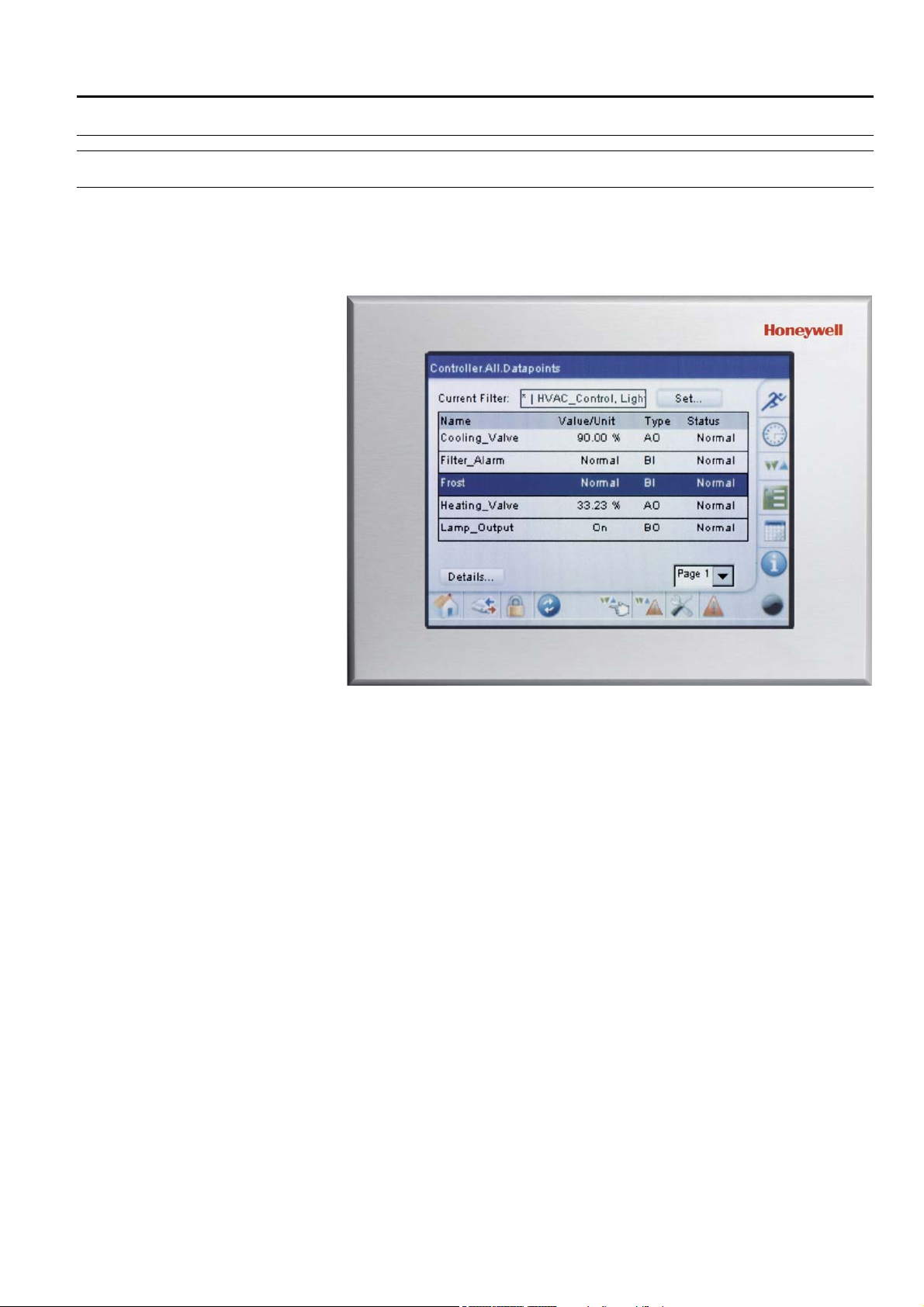
The XI882 operator interface, in the following simply named XI882, allows operating
controllers belonging to both the Excel 500 family (e.g. Excel 50/80/100/500//800)
and to the Excel Web family (XL1000C or later versions only).
XI882 automatically recognizes the connected controller type (Excel Web family or
Excel 500 family) and automatically starts the correct form of communication.
Fig. 1. XI882 operator interface
The XI882 is operated using the finger or the stylus provided as an accessory with
every device. You can navigate through the screens, selecting options and making
inputs by tapping with your finger or with the stylus.
When using the XI882 as the operator interface for an Excel Web controller, it will
display only the web pages of the Excel Web controller. When using it for an Excel
500 family controller, only the operation pages for the Excel 500 family will be
displayed.
Controller Models XI882 can communicate with Excel 500 family controllers and with Excel Web
controllers.
XI882 can operate the controller it is connected to, and any controller which is
connected on the same bus (bus-wide operation).
NOTE: The Excel 500 family of controllers must have up-to-date software that
includes the bus-wide access mode feature for XI882.
Bus-wide operation XL50 / 100 / 500 / 800
When operating on a LON-Bus in bus-wide mode, controllers and front-ends (EBI)
will be displayed in the bus-wide controller selection list box.
Upon selection of EBI, the Excel Touch generates an error message, and once this
error message is confirmed by the user, Excel Touch will fall-back to the local
controller home screen.
7 EN2B-0615GE51 R0709
Page 8

XI882 USER GUIDE
Manual Organization
Purpose This manual explains how to connect and operate the XI882 for the Excel 500 family
controllers and Excel Web controller operation.
Organization This manual is divided into the following sections including this introductory section.
The “Introduction” section briefly describes the XI882 MMI.
The “Getting Started” section describes:
• Connecting XI882 to Excel 500 family controllers and Excel Web family
controllers
• XI882 Startup screens
• Configuring XI882 for Excel 500 family controllers and Excel Web family
controllers
The “Operate Excel 500 Family Controllers” section describes:
• Operating Icons
• Home page and Controller Status Indication
• Login/Logout procedure
• Bus-wide Access functionality
• Configuration settings
• Information display
• Operation of Excel 500 Family Controllers applying particular functions such
as:
− Alarms
− Controller
− Datapoints
− Parameters
− Time Programs
− Fast Access Lists
− Trending
The “Operate Excel Web” section describes:
• Home page and Basic functions
• Login/Logout procedure
• Change Context (Bus-wide Access functionality)
• Configuration settings
• Information display (project, controller, pant)
• Operation of Excel 500 Family Controllers applying particular functions such
as:
− Alarms
− Controller
− Datapoints
− Parameters
− Schedules
− Calendars
− Fast Access Lists
The “Service Functions” section describes:
• service functions that allow updating the application software of the XI882,
and setting up and changing the Windows CE configuration.
EN2B-0615GE51 R0709 8
Page 9

USER GUIDE XI882
GETTING STARTED
Getting started includes the following sections:
• Connect XI882 to Excel Web or Excel 500 family controller
• Startup screens
• Configure XI882
Connect XI882 to Excel Web or Excel 500 Family Controller
All connections are explained in the mounting instructions MU1B-0387GE51.
Disconnected Controller When disconnecting XI882 from the controller,
re-connecting it to the controller.
will be displayed correctly.
Only this will ensure that the C-Bus number
it must be power cycled before
9 EN2B-0615GE51 R0709
Page 10

XI882 USER GUIDE
Prerequisites/Recommendations for using XI882
1. In order to allow for bus-wide operation, the controller to which XI882 is
XL50 -> 2.06.14
XCL5010 -> 2.06.14
XC5010C -> 2.06.14
XL100C -> 2.06.14
XCL8010A -> 3.01.03
2. If a firmware update is required, this can be done with CARE or Excel Online.
3. Ensure that all controllers connected on the C-Bus are powered up and their
4. Ensure that XI882 is properly connected before powering it up. This will allow
5. Operate the XI882 screen with the stylus provided or with your finger.
6. The touch screen should be calibrated before operating any other functionalities
7. If the controller Auto detection mechanism does not work the first time, then tap
8. If you want to disconnect the XI882 from a controller and connect it to a new
9.
connected needs to be upgraded to at least the version mentioned below:
XI882 can be used to upgrade the controller firmware for the controller it is
directly connected to. (After this controller is updated, firmware update can be
done bus-wide through this controller.)
applications are running properly before powering up XI882 connected to any
controller on the C-Bus. Use Excel Online to ensure proper functionality of the
controllers.
automatic connection to the controller.
Do NOT use sharp devices like screwdrivers!
of the product.
For Excel 500 family operation this can be done by calling up the configuration
screen after going online. See section “Configuration”
For Excel Web operation this can be done either in the start-up operation which
comes up after power is connected, or by calling up the configuration screen
after being online. See section “Configuration”
on the Refresh icon in the toolbar to detect the controller.
controller having the same controller number (assuming that both controllers do
not reside on the same C-Bus) you should delete the previously created fast
access lists of the first controller before connecting it to the new controller.
Otherwise XI882 will display the fast access lists referring to the old controller,
which will not match.
Memory sticks must be formatted before use in FAT (no FAT32)
EN2B-0615GE51 R0709 10
Page 11
USER GUIDE XI882
USB Memory Device Use with XI882
NOTE: This section applies to Excel 500 Family Controllers only.
The XI882 has two USB ports for connecting a USB memory device to it in order to
upload/download applications, download firmware and import parameter files etc.
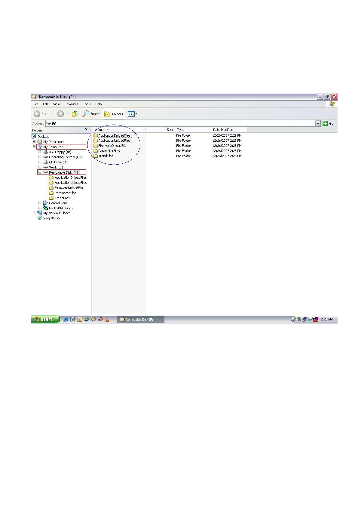
The USB memory device should have the directory structure as shown below. If this
structure is not present in the device, you have to create it using a PC.
Fig. 2. Directory Structure required in the memory device
The following folders should be present in the memory device:
ApplicationUploadFiles This folder is for uploading the application from the controller to the memory device.
Whenever an application is uploaded, it will be stored in this directory by default. If
you want to store the application in other directories, then you must create Subdirectories under this directory.
ApplicationDnloadFiles This folder is for downloading the application from the memory device to the
controller. It is recommended to create a sub-directory under this folder and copy all
files related to the specific controller application in it.
FirmwareDnloadFile This folder is for downloading firmware from the memory device into the controller.
You can create different folders for different firmware of different controllers under
this folder and store firmware files in the same.
ParameterFiles This folder is for importing the parameter information from parameter files of any
specific application. You should copy parameter files generated with CARE in this
directory and import the same in XI882.
11 EN2B-0615GE51 R0709
Page 12

XI882 USER GUIDE
TrendFiles This folder is for storing the trending information on the memory device. All the data
recorded during trend recording process is directly stored on the memory device. It
is mandatory to have the USB memory device connected to the XI882 in order to
use trending functionality.
EN2B-0615GE51 R0709 12
Page 13

USER GUIDE XI882
Startup Screens
Powering up XI882 On successfully powering up XI882 (for connections, see XI882 mounting
instructions MU1B-0387GE51, the XI882 MMI will display the Honeywell logo on the
screen as shown below. This screen will appear for approximately 20 sec.
Fig. 3. Startup screen with Honeywell logo
Next, the XI882 will try to detect the Excel 500 family controller and Excel Web
controller. In case of the Excel Web controller, XI882 will try to find the Excel Web
controller by pinging the previously stored IP address of the Excel Web controller.
During this time, it will show the auto detection message as shown below. This
screen has a time-out of 1 min.
AUTODETECTION
MESSAGE
Fig. 4. Auto detection message
Depending on the detection of the controller connected to the XI882, there
are four possible scenarios:
Case 1: XI882 detects an Excel 500 family controller only.
Case 2: XI882 detects an Excel Web controller only.
Case 3: XI882 detects both an Excel 500 family controller and an Excel Web
controller.
13 EN2B-0615GE51 R0709
Page 14
XI882 USER GUIDE
Case 1 On successful detection of an Excel 500 family controller by XI882, the
Case 4: XI882 does not detect any controller.
screen below will be displayed. You are directed automatically towards the
homepage of the Excel 500 family controller, which is the fast access list
overview.
Fig. 5. Excel 500 mode of operation home screen
For detailed instructions on operating an Excel 500 family controller, please refer to
the “Operate Excel 500 Family Controller” section.
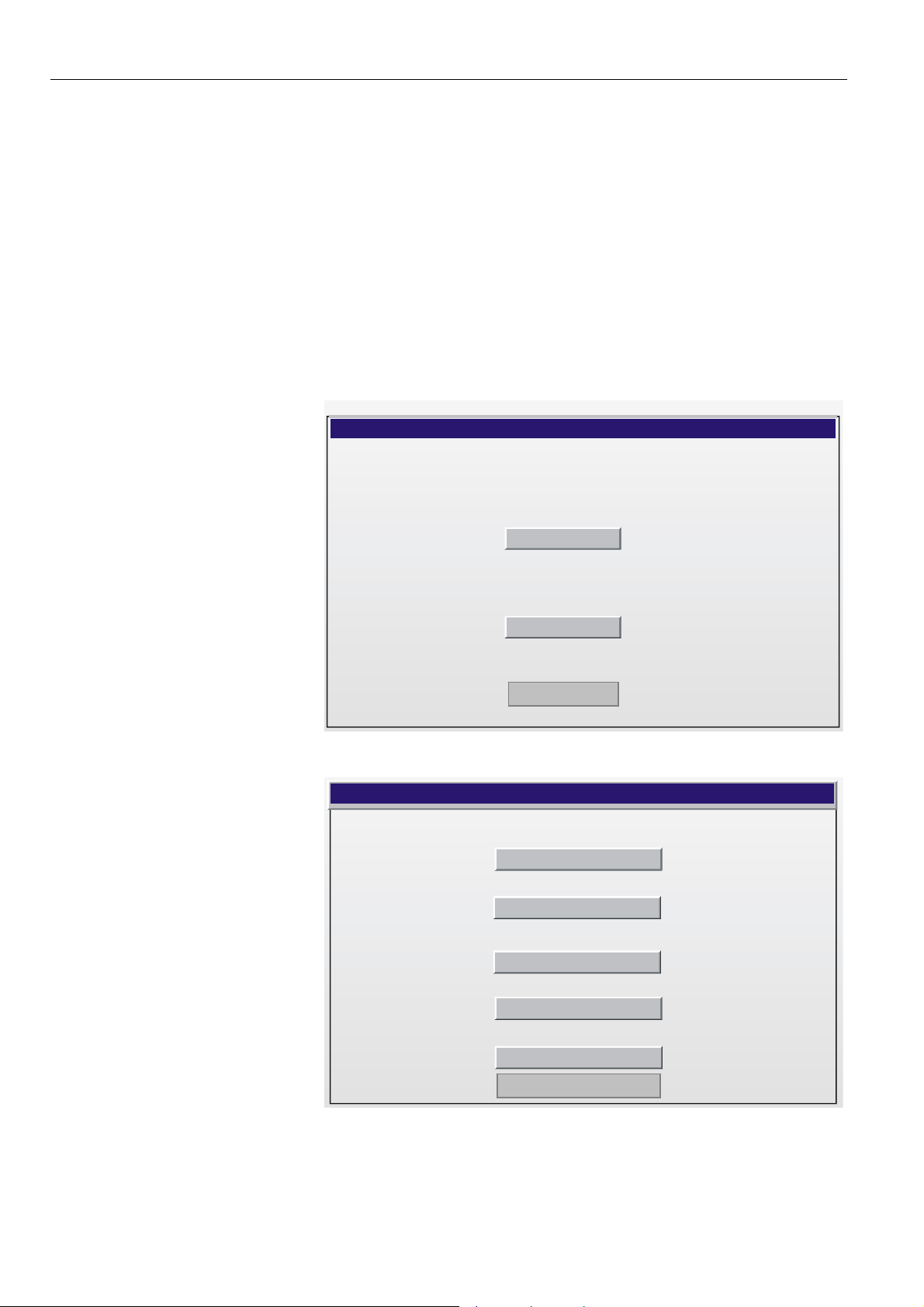
Case 2 On successful detection of an Excel Web controller by the XI882, the screen
below will be displayed. For further procedure, please refer to the “Configure XI882
for Excel Web Controller” section.
Excel Web
Set up
Continue
Fig. 6. Excel Web of operation startup screen
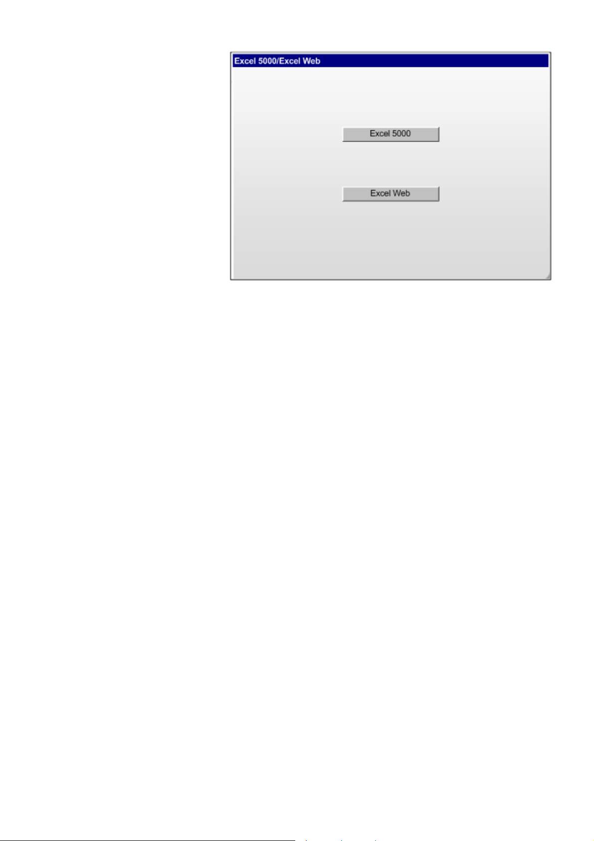
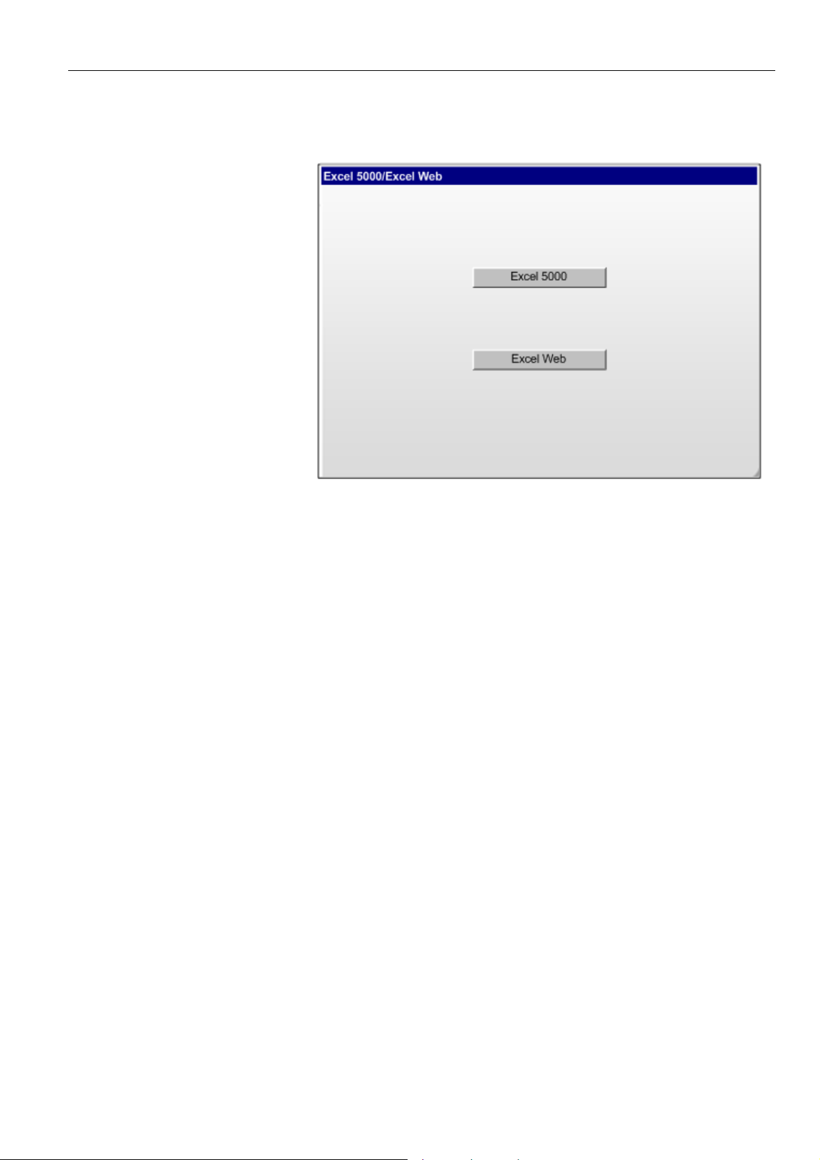
Case 3, 4 If XI882 detects both an Excel 500 family controller and an Excel Web controller, or
if XI882 does not detect any controller, the screen below is displayed. You can
select any mode of operation.
EN2B-0615GE51 R0709 14
Page 15
USER GUIDE XI882
Fig. 7. Startup screen when both controllers/ no controllers are available
For further detailed instructions on operating an Excel 500 family controller or Excel
Web controller, please refer to the following sections:
• “Operate Excel 500 Family Controller”
• “Configure XI882 for Excel Web Controller” and “Operate Excel Web Controller”
15 EN2B-0615GE51 R0709
Page 16
XI882 USER GUIDE
Configure XI882 for Excel Web Controller
Depending on the detection of the controller connected to the XI882, there are two
possible Excel Web scenarios:
Case A: The XI882 detects the Excel Web controller.
Case B: The XI882 does not detect the Excel Web controller.
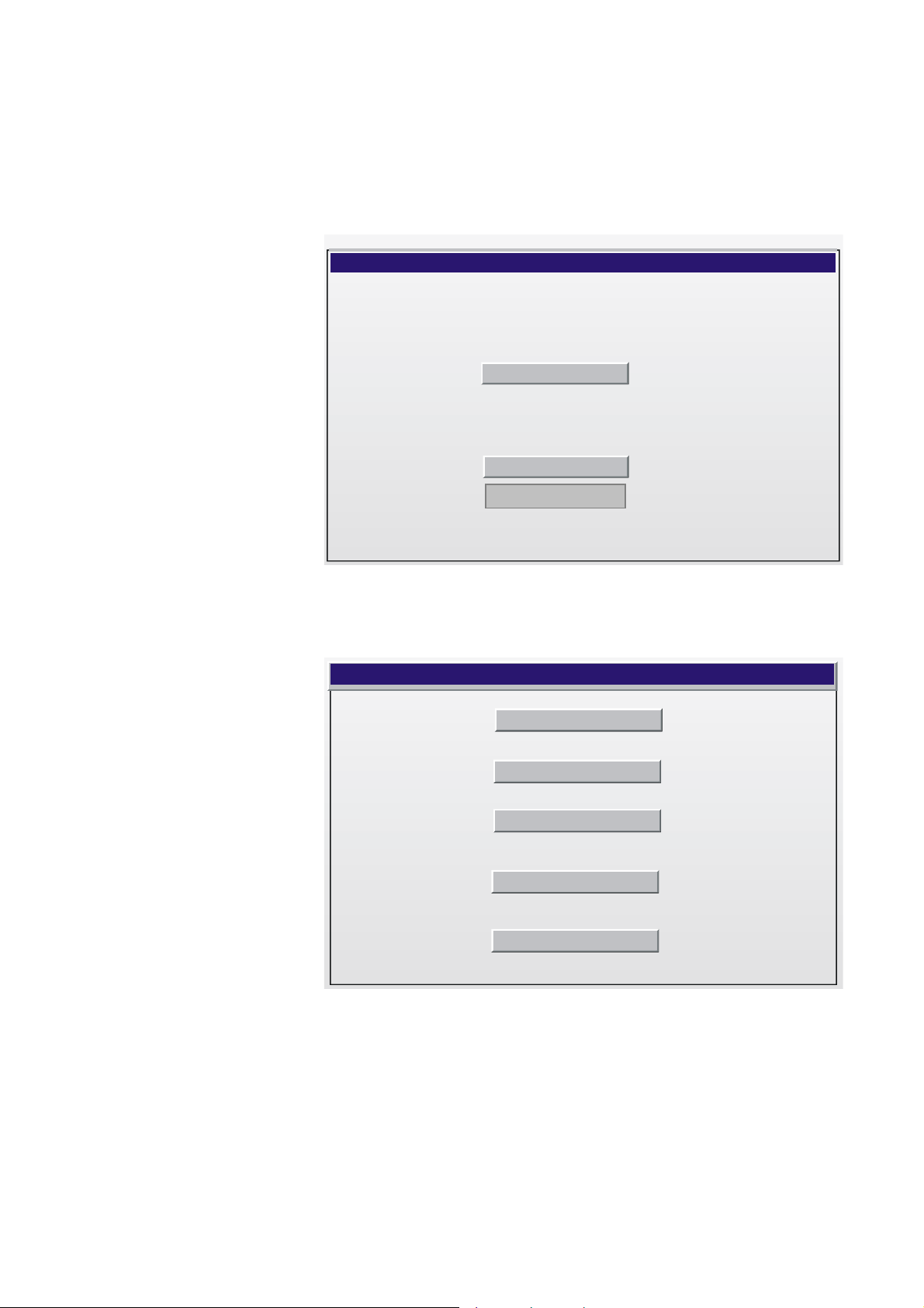
Case A (Excel Web is detected) Upon successful detection of an Excel Web controller by the XI882, the screen
below will be displayed. When tapping the Set up button, you will be able to do the
Interface-related settings as well as to set the Excel Web IP address. This screen
has a time-out of 20 sec, so if you do not select any of the options, the screen will be
automatically replaced after 20 sec by the Excel Web controller homepage.
If any network settings were done previously, these settings will be checked at the
time-out of this screen and the Excel Web homepage will be shown; otherwise, the
Interface settings screen stays on continuously.
You can also go to the Excel Web homepage by tapping the Continue button.
Excel Web
Set up
Continue
Fig. 8. Detection of an Excel Web controller
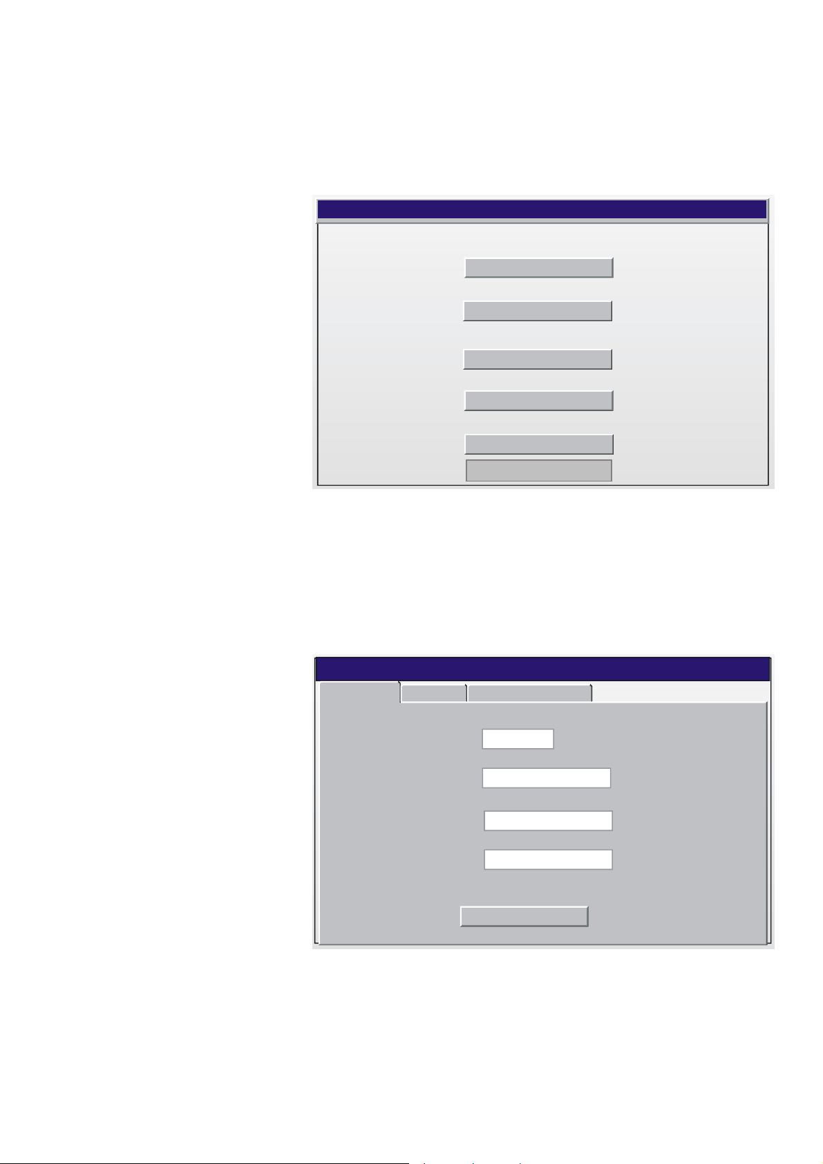
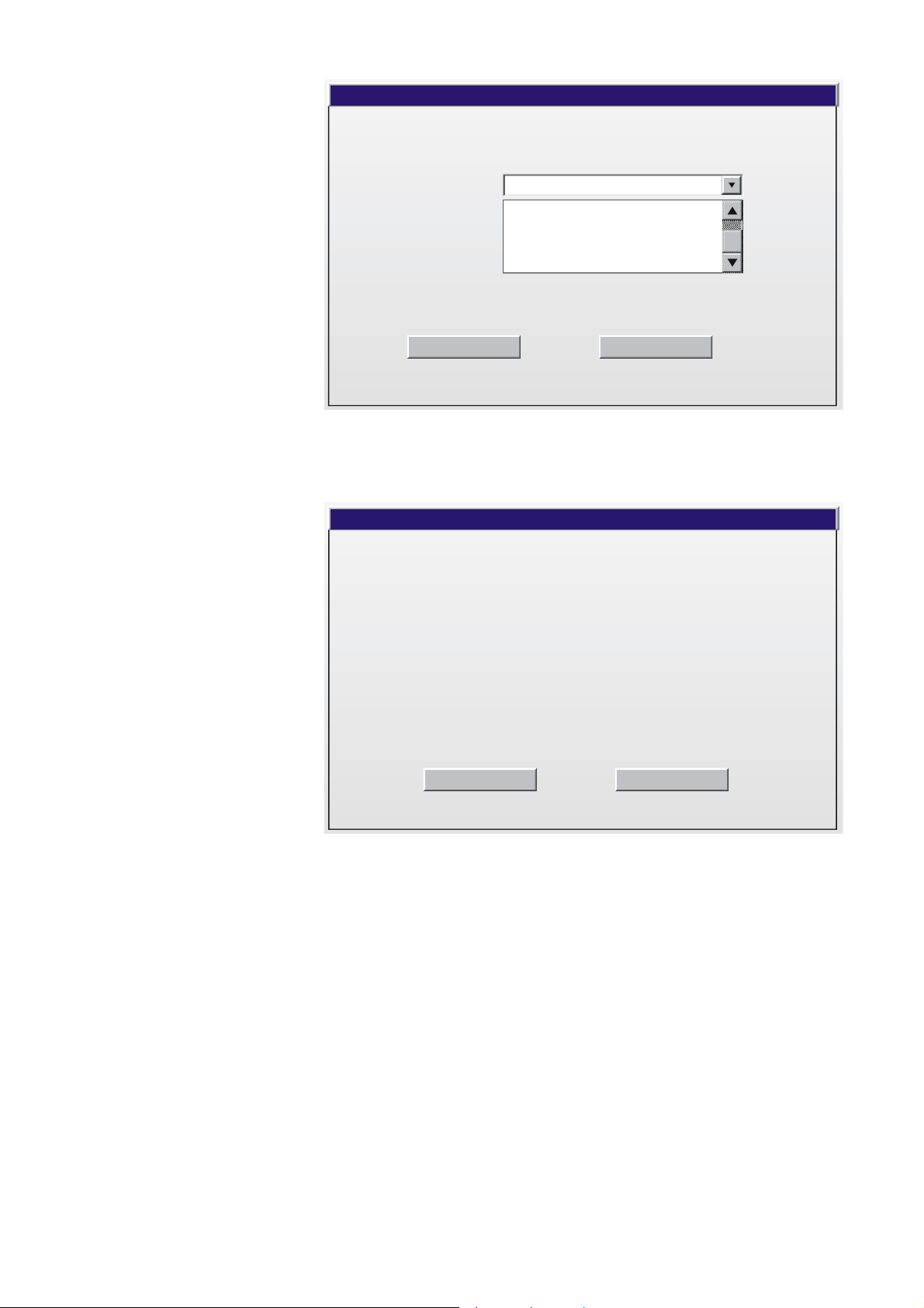
When tapping the Set up button, the following screen displays:
ExcelWeb.Setup
Network Settings
Calibrate
Backlight
Language
Continue
Network Settings Here you can input the IP settings for the XI882 and for the Excel Web controller.
EN2B-0615GE51 R0709 16
Page 17
USER GUIDE XI882
Calibrate Here you can calibrate the touch screen.
Backlight Here you can choose the backlight ON time.
Language Here you can select the language.
Continue Here you can go to the Excel Web homepage.
ExcelWeb.Setup
Network Settings
Calibrate
Backlight
Language
Continue
Fig. 9. Excel Web Set up
Network Settings The network settings window shows the following three tabs.
• IP Information
• IP Address
• Excel Web IP Address
IP Information tab
The IP Information tab displays the IP settings for the XI882 itself, with the
addresses for IP, Subnet mask and Default gateway. Address type can be DHCP or
Static as per selected IP address type on the IP Address tab.
ExcelWeb.NetworkSettings
IP Information
Address type :
IP Address :
Subnet mask :
Default Gateway :
IP Address Excel Web IP Address
DHCP
169.242.129.213
255.255.255.0
169.242.129.213
Close
Fig. 10. IP Information screen
17 EN2B-0615GE51 R0709
Page 18
XI882 USER GUIDE
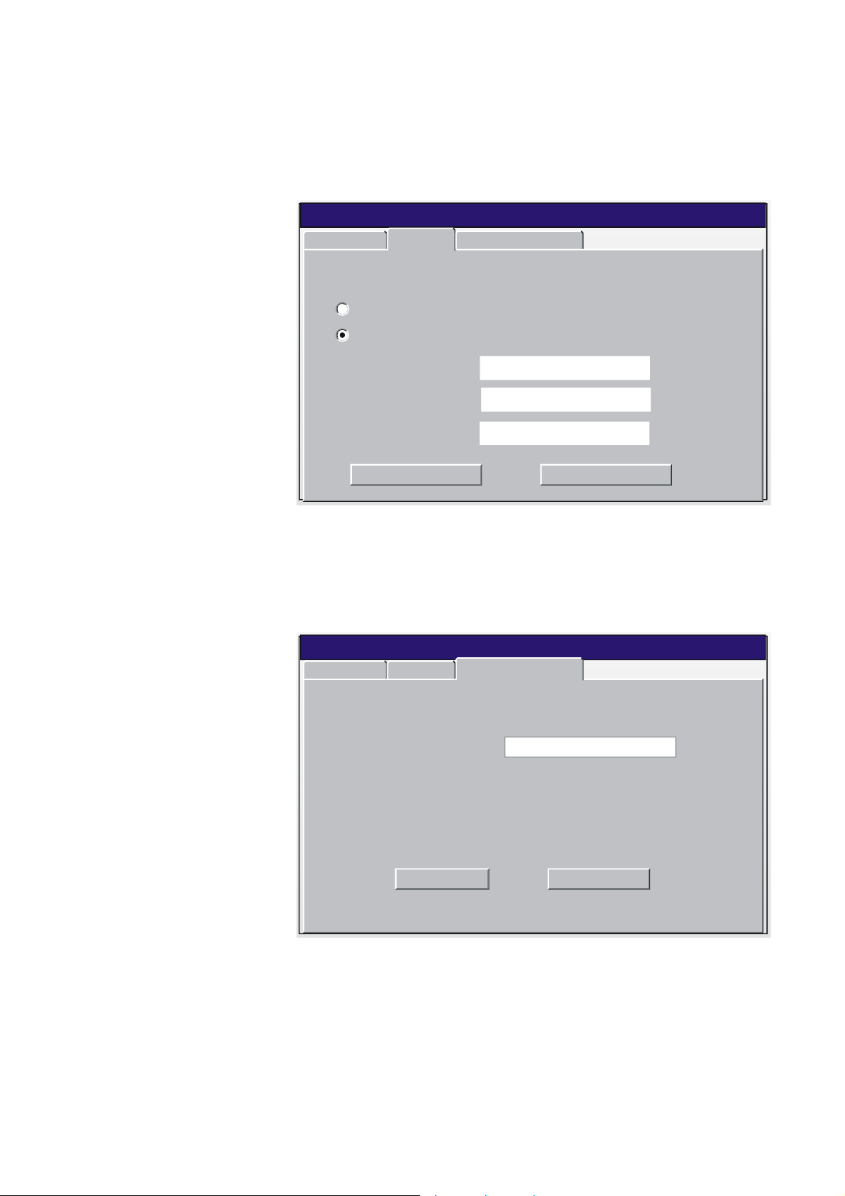
IP Address tab
The IP Address tab allows you to either manually specify an IP Address along with
the Subnet mask and default gateway addresses for the XI882 itself, or obtain these
addresses automatically via a DHCP server. Using a DHCP server will lower the risk
of IP address conflicts on the network.
Chose desired option and enter appropriate addresses. Tap Apply button to save
settings. Tap Close button if you want the settings left unchanged.
Excel Web . Network Settings
IP Information
An IP address can be automatically assigned to this computer
IP Address
Obtain an IP address via DHCP
Specify an IP address
Excel Web IP Address
IP Address :
Subnet mask :
Default Gateway :
Apply Close
169.242.129.213
255.255.255.255
.. .
Fig. 11. IP Address screen
Excel Web IP Address tab
Here you can specify the IP address of the Excel Web controller which you want to
access. Note that the IP address of the XI882 device and the Excel Web controller
must not be the same.
Tap Apply button to save settings, and then tap Close button.
Excel Web . Network Settings
IP Information IP Address
IP Address :
Excel Web IP Address
169.242.129.213
Apply Close
Fig. 12. Excel Web IP Address screen
Calibrate For calibration, you should place your finger or stylus on the crosshair shown on the
screen. This crosshair has five fixed positions on the screen which it follows one
after the other as you touch on the requested point on the screen. After this
sequence is complete, touch the display at any point to exit.
EN2B-0615GE51 R0709 18
Page 19
USER GUIDE XI882
Carefully press and briefly hold stylus on the centre of the target. Repeat as the target
moves around the screen. Press Esc key to cancel
Fig. 13. Calibration screen
NOTE: To cancel the calibration, tap on any point on the touch screen.
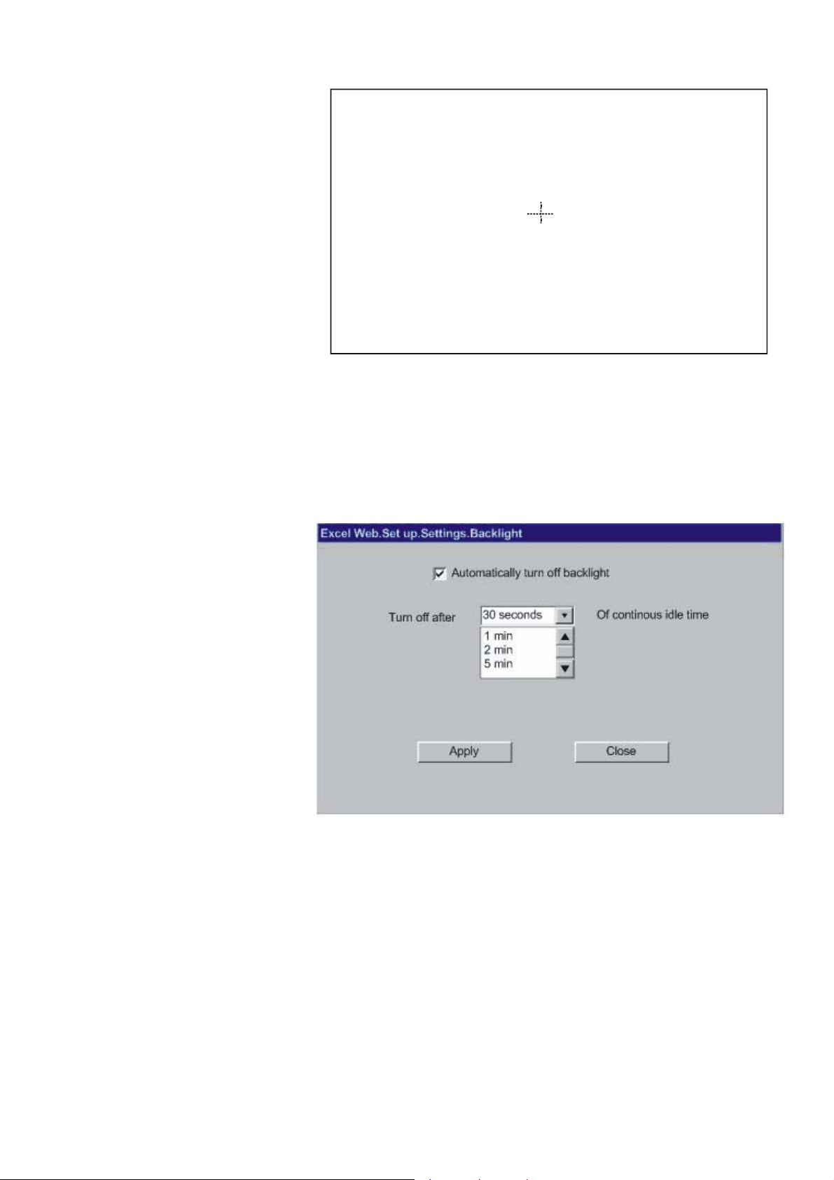
Backlight The Backlight option allows you to choose the duration for the backlight to remain
ON if the module is in the idle state. This option can be activated by checking
Automatically turn off backlight and then selecting the time from the drop-down
listbox below.
Tap Apply button to save settings, and then tap Close button.
Fig. 14. Excel Web backlight settings
Language The Language option allows you changing the language of the Excel Web set-up
screens. By default, the language is English. For the Excel Web set-up screens, the
XI882 supports English, French, Dutch, Spanish, Swedish, German and Japanese
languages.
NOTE:
By default, XI882 comes with English and German language pre-installed.
In order to make additional languages available, the screens have to be translated,
and an updated software, which includes the new language, has to be loaded into
the XI882.
In order to provide local language web-pages for the Excel Web operation, these
Excel Web web-pages have to be translated. For details, please refer to the Excel
Web Software Release Bulletin.
19 EN2B-0615GE51 R0709
Page 20
XI882 USER GUIDE
Excel Web. Set up.Language
Language :
Apply Close
English
German
French
Japanese
Fig. 15. Excel Web language set-up
Select the language from the Language drop-down listbox.
Tap Apply button to save setting. The change confirmation dialog box displays.
UI change request
In order for the UI changes to take effect the device must be reset
Ok Cancel
Fig. 16. Reset
Tap OK to restart XI882. Afterwards the screens will be displayed in the selected
language.
Continue When selecting Continue, the previous MMI settings are applied and the Excel Web
homepage is displayed on the screen.
EN2B-0615GE51 R0709 20
Page 21
USER GUIDE XI882
Fig. 17. Excel Web homepage
21 EN2B-0615GE51 R0709
Page 22
XI882 USER GUIDE
Case B (Excel Web is
not detected) If no Excel Web controller or an unconfigured Excel Web controller is connected, or
if the network settings of XI882 and Excel Web do not match, the Excel Web screen
is displayed.
The Continue button on this screen is disabled as there are no or non-matching
previous settings stored on the Excel Web controller connected to XI882. You must
setup the network settings for the controller from scratch in order to be able to view
the Web pages.
Excel Web
Set up
Continue
Fig. 18.
Tap Set up button. The Excel Web Set up screen displays. On this screen, the
Continue button remains disabled until the network settings are updated
successfully.
Excel Web. Set up
Network Settings
Calibrate
Backlight
Language
Continue
Fig. 19.
Please refer to the “Network Settings” section to enter/update the network settings.
Once the network settings are successfully updated, you can proceed to the Excel
Web homepage by tapping the enabled Continue button.
EN2B-0615GE51 R0709 22
Page 23
USER GUIDE XI882
Configure XI882 for Excel 500 Family Controllers
If XI882 detects both an Excel 500 family controller and an Excel Web controller, or
if XI882 does not detect any controller, the screen below is displayed. You can
select any mode of operation.
Fig. 20. Startup screen when both controllers/ no controllers are available
In order to operate an Excel 500 family controller, make sure,
– that the correct serial cable (XW585 or XW885) is connected both to
XI882 and to the controller
– that the controller is powered up, running and operational with a loaded
application.
– that in case a common transformer is used for XI882 and the
controller(s), 24VAC and zero (signal ground) are not mixed up!! If this is
the case, the serial cable will create a ground loop and a short circuit,
which will result in a powerless XI882 (black display).
23 EN2B-0615GE51 R0709
Page 24
XI882 USER GUIDE
OPERATE EXCEL 500 FAMILY CONTROLLER
If an Excel 500 series controller is detected, a homepage like the following displays.
Fig. 21. Excel 500 Family Controller Home Page
Horizontal Icon Bar Icon Name Function
Home Displays the Home page, which is the
Bus-wide
Switch Controller
Login / Logout: Allows logging in/logging out to/from a
Refresh Refreshes (updates) the actual screen
Configuration Allows setting/changing the
Trending Allows recording datapoints in graphical
Fast Access List overview.
Allows accessing any controller on the
bus
controller with specific access level
configuration of XI882 and the controller
(e.g. display, table sort order, date and
time, and others).
format, and storing onto USB memory
devices.
Operating Icons
Vertical Icon Bar
EN2B-0615GE51 R0709 24
System Alarms Allows viewing system alarms
Icon Name Function
Fast Access Lists Allows creating, changing and deleting
Time programs/
Schedules
fast access lists, i.e. a quick view of
datapoints, parameters, time programs
Allows viewing, creating, changing and
deleting schedules
Page 25
USER GUIDE XI882
Datapoints
Parameters Allows viewing, creating, changing and
Controller Allows uploading/downloading
Information Allows viewing information about the
Allows viewing, creating, changing and
deleting datapoints
deleting parameters
applications, downloading controller
firmware and FLASH EEPROM
operations
project, controllers, plants and control
loops
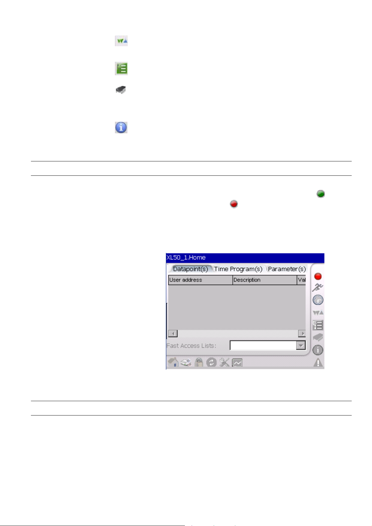
Online/Offline Controller Status Indication
At any point of time during any operation mentioned above, if the controller happens
to go offline i.e. through disconnection with XI882, the green LED icon
screen will turn into a red LED icon
and ‘Refresh’ icons will be disabled unless and until the controller is reconnected to
XI882. When XI882 is offline, tapping the Refresh icon will start the auto detect
function to reconnect to the controller. During this auto detection process, the LED
icon is blinking alternately in red and green color. Upon successful reconnection, the
previous screen will be re-enabled.
and all other icons except the ‘Configuration’
on the
Fig. 22. Controller is offline
NOTE: Tap the Refresh icon, after you have connected to a different controller!
Column Width Adjustment
The width of the columns displayed can be adjusted to match the length of the text
that is displayed, e.g. datapoint names, time programs, etc.
Simply tap with stylus or finger on the borderline between two columns, keep the
stylus or finger on the display and move to the left or right. As soon as you release
the stylus or finger from the display, the column width will change.
25 EN2B-0615GE51 R0709
Page 26
XI882 USER GUIDE
Sort Lines Option
The sequence of the lines can be sorted, by tapping on the header field of a column.
A small arrow in the right side of the column header will display whether
incrementing or decrementing sort order is active.
This option can be of interest when datapoints or other information is to be sorted,
like for incrementing sequence or for decrementing sequence.
Enter Data
Data such as values and names are done using the Input Panel which is
automatically invoked and available when necessary.
To enter data, tap the desired keys in the Input Panel.
To confirm entered data, tap on the Enter key in the Input Panel or tap on the
‘tick mark’ displayed in the dialog.
NOTE: Confirming data using the Enter key in the input panel is only applicable
to changes of:
- datapoint attributes
- datapoint values in time programs
- parameter values
- scaling of trend value graphs
EN2B-0615GE51 R0709 26
Page 27

USER GUIDE XI882
XI882 Connected To An Applicationless Controller
If the connected controller does not contain any application, then only the
following icons are enabled:
• Red Offline Indicator
• Controller
• Information
• System Alarms
• Refresh
• Login
• Bus-wide / Switch Controller
To provide the application, you have to login with access level 3 and then
download the appropriate application in the controller. At the same time you
may also connect to any controller on the C-Bus using the bus-wide
functionality to perform regular operation for that controller.
27 EN2B-0615GE51 R0709
Page 28
XI882 USER GUIDE
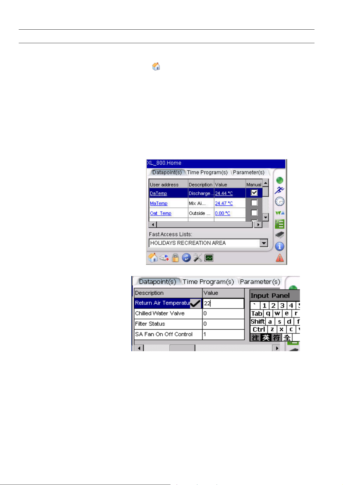
Home
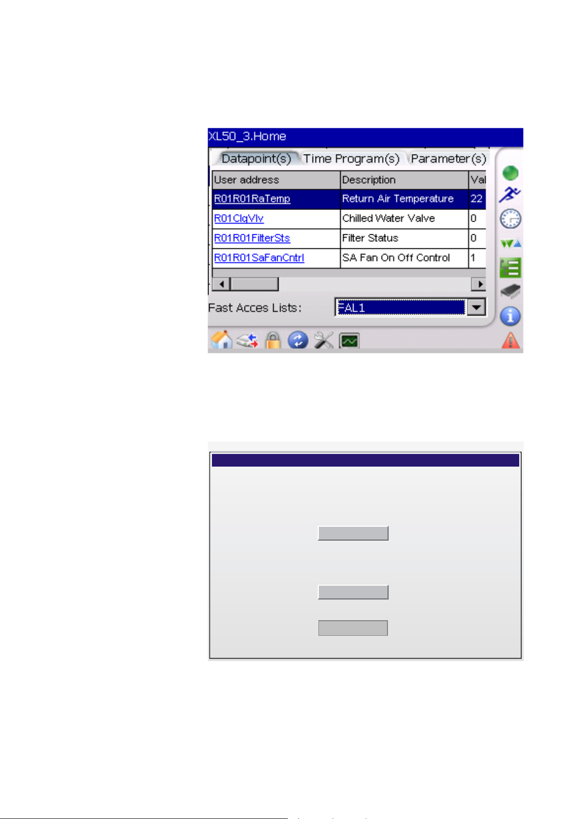
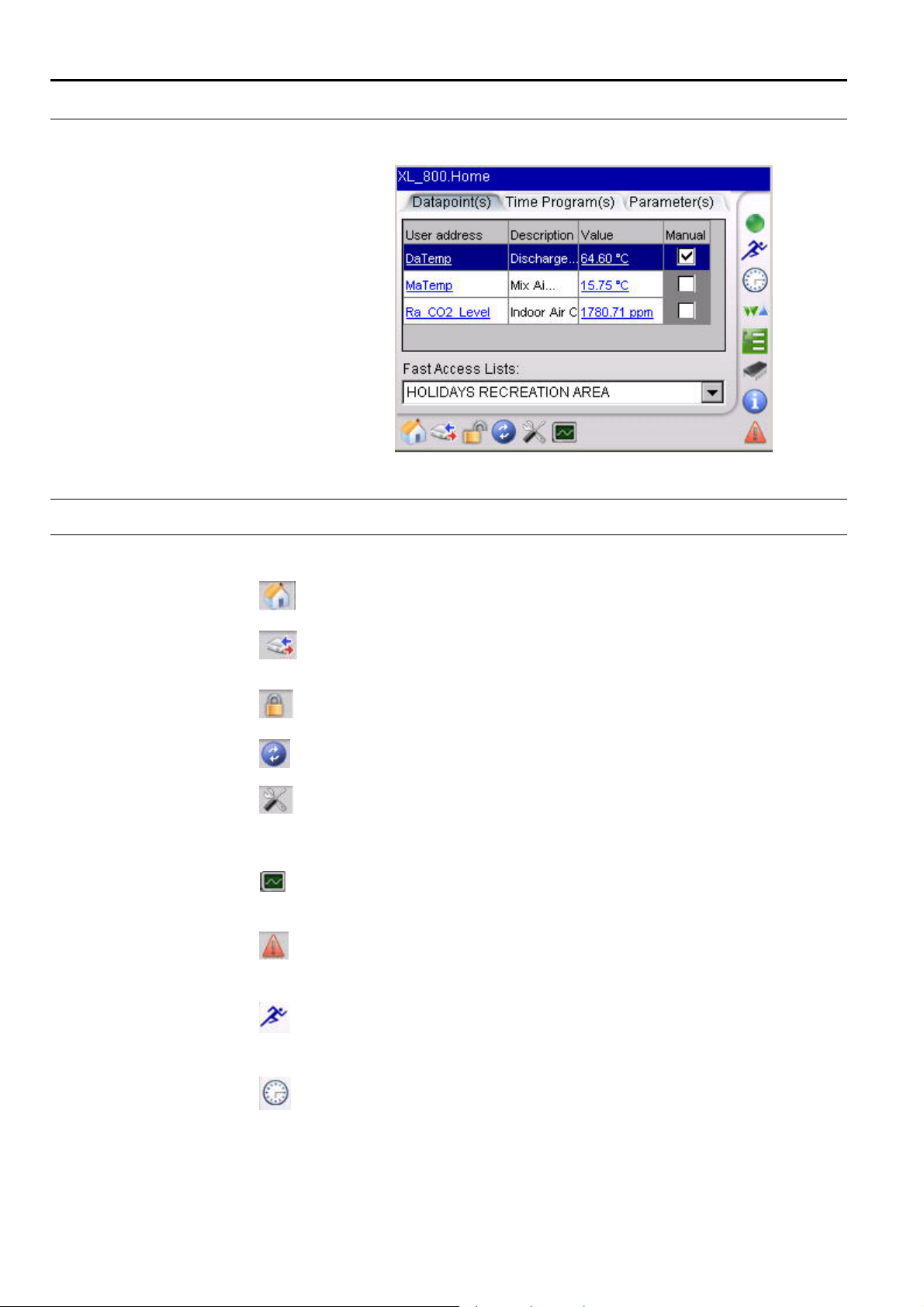
By default, the Excel 500 series homepage displays ‘Fast Access Lists’.
You will always be directed back to the homepage when selecting the
icon. A Fast Access List (FAL) is a user-defined collection of
selected
• Datapoints,
• Time Programs,
• and Parameters
which can be viewed quickly for frequent monitoring of these values.
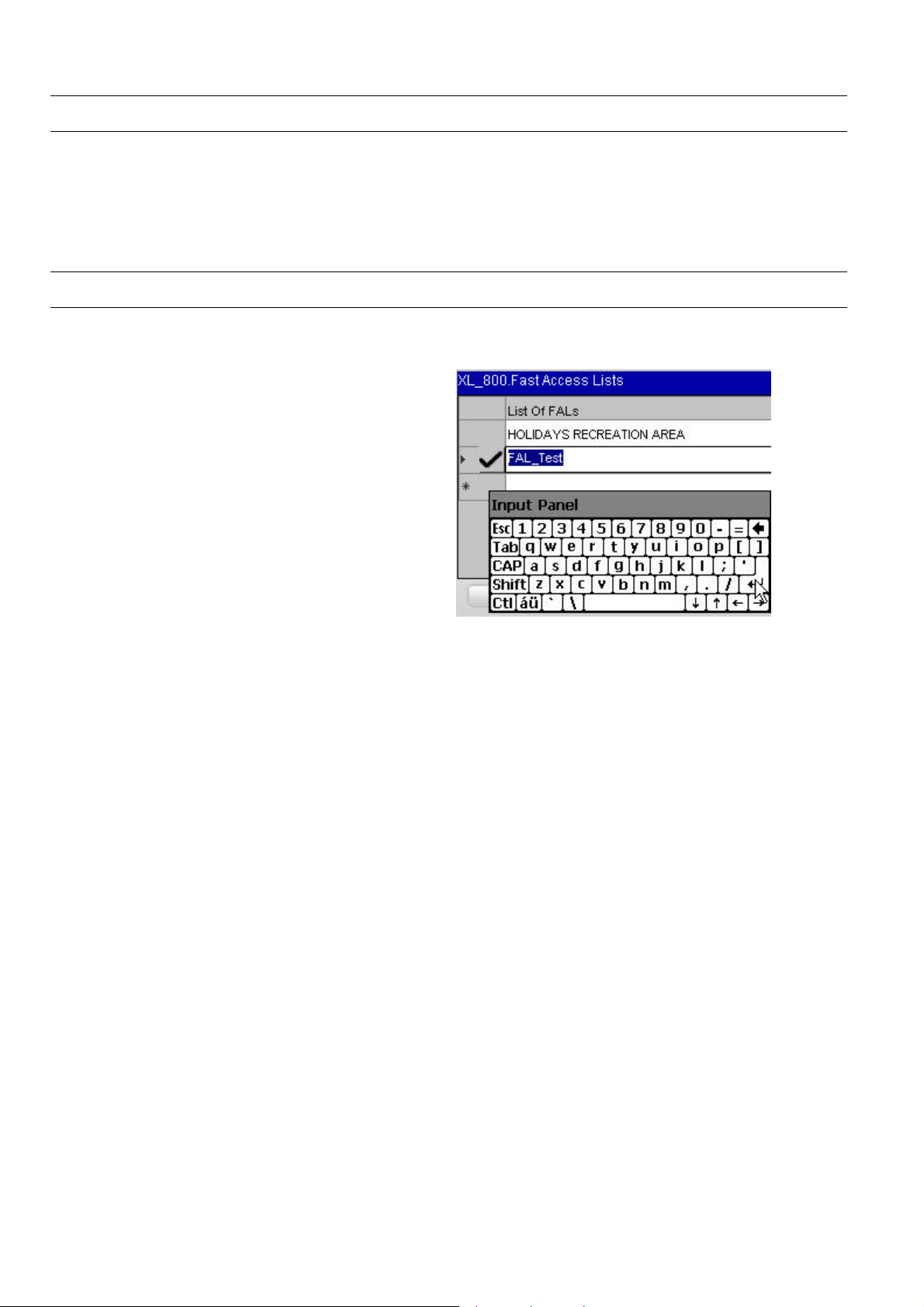
Initially there are no FALs available. You can create new FALs by tapping
the FAL icon. To create a new FAL, refer to the FAL section.
The desired FAL can be selected using the Fast Access Lists dropdown list box. You can change values by tapping on the Values column
of a datapoint and entering the desired value with the help of the input
panel. To save the changed value, tap on either the ‘tick mark’ in the
column or the Enter key in the Input Panel.
Fig. 23. Detection of an Excel 500 series controller
Fig. 24. Modifying/Changing values of datapoints
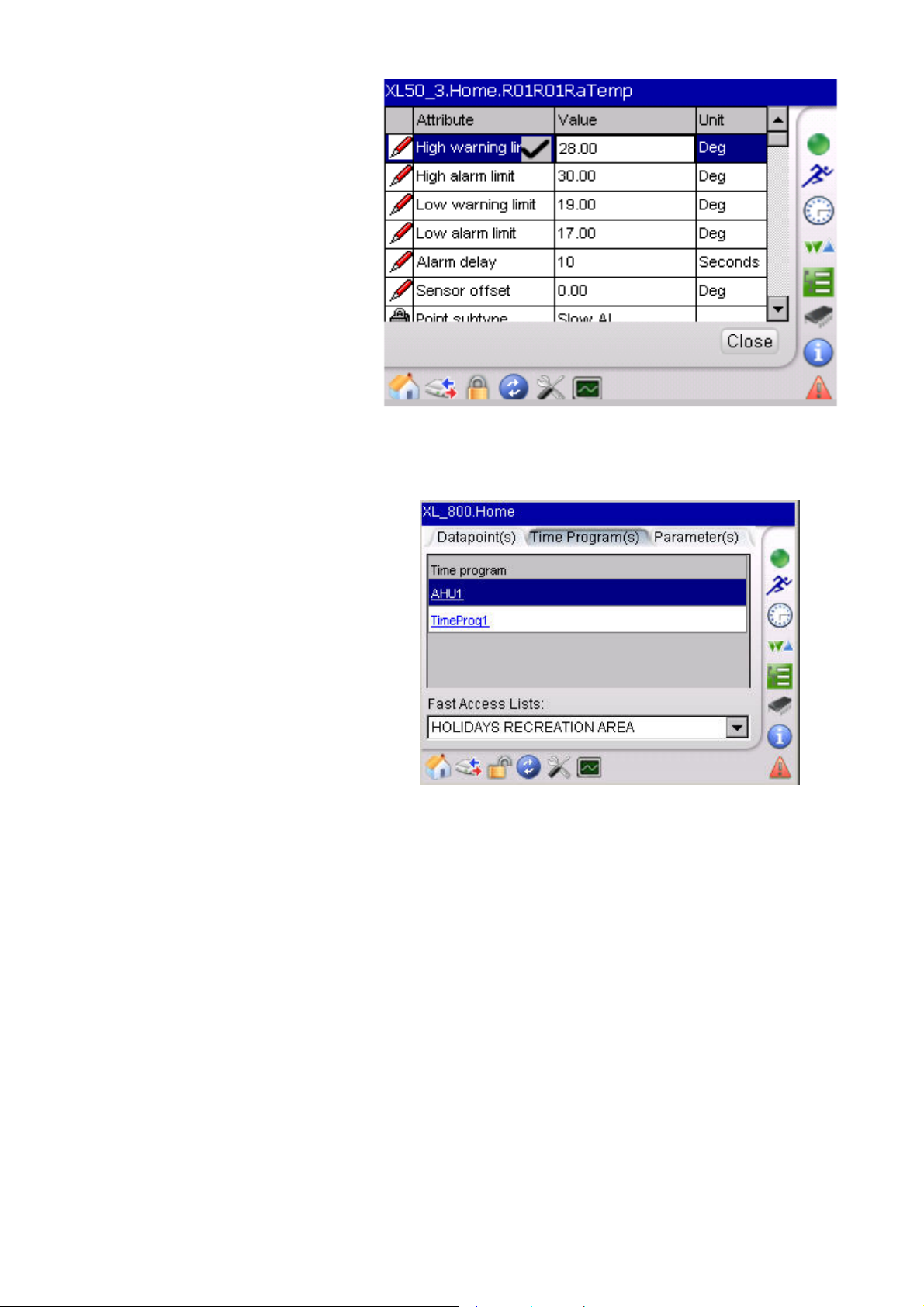
To get the attributes of a particular datapoint, you can select the desired
datapoint in the User Address column. This displays the attributes screen.
The attributes with ‘PEN’ symbol can be edited while the attributes with
‘LOCK’ symbol cannot be edited. Enter the new value with the help of the
input panel and tap ‘tick mark’ to save the value.
EN2B-0615GE51 R0709 28
Page 29
USER GUIDE XI882
Fig. 25. Datapoint Attributes
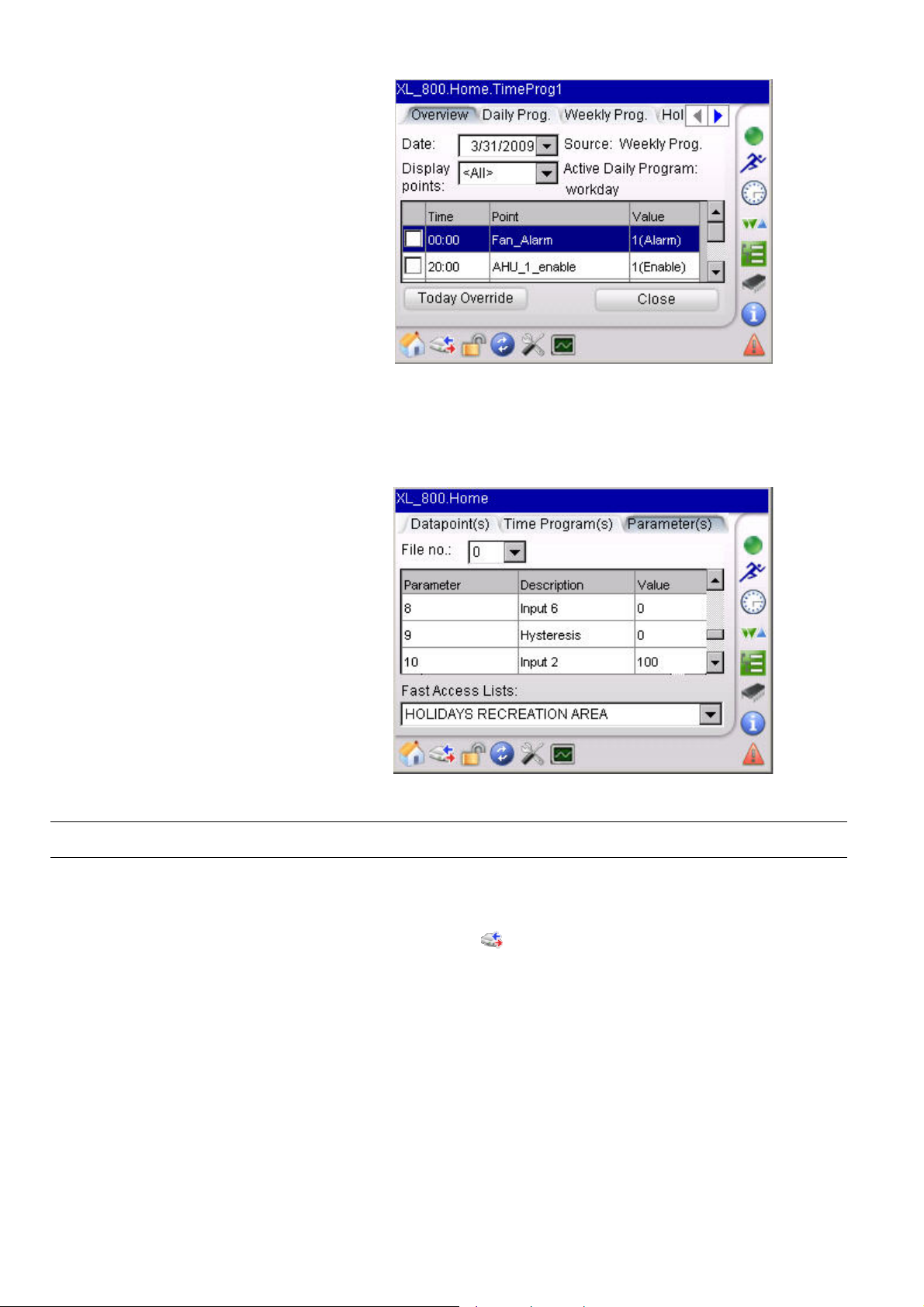
The Time Program(s) tab will direct you to the screen. The screen displays the
time programs assigned to previously selected FAL. You can select another FAL
from the Fast Access Lists drop-down list box.
Fig. 26. Display of Selected Fast Access List (Time Programs)
On tapping the title in the Time Program Name column, you will be
forwarded to the details of the particular time program. The details of the
time program are explained in the “Time Program” section. On selecting
the Close button you will be returned to the previous screen.
29 EN2B-0615GE51 R0709
Page 30
XI882 USER GUIDE
Fig. 27. Overview of Time Programs
The Parameter(s) tab will forward you to the screen displaying the
parameter number, its description and also its value. The parameters are
stored in files and these files can be selected by choosing the appropriate
file from the File no. drop-down list box. You can select another FAL from
the Fast Access Lists drop-down list box.
Fig. 28. Display of Selected Fast Access List (Parameters)
The Excel Touch MMI is capable of buswide access, i.e. the Excel Touch
can access any controller on the bus though it is physically connected
only to one controller on the C-bus. You can use buswide access by
tapping on the
from the Controller drop down listbox.
NOTE: On the LON bus, also front-ends like EBI or SymmetrE will appear in the
Controller drop down listbox. When selecting a front end like EBI or
SymmetrE, Excel Touch will attempt to verify the application version, will
fail to do so, and subsequently will fall back to the operation of the local
controller.
EN2B-0615GE51 R0709 30
Buswide Access
icon. You will then have to select the desired controller
Page 31

USER GUIDE XI882
Fig. 29 Buswide Access
On selecting OK, you will be forwarded to the homepage of that controller
as shown below.
Fig. 30. Buswide Controller Homepage
Login/Logout
A user can access any controller via XI882 by having one of three access levels. All
users have basic access to view the information about parameters, data points, time
programs etc. but in order to change/modify these values a user must have level 2
or level 3 access. Both access levels are password protected. You have to select
the
icon to gain access to these levels.
NOTE: You can login with one level only once at the same time.
The following table gives an overview of the various access levels required by the
different functionalities:
Functionality Level 1 Level 2 Level 3
Home/
Fast Access Lists
Bus-wide Access 9 9 9
8 8 9
31 EN2B-0615GE51 R0709
Page 32

XI882 USER GUIDE
Login/Logout 9 9 9
Configuration
Trending 9 9 9
Alarms 9 9 9
Information 9 9 9
Controller 8 8 9
Parameters 8 8 9
Datapoints 8 8 9
Time Programs 8 9 9
Fast Access List
Configuration
9= Full access
8 = Read Only access
Access Levels required for sections within the ´Configuration`
Functionality Level 1 Level 2 Level 3
Controller-Clock 8 9 9
Controller-RACL
Cycle Time
ControllerCommunication
HMI-Display 8 9 9
HMI-Calibrate 9 9 9
HMI-Backlight 8 9 9
HMI-Language 9 9 9
HMI-Clock 9 9 9
HMI-Options 8 8 9
9= Full access
8 = Read Only access
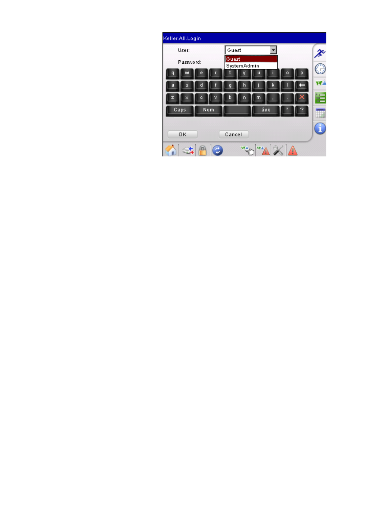
In the Login screen, tap the Login button.
Please see the table below for the access levels for different
sections within this functionality.
8 8 9
Functionality:-
8 8 9
8 8 9
EN2B-0615GE51 R0709 32
Fig. 31. Login screen
Page 33

USER GUIDE XI882
In the Enter Password screen, enter the right 4 digit password for your level. The
password can be in the range of 0000 to 9999.
Fig. 32. Password Login screen
Tap Ok button. You are directed to the homepage of the controller and the Lock
symbol indicates ‘Unlocked’ status.
If the entered password is incorrect, the message ‘Incorrect Password!!!’ pops up
Selecting Close directs you back to the Login Screen.
Fig. 33. Error message for incorrect password
You can change the password for an access level. The change password option is
only enabled if you have access level 3.
NOTE: It is necessary to use different passwords for level 2 and level 3. Using
the same password for level 2 and level 3 results in having access only
for level 2.
33 EN2B-0615GE51 R0709
Page 34

XI882 USER GUIDE
Fig. 34. Change Password option enabled
The screens for access levels 2 and 3 are shown below.
Fig. 35. Level 2 password change screen
EN2B-0615GE51 R0709 34
Page 35

USER GUIDE XI882
Fig. 36. Level 2 password changed successfully
Fig. 37. Level 3 password change screen
Fig. 38. Level 3 password changed successfully
35 EN2B-0615GE51 R0709
Page 36

XI882 USER GUIDE
If you do not enter the same password in the Confirm field, an error pops up and
you will have to enter the password again. An error is also generated if you try to
apply blank passwords.
Fig. 39. Password change error
Fig. 40. Password change error
EN2B-0615GE51 R0709 36
Page 37

USER GUIDE XI882
Configuration
The configuration for the XI882 as well as the controller can be accessed by
icon. On selecting this icon the following screen appears.
Fig. 41. Configuration Screen
Tapping the Controller button, forwards you to the screen where you can view or
change the settings related to the controller. Viewing/changing settings depends on
the user´s access level.
Fig. 42. Controller Configuration Screen
Tapping the Clock button allows changing the clock settings of the controller
37 EN2B-0615GE51 R0709
Page 38

XI882 USER GUIDE
Fig. 43. Controller Clock Configuration
In the Date and Time fields, enter data and time. The controller can also be
instructed to use the clock of the XI882 MMI by tapping the Use HMI Clock
checkbox.
Tapping the Apply button will apply the changes. Tapping Close will return you
back to the previous screen.
Fig. 44. Daylight Savings Time Controller Configuration
Daylight savings is used in some countries and hence there is a provision to set the
controller clock according to these conditions. The Daylight Savings Time tab is
primarily used for this purpose.
You have to specify the range of days for which you want to enable the daylight
savings using the From and To fields. The Enable DST checkbox has to be tapped
in order to enable daylight savings during the selected period of days. You can also
decide whether the DST should be enabled from Sunday or any other Fixed Day.
Tap Apply button, and then tap Close button.
EN2B-0615GE51 R0709 38
Page 39

USER GUIDE XI882
All applications running in the controller are based on RACL software. Each RACL
cycle has its own cycle time. The RACL screen is for display only and shows the
current cycle time. The range of cycle time is 0.25 secs to 60 secs.
The Communication screen allows viewing the communication settings of the bus
and/or the modem. On the bus, the XI882 communicates with the controller via the
controller´s assigned controller number. The Controller No. field displays the
number of the currently connected controller.
NOTE: When disconnecting XI882 from the controller, it must be power cycled
before re-connecting it to the controller.
C-Bus number will be displayed correctly.
Fig. 45. RACL Cycle Time Screen
Only this will ensure that the
39 EN2B-0615GE51 R0709
Page 40

XI882 USER GUIDE
Fig. 46. Bus Configuration
On the Modem tab, you can disable the modem by tapping Disable Modem
checkbox at startup (controller should be x reset prior to this operation).
The modem options are only enabled if there is no application loaded/running in the
controller, otherwise they are disabled.
If you want to use the modem you must reset the controller manually and then
configure the modem as described in the following. Set the Baud Rate, the GSM
PIN required to dial a number from the controller over the GSM network, and the
Application Memory in the range of 38 to 128 which will be allocated to the current
application.
The Trend entries are automatically calculated by the controller dependent on the
specified application memory. You cannot modify/change the number of trend
entries.
The Reset Modem button will reset the modem configuration to default settings.
Tap Apply button for saving of settings made.
Tapping the HMI button in the Configuration screen allows access to the following
functions shown in Fig. below...
EN2B-0615GE51 R0709 40
Fig. 47. Modem Configuration
Page 41

USER GUIDE XI882
Fig. 48. HMI Configuration
Refresh The refresh settings allow defining the refresh rate for displayed values. Tap on
Update Interval drop-down list box and select an update interval. Tap Apply button.
Fig. 49. XI882 Display Settings
Calibrate XI882 screen can be calibrated using this function. Tapping Calibrate displays the
screen below. Follow the predetermined sequence of points on the screen where
the crosshair appears in order to calibrate the touch screen.
NOTE: Once finished with the calibration touch the screen once at any place in
order to leave the calibration screen.
41 EN2B-0615GE51 R0709
Page 42

XI882 USER GUIDE
Carefully press and briefly hold stylus on the centre of the target.
Repeat as the target moves around the screen. Press Esc key to
cancel
Fig. 50. XI882 Calibration Settings
Backlight This function defines the ON time for the backlight off XI882 is in the idle state. Tap
checkbox Automatically turn-off backlight after and select the time from the Turn
off after drop-down list box. Tap Apply button.
Fig. 51. XI882 Backlight Settings
EN2B-0615GE51 R0709 42
Page 43

USER GUIDE XI882
Fig. 52. XI882 Backlight Settings
NOTE: The backlight timeout settings will survive a WIN CE update and power
fail, but will be lost after a software update. After a software update of
XI882, the backlight timeout settings must be set again.
Language The following languages can be selected online:
• English
• Dutch
• German
• French
• Spanish
• Swedish
• Japanese
NOTE: Before an additional language other than those listed above is available,
the operation pages have to be translated into that language, and the
XI882 software has to be updated accordingly.
Tap on the Selected Language tab, and then select the language from the
Language drop-down list box. Tap the Apply button, and then tap the Ok button in
the message box.
Fig. 53. XI882 Language Settings
NOTES: The selected language will survive powerfail and Windows a CE update.
After a Windows CE update, the language setting will be reset to the
English language. To avoid loosing the selected language, it can be
43 EN2B-0615GE51 R0709
Page 44

XI882 USER GUIDE
backed up before the Windows CE update and restored after the
If the XI882 needs to be replaced with a new XI882, back up the
To back up the language setting to the USB stick, select the Backup/Restore tab,
and then tap the Backup button.
Windows CE update.
language setting of the old XI882 to the USB stick, and then restore the
language setting from the USB stick to the new XI882.
Fig. 54. Backup Language
Expand the tree and select the Languages folder.
Tap checkmark to save the file to the Languages folder.
To restore the language setting from the USB stick, tap the Restore button.
EN2B-0615GE51 R0709 44
Page 45

USER GUIDE XI882
Fig. 55. Restore Language
Expand the tree and select the Languages folder where the backed up file is stored.
Tap checkmark to restore the file from the Languages folder.
Clock This function allows changing the date and time setting of the XI882 MMI. The Date
tab allows you to set the current date. Tap the Date drop-down list box and select
the date. Tap Apply button t o set the new date
Fig. 56. XI882 Date Settings
The Time and Time Zone tab allows changing the current time of XI882 and
selecting the time zone for the geographical location in reference to GMT in which
XI882 is used. After setting the time and time zone, tap Apply button.
Fig. 57. XI882 Time Settings
Options The options screen allows modifying/changing settings for B-port, controller
upload/download, Firmware delay and general settings of the XI882.
45 EN2B-0615GE51 R0709
Page 46

XI882 USER GUIDE
Fig. 58. XI882 Port Settings
On the Ports tab, you can override the communication baud rate between XI882 and
the controller by tapping the checkbox Switch to 38400 baud on connect. All
communication between XI882 and the controller will communicate at this baud rate,
if not checked then XI882 and the controller communicate at the baud rate set for
the controller. Tap Apply button after doing any changes.
On the Controller tab, you can enable/disable the following settings:
• Stop Controller during upload/download
If checked, the controller is stopped during uploading or downloading an
application
• Display LON interface change warning
If checked, a warning is displayed when the LON interface has been changed.
• Set Controller number automatically
If checked, it is set according to the current conditions
• Set bus baud rate automatically
If checked, the default value is the factory setting
• Set Bus ID automatically
If checked, it is set according to the current conditions.
On the Firmware tab the intersection can be set for downloading the firmware file
which is downloaded in sections into the controller. The firmware download has a
fixed Intersection Delay. Enter the value in the Intersection Delay field.
EN2B-0615GE51 R0709 46
Fig. 59. XI882 Controller Settings
Page 47

USER GUIDE XI882
Fig. 60. XI882 Firmware Settings
Tap Apply button.
On the General tab, tap the Show all digits of Datapoint Values checkbox if you
want to see all digits of datapoint values.
Tap Apply button.
Fig. 61. XI882 General Settings
47 EN2B-0615GE51 R0709
Page 48

XI882 USER GUIDE
Trending
The icon allows trending of datapoints (collection of historical datapoint
value/status information).
Prerequisites
In order to use the trending function, the following prerequisites are needed:
1) USB memory device, like USB memory stick
2) The directory “TrendFiles” must have been created on the USB memory device.
3) At least 300 Mbytes free space on the memory device, i.e. for recorded trend
data continuously over 24 hrs. If the memory device becomes full during
recording the data will not be recorded from that point and you will loose
subsequent data.
Behavior when USB memory is disconnected during trending
When the USB memory device is detached while trending is active, trending will
stop. Once a USB memory device is connected again, the desired datapoints have
to be put into trend again.
Maximum number of points to be trended
At any time, a maximum of 20 points can be selected for a controller,
and a maximum of 8 datapoints can be displayed simultaneously on the Trend
Graph at the same time.
Trending after Power Fail and Windows CE update.
The trend settings of the active trend for the physically connected controller before
the powerfail or Windows CE update will survive the WIN CE update and power fail.
In these scenarios, trending will automatically continue afterwards with the same
settings as before (selected datapoints, scales and colors). In case the controller
application has been changed, the trending will not automatically restart.
After a software update of XI882, the trend settings will be lost if they are not backed
up before and restored after the software update.
• This is valid for the latest trend that had been active (when the XI882 had been
connected to a local controller or to a bus-wide controller.
• For these cases, the trending has to be restarted manually.
The Trending screen displays five options on the initial New/Open tab. You can:
• create a new trending file
• open an already existing trend file
• close a existing open trend file.
• back up a trending file
The trending files have an .htf extension and are stored in the TrendFiles folder
on the memory device.
• restore a trending file
EN2B-0615GE51 R0709 48
Page 49

USER GUIDE XI882
Fig. 62. XI882 General Settings
New/Open New Trend File
Allows creating a trend file on the memory device on which the selected datapoint’s
data will be stored during recording. Initially this button is enabled and it gets
disabled after opening a trend file. After tapping this button you are directed to enter
a name for the file that is to be created on the memory device. You can then type in
the name. Tapping on the ‘tick mark’ will open the file and tapping on the ‘Cross
Mark’ will cancel the operation. On successful creation, the newly created trend file
is opened by default.
Fig. 63. Creating a new trend file
Open Trend File
Allows opening any existing/newly created trend file present on the memory device.
Initially this button is enabled and its get disabled after successful opening a trend
file. If no file is open, then all the buttons on the Options tab are disabled. On
tapping this button, a dialog box displays to select trend file from TrendFiles folder
on the memory device.
49 EN2B-0615GE51 R0709
Page 50

XI882 USER GUIDE
Fig. 64. Opening an existing Trend File
Close Trend File
Allows closing an existing opened trend file. Only available after the trending has
been stopped.
Fig. 65. Closing an open Trend File
To back up a trend file to the USB stick, tap Backup button.
Expand the tree and tap TrendSettings folder. Tap checkmark to save the file to the
TrendSettings folder.
EN2B-0615GE51 R0709 50
Fig. 66. Backup Trend
Page 51

USER GUIDE XI882
Tap OK in the message box to confirm the backup.
NOTES: After a software and/or Windows CE update, the trend file is backed up
automatically on the hard disc.
If the XI882 needs to be replaced with a new XI882, back up the trend file
to the USB stick of the old XI882, and then restore the trend file from the
USB stick to the new XI882.
To restore a trend file from the USB stick, tap Restore button.
Fig. 67. Restore Trend
Expand the tree and select the TrendSettings folder where the backed up file is
stored. Tap checkmark to restore the file from the TrendSettings folder.
NOTES: After a software and/or Windows CE update, the trend file is restored
automatically from the hard disc.
If the XI882 needs to be replaced with a new XI882, back up the trend file
to the USB stick of the old XI882, and then restore the trend file from the
USB stick to the new XI882.
Options Start/Stop Recording
Starts the recording of datapoint values or stops the recording of values of all
selected datapoints
51 EN2B-0615GE51 R0709
Page 52

XI882 USER GUIDE
Fig. 68. Start Recording
Fig. 69. Stop Recording
On tapping this button, recording will start or stop in background.
Select Datapoints
Allows selecting the datapoints that are to be recorded in trending. On selecting this
button you are directed to the datapoint selection screen where you can select the
desired datapoint by checking the checkbox for that particular datapoint and also
changing its polling interval in the Polling Cycle time column. The polling time
range varies from 1 second to 1 hour. You can also sort the datapoints according to
name using the Filter field. After selecting the desired datapoint(s), tap Start button.
The selected datapoints are saved and the Graph tab is set to recording mode. To
display particular datapoints of the selected datapoints, go to the Line Info tab and
select datapoints as described in the “Line Info” section.
Fig. 70. Selecting Datapoints for trending
NOTE: You have to go to the Line Info tab to select the datapoints to be
displayed on the graph.
EN2B-0615GE51 R0709 52
Page 53

USER GUIDE XI882
History
Shows the history of the recordings for the open trend file. The Recording in File tab
shows the list of the recordings saved in that file since the trend file´s creation date.
The data is represented in two columns, First Value to Last Value. Tapping the Ok
button forwards you to the Graph tab.
Fig. 71. Trending History
Similarly, the Datapoints in record tab shows the list of datapoints that have been
added to the trend file since the trend file´s creation date. The datapoints can belong
to different controllers.
Data Export
Allows exporting the trend file in .csv format to the memory device. The Recording
tab shows the list of recordings similar to the history screen. You can export a
specific recording from this list by selecting the desired row and then tapping on the
Export button, or export all the information by tapping the Export All checkbox and
then tapping the Export button. You can also selecting the duration of the export
data by choosing the appropriate date and times in the From and To combo boxes.
Fig. 72. Data Export
53 EN2B-0615GE51 R0709
Page 54

XI882 USER GUIDE
NOTE: Depending on the number of trend records it can take several minutes
until the Data Export screen is displayed after the Data Export button
has been pressed. Below are two examples.
No. of trend records *.htf Filesize Time to display Data Export screen
22547 784 KB 2,5 Minutes
115 724 2,15 MB 6,5 Minutes
Similarly you can also export all the datapoints for the opened trend file using the
Datapoints tab.
Fig. 73. Data Export
On the Separator tab, you can select the separator (delimiter) to be used in the
.CSV file.
Fig. 74. Data Export
All the exported information will be stored on the memory device in the TrendFiles
folder. If this folder is not present on the device, you must create it.
On tapping the Export button you are asked for the name of the file to be created so
that the trend data will be stored in CSV file format in the TrendFiles folder on the
memory device. Enter the name of the file using input panel.
On successful exporting the trending data from the controller to the specified
location on the memory device, a message box displays which indicates the amount
of data in terms of line values that has been written to the newly created file.
EN2B-0615GE51 R0709 54
Fig. 75. Creating a file for Data Export
Page 55

USER GUIDE XI882
Tap on the Close button to close the message box.
Fig. 76. Creating a file for Data Export
Graph
The Graph tab allows viewing the graphical presentation of the trended datapoint
values selected on the Line Info tab (see description below) for the recorded
duration. Initially when no trend file is opened, the screen displays ‘No Data’ in light
green color on the background of the screen. During recording, the background text
changes to ‘Recording’ and if the recording is stopped, then the background text is
displayed as ‘Stopped’.
You can display the vertical axis by tapping on any of the trend lines and then scroll
down the axis according to your needs. In the same way, you can adjust the
horizontal axis by just holding the stylus on any position on the X-axis and just
dragging it according to your needs.
Fig. 77. Graph displays
Fig. 78. Graph displays
To view the current value at a definite time, tap on the line to mark it, and then tap
on the desired point of time. The value and the date are shown in a tooltip.
55 EN2B-0615GE51 R0709
Page 56

XI882 USER GUIDE
When trend recording occurs over midnight, the date of the next day is shown on the
X-axis.
If you want to view a particular datapoint, then go to the Line Info tab and tap the
desired datapoint, and then switch back to the Graph tab to view that particular
trend.
Line Info
Shows the selected datapoints (checked) that will be displayed on the Graph tab
along with the value of the point, and the minimum and maximum scale values.
You can vary the scale values by just tapping on them and entering the new values
using the input panel.
Fig. 79. Value displays of trend graph
EN2B-0615GE51 R0709 56
Fig. 61. Line Information
Page 57

USER GUIDE XI882
Alarms
Alarms can be checked by selecting the icon. Here you can view details of
active alarms, alarm history, as well as bus-wide alarms.
Alarms cannot be acknowledged via the XI882 user interface, but only via a frontend, like EBI, SymmetrE etc.
Fig. 80. Alarms
Tapping the Points in Alarm button shows active alarms i.e. alarms that are
currently active/on. Each alarm is displayed by Date, Time and Datapoint name.
From the Alarm Type drop-down list box, you can tap alarms per severity
(critical/non-critical) and system alarms.
Fig. 81. Points in Alarm
To view more details about an alarm, tap the alarm in the list, and then tap Details
button. The details show the alarm severity, controller that has generated the alarm,
etc.
57 EN2B-0615GE51 R0709
Page 58

XI882 USER GUIDE
Fig. 82 Alarm Details
You can view all the alarms that have been generated in the past using the
Controller Alarm History button. The XI882 requires some time to access the
history and hence displays the message ‘Loading Alarm History’ while retrieving
history details. Tapping Close button in the message box allows you to proceed to
another screen if you do not want to wait while software retrieves the complete
history from the controller. The message box will automatically disappear after the
history loading is completed.
At most the last 99 alarms can be retrieved from the controller.
In the Alarms History screen each alarm is displayed by Date, Time and Datapoint
name. From the Alarm Type drop-down list box, you can tap alarms per severity
(critical/non-critical) and system alarms. To view more details about an alarm, tap
the alarm in the list, and then tap Details button. The details show the alarm
severity, controller that has generated the alarm, etc.
EN2B-0615GE51 R0709 58
Fig. 83. Alarm History
Page 59

USER GUIDE XI882
Fig. 84. Alarms History
Fig. 85. Alarm Details
Bus-wide alarms can be viewed by selecting the Bus-wide Alarms button from the
Alarms screen. Bus-wide alarms are alarms generated from controller(s) that are not
physically connected to the XI882 but reside on the same network and are logically
connected to it over the network.
Fig. 86. Bus-wide Alarms
In the Bus-wide Alarms screen, tap on the controller on the list of the alarms you
want to see. Then tap Details button. In the following screen each alarm is
59 EN2B-0615GE51 R0709
Page 60

XI882 USER GUIDE
displayed by Date, Time and Datapoint name. From the Alarm Type drop-down list
box, you can tap alarms per severity (critical/non-critical) and system alarms.
Fig. 87. Bus-wide Alarms List
To view more details about an alarm, tap the alarm in the list, and then tap Details
button. The details show the alarm severity, controller that has generated the alarm,
etc.
Fig. 88. Bus-wide Alarms Details
EN2B-0615GE51 R0709 60
Page 61

USER GUIDE XI882
Information
Controller information can be viewed by tapping the icon. Information can be
viewed in detail by tapping one of the following buttons:
• Details
• Application Status
• Application Parts
Fig. 89. Controller Information screen
Information is only displayed and cannot be edited.
Details When tapping Details button, detailed information about the controller such as
Country code, Controller name, Program name, Controller number, Current version
of the firmware loaded on the controller, etc. is shown.
Fig. 90. Controller Information Details
Application Status When tapping Application Status button, details of the application currently running
in the controller is shown. The Value (status) of the application and application parts
is either running or stopped.
61 EN2B-0615GE51 R0709
Page 62

XI882 USER GUIDE
Fig. 91. Controller information Application Status
Application Parts When tapping the Application Parts button, the screen shows the values (Value
column) in number of RAM Bytes of all currently running application parts
(Description column).
Fig. 92. Controller Information Application Parts
EN2B-0615GE51 R0709 62
Page 63

USER GUIDE XI882
Controller
You can download/upload applications, download firmware to the controller and load
programs in the FLASH EEPROM tapping the Controller button
The corresponding Controller screen provides the following functions:
• Application
• Firmware Download
• Flash EEPROM
.
Fig. 93. Controller options
Application Tapping the Application button allows starting the actual application in the
controller or stopping the application already running in the controller.
Fig. 94. Controller Application START/STOP
To start the application, tap the Start button, to stop the application tap the Stop
button.
63 EN2B-0615GE51 R0709
Page 64

XI882 USER GUIDE
Upload tab
Applications can be uploaded from the controller using this tab.
NOTE: Alarm polling stops during application upload/download.
Prerequisite
1) A USB memory device must be inserted into the touch-panel.
2) On that USB memory device the directory “ApplicationUploadFiles” must be
present (to be created with Laptop or PC beforehand).
Fig. 95. Application Upload Screen
Initially the Upload button is disabled as no destination folder is selected. Tap the
Select button and choose the destination folder.
Fig. 96. Target folder selection Screen
The folder ApplicationUploadFiles needs to be created on the USB memory device if
it is not present, otherwise an already existing folder is shown. Tapping the ‘tick
mark’ will select the folder and allow you to upload the files by tapping the Upload
button.
EN2B-0615GE51 R0709 64
Page 65

USER GUIDE XI882
Fig. 97. ‘Upload’ enabled after selecting destination folder
Download tab.
Applications can be downloaded from the XI882 MMI using this tab.
NOTE: Alarm polling stops during application upload/download.
Prerequisite
1) A USB memory device must be plugged into the touch-panel.
2) On that USB memory device the directory “ApplicationDnloadFiles” must be
present (to be created with Laptop or PC beforehand).
Fig. 98. Application Download Screen
Tap the Select button and select the desired “.pra” file from the location on the
XI882. Then tap Download button to download the file to the Excel 500 series
controller. The Download button is initially disabled as the target file is not selected.
If the destination folder ApplicationDnloadFiles is not present on the USB memory
device, an error pops up. Tap Close button in the message box and create the
specific folder on the USB memory device.
65 EN2B-0615GE51 R0709
Page 66

XI882 USER GUIDE
Fig. 99. Error message for destination folder
If the folder already exists on the drive, the screen shown below is displayed.
Tapping ‘tick mark’ selects the .pra file in the folder and enables the Download
button. The ‘wrong mark’ will cancel the operation.
Fig. 100. Selection of Destination folder for download
Fig. 101. ‘Download’ enabled after selecting destination
EN2B-0615GE51 R0709 66
folder
Page 67

USER GUIDE XI882
At any time during upload/download you can tap Cancel button to abort the
upload/download. Tap Yes button in case you have start canceling the process and
really want to abort the upload/download.
Fig. 102. Cancel request confirmation
Firmware Download You can view firmware details by tapping the Firmware Download button in the
Controller screen.
Firmware tab
This tab gives information about the currently loaded firmware.
Fig. 103. Firmware Details
Tap Close button after viewing the firmware information.
Download tab
Prerequisite
1) A USB memory device must be plugged into the touch-panel.
2) On that USB memory device the directory “FirmwareDnloadFiles” must be
present (to be created with Laptop or PC beforehand).
Here you can download the firmware into the controller. Tap Select button and
choose the appropriate firmware file for downloading to the controller. If the
destination folder FirmwareDnloadFile is not present on the USB memory device, an
67 EN2B-0615GE51 R0709
Page 68

XI882 USER GUIDE
error pops up. Tap Close button in the message box and create this specific folder
on the destination disk.
Fig. 104. Selecting file for Firmware Download
Tap the Download button to start the download.
After you have selected the firmware, the following screen shows the file path, the
action currently being executed while downloading, the version of the firmware being
downloaded and the overall status of the process.
Fig. 105. Firmware Download
FLASH EEPROM Tapping the FLASH EEPROM button in the Controller screen provides the following
functions:
• Save the application to the FLASH EEPROM
• Erase the application from the FLASH EEPROM
• Load the application from the FLASH EEPROM
EN2B-0615GE51 R0709 68
Page 69

USER GUIDE XI882
Fig. 106. Controller FLASH EEPROM options
When tapping the Save Application button, the current application is saved to the
FLASH EEPROM. The following message is displayed after completion. Tap Close
button in the message box.
Fig. 107. Saving Application to the FLASH EEPROM
When tapping the Erase Application button, all the applications on the FLASH
EEPROM are erased. The following message is displayed after completion. Tap
Close button in the message box.
Fig. 108. Erasing Application from the FLASH EEPROM
69 EN2B-0615GE51 R0709
Page 70

XI882 USER GUIDE
When tapping the Load Application button, you can load an application from the
FLASH EEPROM. The fixed applications available on the FLASH EEPROM are
displayed. Tap the application you want to load in the list, and then tap Load button.
Fig. 109. Loading Application from the FLASH EEPROM
After successful loading of the application, a message window pops up indicating
that the application has been loaded. Tap Close button in the message box.
Fig. 110. Loading Application Complete
EN2B-0615GE51 R0709 70
Page 71

USER GUIDE XI882
Datapoints
NOTE: After a power restoration, datapoints will be reloaded. Reloading is indicated with
the message ´Loading datapoints…`.
The
When the datapoints icon is tapped for the first time, XI882 requires some time to
load all datapoints, and while doing so displays the message ‘Loading Datapoints’.
The message will automatically disappear after the datapoint loading is finished.
icon displays the datapoint information on the screen.
Fig. 111. Loading Datapoints
Fig. 112. Datapoint screen
The column width can be adjusted by dragging the column separation line right or
left.
Sorting of lines can be done by tapping on the column header. Tapping the Manual
column header sorts the lines according to the Manual status of the datapoints. The
small arrow at the right side of a column indicates ascending or descending sort
order.
71 EN2B-0615GE51 R0709
Page 72

XI882 USER GUIDE
Fig. 113. Sorting Datapoints
The Filter field can be used to sort and view specific datapoints which you wish to
view/change. For example, entering ‘S’, all the points starting with ´s` will be
displayed in the list. To filter for certain datapoint names, enter the desired string
and then tap Show button.
Fig. 114. Filtered Datapoints
In addition to the filtering of datapoint names, the Point type drop-down list box
allows filtering particular datapoint types according to the following table:
• AI – Analog Input
• AO – Analog Output
• DI – Digital Input
• DO – Digital Output
• AR – Analog Remote
• AV – Analog Value
• DR – Digital Remote
• DV – Digital Value
• CI – Counter Input
• CV – Counter Value
• FP– Flexible Point
Tap the Point type drop-down list box and select the datapoint type in the list.
EN2B-0615GE51 R0709 72
Page 73

USER GUIDE XI882
Fig. 115. Filtered Datapoint Type ´DO`
A datapoint can then be selected and its details (attributes) can be viewed/changed
by tapping the name in the User address column.
Fig. 116. Datapoint attributes
Attributes having a ‘PEN’ icon in the Attributes column can be modified while
attributes having a ‘LOCK’ icon cannot be modified. To change a value, tap the
value column, select the new value, and then tap the ‘tick mark’ in the Attribute
column.
NOTE: The sensor offset cannot be changed.
73 EN2B-0615GE51 R0709
Page 74

XI882 USER GUIDE
Fig. 117. Datapoint attributes
You can also set an automatic datapoint value in hand. Tap in the Value column of
a datapoint. In the Value dialog box, select the Manual radio button, enter the new
value with the help of input panel, and then tap the OK button.
Value Display at Disconnection When the XI882 will be disconnected during operation, in the Value column
asterisks are displayed instead of the actual values.
Fig. 118. Forcing manual values on Datapoints
Parameters
In order to display parameter texts, they have to be imported into the XI882 from an
USB memory device.
Parameter texts can be imported for every controller on the bus. In order to import
parameter texts for a bus-wide controller (not the locally connected one), you have
to select the bus-wide controller, log into it, and then import the parameter texts for
it.
XI882 can not import the same parameter.txt file into more than one controlller.
Identical parameter.txt file names must be renamed on the USB stick before
importing them into XI882.
Parameter text files for the local controller and for the bus-wide controller must be
backed up before a software update and restored after the software update to avoid
a data loss.
NOTE: The Parameter Text Files for the physically connected controller and for
all bus-wide controllers will survive a WIN CE update and power fail.
EN2B-0615GE51 R0709 74
Page 75

USER GUIDE XI882
The icon displays parameters of the connected controller. For each parameter
the following properties are displayed:
• plant the parameter belongs to
• sub module of that plant
• control loop used in the sub module
• position
• others
Fig. 119. Parameters
Prerequisites
1) An USB memory device must be plugged into the touch-panel.
2) On that USB memory device, the directory “ParameterFiles” must be present (to
be created beforehand).
On the CARE PC, browse to the project folder and copy the parameter files (.txt) of
each controller to the directory “ParameterFiles” on the USB memory device. If
desired edit/translate the parameter files using a text editor.
Tap Import Information button.
Select the appropriate .TXT file from the list and tap the ‘tick mark’. Tap the ‘cross
mark’ to cancel the operation.
Fig. 120. Import Information
After selecting the file, the parameters will be loaded as the following screen shows.
75 EN2B-0615GE51 R0709
Page 76

XI882 USER GUIDE
Fig. 121. Imported Parameters
To view the details of parameters of a parameter file, select the parameter file in the
Parameters screen, and then tap the Parameters button. The screen displays all
the parameters contained in the file with their number, description, values and the
reference.
Fig. 122. Read Parameters
To back up a parameter text file to the USB stick, tap Backup button.
EN2B-0615GE51 R0709 76
Fig. 123. Backup Parameters
Page 77

USER GUIDE XI882
Expand the tree and select the ParameterTextFiles folder.
Tap checkmark to save the file to the ParameterTextFiles folder.
NOTE: If the XI882 needs to be replaced with a new XI882, back up the
parameter text file to the USB stick of the old XI882, and then restore
the parameter text file from the USB stick to the new XI882.
To restore a parameter text file from the USB stick, tap Restore button.
Fig. 124. Restore Parameters
Expand the tree and select the ParameterTextFiles folder where the backed up file
is stored.
Tap checkmark to restore the file from the ParameterTextFiles folder.
NOTE: If the XI882 needs to be replaced with a new XI882, back up the
parameter text file to the USB stick of the old XI882, and then restore
the parameter text file from the USB stick to the new XI882.
77 EN2B-0615GE51 R0709
Page 78

XI882 USER GUIDE
Time Programs
NOTE: After a power restoration, time programs will be reloaded. Reloading is indicated
with the message ´Loading time programs…`.
The
controller.
icon allows accessing all time programs available in the connected
Fig. 125. Time Program
To access a time program tap on the title of the time program in the list.
Fig 126. Time program Overview
Overview tab
This tab shows switchpoints of the time program valid on a day selectable in the
Date drop-down list box. By tapping and selecting from the Display points drop-
down list box, you can view all the points or filter them according to their type such
as AI, AO, DI, DO, etc. The screen also shows the source of the time program and
the used active daily program. For each switchpoint its Time, Point name and Value
is shown in the table.
To override a switchpoint, check the corresponding checkbox in the first column of
the switchpoint, and then tap the Today Override button. The Today Overrides
screen is displayed.
EN2B-0615GE51 R0709 78
Page 79

USER GUIDE XI882
Fig. 127. Time program Today’s Overrides
In the From Time and To Time columns, enter the dates defining the period of time
for overriding the values of the time program. In the Value column, enter the
override values.
Fig. 128. Time program Today’s Overrides
Tap the checkbox of the switchpoint in the first column. The switchpoint will only be
overridden if the switchpoint is checked. Tap the Save & Close button.
Daily Prog. tab
This tab shows the daily programs that are in use. You can create new daily
programs, delete daily programs, and delete switchpoints of a daily program.
79 EN2B-0615GE51 R0709
Page 80

XI882 USER GUIDE
Fig. 129. Daily Time Program
Tap on the Daily Prog. drop-down list box and select the daily program of the
switchpoints you want to view or delete.
Tap on the Display Points drop-down list box and select the point type (AI, AO, DI,
DO, etc.) you want to display.
To create a new switchpoint, tap on the point field of the empty line at the bottom
and select the desired point. Then, enter the desired time, value and optimization.
To delete switchpoints, tap the checkbox of the switchpoint you want to delete in the
first column
Tap the Delete Switchpoint(s) button.
To create a new daily time program, tap the New button.
In the New Daily Program screen, enter the name in the Daily program name field.
Tap the Copy Time Program From drop-down list box and select an already
existing time program that should provide the switchpoints for the new time program.
Tap the Save & Close button.
To the delete a daily time program, tap the Daily Prog. tab
Tap on the Daily Prog. drop-down list box and the select the daily program you
want delete.
EN2B-0615GE51 R0709 80
Fig. 130 New Daily Time program
Page 81

USER GUIDE XI882
Tap the Delete button
NOTE: Before deleting a daily program, make sure that the daily program to be
deleted is not referenced by any other time program. If it is referenced,
To complete the deletion of a daily time program, tap Yes button in the following
message box.
you are not allowed to delete the daily time program.
Fig. 131. Deleting Daily Time program
Weekly Prog. tab
This tab shows the time programs assigned to the days of the week. If you wish to
change the time program for a particular day of the week, tap the Daily Program
column for that day and choose the desired program from the drop-down list
displayed. To save the changes, tap the ‘tick mark’.
Fig. 132. Weekly Time program
Holiday Prog tab
This tab allows you to enable or disable the time programs scheduled for holidays in
the year. The Holiday Prog. column shows the description, the Daily Program
column shows the active time program for that day and the Date column shows the
date of the holiday.
To change a daily program for a holiday, tap the holiday program, tap in the Daily
Program column and select the desired daily program.
You must enable/disable a holiday program to override/not to override an existing
time program on a particular day by tapping the Enable or Disable radio button for
the selected holiday time program.
81 EN2B-0615GE51 R0709
Page 82

XI882 USER GUIDE
Fig. 133. Holiday Time Program
Fig. 134. Holiday Time Program
Yearly Prog. tab
This tab shows the time programs assigned for the weeks of the year. You can view
the time period of maximum 12 weeks. Here you can also override the time program
of a particular weekday by applying another time program.
EN2B-0615GE51 R0709 82
Fig. 135. Yearly Time Program
Page 83

USER GUIDE XI882
To define the time period, tap the Starting on drop-down list box and select the
starting date of the week in the calendar.
Tap the Shop … Weeks(s) drop-down list box and select the number of weeks the
time period should have.
Fig. 136. Yearly Time Program
To override the time programs for particular days in a week, tap the checkbox of the
date in the first column. Tap the Override with drop-down list box and select the
daily time program which should be used for overriding the daily program displayed
in the Daily Program column.
Tap Go button.
You can also override the active daily time program of a particular date by tapping
the corresponding Daily Program column and selecting the daily program that
should be used for the override.
Tap the ‘tick mark’ to save changes.
Fig. 137.Overriding daily programs in Yearly Time Program
83 EN2B-0615GE51 R0709
Page 84

XI882 USER GUIDE
Fig. 138. Overriding daily programs in Yearly Time Program
Fast Access List Configuration
The icon displays the Fast Access List (FAL) configuration view. A Fast Access
List is a list of datapoints, time programs and parameters that you view and change
most frequently. By default, the fast access list overview is the homepage of any
Excel 500 family controller. Initially, no FAL is available and must be created.
To create a new FAL, you need to login with password level 3.
Then tap the blank row and enter the name with the help of the input panel, then tap
the ‘tick mark’ to save the new FAL.
EN2B-0615GE51 R0709 84
Fig. 139. Fast Access List
Page 85

USER GUIDE XI882
Fig. 140. Creating a Fast Access List
To remove a FAL, select the desired FAL by choosing the ► symbol in first column
of the row, and then tap the Delete button. The row that contains a ‘
new row and can never be deleted.
To modify a FAL, tap the FAL in the list, and then select Edit button.
The individual FAL screen is displayed.
Fig. 141. Add/Remove Datapoints to/from FAL
Datapoints tab
Here you can add datapoints to the FAL by tapping the corresponding checkboxes
in the first column. Unchecking a datapoint removes the datapoint from the FAL.
A FAL displays the user address and the description of a datapoint.
Tapping the Save button, saves the current selected datapoints and shows them in
the FAL after tapping the Close button.
Time Program(s) tab
On this tab, you can add/remove time programs from/to a FAL.
*‘ symbol is the
85 EN2B-0615GE51 R0709
Page 86

XI882 USER GUIDE
Fig. 142. Add/Remove Time Programs to/from Fast Access List
On the Time Program(s) tab, check the checkbox in the first column of the time
program you want to add to the FAL. Uncheck the checkbox in the first column of
the time program you want to remove from the FAL.
Tapping the Save button, saves the current selected time programs and shows
them in the FAL after tapping the Close button.
Parameters tab
On this tab, you can add/remove parameters from/to a FAL.
You will first have to import the parameter file from the disk by tapping the Import
info button (please refer to the previous “Parameters” section for detailed
instructions). Then tap on the File No. drop-down list box and select the appropriate
file number.
Check the checkbox in the first column of the parameter you want to add to the FAL.
Uncheck the checkbox in the first column of the parameter you want to remove from
the FAL.
Fig. 143. Add/Remove Parameters to/from FAL
To import parameter descriptions, tap on Import Info button, browse to the
ParameterFiles folder, and then select the parameter file. Tap Check mark.
EN2B-0615GE51 R0709 86
Fig. 144. Select Parameter File
Page 87

USER GUIDE XI882
The parameter descriptions are imported and displayed in the Description column.
Fig. 145. Import Parameter Information
Tapping the Save button, saves the current selected parameters and shows them in
the FAL after tapping the Close button.
NOTES: Fast access lists for the physically connected controller and for all bus-
wide controllers will survive a WIN CE update and power fail.
After a software update of XI882, the fast access lists will be lost, if they
have not been backed up before and restored after the software update.
To back up a fast access list to the USB stick, tap Backup button. Expand the tree,
browse to the FastAccessLists folder, and then tap checkmark to save the fast
access list.
Fig. 146. Backup Fast Access List
Confirm message box by tapping OK button.
To restore a fast access list from the USB stick, tap Restore button. Expand the
tree, browse to the FastAccessLists folder, and then tap checkmark.
87 EN2B-0615GE51 R0709
Page 88

XI882 USER GUIDE
Fig. 147. Restore Fast Access List
If a message box displays stating invald files were not copied, tap Yes button to
view them.
In the message box next displayed, read the information about the invald file. A file
can be invalid if the application does not match the parameter .TXT file, for example.
If you want to verify the parameter.txt file, tap Yes button, otherwise tap No button.
NOTES: After a software and/or Windows CE update, the fast access list is
restored automatically from the Flash memory of the XI882.
If the XI882 needs to be replaced with a new XI882, back up the fast
access list to the USB stick of the old XI882, and then restore
the fast access list from the USB stick to the new XI882.
If a message box displays asking if you want to overwrite an existing fast access list
(.XML file), tap Yes, respectively YesToAll button to overwrite the fast access list.
Confirm the restore by tapping OK button in the final message box.
EN2B-0615GE51 R0709 88
Page 89

USER GUIDE XI882
Power-fail, Software update and WIN CE behaviors
- for a physically (local) connected Controller
After power-fail After software update After WIN CE update
Trend settings of active
trending (selected
datapoints, graph colors,
datapoint scaling)
Fast Access Lists Are the same as before. Are lost.
Parameter Files Are the same as before.
Language selected Are the same as before. Are the same as before. Default=English.
Backlight time-out settings Are the same as before. Must be set again. Are the same as before.
Are the same as before.
Trending will re-start
automatically.
Are lost.
Must be backed up and
restored. Trending must be
re-started.
Must be backed up and
restored.
Are lost.
Must be backed up and
restored.
Are the same as before.
Trending will re-start
automatically.
Are the same as before.
Are the same as before.
Must be backed up and
restored.
Power-fail, Software update and WIN CE behaviors
- for a bus-wide connected controller
After power-fail After software update After WIN CE update
Trend settings of active
trending (selected
datapoints, graph colors,
datapoint scaling)
Fast Access Lists Are the same as before. Are lost.
Parameter Files Are the same as before.
Language selected Are the same as before. Are the same as before. Default=English.
Backlight time-out settings Are the same as before. Must be set again. Are the same as before
Are lost.
Must be backed up and
restored. Trending must be
re-started.
Are lost.
Must be backed up and
restored. Trending must be
re-started.
Must be backed up and
restored.
Are lost.
Must be backed up and
restored
Are lost.
Must be backed up and
restored. Trending must be
re-started.
Are the same as before.
Are the same as before
Must be backed up and
restored.
89 EN2B-0615GE51 R0709
Page 90

XI882 USER GUIDE
OPERATE EXCEL WEB
Home Page Description and Basic Functions
Home Page Description
The Home page provides the following functions:
Status information
• Login (are you logged in or logged out)
• Current context (the controller to which you are currently connected, its project
name and plant name)
Operating icons
By tapping on the corresponding operating icon with the stylus or finger you can
operate the selected controller (context) according to your needs (see “Operating
Icons” section for a brief description of each operating icon and refer to the
corresponding sections that describes the functions in more detail).
Horizontal Icon Bar Icon Name Function
Home Displays the Home page
Bus-wide
EN2B-0615GE51 R0709 90
Switch Context
Login / Logout: Allows logging in/logging out to/from a
Operating Icons
Allows accessing any controller on the
bus
controller with specific access level
Page 91

USER GUIDE XI882
Horizontal Icon Bar Icon Name Function
Refresh Refreshes (updates) the actual screen
Datapoints in Hand Shows the list of datapoints that have
been set to hand
Datapoints in Alarm Shows the list of datapoints that are in
alarm
Configuration Allows setting/changing the
configuration of XI882 and the controller
(e.g. display, table sort order, date and
time, and others).
System Alarms Allows selection of a different controller
and a different plant in order to show
their number of alarms (new/total) and
alarm status
Alarms Shows the number of alarms (new/total)
and the alarm status in the currently
connected controller and plant.
Indicates current alarm status:
Blinking red = new and unviewed alarms
exist
Constantly red = alarms have been
viewed but alarm conditions still exist
Constantly green = no alarm conditions
exist
Vertical Icon Bar
Icon Name Function
Fast Access Lists Displays fast access lists, i.e. a quick
view of datapoints and parameters
Allows creating, changing and deleting
fast access lists,
Time program
Schedules
Datapoints
Parameters Allows viewing, creating, changing and
Calendars Allows creating, changing and deleting
Information Allows viewing information about the
Allows viewing, creating, changing and
deleting schedules
Allows viewing, creating, changing and
deleting datapoints
deleting parameters
calendars
project, controllers, plants and control
loops
91 EN2B-0615GE51 R0709
Page 92

XI882 USER GUIDE
Basic Functions
Entering Data (Characters)
You can enter characters by tapping the corresponding keyboard keys.
Tapping
results in
NUM key
CAPS key
Red X key
BACKSPACE
key
toggling the keyboard between letters and numbers display
toggling the keyboard between capital and small letters display
emptying the entry field
deleting the characters in the entry field, beginning from the
right end side.
Modifying Data
Data can be modified by tapping the appropriate buttons, such as New, Delete, and
Copy etc.
Saving Data
Saving and discarding changed data is handled by using the following buttons
(dependent on the dialog):
SUBMIT/ OK
Saves changes done in the current dialog
CLOSE / CANCEL
Discards changes done in the current dialog
Refreshing (updating) Data
A manual instant refresh of the data can be done by tapping the Refresh icon
Page Display
By selecting a specific page number in the drop-down list box, you can display
certain pages.
.
EN2B-0615GE51 R0709 92
Page 93

USER GUIDE XI882
Login to XI882
Prerequisites The XI882 device must be physically connected to the controller as described under
" ".
Procedure 1. On the Home page, tap on Tap here to login or tap Login icon
.
RESULT: The Login screen displays.
93 EN2B-0615GE51 R0709
Page 94

XI882 USER GUIDE
2. In the User field, enter your user name.
3. In the Password field, enter your password.
4. Tap OK button.
RESULT: By default, after login, the Fast Access Lists overview screen
displays (see “Fast Access Lists” section).
Logout from XI882
Procedure 1. Tap Login / Logout icon .
Change Context
Prerequisite The XI882 device must be physically connected to the controller you want to access,
as described in the mounting instruction MU1B-0387GE51.
Procedure 1. On the Home page, tap on Tap here to change context or tap Switch context
EN2B-0615GE51 R0709 94
icon.
Page 95

USER GUIDE XI882
RESULT: The Change Context screen displays. The title line displays the
currently connected controller.
2. In the Controller drop-down list box, select the controller you want to access.
3. In the Plant drop-down list box, select the plant of the controller you want to
access.
4. Tap OK button.
Configuring the XI882 includes the following settings:
• Display
• Sort Orders
• Cycle Time
• LON Statistics
• Date& Time
• User Administration
• Communication
Configuration
For operation procedures, please refer to the following subsections.
Configure Display
95 EN2B-0615GE51 R0709
Page 96

XI882 USER GUIDE
Procedure 1. In the horizontal operating icon bar, tap the Configuration icon.
RESULT: The Configuration screen displays.
2. Tap Display button.
RESULT: The Display screen displays.
3. From the Refresh drop-down list box, select the refresh time. The refresh time
defines the period after that the XI882 screens are refreshed (updated).
4. From the Display Language drop-down list box, select the language in which
the XI882 screens are displayed.
5. Tap OK.
Configure Sort Orders
Configuring sort orders includes the setting the sort order for the display of the
following lists:
• Datapoints
• Schedules
• Alarms
• Users
Procedure 1. In the horizontal operating icon bar, tap the Configuration icon.
EN2B-0615GE51 R0709 96
RESULT: The Configuration screen displays.
Page 97

USER GUIDE XI882
2. Tap Sort Orders button.
RESULT: The Sort Orders screen displays. The Datapoints tab is selected
by default.
You can set the sort order priority of 3 columns and for each
column you can define the type of sorting (ascending or
descending).
3. From the First by drop-down list box, select the column that should have the
highest priority.
4. From the first Then by drop-down list box, select the column that should have
the second-highest priority.
5. From the second Then by drop-down list box, select the column that should
have the third-highest priority.
6. Tab Submit button, and then tab Close button, or tab the Schedules, Alarms or
User tab for setting those sort orders.
7. For setting the sort order of Schedules lists, tap the Schedules tab.
97 EN2B-0615GE51 R0709
Page 98

XI882 USER GUIDE
8. Select whether the schedules lists should be sorted By Schedule Name or By
Switched Property.
9. Tab Submit button, and then tab Close button, or tab the Alarms or User tab
for setting those sort orders.
10. For setting the sort order of Alarms lists, tap the Alarms tab.
11. Set order for alarms lists in the same way as described for the datapoints in
steps 3 through 5.
12. Tab Submit button, and then tab Close button, or tab you tab for setting those
sort order.
EN2B-0615GE51 R0709 98
Page 99

USER GUIDE XI882
13. Set order for users lists in the same way as described for the datapoints in
steps 3 through 5.
14. Tab Submit button, and then tab Close button.
Configure Cycle Time
The cycle time category defines the (target) time in ms after a control loop is
restarted automatically.
Target cycle times are grouped in the following categories with descending priority:
• Very Fast.
• Fast
• Medium
• Slow
In other words, a control loop which has the very fast category assigned is executed
more often in the same time.
Each control loop is assigned to one of these categories. Any changes done to the
target cycle time will affect all control loops assigned to the corresponding category.
The controller executes multiple control loops simultaneously (multitasking). There is
a dynamic relation between the target cycle time categories as shown in the
following diagram:
Cycle Time
Category
Very Fast
Cycle Time (400 msec)
Excecution Time (300 msec)
Slow
Cycle Time (2000 msec)
Excecution Time (500 msec)
100
500 1000
Cycle Time
Excecution Time
100 msec remaining time in Very Fast category =>
500 msec execution time in Slow category
100 100 100 100
20001500
The diagram illustrates, that the degree of execution of a control loop having a slow
cycle time category assigned, depends on the remaining time (=cycle time minus
execution time) provided by a control loop executed in very fast cycle time.
The target cycle time should not be exceeded during control loop execution. If a
category's execution time is permanently greater than the corresponding target
cycle time, the controller is overloaded and the target cycle time should be changed
by increasing it to higher values than the execution time.
IMPORTANT
It is recommended to set the cycle times to values to between 30 % and
50 % higher than the execution times in order to make sure that control
loops having medium and slow cycle times assigned can be executed in
appropriate time.
NOTE: The settings done in the XI882 will be overwritten after a download with
CARE. Hence, upload the application into CARE using XW Online after
the plant has been setup.
Time (msec)
99 EN2B-0615GE51 R0709
Page 100

XI882 USER GUIDE
Procedure 1. In the horizontal operating icon bar, tap the Configuration icon.
RESULT: The Configuration screen displays.
2. Tap Cycle Time button.
RESULT: The Cycle Time Categories screen displays.
3. Change cycle times according to your needs.
4. Tab Submit button, and then tab Close button.
View/Reset LON Statistics
You can view various statistical values of LON failures, errors, and messages.
Procedure 1. In the horizontal operating icon bar, tap the Configuration icon.
RESULT: The Configuration screen displays.
EN2B-0615GE51 R0709 100
 Loading...