

Page 1

XI581 / XI582
BUSWIDE OPERATOR INTERFACE
USER GUIDE
Software License Advisory This document supports software that is proprietary to Honeywell Inc. and/or to
third-party software vendors. Before software delivery, the end user must execute
a software license agreement that governs software use. Software license agreement provisions include limiting use of the software to equipment furnished,
limiting copying, preserving confidentiality, and prohibiting transfer to a third party.
Disclosure, use, or reproduction beyond that permitted in the license agreement is
prohibited.
Copyright © 2009 Honeywell Inc. • All Rights Reserved EN2B-0126GE51 R0309
Page 2

XI581/XI582 BUSWIDE OPERATOR INTERFACE
Trademark Information Echelon, LON, L
LonTalk, LonUsers, LonPoint, Neuron, 3120, 3150, the Echelon logo, the L
logo, and the LonUsers logo are trademarks of Echelon Corporation registered in
the United States and other countries. LonLink, LonResponse, LonSupport, and
LonMaker are trademarks of Echelon Corporation.
ONMARK, LONWORKS, LonBuilder, NodeBuilder, LonManager,
ONMARK
EN2B-0126GE51 R0309 2
Page 3

XI581/XI582 BUSWIDE OPERATOR INTERFACE
CONTENTS
Revision information.................................................................................................................................................................... ii
INTRODUCTION............................................................................................................................................................................ 1
GETTING STARTED...................................................................................................................................................................... 3
EVERYDAY OPERATIONS ......................................................................................................................................................... 16
Manual Organization................................................................................................. 2
Ratings ..................................................................................................................... 3
Connection Options .................................................................................................. 3
Buswide Access Mode ......................................................................................... 6
Screen Displays........................................................................................................ 9
Display Area Description ........................................................................................ 10
Display Window.................................................................................................. 10
Keypad............................................................................................................... 12
Operator Access Levels.......................................................................................... 13
Local and Remote Sign-On and Sign-Off ............................................................... 16
Level 2/3 Password Entry .................................................................................. 17
Logging into a Remote Controller....................................................................... 19
Logging Off from a Remote Controller ............................................................... 21
Controller Sign Off.............................................................................................. 21
Alarm Information ................................................................................................... 22
Viewing Alarm Information ................................................................................. 22
Viewing Buswide Alarms .................................................................................... 23
Enabling/Disabling Buswide Alarm Mode and Alarm Flag ................................. 24
Acknowledging the Buswide Alarm Flag ............................................................ 25
Viewing Point Information ....................................................................................... 26
Reviewing Time Program Schedules...................................................................... 27
Listing Totalizer Status ........................................................................................... 28
Requesting a Trend Log ......................................................................................... 30
Controller Information ............................................................................................. 32
Reading the Controller Clock ............................................................................. 32
Viewing Controller Configuration Data ............................................................... 32
Start-Up and Configuration ....................................................................................................................................................... 35
Hardware Interface Configuration........................................................................... 36
C-Bus ................................................................................................................. 36
LON-Bus ............................................................................................................ 36
B-Port................................................................................................................. 37
Modem and Remote Trend Buffer...................................................................... 37
Configuring the Modem Interface ....................................................................... 38
Enabling/Disabling the Remote Trend Buffer ..................................................... 38
Configuring the Remote Trend Buffer ................................................................ 39
Application Selection .............................................................................................. 42
Requesting a Download ..................................................................................... 43
Data Point Wiring Check......................................................................................... 43
Default Data Points ............................................................................................ 44
Assigning Distributed I/O Modules ..................................................................... 45
ALPHABETIC REFERENCE ....................................................................................................................................................... 49
Data Point Description Function ............................................................................. 49
Point Description Windows................................................................................. 51
Selecting Points by User Address ...................................................................... 55
Selecting Points by Template............................................................................. 56
Selecting Points by Point Type........................................................................... 57
Changing from Manual to Automatic Operation ................................................. 58
Listing Accumulated Runtime............................................................................. 59
Disabling a Point from Trend Log....................................................................... 59
Suppressing Alarm Reporting for a Point ........................................................... 60
Assigning Distributed I/O Modules / Showing Assignments.................................... 62
Flash EPROM and RAM Management ................................................................... 65
Erasing Flash EPROM ....................................................................................... 65
Saving Application Data from RAM to Flash EPROM ........................................ 66
Showing Application Data in Flash EPROM....................................................... 67
i EN2B-0126GE51 R0309
Page 4

CONTENTS XI581/XI582 BUSWIDE OPERATOR INTERFACE
Restoring Application Data from Flash EPROM to RAM.................................... 67
Parameters............................................................................................................. 67
Passwords.............................................................................................................. 68
Remote Communication ......................................................................................... 70
System Clock.......................................................................................................... 71
Template Operations .............................................................................................. 72
Adding a Template............................................................................................. 72
Deleting a Template ........................................................................................... 74
Modifying a Template......................................................................................... 75
Test Options ........................................................................................................... 76
Time Programs ....................................................................................................... 76
Daily Programs .................................................................................................. 77
Switch Points ..................................................................................................... 82
Weekly Programs............................................................................................... 86
Annual Programs ............................................................................................... 88
TODAY Programs .............................................................................................. 90
Special Days ...................................................................................................... 92
Totalizers................................................................................................................ 95
Viewing Bus Devices .............................................................................................. 97
Viewing the Remote Trend Buffer........................................................................... 98
Appendix A: Hardware Set-Up .................................................................................................................................................100
INDEX .........................................................................................................................................................................................103
Revision information
The following pages have been changed from the previous issue of this document:
Page: Change:
97
Explanation of the indication of the time synch master in the “Show All Devices” display by means of an asterisk
has been inserted..
EN2B-0126GE51 R0309 ii
Page 5

INTRODUCTION
XI581/XI582 BUSWIDE OPERATOR INTERFACE
The XI581/XI582 Buswide Operator Interface allows you to view and change basic
information programmed into an Excel controller. The controller information you can
change depends on your security access level and is always restricted to basic
information that controls day-to-day controller operation. To make major database
changes, you must use the XL-Online Operator and Service Software or
Honeywell’s Excel CARE software application programming tool.
Controller models Excel controller models you can directly access include the 50, 100, 500,
XI581/XI582 differences The XI581 (Fig. 1) and XI582 (Fig. 2) look and operate very much alike. The
500-XCL5010 (with XI582, only), 600, and 800. You can also indirectly access the
following controllers:
• Excel 10 Controllers via XI581/XI582 hookup to an Excel 10 Zone Manager
Controller
• Excel 20 Controllers via XI581/XI582 hookup to an Excel 500 or 600 Controller
In addition, the XI581/XI582 can operate in the buswide access mode, which
permits communication with remote controllers. Remote controllers can be any
Excel controller that connects to the same C-bus as the Excel controller to which
the XI581/XI582 is connected.
NOTE: The Excel controllers must have up-to-date software that includes the
buswide access mode feature. The "GETTING STARTED" section
describes buswide operation and restrictions.
difference is that the XI581 mounts directly on the front of an Excel 500 or 600
Controller, while the XI582 is a desktop unit that you can place up to 50 ft. (15 m)
away from an Excel controller or mount on a wall.
NOTE: Since they cannot be connected to a controller-mounted operator terminal,
the Excel 500-XCL5010 and the Excel 800-XCL8010A are operable only
with the XI582.
Fig. 1. XI581 Controller-Mounted Operator Terminal
EN2B-0126GE51 R0309 1
Fig. 2. XI582 Desktop Operator Terminal
Page 6

INTRODUCTION XI581/XI582 BUSWIDE OPERATOR INTERFACE
Manual Organization
Purpose This manual explains how to connect and operate the XI581/XI582.
Organization This manual is divided into the following sections, including this introductory section.
The Introduction section briefly describes the XI581/XI582 and highlights
similarities and differences between the two operator terminal models.
The Getting Started section describes:
• XI582 connection to an Excel controller. (The XI581 is mounted directly on an
Excel controller at installation time.)
• Buswide access mode.
• Display area description and keypad operations.
• Password access levels that determine whether you can view and/or modify
information using the XI581/XI582.
The Everyday Operations section explains tasks that you might perform daily or
weekly.
The Alphabetic Reference section explains tasks that you do not perform regularly
or in any particular order. The tasks are arranged alphabetically for easy lookup.
Appendix A: Hardware Setup describes how to route the cable for an XI582 that
does not mount on the wall or an Excel controller.
The Index provides page number references to topics.
EN2B-0126GE51 R0309 2
Page 7

XI581/XI582 BUSWIDE OPERATOR INTERFACE
GETTING STARTED
About this section This section describes:
• Connection options
• Screen display after start-up
• Description of display window and keypad operations
• Password access levels that determine the information you can view and/or
modify
Ratings
Electrical Input Class 2 power supply
Temperature The XI581/XI582 are suitable for use in ambient temperatures of up to 45 °C.
NOTE: The XI582/XI582 must be connected only to Excel 50/100/500/600/800
Controllers.
Connection Options
Connecting the XI581 The XI581 mounts on the front of an Excel 500-XC5010x and Excel 600-XC6010
Connecting the XI582 The XI582 requires the connection and routing of an appropriate cable (see Table
Controller at installation time and requires no further connection. When the
controller is powered, the XI581 is also powered. If the controller is off and then
powered on, the XI581 displays a message about the power failure. Use the Cancel
key (C) to acknowledge the message. The next screen is the main menu. See
"Screen Displays" (page 9) for details.
1). If your XI582 does not already have a connected cable, see Appendix A:
Hardware Setup, and Excel 500 Installation Instructions (EN1R-1047GE51) or Excel
100C Installation Instructions (EN1R-0144GE51) or Excel 800 Installation
Instructions (EN1B-0375GE51) for connection details.
Table 1. Controllers and Compatible Cables
cable controllers length
XW564
XW565
XW582
XW5831
XW584
XW8822 Excel 800 Controller Module (XCL8010A), RJ45 jack 16 ft. (5 m)
XW884
1
Use this cable if the XI582 is to be permanently connected to an Excel 100C.
With the XW582 connected, the cover of the Excel 100C cannot be closed.
2
In lieu of the XW882 cable, it is possible to use an XW582 connected with an
XW586.
Excel 500 (prior to XC5010C CPU), 600;
with strain relief
Excel 500 (prior to XC5010C CPU), 600; without
strain relief
Excel 50, Excel 100C (front connector), Excel 500
(XC5010C CPU, front connector) (XCL5010 CPU,
serial connector)
Excel 100C (rear terminals),Excel 500 (XC5010C
CPU, rear connector)
Adapter cable for XW582 to Excel 100B, 500 (older
CPUs), 600
Adapter cable from XW882 to 9-pin Sub-D front
connector of Excel 50/100C, XC5010C, XCL5010
7 ft. (2.5 m)
16 ft. (5 m)
16 ft. (5 m)
16 ft. (5 m)
6 in. (16 cm)
6 in. (16 cm)
EN2B-0126GE51 R0309 3
Page 8
GETTING STARTED XI581/XI582 BUSWIDE OPERATOR INTERFACE
When the operator terminal has a connected cable, you can move it to any controller and attach it. If the controller has buswide capability, you can leave the XI582
attached to it and then access other controllers on the bus via remote login.
For information about connecting to various controllers, see below. After connection, see "Screen Displays" (page 9) for details on XI582 screen displays.
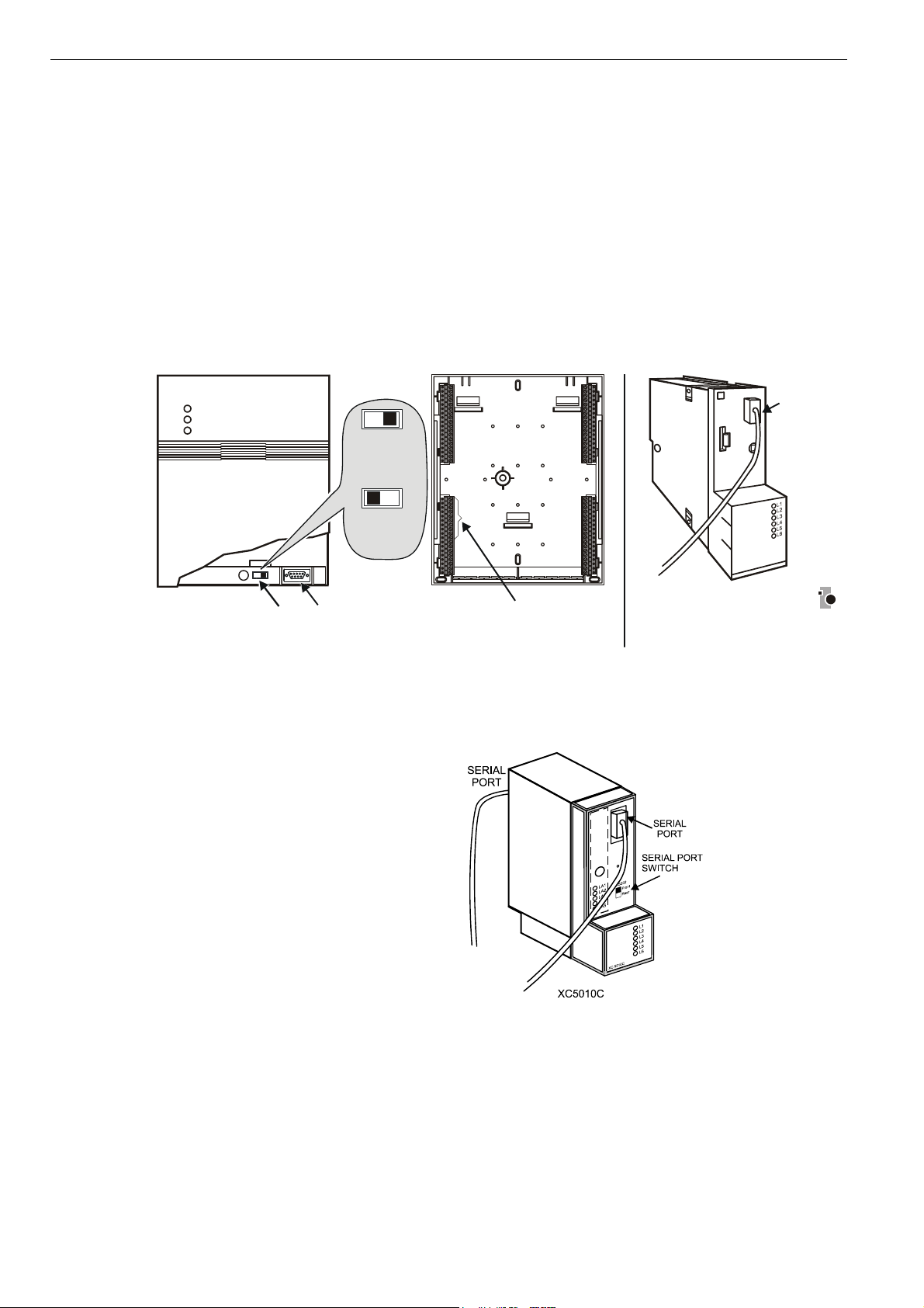
• Excel 100C Controllers have a RS232 serial port connection at the bottom of the
device as shown in the following diagram. An additional serial port connection is
provided at the terminals on the base of the Excel 100C. A port selector switch is
located on the front to select front or rear port (see below).
IMPORTANT
• Excel 500 and 600 Controllers have the serial port connection at the top of the
It is imperative that the Excel 100C Controller’s port selector switch be
properly set. Thus, after having operated an MMI via the front port, the
switch has to be set back to its left position to reactivate a modem being
connected to the rear terminals. If the switch is set to “front port“, the rear
terminals are deactivated, and vice versa.
controller as shown in the following diagram.
FRONT PORT
ACTIVE
SERIAL
PORT
EXCEL 100C
CONNECTION
PORT
SELECTOR
REAR
TERMINALS
ACTIVE
SERIAL
PORT
REAR TERMINALS FOR
MODEM OR MMI CONNECTION
EXCEL 500/600 CONNECTION
Fig. 3. Excel 100C and Excel 500/600 MMI connection
• The XC5010C CPU for Excel 500 has an additional serial port connection at the
terminal block on the back of the unit and a switch on the front to select front or
rear port.
C6982b
Fig. 4. Excel 500-XC5010C MMI connection
• Excel 50 and Excel 500-XCL5010 Controllers require the XW582 cable which
connects to the serial port on the bottom of the device as shown below.
EN2B-0126GE51 R0309 4
Page 9
XI581/XI582 BUSWIDE OPERATOR INTERFACE GETTING STARTED
A
CO
_
EXCEL 50
EXCEL 500-XCL5010
(REAR VIEW)
SERIAL PORT
Fig. 5. Excel 50 and Excel 500-XCL5010 MMI connection
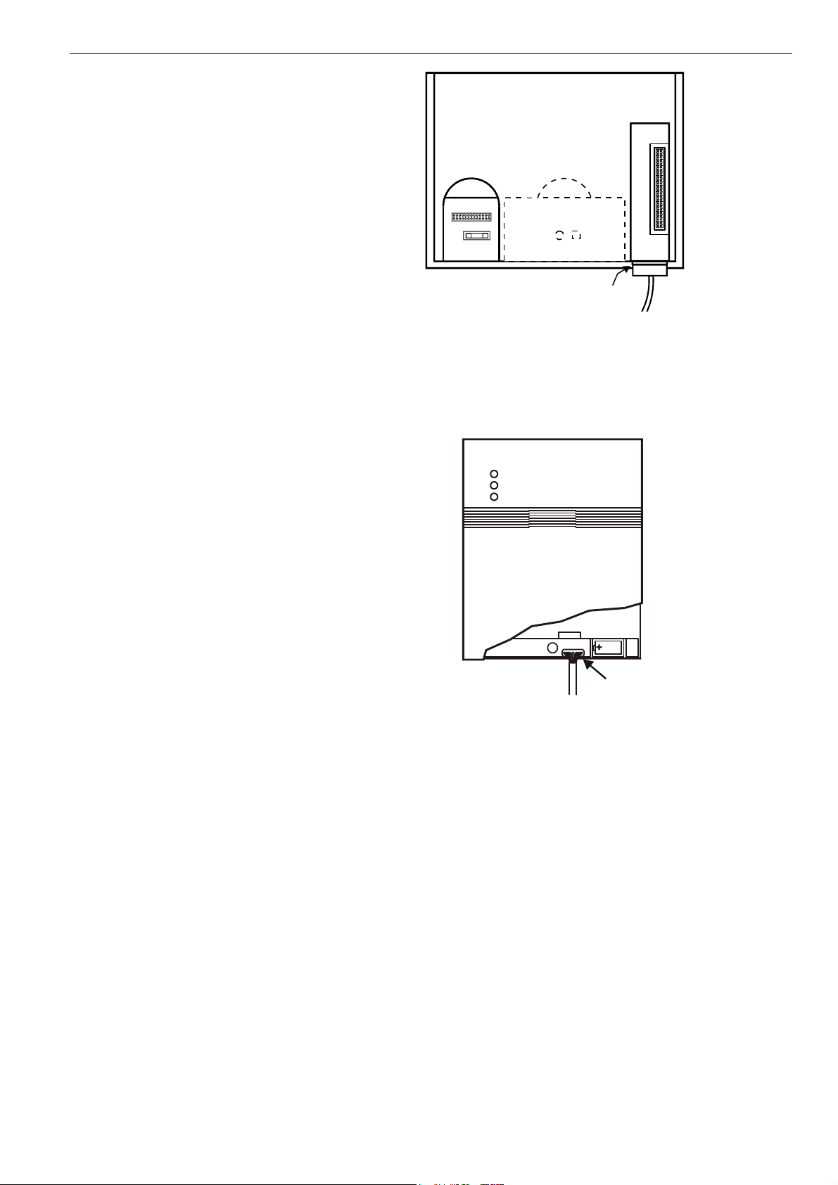
• Excel 10 Zone Manager and Excel 100B Controllers have a serial port connection at the bottom of the device as shown in the following diagram. The
XI581/XI582 reads the data for the Excel 10 Controllers that connect to the Excel
10 Zone Manager.
a
ZM-Con
EXCEL 10
ZONE MANAGER
SERIAL
PORT
ND EXCEL 100B
NNECTION
Fig. 6. Excel 10 Zone Manager and Excel 100B MMI connection
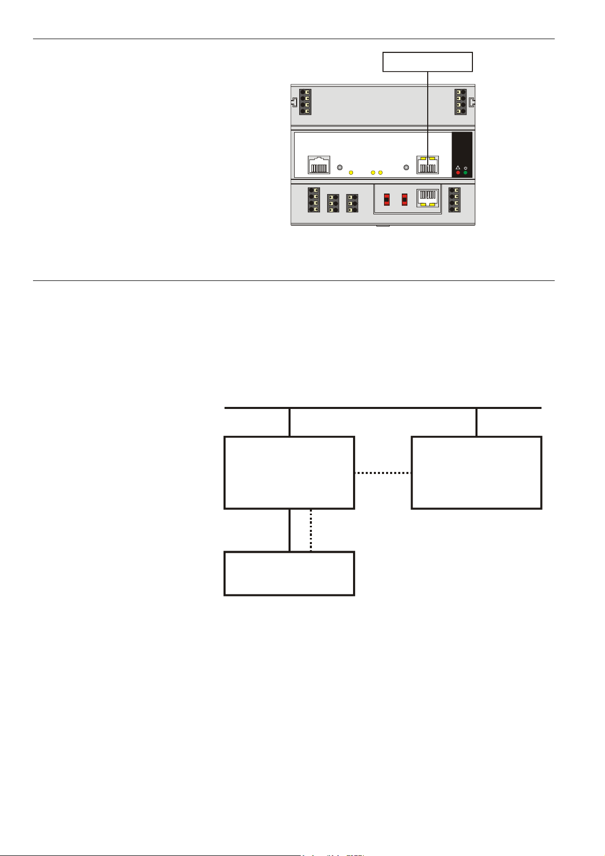
• The Excel 800 Controller Module (XCL8010A) features an RJ45 serial connection
on the front (see Fig. 7) for connection (using the XW882 cable; alternately: the
XW582 together with the XW586) of Human-Machine-Interfaces (HMIs).
5 EN2B-0126GE51 R0309
Page 10
GETTING STARTED XI581/XI582 BUSWIDE OPERATOR INTERFACE
HMI INTERFACE
71 COM a
72 COM b
73 24V
~
74 24V 0
~
LON
87 65 43 21 87 65 43 21
11 1
12 285
13 396
14 410 7
C-Bus
LON
in
C-BUS RESET PC/HMI
C-Bus
out
S1 S2
9.6k
76k
76k
C-Bus
all
mid
end
I/O Bus
Panel
LON
Modem
COM a 75
COM b 76
24V 77
~
24V 0
~ 78
Honeywell
!
87 65 43 21
RxTx
Power/
Alarm
Fig. 7. Excel 800 Controller Module and MMI connection
Buswide Access Mode
The buswide access mode allows communication between an XI581/XI582 and an
Excel controller that is not directly connected to the XI581/XI582. Communication
can include reading from and writing to the remote controller as well as receiving
alarm status information.
For example, an XI581/XI582 attached to an Excel 500 Controller can log in to an
Excel 100 Controller connected to the same system bus as the Excel 500
Controller.
C-bus
local
Excel
controller
remote
Excel
controller
buswide
access
XI581 / XI582
Fig. 8. Buswide access mode
Connection capabilities depend on the version of the controller and whether it has
buswide access mode software. Table 2 specifies the versions capable of the
buswide access mode.
EN2B-0126GE51 R0309 6
Page 11
XI581/XI582 BUSWIDE OPERATOR INTERFACE GETTING STARTED
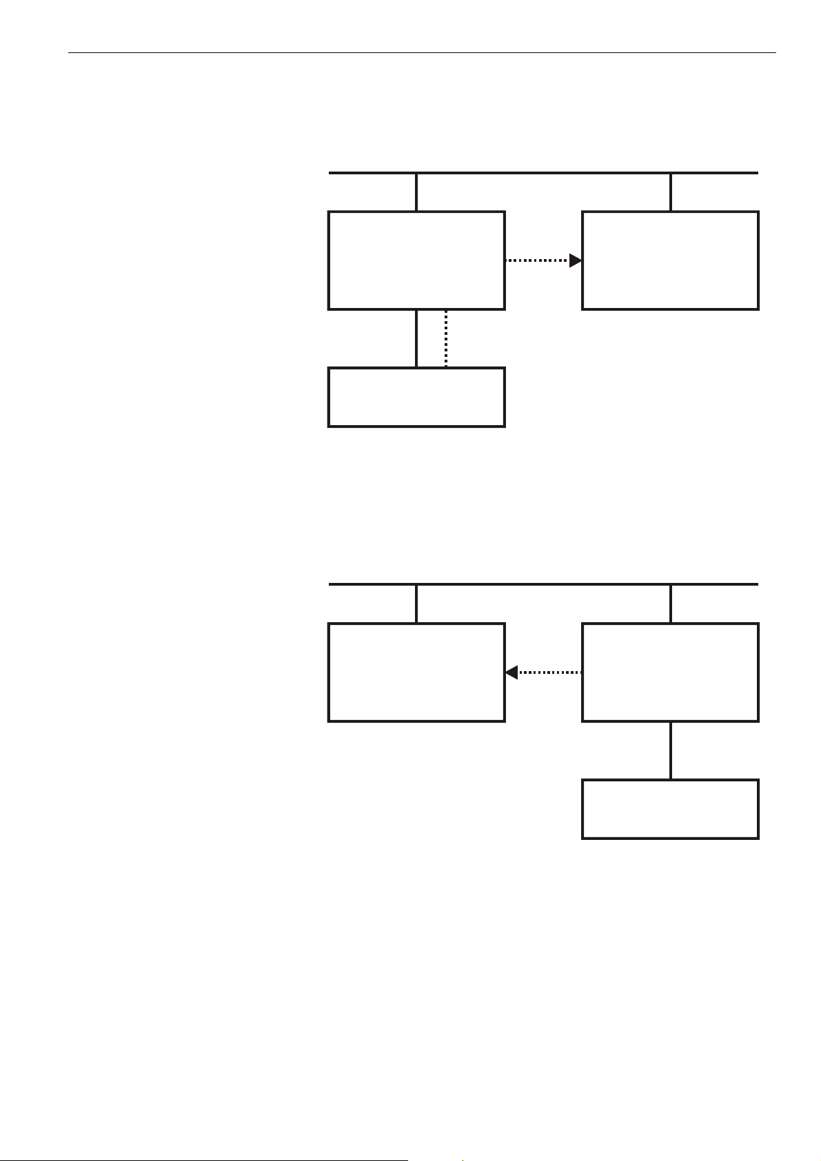
There are two buswide access modes (active and passive) for controllers that have
this capability.
• With active buswide access, a controller (for example, Controller A) can access
another controller (Controller B) on the same bus if Controller B has at least
passive access.
C-bus
Controller A
active
buswide access
Controller B
active or passive
buswide access
buswide
access
XI581 / XI582
Fig. 9. Active buswide access
• With only passive buswide access mode, a controller (for example, Controller B)
cannot access another controller (Controller A) on the same bus. However, since
Controller B has at least the passive buswide access mode, Controller B can be
accessed by another controller that has the active buswide access mode (in this
case, Controller A).
C-bus
Controller A
active
buswide
X
Controller B
passive buswide
access, only
access
XI581 / XI582
Fig. 10. Passive buswide access
To access a remote controller, you must first log in to the controller. Once you are
logged into the remote controller, operation is almost the same as operating a local
controller. The menu structure used for operation is always that of the remote controller.
7 EN2B-0126GE51 R0309
Page 12

GETTING STARTED XI581/XI582 BUSWIDE OPERATOR INTERFACE
You cannot perform the following tasks while in the buswide access mode:
• Set the controller number.
• Set the communication baud rate.
• Start up a new controller.
Controller versions Some controller models (mainly older versions) do not support buswide functionality
or support passive buswide functionality only after installation of a Firmware
EPROM upgrade kit. Please contact your local branch or affiliate for further
information on EPROM upgrade kits.
Table 2. Buswide Access Capability of Different Devices
device buswide access mode
Excel 50, 100, 500, 600,
800 Controller
Yes, with Firmware EPROM Version Excel
500/600/800 1.03.00 or newer.
1
Version 1.01 cannot support the active access mode.
Excel 20 Controller
Excel 10 Zone Manager
Passive buswide access mode, only.
Excel 10 Zone Manager supports the passive buswide
access mode only with Firmware EPROM Version
1.02.xx or newer3.
XIP100 no
1
Excel 100/500/600 Controllers running under Firmware EPROM Version Excel
500/600 1.2.XX can be upgraded by changing the Firmware EPROM to Version
1.03. The controllers then support full buswide functionality, i.e. passive and active
buswide access. Excel 800 controllers support this with any firmware version,
starting with 3.00.xx.
2
Excel 100/500/600 Controllers running under Firmware EPROM Version Excel 500
Version 1.01 must be equipped with the Excel 1.01 upgrade kit for the buswide
access mode. They then support the passive buswide access mode. However,
Version 1.01 Controllers do not support the active buswide access mode.
3
Excel 800 controllers support this with any firmware version, starting with 3.00.xx.
2
Buswide alarms The XI581/XI582 does not directly report buswide alarms on screen, but you can set
it to an “alarm standby” mode where it listens to the system bus and then reports
the occurrence of a new alarm somewhere on the system bus. In a separate
screen, you can view the contents of the alarm buffer which will tell you where on
the system bus the new alarm has occurred. You can then log in to the appropriate
controller and look in the alarm buffer of the remote controller to find the cause of
the alarm.
To enable the buswide alarm flag, set the XI581/XI582 to Alarm Standby Flag mode
in the 'Buswide Access' screen. To enable receiving of buswide alarms, set the
XI581/XI582 to 'Alarm Standby On'. The "Alarm Information" section describes
these options.
When alarm standby is on and the alarm flag enabled, a screen symbol starts
flashing as soon as a new buswide alarm arrives from somewhere on the system
bus.
NOTE: Local alarms will not show when you are logged in to a remote controller.
The reading of a buswide alarm from an XI581/XI582 is independent of the
XBS/XBS-i/XFI/EBI mechanism for alarm acknowledgment.
Performance Only one buswide XI581/XI582 (local or remote) can be logged onto a controller at
any one time. However, there is no restriction as to the total number of buswide
XI581/XI582 used on the same system bus. When XBS PCs are also on the bus,
there may be up to four XBS PCs on the same bus and one buswide XI581/XI582
that is in remote access at the same time.
All XI581/XI582 are of equal priority, so that whichever device signs on first gains
access to a controller and no other device (local or remote) can sign on to the same
controller during this time.
EN2B-0126GE51 R0309 8
Page 13
XI581/XI582 BUSWIDE OPERATOR INTERFACE GETTING STARTED
Screen Displays
Initial screen displays depend on the status of the controller and its pending alarms.
Powered controller After you plug an XI582 into a powered controller, the main menu appears in the
display window.
An XI581 that is always attached to a controller typically displays the main menu
unless an operator has penetrated to some other menu.
Controller power-on The first display screen that appears after power-on is a message about the power
CPU reset If you press the controller's CPU reset switch, the controller restarts and the
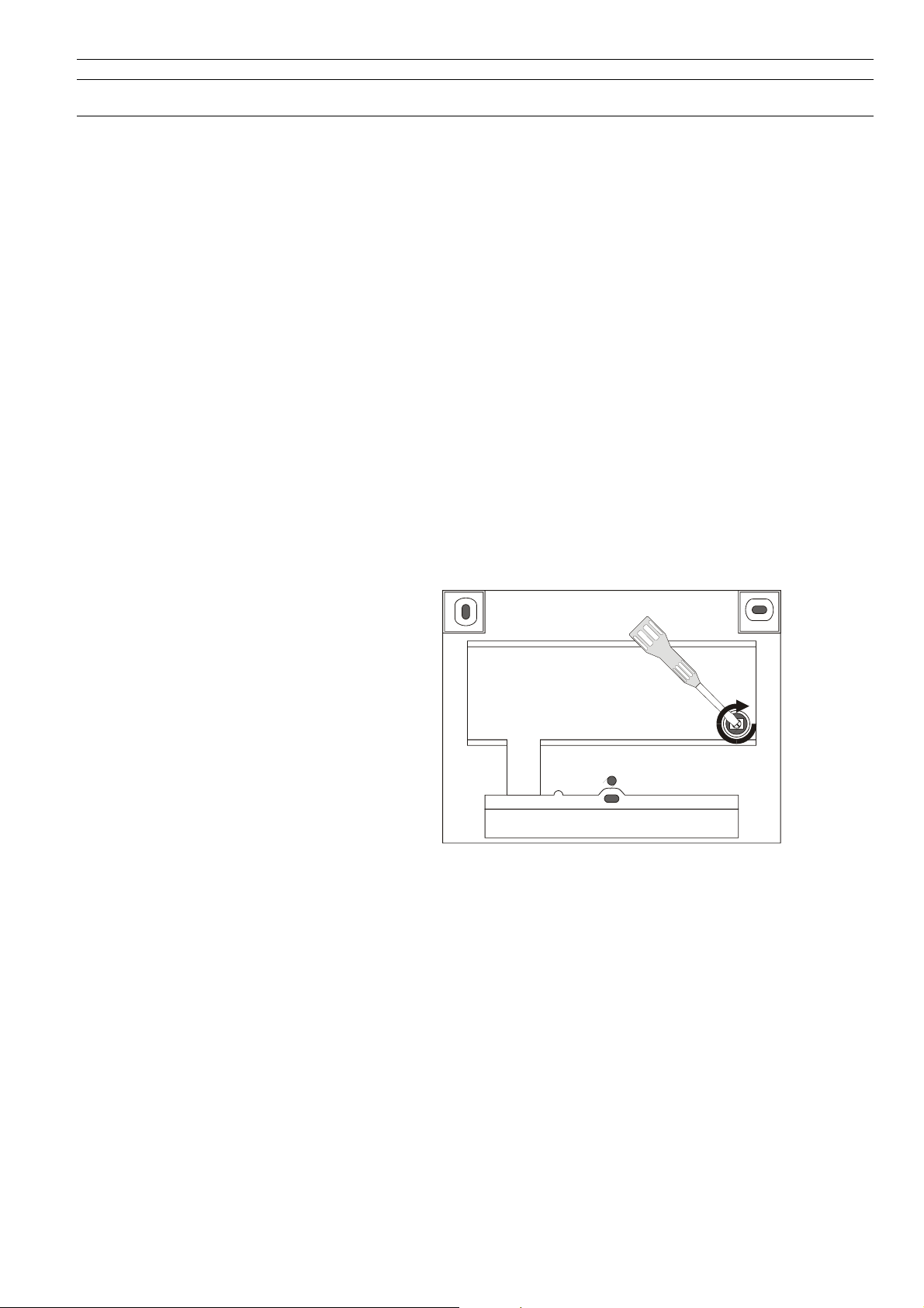
Adjusting contrast The contrast of the display can be adjusted, using a screwdriver, by rotating the
failure. Use the Cancel key (C) to acknowledge the message. The main menu is
displayed.
XI581/XI582 displays the 'title/copyright' screen.
Memory Cleared
If you push the CPU reset switch, everything in the controller is deleted.
Use the CPU reset switch only for servicing.
To reload the controller, follow the download procedure as explained in the Flash
EPROM and RAM Management procedures (in the "ALPHABETIC REFERENCE"
section). If the controller does not have Flash EPROM, use Excel CARE software to
download the controller.
corresponding knob accessible through a hole at the rear of the device. Pressing
any of the eight operating keys activates the backlight. If no entries are made for
approximately ten minutes, the backlight turns itself off automatically until a key is
pressed again.
Operation The rest of this section describes the XI581/XI582 display area and its access
levels. If you are familiar with this information, continue with the sign-on procedure
in the "Local and Remote Sign-On and Sign-Off " section.
9 EN2B-0126GE51 R0309
Page 14
GETTING STARTED XI581/XI582 BUSWIDE OPERATOR INTERFACE
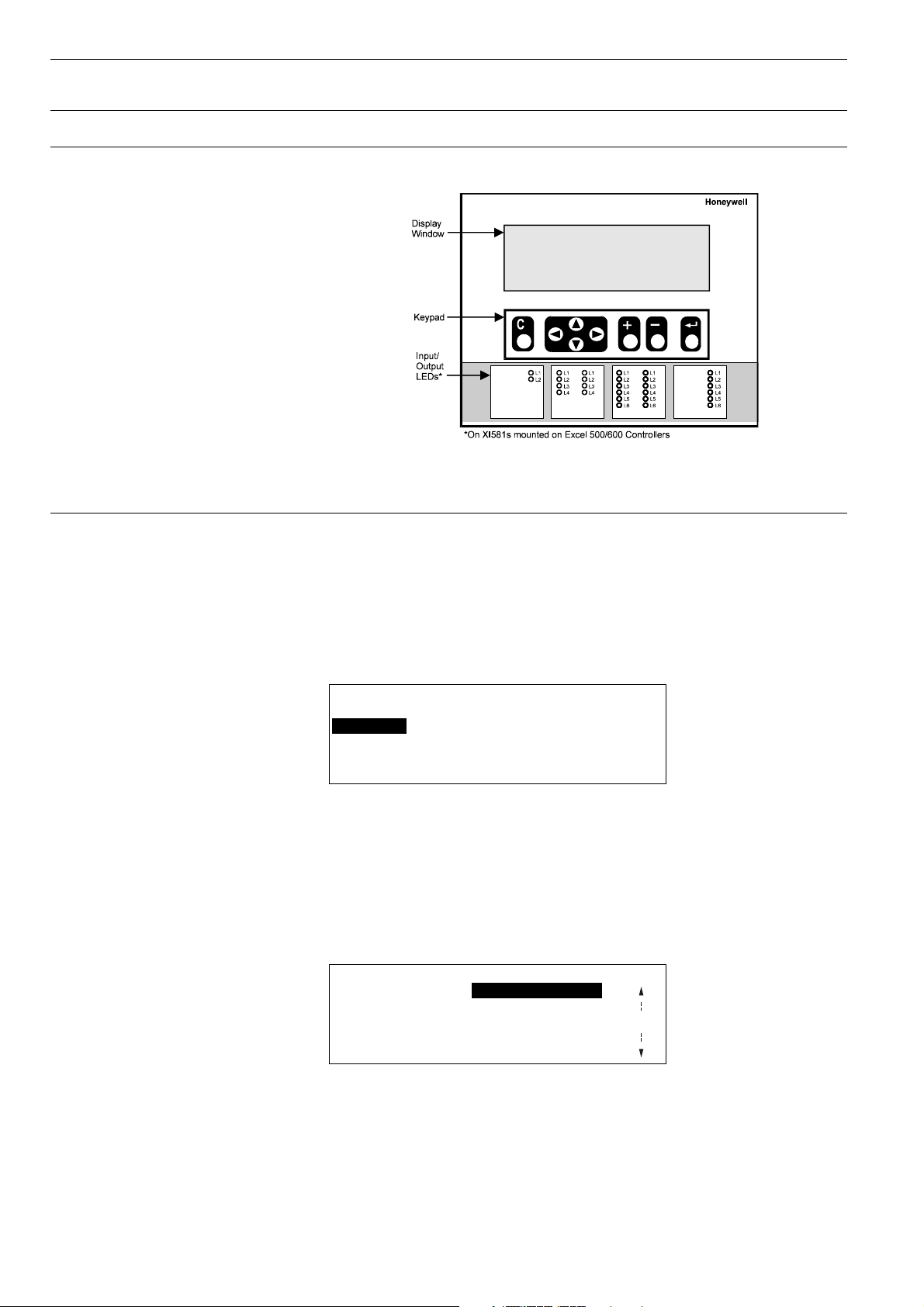
Display Area Description
Fig. 11. MMI display area
Display Window
The XI581/XI582 display window is located above the keypad. The window presents
system information, operator entries, and menus of functions that you can perform.
Menu example For example, the following is the first menu (the main menu) that appears. It shows
the controller name, the current time and date, and a list of functions you can select.
The word Password is highlighted (reverse video on the display) because it is the
default selection.
CONTROLLER_07 18:16!
Running 15.12.1994
Password Alarms
Time Programmes Trend Buffer
Data Points System Clock
System Data
The buswide alarm flag (exclamation mark, !, in the top right-hand corner of the
window) indicates that the buswide alarm notification mode is enabled. If it is
blinking, an alarm has occurred. The "Alarm Information" section describes alarm
display and acknowledgment.
Time program window example The following window display appears when you select 'Time Programmes'. It lists
the zones that have time programs and waits for operator selection of a zone. The
scroll bar is on the right-hand side of the window.
Time Programme
Time Program 1
Ventil. Sys
Lighting 1
Heating zone east
Heating zone west
EN2B-0126GE51 R0309 10
Page 15
XI581/XI582 BUSWIDE OPERATOR INTERFACE GETTING STARTED
Scroll bar The XI581/XI582 display window can show six lines of information at a time. A scroll
bar appears on the right-hand side of the window as shown in the 'Time
Programme' window example:
1
The scroll bar allows you to quickly move through the items in the list so you can
locate the one you want. The number indicates the number of pages being scrolled
using the right and left arrow keys. Use the following keys to scroll (see Table 3).
NOTE: With an Excel 50 directly connected or accessed via the buswide access
mode, the display varies from that given for an Excel 100/500/600
controller. The left two-thirds show the MMI information of the Excel 50; the
right third shows text equivalents of the four fast-access keys of the Excel
50 (see example below).
AHU PLANT
TUE 21:09 11:55 TIME
to 06:00 20.0 C PARAMETERS
TODAY NEXT ALARM
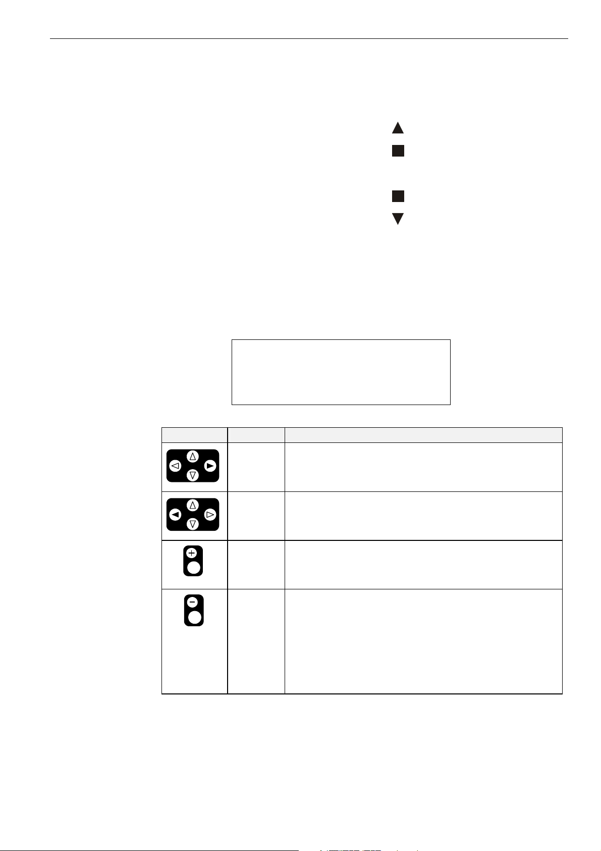
Table 3. Scroll Key Descriptions
key key name scroll description
right arrow
left arrow
C6985
plus
minus
The next section describes the other keys available on the keypad as well as other
functions for the right arrow, left arrow, plus, and minus keys.
Move forward the selected number of pages. See the plus and
minus key descriptions to select the number of pages. The default
is 1 page.
Move backward the selected number of pages. See the plus and
minus key descriptions to select the number of pages. The default
is 1 page.
Increment the number in the scroll bar by 1 (maximum 9). For
example, select 2 to scroll two pages.
After selecting the number of pages, use the right arrow key to
scroll the pages forward.
Decrement the number in the scroll bar by 1.
After selecting the number of pages, use the right arrow key to
scroll the pages backwards.
If you press the minus key while the number in the scroll bar is 1, a
Less-Than symbol (<) appears. If you then press the left arrow key,
the first page in the list will be displayed.
If you press the minus key again while the Less-Than symbol is in
the scroll bar, a Greater-Than symbol (>) appears. If you then
press the right arrow key, the last page in the list will be displayed.
11 EN2B-0126GE51 R0309
Page 16

GETTING STARTED XI581/XI582 BUSWIDE OPERATOR INTERFACE
Keypad
The XI581/XI582 keypad has eight keys that control all operator entries. The
following table describes the function of each key. Following the table are tips for
moving the cursor around within the display window.
Table 4. Description of Key Functions
key key name description
Cancel
left arrow
C6985
right arrow
down arrow
End the task you are performing and return to a previous display
window.
If you press this key after you modify a field, but before pressing
Enter, ↵, the XI581/XI582 erases any new information you input
and retains the original information.
If you press this key after you modify a field and press Enter, ↵, the
XI581/XI582 retains the new information you input.
Within a menu or a line of items, the left arrow moves the cursor
from one column (or item) to another.
Within a data field, the left arrow moves the cursor to the left one
digit.
Within a menu or a line of items, the right arrow moves the cursor
from one column (or item) to another.
Within a data field, the right arrow moves the cursor to the right one
digit.
Move the cursor to the next field, the next column, or to the next
line in a column.
up arrow
Move the cursor to the previous field, the previous column, or to the
previous line in a column.
plus
Increase the value of a digit by one (for example, from 2 to 3). You
can also use this key to change the condition of a digital point. For
minus
example, press this key to flip a digital point from OFF to ON.
Decrease the value of a digit by one (for example, from 2 to 1). You
can also use this key to change the condition of a digital point. For
Enter
example, press this key to flip a digital point from OFF to ON.
Enter and confirm input values or command choices for the
controller. When you press this key, it allow modification of the
highlighted field. Pressing Enter (
↵) again stores the value in
memory.
Moving between columns To move horizontally between columns in a menu or list, press the down arrow key
until you reach the bottom of the column. When you press the down arrow key
again, the cursor automatically jumps to the first item in the next column.
1
If the cursor is on the first item in the first column, pressing the right arrow key
moves the cursor to the first item in the second column. If the cursor is on the last
item in the second column, pressing the down arrow key moves the cursor to the
first item in the first column.
1
NOTE: In case not all entries are displayed (e.g. no password entered), this may
1
differ slightly.
Modifying a field To change information in a field, first use the arrow keys to move to and highlight
the field. Then press Enter, ↵. After the change is made, Enter (↵) must be pressed
again to confirm the change.
EN2B-0126GE51 R0309 12
Page 17

XI581/XI582 BUSWIDE OPERATOR INTERFACE GETTING STARTED
Moving from field to field Once you begin modifying the digits in a field, you can move from digit to digit within
Point order in lists Points are listed according to hardware type. In other words, all analog points
Display of "****" The string "****" means that no value is available.
that field using the arrow keys.
However, to move to a different field, you must press Enter, ↵, after making your
last change to the field. The field is then highlighted. You can then use the arrow
keys to move to and highlight the next field you wish to modify.
appear first, followed by digital points, and finally totalizer points.
Operator Access Levels
There are three access levels that control operator access to XI581/XI582
information. The access levels determine the information an operator can view and
which tasks an operator can perform.
Access level 1 Access level 1 is available to all operators and does not require a password. At level
1, you can view some, but not all, of the information programmed into the controller.
You cannot modify any data. Specifically, access level 1 allows you to view the
following:
• Time program information
• Point descriptions
• System clock
• Trend log
• Alarm information
• Buswide information
Passwords To operate at level 2 or 3, an operator must enter a password. Passwords are four
numerical characters and are controlled by the site administrator. The "Level 2/3
Password Entry" section explains how to enter your password.
Access level 2 Access level 2 allows you to view all information accessible to level-1 operators. In
Access level 3 Access level 3 allows you to perform all tasks accessible to level-1 and level-2
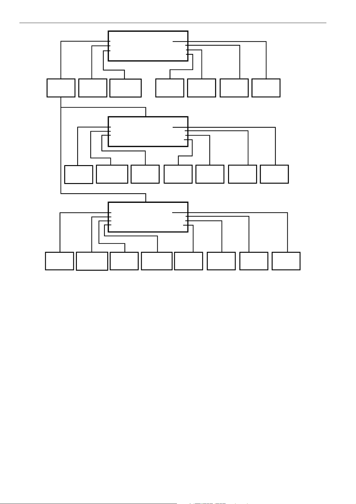
Access level chart The following chart summarizes the functions available at each access level.
addition, you can modify time programs, set the system clock, and view totalizer
information. You can also view and modify information in other controllers on the
same system bus.
operators. In addition, you can:
• Modify point descriptions
• Reset totalizers
• Modify parameters
• Change setpoints
This access level should be reserved for only those users who are responsible and
competent in HVAC engineering, such as a commissioning engineer. This is to
avoid incorrect operation of the plant. This access level is required for setting the
access levels of the other users.
13 EN2B-0126GE51 R0309
Page 18
GETTING STARTED XI581/XI582 BUSWIDE OPERATOR INTERFACE
A
S
OM
ENTER
PASSWORD
PROGRAM
MODIFY
TIME
PROGRAM
VIEW
TIME
DATA POINT
DESCRIPTION
CONTROLLER_01
PASSWORD
TIME PROGRAM
DATA POINTS
VIEW
DATA POINT
DESCRIPTION
CONTROLLER_01
TIME PROGRAM
DATA POINTS
TOTALIZERS
VIEW
CONTROLLER_01
TIME PROGRAM
DATA POINTS
TOTALIZERS
PAR AMET ERS
ALARMS
TREND BUFFER
SYSTEM CLOCK
SYSTEM DATA
ALARMS
TREND BUFFER
SYSTEM CLOCK
SYSTEM DATA
VIEW
TOTALIZERS
ALARMS
TREND BUFFER
SYSTEM CLOCK
SYSTEM DATA
VIEW
SYSTEM
DATA
VIEW BUSWIDE
DATA
VIEW
SYSTEM
DATA
BUSWIDE ACCESS
FLASH EPROM
VIEW
SYSTEM
CLOCK
SET
SYSTEM
CLOCK
CCESS LEVEL 1
LOWEST ACCESS
VIEW
TREND
LOG
ACCESS LEVEL 2
VIEW
TREND
LOG
ACCESS LEVEL 3
HIGHEST ACCESS
VIEW
ALARMS
VIEW
ALARMS
MODIFY
TIME
PROGRAM
MODIFY
DATA POINT
DESCRIPTION
RESET
TOTALIZERS
MODIFY
PARAMETERS
MODIFY
SYSTEM
DATA
BUSWIDE ACCESS
H EPR
FLA
SET
SYSTEM
CLOCK
VIEW
TREND
LOG
Fig. 12. Operator access level and corresponding functions of XI581/XI582
VIEW
ALARMS
C6992-2
EN2B-0126GE51 R0309 14
Page 19

XI581/XI582 BUSWIDE OPERATOR INTERFACE GETTING STARTED
15 EN2B-0126GE51 R0309
Page 20

XI581/XI582 BUSWIDE OPERATOR INTERFACE
EVERYDAY OPERATIONS
About this section This section details steps for common everyday procedures. The procedures are
grouped by common functions as follows.
Local and Remote Sign-on and Sign-off
• Level-2 and level-3 password entry
• Logging into a remote controller
• Logging off from a remote controller
• Signing off from a controller (local or remote)
• Alarm Information
• Viewing alarm information
• Viewing buswide alarms
• Enabling/disabling the buswide alarm mode and alarm flag
• Acknowledging the buswide alarm flag
Viewing point information
Reviewing time program schedules
Requesting a trend log in tabular or graphic format
Listing status of totalizer points
Controller information
• Reading controller date and time
• Viewing controller configuration data
All these procedures, except listing totalizer status, are level-1 operator tasks. The
totalizer function is a level-2 or level-3 operator task.
Any procedures requiring access to a remote controller require log-in to that controller.
Point vs. data point Note that XI581/XI582 refers to points as “data points”. This document uses the
term “point” except when the expression “data point” appears in XI581/XI582 screen
displays. EXCEL 5000™ literature generally uses the term “points”. The terms have
the same meaning.
See also ⇒ the "ALPHABETIC REFERENCE" section (page 49) for other procedures that you
may use less frequently.
Local and Remote Sign-On and Sign-Off
Because the XI581/XI582 is powered whenever the controller it is connected to is
powered, there is no “sign-on” and “sign-off” as for other types of operator terminals.
Typically, when you plug an XI582 into a powered controller, the main menu will be
displayed and you can begin selecting level-1 functions. Alternatively, you can enter
a password to obtain access to level-2 or level-3 functions.
The following are descriptions of the types of screen displays that occur depending
on the status of the controller (powered or reset) and its alarms.
Powered controller When you plug an XI582 into a powered controller, the main menu appears in the
display window.
A XI581 that is always attached to a controller typically displays the main menu
unless an operator has penetrated to some other menu. You can press Cancel (C)
repeatedly until the main menu is displayed.
EN2B-0126GE51 R0308 16
Page 21

XI581/XI582 BUSWIDE OPERATOR INTERFACE EVERYDAY OPERATIONS
Main menu (access level 1)
CONTROLLER_01 18:16!
Running 15.12.1994
Password Alarms
Time Programmes Trend Buffer
Data Points System Clock
System Data
Level 1 operators Level-1 operators do not have to enter a password.
Level 2 & 3 operators Level-2 and level-3 operators must enter a password to perform level-2 and level-3
Controller power-on The first display screen that appears after power-on is a message about the power
Procedures This section describes the following procedures:
operations. See "Level 2/3 Password Entry" (page 17) for details.
failure. Use the Cancel key (C) to acknowledge the message. The main menu will
be displayed.
• Level 2/3 password entry to enter a password if level-2 or level-3 functions are
required
• Logging into a remote controller to gain access to a controller that is not directly
connected to the XI581/XI582
• Logging off from a remote controller to disconnect from a remote controller that
you previously logged into
• Signing off from a controller (local or remote) to return to the level-1 main menu.
Level 2/3 Password Entry
Purpose To sign on to an XI581/XI582 connected to a controller.
Procedure 1. After the XI581/XI582 is connected to a controller, the main menu automatically
appears in the display window unless the controller is reset and needs to be
downloaded. If the controller needs to be downloaded, the 'title/copyright' screen
will be displayed.
NOTE: If the main menu does not appear, press Cancel (C) until it does.
RESULT: The main menu appears and lists information that level-1, -2, and -3
operators can view. The word Password is highlighted as the default
selection.
Level-2 and -3 operators 2.
Level-2 and level-3 operators do not have to enter a password to perform a
level-1 task. However, to perform a level-2 or level-3 task, you must enter a
password using the 'Password' function. Press Enter (↵) to select the 'Password'
function.
NOTE: If the 'Password' function is not highlighted, use the arrow keys to
move to and highlight the item and then press Enter (↵).
RESULT: XI581/XI582 asks for your password. The display window shows four
asterisks where you enter your password.
Please enter your Password:
****
17 EN2B-0126GE51 R0309
Page 22

EVERYDAY OPERATIONS XI581/XI582 BUSWIDE OPERATOR INTERFACE
Password entry 3. Press Enter (↵) to select the password field (four asterisks).
— The display window shows a 5 as the first, left-most digit of the password
field.
— If the first digit of your password is higher than 5, press the plus key (or the
up arrow key) until the first digit of your password is correct.
— If the first digit of your password is lower than 5, press the minus key (or the
down arrow key) until the first digit of your password is correct.
— Use the right arrow key to move the cursor to the second digit. Notice that
the first digit becomes an asterisk again to maintain password privacy.
Repeat this procedure until you have correctly input all digits in the password
field.
If you incorrectly input a digit, press Cancel (C) to start over again with the first,
left-most digit.
Once the password is input, press Enter (↵) to complete password entry. If the
password is incorrect, software re-prompts for password entry.
RESULT: If you correctly enter a password, the word Next will be displayed.
For level-3 operators, the word 'Change' will also be displayed to
allow you to change the password. See the "Passwords" section for
the procedure to change a password.
Please enter your Password:
****
Change Next
Press Enter (↵) to select Next.
Main menu for access level 2
CONTROLLER_01 18:16
Running 15.12.1994
Time Programmes Alarms
Data Points Trend Buffer
Totalizers System Clock
System Data
Main menu for access level 3
CONTROLLER_01 18:16
Running 15.12.1994
Time Programmes Alarms
Data Points Trend Buffer
Totalizers System Clock
Parameters System Data
RESULT: The display window shows the main menu appropriate for the pass-
word you entered.
NOTE: The main menu for access level 2 shows three items ('Time
Programmes', 'Data Points', and 'Totalizers') in the left column, while
the main menu for access level 3 shows four items ('Time
Programmes', 'Data Points', 'Totalizers', and 'Parameters').
5. Select desired function. The rest of this manual contains procedure for each of
EN2B-0126GE51 R0309 18
the functions.
Page 23

XI581/XI582 BUSWIDE OPERATOR INTERFACE EVERYDAY OPERATIONS
Logging into a Remote Controller
Purpose To initiate communication with a remote controller.
Performance Only one buswide XI581/XI582 (local or remote) can be logged onto a controller at
Procedure 1. Sign on to the XI581/XI582 at the desired user level (1, 2, or 3). See section
any one time. However, there is no restriction as to the total number of buswide
XI581/XI582 used on the same system bus. When XBS PCs are also on the bus,
there may be up to four XBS PCs on the same bus and one buswide XI581/XI582
that is in remote access at the same time.
All XI581/XI582 Operator Terminals are of equal priority, so that whichever device
signs on first gains access to a controller and no other device (local or remote) can
sign on to the same controller during this time.
"Level 2/3 Password Entry" (page 17) if you do not know how.
2. At the main menu, use the arrow keys to move to and highlight System Data.
Then press Enter (↵) to complete the selection.
RESULT: The display window shows system data, including the 'Buswide
Access' option. In the following example, note that the local controller
is CONTROLLER_01.
System Data
System Info
HW-Interface Config.
Flash EPROM
Buswide Access
NOTE: The 'Flash EPROM' item will be displayed only if you signed on as a
level-3 operator.
3. Use the arrow keys to move to and highlight Buswide Access. Then press
Enter (↵) to complete the selection.
RESULT: The display window lists the buswide access options you can choose.
Buswide Access
CONTROLLER_01
Remote Login Alarm Standby On
Logoff Alarm Standby Flag
Show All DevicesAlarm Standby Off
The option 'Logoff' appears below 'Remote Login' only if you have
already logged in on the remote controller (i.e. a connection has been
established). 'Logoff' can be used to sever the connection to the
remote controller. See section "Logging Off from a Remote
Controller" (page 21) for details.
4. Press Enter (↵) to select Remote Login (highlighted default).
RESULT: The display window lists all devices available for log-in. Controller
name and number are shown for each device.
Remote Login
CONTROLLER_07 7
CONTROLLER_09 9
1
19 EN2B-0126GE51 R0309
Page 24

EVERYDAY OPERATIONS XI581/XI582 BUSWIDE OPERATOR INTERFACE
5. Use the arrow keys to move to and highlight the name of the desired controller.
Press Enter (↵) to complete the selection.
RESULT: After about 5 seconds, the level-1 main menu of the selected con-
troller will be displayed unless there is a pending alarm. If an alarm is
pending in the remote controller, the alarm will be displayed instead
of the menu. Press Cancel (C) and log in again to see the remote
controller’s main menu.
The following example shows the result of selecting
CONTROLLER_07.
CONTROLLER_07 18:16!
Running 15.12.1994
Password Alarms
Time Programmes Trend Buffer
Data Points System Clock
System Data
Excel 20 and Excel 50 Controllers
6. Press Enter (↵) to select Password.
The operator interface for Excel 20 and Excel 50 Controllers has only four
lines and varies considerably from the screens in this manual. If you log
into a remote Excel 20 or Excel 50 Controller, see the appropriate
Controller User Guide for operator interface description and details.
RESULT: The 'Password' screen will be displayed.
Please enter your Password:
****
Change Next
7. Press Enter (↵) to have the same access level as the local controller. To have a
higher access level, type in your password and press Enter (↵).
RESULT: The main menu of the selected controller will be displayed. The
following example shows level-3 access for CONTROLLER_07.
CONTROLLER_07 18:16
Running 15.12.1994
Time Programmes Alarms
Data Points Trend Buffer
Totalizers System Clock
Parameters System Data
⇒ If the selected device is already being accessed (locally or remotely), the
Buswide alarm flag If the buswide alarm flag was enabled on the local controller, the flag disappears
log-in fails and the system displays the message “Device logged”. Try again
when the device is available.
8. Perform listed tasks as desired just as for a local controller. Log off from the
remote controller when finished (see section "Logging Off from a Remote
Controller", page 21, for details).
after log-in to the remote controller. Set it for the remote controller again to reestablish it, if desired. See section "Alarm Information" (page 22) for procedures.
EN2B-0126GE51 R0309 20
Page 25

XI581/XI582 BUSWIDE OPERATOR INTERFACE EVERYDAY OPERATIONS
Logging Off from a Remote Controller
Purpose To disconnect from a remote controller.
Procedure 1. From the remote controller’s main menu, use the arrow keys to move to and
highlight System Data. Then press Enter (↵) to complete the selection.
RESULT: The display window shows system data, including the 'Buswide
Access' option.
System Data
System Info
HW-Interface Config.
Flash EPROM
Buswide Access
NOTE: The 'Flash EPROM' item will be displayed only if you signed on as a
level-3 operator.
2. Use the arrow keys to move to and highlight Buswide Access. Then press
Enter (↵) to complete the selection.
RESULT: The display window lists the buswide access options you can choose
for remote CONTROLLER_07.
Buswide Access
CONTROLLER_07
Remote Login
Logoff
Show All Devices
3. Use the arrow keys to move to and highlight Logoff. Then press Enter (↵) to
complete the selection.
RESULT: Software logs off CONTROLLER_07 and displays the 'Remote Login'
menu screen to allow you to log in to another controller.
Remote Login
CONTROLLER_07 7
CONTROLLER_09 9
1
4. Select a remote controller to log into or press Cancel (C) to return to the
'Buswide Access' screen for the local controller.
Controller Sign Off
Purpose When you have finished using the XI581/XI582 Operator Terminal to access either
a remote or local controller, sign off so no one else can access the controller at the
same level that you accessed.
Sign-off To sign off, press Cancel (C) until the main menu appears with Password high-
lighted.
21 EN2B-0126GE51 R0309
Page 26

EVERYDAY OPERATIONS XI581/XI582 BUSWIDE OPERATOR INTERFACE
Main menu
CONTROLLER_01 18:16!
Running 15.12.1994
Password Alarms
Time Programmes Trend Buffer
Data Points System Clock
System Data
Auto sign-off If you are signed on to the XI581/XI582 and do not press any keys for 10 minutes,
the operator terminal automatically signs you off.
Alarm Information
This section describes how to view alarm information from the local controller as
well as buswide alarms. For buswide alarms, the section describes how to set the
buswide alarm mode and acknowledge the buswide alarm flag.
Viewing Alarm Information
Purpose To view selected alarm information, including the last 99 alarms, the controller has
generated and stored in memory, all current alarms (critical and non-critical), current
critical alarms, current non-critical alarms, and buswide alarms. All operators can
perform this task.
Select "Alarms" 1. At the main menu, use the arrow keys to move to and highlight the Alarms
option. Press Enter (↵) to complete the selection.
RESULT: The 'View Alarms' screen displays options for viewing alarm
information.
View Alarms
Alarm Buffer
All Points in Alarm
Critical Points in Alarm
Non Critical Points in Alarm
Buswide Alarms
Select desired option 2. Use the arrow keys to move to and highlight the desired option:
EN2B-0126GE51 R0309 22
Page 27

XI581/XI582 BUSWIDE OPERATOR INTERFACE EVERYDAY OPERATIONS
Table 5. Alarm Buffer Options and Alarm Type Options
alarm buffer option alarm type options
Alarm Buffer is highlighted by default when the 'Alarms'
screen is displayed.
Press Enter (↵) to select Alarm buffer.
RESULT: The display window lists all alarms in controller
memory.
Alarm Buffer
19.07.93 16:35 Exhaust_fan
19.07.93 06:26 Cafe_room_temp
18.07.93 23:57 Window_contact_17 1
18.07.93 16:07 Conf_room_temp
17.07.93 20:17 Htg._zone_pump_1
First column—The date the controller generated the alarm.
The date appears in Date.Month.Year (DD.MM.YY)
notation where DD=1-31, MM=1-12, and YY=the last
two digits of the year.
Second column—The time the controller generated the alarm.
The time appears in 24-hour (HH.MM) notation where
HH=00-23 and MM=00-59.
Third column—The user address of the point in alarm.
Press the arrow keys to move to and highlight the desired
option (All Points in Alarm, Critical Points in Alarm, Non
Critical Points in Alarm, or Buswide Alarms). Then press
Enter (↵) to complete the selection.
RESULT: The display window lists points (all, critical, or
non critical) currently in alarm.
All Points in Alarm:
Exhaust_fan
Cafe_room_temp
Window_contact_17 1
Conf_room_temp
Htg._zone_pump_1
NOTE: Alarm memory can contain 99 entries. All alarms
may not be able to appear in the display window at
the same time. To view alarms that do not display,
press the right arrow key to display the next page.
For other scroll bar functions, see the scroll bar
description in the "GETTING STARTED" section.
Select the desired alarm 3. Use the arrow keys to move to and highlight the specific alarm you want to view.
Then press Enter (↵) to complete the selection.
RESULT: The display window shows detailed information about the selected
alarm.
Alarm Buffer
19.07.93 12:03:31
Cafe_room_temp
Alarm Back
CPU not available with
C-Button
Second line Date and time the controller generated the alarm.
Third line User address of the alarm point.
Fourth line State or value of the point at the time the alarm was
generated. If you selected an analog point, this line displays a
value such as a temperature. If you selected a digital point,
this line displays a status such as OFF or ON.
Fifth line Alarm text.
4. Press Cancel (C) to return to the list of alarms.
Viewing Buswide Alarms
Purpose To view new critical and non-critical alarms that occurred on controllers other than
the local controller. You can also view the alarm buffer of a remote controller.
Access level All users can perform this task.
23 EN2B-0126GE51 R0309
Page 28

EVERYDAY OPERATIONS XI581/XI582 BUSWIDE OPERATOR INTERFACE
Requirement To enable viewing of buswide alarms, see section "Enabling/Disabling Buswide
Procedure 1. At the main menu, use the arrow keys to move to and highlight Alarms. Then
Alarm Mode and Alarm Flag" (page 24).
press Enter (↵) to complete the selection.
RESULT: The 'View Alarms' screen will be displayed.
View Alarms
Alarm Buffer
All Points in Alarm
Critical Points in Alarm
Non Critical Points in Alarm
Buswide Alarms
2. Use the arrow keys to move to and highlight Buswide Access. Then press
Enter (↵) to complete the selection.
RESULT: The display window lists all devices available for log-in. Controller
name and number as well as alarm status information list for each
device. The number of the controller appears below 'No'. An 'x'
appears below an alarm header (Critical or Non Critical) to indicate
the presence of an alarm.
Buswide Alarms
Name No Crit Non Crit
CONTROLLER_07 7 x
CONTROLLER_09 9 x x 1
3. Press the arrow keys to move to and highlight the desired controller. Then press
Enter (↵) to complete the selection.
RESULT: You are now logged into the alarm buffer of the selected remote
controller.
4. View the alarm buffer using the same procedure as for a local controller. See
section "Viewing Alarm Information" (page 22) for details if you do not know
how. When you are through reading the buffer, log off the remote controller
(press Cancel repeatedly).
RESULT: Software removes the controller number character from the alarm
buffer to indicate that the alarm(s) were viewed.
Enabling/Disabling Buswide Alarm Mode and Alarm Flag
Purpose To set up XI581/XI582 so that it displays the alarm flag, !, when new buswide
alarms occur.
Access level All users can perform this task.
Procedure 1. At the main menu, use the arrow keys to move to and highlight System Data.
Then press Enter (↵) to complete the selection.
RESULT: The display window show system data, including the 'Buswide
Access' option.
EN2B-0126GE51 R0309 24
Page 29

XI581/XI582 BUSWIDE OPERATOR INTERFACE EVERYDAY OPERATIONS
System Data
System Info
HW-Interface Config.
Flash EPROM
Buswide Access
2. Use the arrow keys to move to and highlight Buswide Access. Then press
Enter (↵) to complete the selection.
RESULT: The display window lists the buswide access options you can choose.
Buswide Access
CONTROLLER_03
Remote Login Alarm Standby On
Alarm Standby Flag
Show All DevicesAlarm Standby Off
3. Use the arrow keys to move to and highlight Alarm Standby On. Then press
Enter (↵) to complete the selection.
RESULT: Software enables buswide alarm mode to enable receiving of
buswide alarms into the buffer (the "Viewing Buswide Alarms" section
describes the procedure).
The 'Buswide Access' screen remains on display.
4. Use the arrow keys to move to and highlight Alarm Standby Flag. Then press
Enter (↵) to complete the selection.
RESULT: The system is set to place the buswide alarm flag, !, in the top right-
hand corner of most other windows.
The 'Buswide Access' screen remains on display.
5. Press Cancel (C) to exit this screen and return to the main menu.
Alarm standby flag example The following level-3 menu shows the exclamation mark, !, in the upper right-hand
corner of the screen.
CONTROLLER_01 18:16!
Running 15.12.1994
Time Programmes Alarms
Data Points Trend Buffer
Totalizers System Clock
Parameters System Data
When an alarm occurs, the flag starts blinking.
Disable buswide alarm notification To disable alarm reporting, follow Steps 1 and 2 in the previous procedure. In Step
3, highlight Alarm Standby Off and press Enter (↵) to complete the selection. The
system removes the flag from all display windows.
Acknowledging the Buswide Alarm Flag
Purpose To notify the system that you saw the notification of a new buswide alarm (blinking
Procedure Use the arrow keys to move to and highlight the alarm flag. Then press Enter (↵) to
exclamation mark, !, in the top right-hand corner of any display window).
complete the selection.
RESULT: The flag stops blinking but remains on display.
25 EN2B-0126GE51 R0309
Page 30

EVERYDAY OPERATIONS XI581/XI582 BUSWIDE OPERATOR INTERFACE
The flag remains as long as buswide alarm notification is enabled.
See section "Enabling/Disabling Buswide Alarm Mode and Alarm
Flag" (page 24) for details.
Viewing Point Information
Purpose To display point information for selected points.
⇒ This procedure details only how to select points by their user addresses and
The "Data Point Description Function" section describes these procedures in
Access level All users can perform this task.
Procedure 1. At the main menu, use the arrow keys to move to and highlight Data Points.
how to display their associated point attributes. There are other options on
the 'Data Points' screen that provide functions to modify point information
and to select points by type or template. If there are many user addresses, it
may be easier to select points by type or template.
detail.
Press Enter (↵) to complete the selection.
RESULT: The display window lists options for viewing point information. User
Address is highlighted by default.
Data Points
User Address Suppress Alarm
Manual Operation Add Template
Accumul. Runtime Delete Template
Type Selection Modify Template
Points in Trend Template Search
NOTE: The 'Add Template', 'Delete Template', and 'Modify Template' items
2. Press Enter (↵) to select User Address.
⇒ The other options on the 'Data Points' screen provide functions to modify
RESULT: The display window lists points (by user address) that you can view.
do not display for level-1 operators, and 'Template Search' appears
only if there are defined templates. If there are no defined templates,
only the 'Add Template' item will be displayed for higher-level
operators so they can define templates.
point information and to select points by type or template. The "Data Point
Description Function" section describes these procedures in detail.
Example:
User Address
Exhaust_fan 1
Hall_main_lights On
Main_water_meter 000 m3 1
Conf_room_temp 23 °C
Select the desired point 3. Use the arrow keys to move to and highlight the point you wish to view. Then
press Enter (↵) to complete the selection.
RESULT: The display window shows detailed information about the selected
point in a series of windows. Most points require three windows to
fully display their attributes. The following example shows the first
window for a digital point.
NOTE: Additional user-defined text for the point may appear on the second
line.
EN2B-0126GE51 R0309 26
Page 31

XI581/XI582 BUSWIDE OPERATOR INTERFACE EVERYDAY OPERATIONS
Htg_zone_pump_1
Status : ON
Operating Mode: AUTO
Trend Logging : OFF
Back Next
To move forward to the next page, highlight Next and press Enter
(↵). To move backward a page, press Cancel (C). To return to the
previous menu, highlight Back, and press Enter (↵).
Second window example:
Htg_zone_pump_1
Technical Address : 010205
Accumulated Runtime : 12736 h
Service Interval : 500 h
Hours Since Serviced: 398 h
Back Next
Third window example:
Htg_zone_pump_1
Last Changed : 15:36 07.06.1993
Cycle Count : 656
Suppress Alarm : NO
Back
The information (or “attributes”) appearing in a point description varies
depending on the type of point you selected (digital, analog, or totalizer). For
more information on the different point descriptions and their attributes, see
section "Data Point Description Function" (page 49).
4. Use the arrow keys to move to and highlight Back and press Enter (↵) to return
to the list of points (by user address). When you are finished, repeatedly press
Cancel (C) to return to the main menu.
See also ⇒ Section "Data Point Description Function" (page 49) for attribute information;
section "Selecting Points by Template" (page 56) for details on the Template search
function;
section "Selecting Points by Point Type" (page 57) for details on the Type search
function.
NOTE: In the case of Excel 800 controllers, the sensor offset cannot be
accessed via the XI581/2; rather, XL-Online must be used, instead.
Reviewing Time Program Schedules
Purpose To display time program equipment start/stop schedules. For an overview of time
Select "Time programmes" 1. At the main menu, use the arrow keys to move to and highlight Time
programs (daily programs, weekly programs, annual programs, the TODAY
program, and the special days program), see section "Time Programs" (page 76).
Programmes. Press Enter (↵) to complete the selection.
RESULT: The 'Time Programme' screen lists available time programs.
27 EN2B-0126GE51 R0309
Page 32

EVERYDAY OPERATIONS XI581/XI582 BUSWIDE OPERATOR INTERFACE
Time Programme
Time Program 1
Ventil. Sys
Lighting 1
Heating zone east
Heating zone west
NOTE: All time programs may not be able to appear in the display window at
the same time.
Select the desired time program 2. Use the arrow keys to move to and highlight the desired time program. Then
press Enter (↵) to complete the selection.
RESULT: The top line of the window displays the selected time program. The
remaining lines display the types of time programs.
Time Programme Time Program 1
Today
Daily Programme
Weekly Programme
Annual Programme
Special Days
Select the desired type of time program 3. Use the arrow keys to move to and highlight the desired type of time program
(such as TODAY) and then press Enter (↵) to complete the selection.
TODAY
Program Lists TODAY program start/stop times.
Daily
Programme Shows a menu to view data, prompts for selection of the
desired daily program, and then displays associated switching
point data.
Weekly
Programme Lists the daily program assigned to each day of the week.
Annual
Programme Prompts for starting date and then displays the daily program
assigned to each day of the year.
Special Days Shows a menu to view data and then lists the daily program
assigned to special days (holidays) of the year.
For more information on the types of time programs, see section "Time
Programs" (page 76).
RESULT: The top line of the display window shows the selected time program.
The remaining lines list time program information or show another
menu depending on the type of time program selected.
4. When you are finished, repeatedly press Cancel (C) to step backwards and
return to the main menu.
Listing Totalizer Status
Purpose To view totalizer information for points.
Access level You must have access level 2 or 3 to perform this task.
Select "Totalizers" 1. At the main menu, use the arrow keys to move to and highlight Totalizers.
EN2B-0126GE51 R0309 28
Press Enter (↵) to complete the selection.
Page 33

XI581/XI582 BUSWIDE OPERATOR INTERFACE EVERYDAY OPERATIONS
RESULT: The display window shows two options for listing totalizer data.
Totalizers
Service Interval
All Totalizers
Service interval Displays a list of digital points and the number of hours.
All Totalizers Displays a list of totalizer points and the value of the units
assigned to them.
Select the desired type of totalizer 2. Use the arrow keys to move to and highlight the type of totalizer you want to
view. Then press Enter (↵) to complete the selection.
RESULT: The display window lists totalizer points.
Service Interval h
Supply_fan 1267s
Exhaust_fan 1257n
Burner 4761
Htg._zone_pump 736n
Cafe._hood 123t
NOTES:
1. All totalizer points may not be able to appear in the display window at
the same time.
2. The appearance of the 'Totalizer' screen differs slightly from that of
the 'Service interval' screen, although they operate the same.
Select the desired totalizer 3. Use the arrow keys to move to and highlight the specific totalizer you want to
view. Press Enter (↵) to complete the selection.
RESULT: The display window shows detailed information about the selected
totalizer.
Service Interval : 1000 h
Supply fan : 1267 h
Reset : Yes/NO
Back
Service interval Number of hours a point can run before the controller
generates a maintenance alarm.
User Address
(Supply fan) Number of hours the point has run since it was last serviced.
The name of this field reflects the name of the totalizer point
you selected.
Reset Zero the totalizer point after service.
NOTE: Additional user-defined text for the point may appear on the second
line.
The "Totalizers" section has more details on totalizer options.
4. When you are finished, repeatedly press Cancel (C) to return to the main menu.
29 EN2B-0126GE51 R0309
Page 34

EVERYDAY OPERATIONS XI581/XI582 BUSWIDE OPERATOR INTERFACE
Requesting a Trend Log
Purpose To request a trend log for a point and view the information in a table or in a graph.
All users can perform this task.
Select "Trend Buffer" 1. At the main menu, use the arrow keys to move to and highlight Trend Buffer.
Press Enter (↵) to complete the selection.
RESULT: The display window lists two options for viewing a trend log.
Trend Buffer
Table
Graph
Select the desired trend log format 2. Choose the desired option for viewing a trend log.
— Table is highlighted by default. Press Enter (↵) to complete the selection.
— Use the arrow keys to move to and highlight Graph. Then press Enter (↵) to
complete the selection.
RESULT: The display window lists points whose activity is recorded in the trend
buffer.
Trend Buffer
Ventilation system
Lighting
Heating zone east 1
Heating zone west
Heating zone north
NOTES:
1. The controller can collect and save trend log data for up to 20 points. The controller’s trend log memory (buffer) can save the latest 200 point change-ofstates. In the case of analog points, a value is saved when the point changes a
specified amount. In the case of digital points and totalizer points, each change
of status is saved.
2. All trend log points may not be able to appear in the display window at the same
time.
Select the desired trend log point 3. Use the arrow keys to move to and highlight the point whose trend log you want
to view. Then press Enter (↵) to complete the selection.
EN2B-0126GE51 R0309 30
Page 35

XI581/XI582 BUSWIDE OPERATOR INTERFACE EVERYDAY OPERATIONS
A
A
Table 6. Trend Log in Tabular and Graph Format
Trend Log in Tabular Format Trend Log in Graph Format
RESULT: The display window shows the trend
RESULT: The display window shows a graph.
log for the selected point in a tabular
format.
Trend Buffer Exhaust_fan
16.07.93 17:45 Switched off
16.07.93 08:30 Switched on
15.07.93 18:30 Switched off 1
15.07.93 13:30 Switched on
15.07.93 12:00 Switched off
26.6
%
18.9
s
n
1
n
t
LARM 19.02.1993 16:40:00
C6993
First column—The date that the point's condition
or value changed. The date appears in
Date.Month.Year (DD.MM.YY) notation
where DD=1-31, MM=1-12, and YY=the
last two digits of the year.
Second column—The time that the point's con-
dition or value changed. The time appears
in 24-hour (HH.MM) notation where
HH=00-23 and MM=00-59.
Third column—A description of the change that
took place.
Maneuver the graph using the following keys:
Key Graph Function
plus Zooms in on graph.
minus Zooms out on graph.
left or right
arrow keys Scrolls graph left or right.
Enter (↵) Switches the trend log from a
graph format to a tabular format.
You can add an additional point to the trend log
graph as long as the two points are different point
types. For example, the first point is an analog
point and the second point is a digital point.
With the graph of the first trend point displayed,
press Cancel (C) to switch back to the list of points
whose activity is recorded in a trend log.
Press the up and down arrow keys to highlight the
additional point whose trend log you want to view.
Then press Enter (↵) to complete the selection.
RESULT: The display window shows the trend
log for the selected points in a graph
format.
26.6
%
18.9
LARM 19.02.1993 16:40:00
C6994
4. Press Cancel (C) to return to the trend log point list. When you are finished,
repeatedly press Cancel (C) to step backwards and to return to the main menu.
31 EN2B-0126GE51 R0309
Page 36

EVERYDAY OPERATIONS XI581/XI582 BUSWIDE OPERATOR INTERFACE
Controller Information
Reading the Controller Clock
Purpose To read the controller date and time and the starting/ending daylight savings times.
Select "System Clock" 1. At the main menu, use the arrow keys to move to and highlight System Clock.
All users can perform this task.
Press Enter (↵) to complete the selection.
RESULT: The display window lists two options for viewing controller clock
information.
System Clock
Date / Time
Daylight Savings
Select the desired clock option 2. Select Date / Time to view controller clock or select Daylight Savings to view
daylight savings time dates as follows:
Table 7. Daylight Savings Time
Date/time Daylight savings time
Date / Time is highlighted by default. Press Enter
(↵) to complete the selection.
RESULT: The display window shows the
current date and time.
Use the arrow keys to move to and highlight
Daylight Savings. Press Enter (↵) to complete the
selection.
RESULT: The display window shows the dates
the controller currently uses to determine when to run on Daylight
Savings Time.
System Clock
Date: 23.07.1993
Time: 13:50
Back
System Clock
Daylight Savings Start: 25.03
End: 30.09
Back
3. Press Enter (↵) to select Back (highlighted by default).
RESULT: The 'System Clock' screen is again displayed.
4. When you are finished, repeatedly press Cancel (C) to return to the main menu.
Viewing Controller Configuration Data
Purpose To view system data for the controller.
Access level All users can perform this task.
Select "System Data" 1. At the main menu, use the arrow keys to move to and highlight System Data.
Press Enter (↵) to complete the selection.
EN2B-0126GE51 R0309 32
Page 37

XI581/XI582 BUSWIDE OPERATOR INTERFACE EVERYDAY OPERATIONS
RESULT: The 'System Data' screen displays four possible options (depending
on access level).
System Data
System Info
HW-Interface Config.
Flash EPROM
Buswide Access
System Info Displays names of project, application, controller and system
version number.
HW-Interface
Config. Provides access to the hardware interface configuration
settings such as baud rates.
Flash EPROM Access to Flash EPROM functions. These functions include
erasing Flash EPROM and saving application data from RAM
to Flash EPROM. See section "Flash EPROM and RAM
Management" (page 65) for details.
Buswide Access Access to buswide access mode functions. These functions
include:
• Display a list of all currently active bus devices (see section
"Viewing Bus Devices", page 97).
• Initiate remote log-in to remote controllers (see section
"Logging into a Remote Controller", page 19).
• Display buswide alarms (see section "Viewing Buswide
Alarms", page 23).
• Enable/disable buswide alarm notification (see section
"Enabling/Disabling Buswide Alarm Mode and Alarm Flag",
page 24)
2. To display more information for a controller, highlight Next and then press Enter
(↵) to complete the selection. The following screen will be displayed.
System Info
Project Name : APPL_4
Applic. Name : CONTROLLER_03
Controller Name: CONTROLLER_03
Burn Date : 01.01.2000 14:30
System Version : V 2.04.01 Next
Project Name Project name given during CARE engineering.
Applic. Name The name of the currently selected application in the
controller.
Controller Name Controller’s system name.
Burn Date Burn date of the application after it is saved in Flash (prior to
that, '00.00.0000 00:00' is displayed; older applications display
blanks).
System Version Versions of the operating system.
3. To display more information for a controller, highlight Next and press Enter (↵).
The following screen displays the tool identification information.
33 EN2B-0126GE51 R0309
Page 38

EVERYDAY OPERATIONS XI581/XI582 BUSWIDE OPERATOR INTERFACE
Tool Identification Data
Name: CARE Version: 3.00.00
User Name:
User ID: xxxxxxxxx-xxxx-xxxx-xxxx
-xxxxxxxxxxxx
Back Next
Tool Name This is the name of the tool used to create the currently loaded
application
Tool Version The version of the tool used to create the current application.
User Name The name of the user who created the current application.
User ID The license number of the tool used to create the current
application.
NOTE: In he case of CARE 4.00.00, there is no value for the "User ID" field.
4. To display more information for a controller, highlight Next and press Enter (↵).
The following screen displays the AMA and ATX file revisions.
Operating Sequence Revision
AMA Revision: 1.16.1.12
ATX Revision: 1.16.1.12
Back
This screen displays the revision numbers for the AMA and ATX files used to create
the operating sequence. Asterisks will appear before and after the AMA revision
number if the AMA or ADS files have been changed before the compilation.
Asterisks will also appear before and after the ATX revision number if the ATX file
has been changed before compilation. 'Back' is preselected to move to the
previous screen. Confirm with ENTER
EN2B-0126GE51 R0309 34
Page 39

XI581/XI582 BUSWIDE OPERATOR INTERFACE
Start-Up and Configuration
Purpose To start up the controller and configure its hardware interfaces.
Reset the controller 1. Reset the controller by pressing the square reset switch on the CPU module.
RESULT: The screen displays system information and version number.
CONTINUE is highlighted by default.
HONEYWELL
E X C E L — 5000
produced in
SCHOENAICH GERMANY
SYSTEM VERSION : V2.03.00
CONTINUE
2. Press Enter (↵) to select CONTINUE.
RESULT: The 'date and time' screen is displayed. Also displayed is whether or
not modem communication is enabled and the size of application
memory. Several start-up options are listed. Controller Setup is
highlighted by default.
01.01.2007 Controller: 23
14:45 Modem Part: inactive
Applic. Mem. Size: 128 KB
Controller Setup
Application Selection
Data Point Wiring Check
Modem Part Shows whether modem communication is enabled for the
controller. Disabling modem communication frees up
additional memory resources. Enabling/disabling modem
communication is performed in a subsequent screen.
Applic. Mem. Size Shows the amount of memory reserved for the application.
Reducing this number frees additional memory resources. The
application memory size is changed in a subsequent screen.
Controller Setup Displays screens for configuring the hardware interfaces for
the controller.
Applic. Selection Loads a user-selected application program from Flash
EPROM to RAM, or permits an application download.
Data Point
Wiring Check Starts a test mode with default data points to allow easy
checkout of input/output wiring.
Change date/time/controller number 3. To modify the date, time, or controller number, use the arrow keys to move to
EN2B-0126GE51 R0308 35
and highlight appropriate field. Press Enter (↵) to complete the selection.
RESULT: The first, left-most digit that you can modify blinks.
4. Use the plus or minus keys to increment or decrement the digit, respectively.
When the digit is correct, use the arrow keys to move to the next digit. Repeat
this procedure until all digits are correct. Press Enter (↵) to complete the
modification. Repeat for any other fields to be modified.
Page 40

EVERYDAY OPERATIONS XI581/XI582 BUSWIDE OPERATOR INTERFACE
Hardware Interface Configuration
5. From the second screen of the Start-up Sequence (shown above), select
Controller Setup and press Enter (↵).
RESULT: A screen appears with a list of hardware interface configuration
options.
HW-Interface Configuration
C-Bus
Lon-Bus 1
B-Port
The contents of this listbox will depend upon the exact hardware configuration of the
controller.
6. Select a hardware interface and press Enter (↵) to continue.
C-Bus
If C-Bus is selected from the 'Hardware Configuration' listbox, the following screen
appears:
C-Bus Configuration
Baudrate : 76800
Controller No.: 23
BACK
7. The 'Baudrate' value field is highlighted by default. Or use the down arrow key to
move to and highlight the 'Controller No.' value field. In either case, after
pressing Enter (↵) to select the given field, one of the digits will begin blinking.
Use the plus and minus keys to increment/decrement data, and press Enter (↵)
to complete the field entry.
NOTE: If you set the bus ID to a non-zero value, the C-bus baudrate will be
NOTE: The bus ID is accessible only in the start-up sequence. After downloading
IMPORTANT
8. Use the right arrow key to move to and highlight BACK. Press Enter (↵).
immediately disabled (i.e. it is then no longer editable). See also section
"LON-Bus" below.
the application, it is hence no longer possible to change the bus ID.
If no controller number is set or if the number shown is not reconfirmed, the
controller will not go online on the C-Bus after start-up.
LON-Bus
If LON-Bus (i.e. LONWORKS network) is selected from the Hardware Configuration
listbox, the following screen appears:
EN2B-0126GE51 R0309 36
Page 41

XI581/XI582 BUSWIDE OPERATOR INTERFACE EVERYDAY OPERATIONS
LON-Bus Configuration
Contr. Neuron ID: ACF123BDE789
Bus ID: 1
BACK
NOTE: The bus ID is accessible only in the start-up sequence. After downloading
the application, it is hence no longer possible to change the bus ID.
The Neuron ID is the unique number assigned to the controller’s processor and
cannot be edited.
Bus ID The bus ID is a non-unique number (i.e. different Excel 500 controllers can have the
same bus ID in common) between 0 and 99 (inclusive) which the user can edit after
a reset during the controller's start-up sequence or (in the case of controllers with
firmware version 2.06.xx) by changing the configuration property
nciXL500BusSetup. The factory default is "0".
Zero value If the bus ID of an Excel 500 controller is set to zero, the C-bus baudrate is enabled
(i.e. editable). Such controllers can communicate not only via the L
but also via C-bus.
Non-zero value If the bus ID of an Excel 500 controller is set to a non-zero value, the C-bus
baudrate is disabled (i.e. non-editable). Such controllers cannot communicate via
the C-bus, but rather only via the L
ONWORKS bus.
ONWORKS bus,
Same non-zero value If the bus IDs of several Excel 500 controllers are set to the same non-zero value,
so-called "C-bus tunneling" is possible. Such controllers can send, via the
L
ONWORKS bus, encapsulated signals containing information of the type which could
otherwise be sent only via the C-bus. In addition to regular L
such controllers can thus communicate schedules, alarms, trends, and dial-ups
among each other; they can also be accessed using a buswide MMI.
7. Press Enter (↵) to select BACK.
ONWORKS messages,
B-Port
If B-Port is selected from the listbox above, the following screen appears to allow
configuration of the serial link used for external user interfaces:
B-Port Configuration
Baudrate: 9600
BACK
7. The 'Baudrate' value field is highlighted by default. After pressing Enter (↵) to
select this field, one of the digits will begin blinking. Use the plus and minus keys
to increment/decrement data, and press Enter (↵) to complete the field entry.
The 'Baudrate' value field will then be highlighted again.
8. Use the right arrow key to move to and highlight BACK. Press Enter (↵).
Modem and Remote Trend Buffer
If 'Modem' is selected from the 'Hardware Configuration' listbox, the following
screen appears:
37 EN2B-0126GE51 R0309
Page 42

EVERYDAY OPERATIONS XI581/XI582 BUSWIDE OPERATOR INTERFACE
Modem Configuration
Configure Modem Interface
Enable Remote Trend Buffer
Configure Remote Trend Buffer
Disable Remote Trend Buffer
For Excel 800:
Modem Configuration
Configure Modem Interface
Enable Remote Trend Buffer
Configure Modem
Interface is always displayed, allows configuration of serial link used for
external modems (highlighted by default).
Enable/Disable Remote
Trend Buffer “Enable” appears if trend buffer is currently disabled. “Disable”
appears only if trend buffer is currently enabled.
Configure Remote
Trend Buffer Appears only if Remote Trend Buffer is currently enabled and
allows entering in new application memory size to make more
memory available for remote trending.
7. Use the arrow keys to move to and highlight a field, and press Enter (↵) to
select the field.
Configuring the Modem Interface
If Configure Modem Interface is selected, the following screen appears:
Modem Configuration
Baudrate: 9600
GSM PIN : ********
Reset Modem BACK
Baudrate Enter the baudrate for the modem interface.
GSM PIN GSM communication is not supported.
Reset Modem Returns modem to factory default settings, erasing any custom
modem initialization. See section "Remote Communication"
(page 70) for more information.
8. To send a reset command to the modem to return it to factory default settings,
use the arrow keys to move to and highlight Reset Modem, and press Enter (↵)
to complete the selection.
9. Use the arrow keys to move to and highlight BACK and press Enter (↵) to
return.
Enabling/Disabling the Remote Trend Buffer
If 'Enable Remote Trend Buffer' or 'Disable Remote Trend Buffer' is selected, the
following screen appears:
EN2B-0126GE51 R0309 38
Page 43

XI581/XI582 BUSWIDE OPERATOR INTERFACE EVERYDAY OPERATIONS
Please be patient
while firmware restarts
RESULT: If either 'Enable Remote Trend Buffer' or 'Disable Remote Trend
Buffer' are selected, the controller restarts with the new memory configuration.
For Excel 800:
HONEYWELL
E X C E L — 5000
produced in
SCHOENAICH GERMANY
SYSTEM VERSION : V2.03.00
CONTINUE
01.01.2007 Controller: 23
14:45 Modem Part: inactive
Applic. Mem. Size: 128 KB
Controller Setup
Application Selection
Data Point Wiring Check
Modem Configuration
Configure Modem Interface
Configure Remote Trend Buffer
Disable Remote Trend Buffer
Configuring the Remote Trend Buffer
If 'Configure Remote Trend Buffer' is selected, the following screen appears:
For Excel 500:
Modem Configuration
Application Memory Size:
128 Kbytes
Remote Trend Buffer
104 Entries
BACK
This screen is used to increase or decrease the size of the adjustable remote trend
buffer. The number of entries (trend samples) that can be stored in the buffer for
Remote Building Central A is determined by a calculation by the controller based
upon the Application Memory Size entered in this screen. This calculation is as
follows: The value entered in this screen is subtracted from the total application
memory, and the resulting number, in Kbytes, represents the amount of memory
available for remote trend buffering. The following figure provides an example for
the adjustable remote trend buffer.
39 EN2B-0126GE51 R0309
Page 44

EVERYDAY OPERATIONS XI581/XI582 BUSWIDE OPERATOR INTERFACE
128
TOTAL APPLICATION MEMORY
UNUSED APPLICATION MEMORY
e.g. 58 KBYTES
REMOTE TREND BUFFER
58 KBYTES
KBYTES
= 1263 ADDITIONAL TREND SAMPLES
APPLICATION
e.g. 70 KBYTES
+ 104 TREND SAMPLES (DEFAULT)
= 1367 T0TAL TREND SAMPLES
Fig. 13. Adjustable remote trend buffer example (Excel 500)
The default for Application Memory Size is the size of total application memory
detected by the controller. The default number of trend buffer entries is 104.
The maximum number of trend samples will be displayed once a value for
Application Memory Size is entered. For a full explanation of this feature of the
controller, see Excel 100/500/600/800 Software Description (EN0B-0092GE51).
NOTE: The minimum Application Memory Size is 38 Kbytes.
7. To increase the size of the buffer, enter a new (lower) value for Application
Memory Size using the cursor keys and confirming with Enter. The controller will
perform a calculation and then display the new number of entries or samples
that the remote trend buffer can hold. After this, RESTART appears highlighted
at the bottom of the screen.
Modem Configuration
Application Memory Size:
58 Kbytes
Remote Trend Buffer:
1360 Entries
RESTART
8. Press Enter (↵) to restart the controller.
IMPORTANT:
If the application being downloaded exceeds the Application Memory Size
entered in this screen, an error message will occur, and the download will
not be executed.
NOTE: Firmware V2.03.01 or later and CARE V2.02.00 or later enable the
controller to run RACL partly from out of the Flash EPROM. Thus, the
application memory calculation is different compared to older versions. This
has to be considered during start up once you enter the application
memory size.
1. CARE V2.02.00 or later:
The maximum application size is 128 Kbytes (128 Kbytes flash memory).
Enter the application size calculated by CARE.
2. CARE versions before V2.02.00 without modem:
The maximum application size calculated by the old CARE is 113 Kbytes
because the complete application including RACL runs from out of the
RAM. The controller will not run if the application is bigger. You need to use
CARE at least V2.02.00 if your applications require more than 113 Kbytes.
Applications bigger than 113 Kbytes without modem will not run out
of flash memory after firmware download of OS V2.03.01 if they were
done with CARE versions before V2.02.00.
3. CARE versions before V2.02.00 with modem:
The maximum application size calculated by the old CARE is 100 Kbytes.
The controller will not run if the application is bigger. For the calculation of
the trend buffer, you need to enter 28 Kbytes plus the application size
calculated by the old CARE version, e.g. CARE V2.02.xx calculated 98
EN2B-0126GE51 R0309 40
Page 45

XI581/XI582 BUSWIDE OPERATOR INTERFACE EVERYDAY OPERATIONS
160
Kbytes, thus you will enter 126 Kbytes (98 Kbytes + 28 Kbytes) on the MMI
of the controller.
We strongly recommend using CARE V2.02.00 or later if you use modem
communication. This will allow for applications with up to 128 Kbytes (128
Kbytes flash memory).
Applications bigger than 100 Kbytes with modem will not run out of
flash memory after firmware download of OS V2.03.01 if they were
done with CARE versions before V2.02.00.
For Excel 800:
Modem Configuration
Application Memory Size:
100 Kbytes
Remote Trend Buffer
2501 Entries
BACK
This screen is used to increase or decrease the size of the adjustable remote trend
buffer. The number of entries (trend samples) that can be stored in the buffer for
Remote Building Central A is determined by a calculation by the controller based
upon the Application Memory Size entered in this screen. This calculation is as
follows: The value entered in this screen is subtracted from the total application
memory, and the resulting number, in Kbytes, represents the amount of memory
available for remote trend buffering. The following figure provides an example for
the adjustable remote trend buffer.
TOTAL APPLICATION MEMORY
REMOTE TREND MEMORY:
60 KBYTES = 2501 TREND ENTRIES
APPLICATION (excluding RACL)
KBYTES
= max. 100 KBYTES
REMOTE TREND BUFFER
60 KBYTES
= 2591 TREND ENTRIES
= 2391 PER FRONT-END A
+ 100 PER FRONT-END B
+ 100 PER FRONT-END C
Fig. 14. Adjustable remote trend buffer example (Excel 800)
Fig. 14 describes the default number of trend entries for a maximum-sized
application.
The maximum number of trend samples will be displayed once a value for
Application Memory Size is entered. For a full explanation of this feature of the
controller, see Excel 100/500/600/800 Software Description (EN0B-0092GE51).
NOTE: The minimum Application Memory Size is 38 Kbytes.
7. To increase the size of the buffer, enter a new (lower) value for Application
Memory Size using the cursor keys and confirming with Enter. The controller will
perform a calculation and then display the new number of entries or samples
that the remote trend buffer can hold. After this, RESTART appears highlighted
at the bottom of the screen.
Modem Configuration
Application Memory Size:
38 Kbytes
Remote Trend Buffer:
3851 Entries
RESTART
41 EN2B-0126GE51 R0309
Page 46

EVERYDAY OPERATIONS XI581/XI582 BUSWIDE OPERATOR INTERFACE
8. Press Enter (↵) to restart the controller.
IMPORTANT:
If the application being downloaded exceeds the Application Memory Size
entered in this screen, an error message will occur, and the download will
not be executed.
Application Selection
Steps 1 and 2 of the Start-up Sequence bring up the following screen:
01.01.2007 Controller: 23
14:45 Modem Part: inactive
Applic. Mem. Size: 128 KB
Controller Setup
Application Selection
Data Point Wiring Check
3. Use the arrow keys to move to and highlight Application Selection and press
Enter (↵) to complete the selection.
RESULT: The first 'Application Selection' screen appears.
Application Selection
Select FLASH Application
Request Download
NOTE: The 'Select FLASH Application' option appears only if there is at least
one application loaded in Flash EPROM.
Select the desired flash application 4. Use the arrow keys to move to and highlight Select FLASH Application and
press Enter (↵) to complete the selection.
RESULT: The display window lists application programs in Flash EPROM with
their burn date and time.
Please choose Fixed Application
APPL_1 23.05.95 10:43 s
APPL_2 17.03.96 17:02 n
APPL_3 11.11.97 23:00 1
APPL_4_NAME_ZU_LA 26.03.98 20:30 n
APPL_5 08.08.98 14.26 t
NOTE: The Flash EPROM can save more than one controller application
Load the desired flash application 5. Use the arrow keys to move to and highlight the desired application program
and then press Enter (↵) to complete the selection.
RESULT: The application program in Flash EPROM loads in RAM and the
program. If two or more application programs have the same name,
the most recently saved application program appears at the bottom of
the list of application programs.
display window shows the main menu (access level 1).
EN2B-0126GE51 R0309 42
Page 47

XI581/XI582 BUSWIDE OPERATOR INTERFACE EVERYDAY OPERATIONS
CONTROLLER_07 18:16
Init 15.12.1994
Password Alarms
Time Programmes Trend Buffer
Data Points System Clock
System Data
Requesting a Download
New applications can be downloaded to the controller’s Flash memory via the CBus or the B-port. The controller must request the download from the device
executing the download. This option is found in the first 'Application Selection'
screen.
Application Selection
Select FLASH Application
Request Download
NOTE: The Select FLASH Application option appears only if there is at
least one application loaded in Flash EPROM.
Select "Request Download" 4. Use the arrow keys to move to and highlight Request Download and press
Enter (↵) to complete the selection.
RESULT: The following screen appears.
Please Execute Download
NOTE: After an application has been downloaded, the controller checks the
CARE application’s user ID and will not start the application if the ID
is invalid. An alarm “Invalid User ID” will be issued (valid for CARE
3.00.00 onwards).
Data Point Wiring Check
Purpose To check out or troubleshoot the system by manually setting outputs and verifying
inputs.
Steps 1 and 2 of the Start-up Sequence bring up the following screen:
01.01.2007 Controller: 23
14:45 Modem Part: inactive
Applic. Mem. Size: 128 KB
Controller Setup
Application Selection
Data Point Wiring Check
3. Use the arrow keys to move to and highlight Data Point Wiring Check and
press Enter (↵) to complete the selection.
43 EN2B-0126GE51 R0309
Page 48

EVERYDAY OPERATIONS XI581/XI582 BUSWIDE OPERATOR INTERFACE
RESULT: The first 'Data Point Wiring Check' screen appears.
Data Point Wiring Check
Default Data Points
DIO Module Assignment
For Excel 800:
Default Data Points
Display Data Points
Alarm History
NOTE: The DIO Module Assignment option appears only if there is a
LonMark™ interface available.
Default Data Points
Purpose To set up the test mode with default user addresses for each of the physical inputs
and outputs.
Select "Default Data Points" 4. From the 'Data Point Wiring Check' screen shown above, select Default Data
Points and press Enter (↵) to complete the selection.
RESULT: The following screen appears with additional options.
Default Data Points
Display Data Points
Alarm History
BACK
Alarm History Displays current alarms.
Display Data Points Displays data points according to point type.
5. Use the arrow keys to move to and highlight Display Data Points and press
Enter (↵) to complete the selection.
RESULT: The display window lists the default data points.
Default Data Points
AI0101 0.0
AI0102 0.0
AI0103 0.0 1
AI0104 0.0
AI0105 0.0
The default user addresses are coded to correspond with the physical I/O in the
following way:
AI0101 — Analog input, board 1, input 1
AO0201 — Analog output, board 2, output 1
DI0301 — Digital input, board 3, input 1
DO0401 — Digital output, board 4, output 1
3P0101 — Motor output, board 1, output 1
EN2B-0126GE51 R0309 44
Page 49

XI581/XI582 BUSWIDE OPERATOR INTERFACE EVERYDAY OPERATIONS
Values are displayed (0/1 for digital points) for each of the default data points, and
the values are refreshed in this screen as they change. Data points related to
Distributed I/O modules will appear in the same way, with module number
appearing instead of board number.
Manually set the desired output 6. Use the arrow keys to move to and highlight desired output and then press
Enter (↵) to complete the selection.
RESULT: The selected output data point is shown with its value/state:
AO0101
STATE/VALUE : 0.0 %
BACK
7. Select 'State/Value' and press Enter (↵) to modify it. Or, select BACK to return
to the 'Data Points' list.
View alarms 8. To view the list of alarms, select Alarm History from the 'Display
Datapoints/Alarm History' screen (Step 4, above).
RESULT: The alarm buffer is shown, listing all system alarms and all changes
of state of inputs: Alarms are generated for changes of state/value on
inputs, which allows shorting and opening the inputs at the switches
and/or sensors and then checking the alarm buffer to verify the
wiring.
17.09.98 16:35 AI0101
17.09.98 16:34 AI0101
17.09.98 16:32 AI0102 1
17.09.98 16:30 AI0102
17.09.98 16:28 AI0103
17.09.98 16:30 AI0104
9. To view an alarm, move the cursor to select the default user address from the
list box using the arrow keys. Confirm with Enter. The following screen will
appear showing date, time, user address, data point value, and alarm text.:
!!! ALARM !!!
16:35:31 17.09.98
AI0101
0.0 BACK
Alarm WITH
C-BUTTON
Press Cancel (C) to return to the previous screen (list of user addresses).
IMPORTANT
After using test options, reset the controller to clear the alarm buffer.
Assigning Distributed I/O Modules
NOTE: In the case of Excel 500 controllers with controller firmware version 2.04.xx,
45 EN2B-0126GE51 R0309
it is possible to assign Distributed I/O modules even after the application
has been downloaded. In the case of controller firmware version 2.06.xx,
however, assignments can be neither performed nor displayed once the
controller firmware has been downloaded (and the options "show" and
"edit" will hence not appear in the corresponding screen).
Page 50

EVERYDAY OPERATIONS XI581/XI582 BUSWIDE OPERATOR INTERFACE
Purpose To assign Distributed I/O modules on LONWORKS networks on which there is more
Select "DIO module assignment" 4. From the 'Data Point Wiring Check' screen shown above (Step 3), use the arrow
than one Excel 500 controller.
NOTE: If there is only one Excel 500 controller on the LONWORKS network,
Distributed I/O modules are assigned automatically.
IMPORTANT
To perform the module assignment in this section, Distributed I/O modules
must be XFL5xxB 2.xx firmware or later.
keys to move to and highlight DIO Module Assignment and press Enter (↵) to
complete the selection.
NOTE: The DIO Module Assignment option appears only if there is a
LonMark™ interface available.
RESULT: The following screen appears with additional options.
DIO Module Assignment
Use existent Assignment
Create new Assignment
Both options will lead to the mask shown below, but with different actions behind
them:
Use existent
Assignment Displays current Distributed I/O module assignments. This
option is displayed only if at least one Distributed I/O module
is already assigned. This option is also used to reactivate /
deactivated assignments.
Create new
Assignment Displays empty listbox with no Distributed I/O modules
assigned. Any existing Distributed I/O assignments will be
cleared.
Select "Use existent Assignment" 5. Use the arrow keys to move to and highlight Use existent Assignment and
press Enter (↵) to complete the selection.
RESULT: The display window lists the Distributed I/O modules on the L
network (up to 16, according to the addresses selected on the
modules’ hex address switches). This screen will be displayed also
when 'Create new Assignment' is selected, but with all addresses
unassigned.
ONWORKS
DIO Module Assignment
02 ? XLF521 0001FC234088
03 <Unassigned> 1
04 <Unassigned>
05 XFL524 0001FC234062
Modules that have been assigned have their module type and Neuron ID displayed
beside them. Special characters indicate the module status according to the
following key:
! An exclamation mark indicates that the module was previously assigned to this
controller in CARE but is now being used by another controller.
- A minus sign indicates that the module is assigned but not yet commissioned.
This is the default state after assignment.
? A question mark indicates that the module is assigned but not available or not
found during commissioning.
EN2B-0126GE51 R0309 46
Page 51

XI581/XI582 BUSWIDE OPERATOR INTERFACE EVERYDAY OPERATIONS
If no special character is seen alongside a module name, this indicates that the
module is correctly assigned and commissioned.
6. To change an assignment, select any line (module address) by using the arrow
keys to move to and highlight it and then pressing Enter (↵). Could also be done
with an assigned module.
RESULT: The display window lists the Distributed I/O module types.
DIO Module Assignment
Address: 04
None
XFL521 1
XFL522
XFL523
7. Select a module type, or None to clear a module assignment, by using the
arrow keys to move to and highlight it and then pressing Enter (↵).
RESULT: If None is selected, the display window lists the previous screen with
this module (here 04) marked as “<Unassigned>”. Module type and
Neuron ID are cleared.
If a specific type is selected, an intermediate mask is displayed, while
the controller searches on the L
the specified module address and module type.
ONWORKS network for all modules with
Please be patient, while
DIO Modules will be searched
After a brief period, the next screen is displayed. The display window
lists all modules of the same type and of the same address. The
search can be canceled by pressing Cancel (C).
DIO Module Assignment
Address: 04
Unassign
! XFL522 0001FC234088 1
XFL522 0001FC334056
* XFL522 0001FC234062
Special characters indicate the module status according to the following key:
! An exclamation mark indicates that the module was previously assigned to this
controller in CARE but is now being used by another controller.
* An asterisk indicates that the module is being used by another controller. It is
displayed because module type and address match.
A blank indicates that this module is free and can be used for assignment.
8. Select a module by using the arrow keys to move to and highlight it and then
pressing Enter (↵).
RESULT: The assignment is accepted and the first 'Distributed I/O Module
Assignment' screen is displayed again.
47 EN2B-0126GE51 R0309
Page 52

EVERYDAY OPERATIONS XI581/XI582 BUSWIDE OPERATOR INTERFACE
DIO Module Assignment
02 ? XLF521 0001FC234088
03 <Unassigned> 1
04 - XFL522 0001FC234088
05 XFL524 0001FC234062
A second method can also be used to select a module. While either the screen with
the Distributed I/O module types (result of step 6) or the screen with the found
Distributed I/O modules (result of step 7) is displayed, press the L
pin of the module being selected.
RESULT: If the L
ONWORKS service pin is pushed, the following screen is
displayed:
ONWORKS service
DIO Module Assignment
Module : 04 XFL522
Neuron ID: 0001FC234088
ASSIGN
9. ASSIGN is highlighted by default. Press Enter (↵) to accept the assignment or
press Cancel (C) to return to the previous screen.
RESULT: If the assignment is accepted, the first 'Distributed I/O Module
Assignment' screen is displayed again.
DIO Module Assignment
02 ? XLF521 0001FC234088
03 <Unassigned> 1
04 - XFL522 0001FC234088
05 XFL524 0001FC234062
IMPORTANT
Distributed I/O module assignments made while in the test mode are saved
in Flash memory.
After loading an application designed to use Distributed I/O modules, these
assignments are used to automatically update the assignments in the
application, but only if module address and module type match. This
update can be inhibited by restarting the controller with the square reset
switch on the CPU module – the assignments done in the test mode are
deactivated and not used to update the assignments in the application.
To reactivate such deactivated assignments, use the option ‘Use existent
Assignment’ in the 'Distributed I/O Module Assignment' screen as shown
above. Then the assignment update is done in the loaded application.
Each time the assignments for a loaded application are changed by the
user, the application should be saved to Flash memory to save these
changes and to guarantee their availability after any controller restart. This
also applies to the test mode during startup.
EN2B-0126GE51 R0309 48
Page 53

XI581/XI582 BUSWIDE OPERATOR INTERFACE ALPHABETIC REFERENCE
ALPHABETIC REFERENCE
This section explains procedures that you do not perform regularly. The procedures
in this section are presented alphabetically so you can quickly and easily find the
one you want. The following procedures are treated:
► Data Point Description function
► Distributed I/O Module Commissioning
► Flash EPROM and RAM Management
► Parameters
► Passwords
► Remote Communication
► System Clock
► Template Operations
► Test Options
► Time Programs
► Totalizers
► View Bus Devices
► View Remote Trend Buffer
Data Point Description Function
Definition A Point Description defines attributes for points. Attributes are descriptive
Point vs. data point Note that XI581/XI582 refers to points as “data points”. This document uses the
Purpose This section first describes how to access the 'Data Point Description' function and
Procedure At the main menu, use the arrow keys to move to and highlight Data Points. Press
information for points and depend on the type of point. For example, analog points
have high and low warning and alarm limits while digital points have runtime values.
term “point” except where “data point” is used in XI581/XI582 screen displays.
EXCEL 5000™ literature generally uses the term “points”. The terms have the same
meaning.
the options in its menu. It then has subsections that describe:
• The display windows that appear when you select a specific point via user
address, template search, or type search
• Point selection and modification via the 'User Address' option
• Point selection and modification via the 'Template Search' option
• Point selection and modification via the 'Type Search' option
• 'Manual Operation' option (manual-to-automatic, only)
• 'Accumulated Runtime' (list only) option
• 'Points in Trend' option (disable trend, only)
• 'Suppress Alarm' option (unsuppress, only)
Enter (↵) to complete the selection.
RESULT: The 'Data Points' screen appears. User Address is highlighted by
default.
Data Points
User Address Suppress Alarm
Manual Operation Add Template
Accumul. Runtime Delete Template
Type Selection Modify Template
Points in Trend Template Search
49 EN2B-0126GE51 R0309
Page 54

ALPHABETIC REFERENCE XI581/XI582 BUSWIDE OPERATOR INTERFACE
Note that the 'Add Template', 'Delete Template', and 'Modify
Template' items do not display for level-1 operators, and 'Template
Search' appears only if there are defined templates. If there are no
defined templates, only the 'Add Template' item will be displayed for
higher-level operators so they can define templates.
Descriptions of each menu item follow.
User Address This option provides a list of available points that you can
select to display point description and modify point attributes.
Example:
User Address
Exhaust_fan 1
Hall_main_lights On
Main_water_meter 000 m3 1
Conf_room_temp 23 °C
You can select one of these points to view and modify its
attributes. See section "Selecting Points by User Address"
(page 55) for details. Note that the following options provide
specific modification functions that are not available via the
User address function.
Manual Operation
Accumul. Runtime
Points in Trend
Suppress Alarm
These options provide a list of points related to the option. For
example, if you select 'Accumul. Runtime', all the points that
have accumulated runtime enabled appear on the screen with
their accumulated hours. Example:
Accumulated Runtime
Supply fan 1267
Exhaust fan 1257
Burner 476 1
Htg. zone pump 736
Cafe. hood 123
Each option displays a different screen with a specific function.
See the relevant sections for details:
Manual Operation Change from manual to automatic operation
Accumul. Runtime List accumulated runtime
Points in Trend Disable a point from trend log
Suppress Alarm (Un)suppress a point’s alarm reporting
To make other changes (for example, to change from
automatic to manual), select the point via the user address,
template search, or type search option.
The Type Selection option provides a list of point types:
EN2B-0126GE51 R0309 50
Page 55

XI581/XI582 BUSWIDE OPERATOR INTERFACE ALPHABETIC REFERENCE
Analog Input Pseudo Analog
Analog Output Pseudo Digital
Digital Input Global Analog
Digital Output Global Digital
Totalizer Flexible Point
Pseudo Totalizer All
You can select a point type to display all the points belonging
to that type. Example:
Analog Input
Cafe_room_temp 23 °C
Conf_room_temp 23 °C
Conf_room_RH 10.0 RH 1
Hallway_temp 23 °C
Reception_temp 23 °C
You can select one of these points to view and modify its
attributes (the same as for the 'User address' option). See
section "Selecting Points by Point Type" (page 57) for details.
The 'Add Template', 'Delete Template', and 'Modify Template' items provide
functions to create new templates and delete or modify existing templates. See
section "Template Operations" (page 72) for details.
The 'Template Search' option provides a list of templates that specify a subset of
points. Example of 'Template Search' screen:
Template Search:
*
*RLT*
*HSG* 1
*KAE*
*NT*
You can select one of these templates to view a list of points
that conform to template specifications. You can then select a
point and view/modify its attributes (the same as for the User
address option). See section "Selecting Points by Template"
(page 56) for details.
See section "Template Operations" (page 72) for a definition
of templates and how to add, modify, and delete them.
Point Description Windows
Description Typically, a Point Description uses some XI581/XI582 display windows to list all
attributes for a point. Next and Back functions allow you to move from one display
window to another.
The following examples illustrate typical point descriptions for a digital point, analog
point, and totalizer point. The table below describes the various point description
attributes. The actual point attributes that display depend on the type of point as
defined in the application program for the controller. See Excel CARE User Guide
for more details about the various types of points and point attributes (in the
"Editors" section).
NOTE: Additional user-defined text may appear on the second line beneath the
user address.
51 EN2B-0126GE51 R0309
Page 56

ALPHABETIC REFERENCE XI581/XI582 BUSWIDE OPERATOR INTERFACE
DIGITAL POINT DESCRIPTION
Htg_zone_pump_1
Status : On
Operating Mode: AUTO
Trend Logging : OFF
Back Next
Htg_zone_pump_1
Technical Address : 010205
Accumulated Runtime : 12736 h
Service Interval : 500 h
Hours Since Serviced: 500 h
Back Next
Htg_zone_pump_1
Normally Closed: Yes
Last Changed : 15:36 19.07.1993
Cycle Count : 656
Suppress Alarm : NO
Back
ANALOG INPUT POINT DESCRIPTION
Conf_Rm_Setpt
Value : 70 F
Operating Mode: AUTO
Back Next
Conf_Rm_Setpt
Technical Address: 010306
Alarm Stat. Chngd: 16:23 23.07.1993
Suppress Alarm : NO
Back Next
Low Alarm Limit : 60.0 F
Low Warning Limit : 54.0 F
High Warning Limit: 74.0 F
High Alarm Limit : 80.0 F
Alarm Hysteresis : 1.0 F
Back Next
Conf_Rm_Setpt
Sensor Offset : 0.0 F
Trend Logging : OFF
Trend Hysteresis : 1.0 Pct
Trend Cycle : 0 min
Back
The engineering units displaed for the values in the examples are degrees
Fahrenheit. If a point is programmed for metric engineering units, the metric units
will be displayed.
EN2B-0126GE51 R0309 52
Page 57

XI581/XI582 BUSWIDE OPERATOR INTERFACE ALPHABETIC REFERENCE
TOTALIZER POINT DESCRIPTION
Main_water_meter
Value : 37530 m3
Operating Mode : AUTO
Trend Logging : On
Back Next
Main_water_meter
Technical Address : 010603
Interval Limit : 1000 m3
Suppress Alarm : No
Back
53 EN2B-0126GE51 R0309
Page 58

ALPHABETIC REFERENCE XI581/XI582 BUSWIDE OPERATOR INTERFACE
Table 8. Typical Point Description Attributes
typical attribute description
User Address
Status Current point status, for example, Off or On. Digital points, only.
Value Point value such as temperature. Analog and totalizer points, only.
Operating Mode
Pulse Duration
Trend Logging
Technical Address
Accumulated
Runtime
Alarm Stat. Chngd. Time and date that the controller last issued an alarm for this point.
Interval Limit
Service Interval How often (in hours) the point should be serviced. Digital points, only.
Hours Since
Serviced
Last Changed
Cycle Count
Suppress Alarm
High and Low
Warning and Alarm
Limits
Time to Open,
Time to Close
Sensor Offset
Trend Hysteresis
Trend Cycle
Alarm Hysteresis Change must exceed this minimum value before an alarm is generated.
Normally Open /
Normally Closed
Descriptive name for the point. The user address can describe the type of
point and/or its physical location.
Whether the point is operated manually or whether the controller operates it
automatically.
Number of energy units the point outputs before it sends a pulse of
information to the controller. Totalizer points, only.
Whether or not the point’s activity (such as the number of times it switches
on and off) is recorded in the trend log.
Numerical address of the point, corresponds to input or output on the board
where the signal is connected.
Number of hours the point has run since it was last serviced. Digital points,
only.
How often (in energy units) the point should be serviced. Totalizer points,
only.
Hours since the point was last serviced. Digital points, only.
Time and date that the status of the point last changed (the last time the
point switched ON or OFF). Digital points, only.
Number of times the point was switched OFF or ON since it was last
serviced. Digital points, only.
Whether the controller reports the alarms it generates for this point. If a point
cannot report, the controller no longer reads its inputs or sets its outputs.
Point value limits. If the point exceeds these limits, the controller generates
an alarm.
Time (in seconds) for an analog output to cycle open or closed. Analog
output points and three-position output points, only.
Offset value that software adds to adjust point value. Analog input points,
only.
Data point value must change positively or negatively by at least this amount
to be written into trend buffer.
Nonzero value enables time-based trending. A value is logged at the interval
specified in Trend Cycle (1440 minutes max.).
Defines relationship between the physical signal of a data point and its
logical status.
See also ⇒ Excel CARE User Guide for more details about the various types of points and point
attributes (in the "Editors" section)
Mapped Points
Some digital and analog points may be mapped to LONWORKS network variables
(NVs) and are not assigned to any I/O board. In this case, the technical address is
zero. The mapped NV of a data point can be displayed as one of the data point
description screens. An example is shown below.
EN2B-0126GE51 R0309 54
Page 59

XI581/XI582 BUSWIDE OPERATOR INTERFACE ALPHABETIC REFERENCE
NV Mapping
User Address Htg_zone_pump_1
Out: 4095 nvoHeatPump
In:
Back
The NV index is shown (0 to 4095) along with the NV name.
Selecting Points by User Address
Purpose To find and display specific user addresses and modify their attributes.
Access level All users can display point information. You must have access level 3 to modify
Select "Data Points" 1. At the main menu, use the arrow keys to move to and highlight Data Points.
point attributes.
Press Enter (↵) to complete the selection.
RESULT: The 'Data Points' screen appears. User Address is highlighted by
default.
Data Points
User Address Suppress Alarm
Manual Operation Add Template
Accumul. Runtime Delete Template
Type Selection Modify Template
Points in Trend Template Search
2. Press Enter (↵) to select User Address.
User Address
Exhaust_fan 1
Hall_main_lights On
Main_water_meter 000 m3 1
Conf_room_temp 23 °C
NOTE: All user addresses for points may not be able to appear in the display
window at the same time.
3. Use the arrow keys to move to and highlight the desired point. Press Enter (↵) to
complete the selection.
RESULT: The display window shows the description of the point you selected.
The information that appears in a point description varies depending
on the type of point you selected (digital, analog, or totalizer). The
table in the beginning of this "Data Point Description" section
describes the various attributes.
Modify attribute of desired point 4. Use the following steps to modify an attribute for the selected point:
a. Use the arrow keys to move to and highlight the field.
b. Press Enter (↵) to select the field.
The field begins blinking and is no longer highlighted.
c. Press the plus or minus keys to toggle or increment/decrement attribute.
d. Press Enter (↵) to complete the entry.
5. When done modifying the point description, press Cancel (C) to return to the
point user address list. When you are finished, repeatedly press Cancel (C) to
return to the main menu.
55 EN2B-0126GE51 R0309
Page 60

ALPHABETIC REFERENCE XI581/XI582 BUSWIDE OPERATOR INTERFACE
Selecting Points by Template
Purpose To find and display points that conform to a template and modify their attributes.
Access level All users can display point information. You must have access level 3 to modify
Select "Data Points" 1. At the main menu, use the arrow keys to move to and highlight Data Points.
point attributes.
Press Enter (↵) to complete the selection.
RESULT: The 'Data Points' screen appears. User Address is highlighted by
default.
Data Points
User Address Suppress Alarm
Manual Operation Add Template
Accumul. Runtime Delete Template
Type Selection Modify Template
Points in Trend Template Search
2. Use the arrow keys to move to and highlight Template Search. Press Enter (↵)
to complete the selection.
RESULT: The 'Templates' screen appears with a list of defined templates.
Template Search:
*
*RLT*
*HSG* 1
*KAE*
*NT*
The 'Add Template', 'Delete Template', and 'Modify Template' items in the
previous screen provide functions to create new templates and delete or modify
existing templates. See section "Template Operations" (page 72) for details.
NOTE: All defined templates may not be able to appear in the display
window at the same time.
3. Use the arrow keys to move to and highlight the desired template. Press Enter
(↵) to complete the selection.
RESULT: The display window lists points you can view along with their values
and engineering units. The list contains only user addresses of points
that match the selected template.
4. Use the arrow keys to move to and highlight the desired point. Press Enter (↵) to
complete the selection.
RESULT: The display window shows the description of the point you selected.
The information that appears in a point description varies depending
on the type of point you selected (digital, analog, or totalizer). The
table in the beginning of this "Data Point Description" section
describes the various attributes.
Modify attribute of desired point 5. Use the following steps to modify an attribute for the selected point:
a. Use the arrow keys to move to and highlight the field.
b. Press Enter (↵) to select the field.
The field begins blinking and is no longer highlighted.
c. Press the plus or minus keys to toggle or increment/decrement attribute.
d. Press Enter (↵) to complete the entry.
EN2B-0126GE51 R0309 56
Page 61

XI581/XI582 BUSWIDE OPERATOR INTERFACE ALPHABETIC REFERENCE
6. When done modifying the point description, press Cancel (C) to return to the
point user address list. When you are finished, repeatedly press Cancel (C) to
return to the main menu.
Selecting Points by Point Type
Purpose To find and display points that belong to a specific point type and modify their
attributes.
Access level All users can display point information. You must have access level 3 to modify
Select "Data Points" 1. At the main menu, use the arrow keys to move to and highlight Data Points.
point attributes.
Press Enter (↵) to complete the selection.
RESULT: The 'Data Points' screen appears. User Address is highlighted by
default.
Data Points
User Address Suppress Alarm
Manual Operation Add Template
Accumul. Runtime Delete Template
Type Selection Modify Template
Points in Trend Template Search
2. Use the arrow keys to move to and highlight Type Selection. Press Enter (↵) to
complete the selection.
RESULT: The 'Types' screen appears with a list of defined point types.
Analog Input Pseudo Analog
Analog Output Pseudo Digital
Digital Input Global Analog
Digital Output Global Digital
Totalizer Flexible Point
Pseudo Totalizer All
3. Use the arrow keys to move to and highlight the desired type. Press Enter (↵) to
complete the selection.
RESULT: The display window lists points you can view. The list contains only
user addresses of points that match the selected type.
4. Use the arrow keys to move to and highlight the desired point. Press Enter (↵) to
complete the selection.
NOTE: All user addresses for points may not be able to appear in the display
window at the same time.
RESULT: The display window shows the description of the point you selected.
The information that appears in a point description varies depending
on the type of point you selected (digital, analog, or totalizer). The
table in the beginning of this "Data Point Description" section
describes the various attributes.
Modify attribute of desired point 5. Use the following steps to modify an attribute for the selected point:
a. Use the arrow keys to move to and highlight the field.
b. Press Enter (↵) to select the field.
The field begins blinking and is no longer highlighted.
c. Press the plus or minus keys to toggle or increment/decrement attribute.
d. Press Enter (↵) to complete the entry.
57 EN2B-0126GE51 R0309
Page 62

ALPHABETIC REFERENCE XI581/XI582 BUSWIDE OPERATOR INTERFACE
6. When done modifying the point description, press Cancel (C) to return to the
point user address list. When you are finished, repeatedly press Cancel (C) to
return to the main menu.
Changing from Manual to Automatic Operation
NOTE: To change a point’s operating mode from automatic to manual, see one of
Purpose To select a point that is currently operating manually, that is, the controller is not
automatically changing it. Change its operating mode to automatic.
Procedure 1. At the main menu, use the arrow keys to move to and highlight Data Points.
the point selection functions (Select Point by User Address, Template
Search, or Type Search).
Press Enter (↵) to complete the selection.
RESULT: The 'Data Points' screen will be displayed.
Data Points
User Address Suppress Alarm
Manual Operation Add Template
Accumul. Runtime Delete Template
Type Selection Modify Template
Points in Trend Template Search
2. Use the arrow keys to move to and highlight Manual Operation and then press
Enter (↵) to complete the selection.
RESULT: The display window lists manually operated points. Example:
Manual Operation
Exhaust_fan
Hall_main_lights
Main_water_meter 1
Conf_room_temp
NOTE: All manually operated points may not be able to appear in the display
window at the same time.
Select the desired point 3. Use the arrow keys to move to and highlight the point whose operation you want
to change from manual operation to automatic controller operation. Press Enter
(↵) to complete the selection.
NOTE: Additional user-defined text may appear on the line beneath the user
address.
RESULT: The display window allows you to change the point’s operating mode
from manual to automatic.
Manual Operation
Exhaust fan
Operating Mode: MANUAL
Back
Change point to automatic operation 4. Use the arrow keys to move to and highlight the Operating Mode field. Then
press Enter (↵) to complete the selection.
RESULT: The entry in the Operating Mode field starts blinking.
5. Press the plus or minus keys to change operating mode to AUTO. Then press
Enter (↵) to complete the change.
EN2B-0126GE51 R0309 58
Page 63

XI581/XI582 BUSWIDE OPERATOR INTERFACE ALPHABETIC REFERENCE
RESULT: The entry in the Operating Mode field stops blinking but is still
highlighted.
6. Use the arrow keys to move to and highlight Back. Then press Enter (↵) to
complete the selection.
RESULT: The 'Data Points' screen is again displayed.
Listing Accumulated Runtime
Purpose To display accumulated runtime information (in hours).
Access level You must have access level 3 to perform this task.
Select "Data Points" 1. At the main menu, use the arrow keys to move to and highlight Data Points.
Press Enter (↵) to complete the selection.
RESULT: The 'Data Points' screen appears. User Address is highlighted by
default.
Data Points
User Address Suppress Alarm
Manual Operation Add Template
Accumul. Runtime Delete Template
Type Selection Modify Template
Points in Trend Template Search
Select "Accumul. Runtime" 2. Use the arrow keys to move to and highlight Accumul. Runtime. Press Enter
(↵) to complete the selection.
RESULT: The display window lists the points and the number of hours each has
run since it was last serviced.
Accumulated Runtime
Supply fan 1267
Exhaust fan 1257
Burner 476 1
Htg. zone pump 736
Cafe. hood 123
NOTE: The hours run for all points may not be able to appear in the display
window at the same time.
3. Press Cancel (C) to return to the list of point description options. When you are
finished, repeatedly press Cancel (C) to return to the main menu.
Disabling a Point from Trend Log
Trend log memory collects and saves up to 200 of the most recent change-of-state
(COS) conditions from up to 20 trend points in a controller. A trend point is a point
that is designated (in the controller’s application program) to report changes in its
state/value to the trend log memory.
Operators can request a trend log report which extracts the trend point COS
information from the trend log memory and outputs the trend information in the
XI581/XI582 display window.
This function disables a point so it cannot contribute associated COS activity to the
trend log memory and it cannot appear in a trend log report output.
NOTE: To enable a point’s trending capability, see section "Selecting Points by
User Address" (page 55).
Purpose To turn off point trending for one or more user addresses.
59 EN2B-0126GE51 R0309
Page 64

ALPHABETIC REFERENCE XI581/XI582 BUSWIDE OPERATOR INTERFACE
Access level You must have access level 3 to perform this task.
Select "Data Points" 1. At the main menu, use the arrow keys to move to and highlight Data Points.
Press Enter (↵) to complete the selection.
RESULT: The 'Data Points' screen appears. User Address is highlighted by
default.
Data Points
User Address Suppress Alarm
Manual Operation Add Template
Accumul. Runtime Delete Template
Type Selection Modify Template
Points in Trend Template Search
Select "Points in Trend" 2. Use the arrow keys to move to and highlight Points in Trend. Press Enter (↵) to
complete the selection.
RESULT: The display window lists points with trending capability.
Points in Trend
Exhaust_fan
Hall_main_lights
Main_water_meter 1
Conf_room_temp
NOTE: All trend points may not be able to appear in the display window at
the same time.
Select the desired point 3. Use the arrow keys to move to and highlight the point you want to disable from
trending. Press Enter (↵) to complete the selection.
NOTE: Additional user-defined text may appear on the line beneath the user
address.
RESULT: The window allows you to disable the point from reporting trend
information.
Points in Trend
Cafeteria_room_temp.
Trend Logging: ON
Back
Disable point from trending 4. Use the arrow keys to move to and highlight the Point in Trend field. Then
press Enter (↵) to complete the selection.
RESULT: The entry in the Point in Trend field starts blinking.
5. Press the plus or minus keys to change the Point in trend to OFF. Then press
Enter (↵) to complete the selection.
RESULT: The entry in the Point in Trend field stops blinking but is still high-
lighted.
6. Use the arrow keys to move to and highlight Back. Then press Enter (↵).
RESULT: The 'Data Points' screen is again displayed.
Suppressing Alarm Reporting for a Point
Purpose To enable/disable alarm reporting for a point.
Access level You must have access level 3 to perform this task.
EN2B-0126GE51 R0309 60
Page 65

XI581/XI582 BUSWIDE OPERATOR INTERFACE ALPHABETIC REFERENCE
Select "Data Points" 1. At the main menu, use the arrow keys to move to and highlight Data Points.
Press Enter (↵) to complete the selection.
RESULT: The 'Data Points' screen appears. User Address is highlighted by
default.
Data Points
User Address Suppress Alarm
Manual Operation Add Template
Accumul. Runtime Delete Template
Type Selection Modify Template
Points in Trend Template Search
Select "Suppress Alarm" 2. Use the arrow keys to move to and highlight Suppress Alarm and then press
Enter (↵) to complete the selection.
RESULT: The display window lists suppressed points.
Suppress Alarm
Exhaust_fan
Hall_main_lights
Main_water_meter 1
Conf_room_temp
NOTE: All suppressed points may not be able to appear in the display
window at the same time.
Select the desired point 3. Use the arrow keys to move to and highlight the point for which you want to
unsuppress alarm conditions. Press Enter (↵) to complete the selection.
NOTE: Additional user-defined text may appear on the line beneath the user
address.
RESULT: The window allows you to unsuppress the point so it can report
alarm information.
NOTE: Regardless as to whether an alarm is suppressed or not, whenever
the alarm occurs, it is written to the alarm buffer. The difference is
that if the alarm is suppressed, it does not display on an operator
interface.
Suppress Alarm
Hall main lights
Suppress Alarm: YES
Back
4. Use the arrow keys to move to and highlight the Suppress Alarm field. Press
Enter (↵) to complete the selection.
RESULT: The entry in the Suppress Alarm field starts blinking and is no longer
highlighted.
5. Press the plus or minus keys to change 'Suppress Alarm' between 'Yes' and
'No'. Press Enter (↵) to complete the selection.
RESULT: The entry in the Suppress Alarm field stops blinking but is still high-
lighted.
6. Use the arrow keys to move to and highlight Back. Press Enter (↵).
RESULT: The 'Data Points' screen is again displayed.
7. Reenter the 'Suppress Alarm' option if you want to verify the change you just
made.
Press Cancel (C) to return to the main menu.
61 EN2B-0126GE51 R0309
Page 66

ALPHABETIC REFERENCE XI581/XI582 BUSWIDE OPERATOR INTERFACE
Assigning Distributed I/O Modules / Showing Assignments
NOTE: In the case of Excel 500 controllers with controller firmware version 2.04.xx,
Purpose To assign Distributed I/O modules whenever there is more than one Excel 500 con-
troller on the L
NOTE: If there is only one Excel 500 controller on the L
IMPORTANT
Access level You must have access level 3 to perform this task.
Select "System Data" 1. At the main menu, highlight System Data and press Enter (↵) to complete the
it is possible to assign Distributed I/O modules even after the application
has been downloaded. In the case of controller firmware version 2.06.xx,
however, assignments can be neither performed nor displayed once the
controller firmware has been downloaded (and the options "show" and
"edit" will hence not appear in the corresponding screen).
ONWORKS network.
ONWORKS network,
Distributed I/O modules are assigned automatically.
To perform the module assignment in this section, Distributed I/O modules
must be XFL5xxB 2.xx firmware or later.
selection.
RESULT: The 'System Data' screen displays four possible options (depending
on access level).
System Data
System Info
HW-Interface Config.
Flash EPROM
Buswide Access
2. Use the arrow keys to move to and highlight HW-Interface. Config. Then press
Enter (↵) to complete the selection. The following screen will be displayed.
HW-Interface Configuration
C-Bus
Lon-Bus 1
B-Port
3. Use the arrow keys to move to and highlight LON-Bus and press Enter (↵) to
complete the selection. The 'LON-Bus' screen is displayed.
LON-Bus Configuration
Contr. Neuron ID: ACF123BDE789
Show DIO Module Assignment
Edit DIO Module Assignment BACK
The Neuron ID is the unique number assigned to the controller’s processor and
cannot be edited.
4. Use the arrow keys to move to and highlight either the Show DIO Module
Assignment or Edit DIO Module Assignment options and press Enter (↵) to
complete the selection.
RESULT: A listbox showing the Distributed I/O modules by address is
displayed. If Show DIO Module Assignment was selected, the
information is displayed only and cannot be modified. If Edit DIO
EN2B-0126GE51 R0309 62
Page 67

XI581/XI582 BUSWIDE OPERATOR INTERFACE ALPHABETIC REFERENCE
Module Assignment is selected, the following warning screen
appears before the listbox screen:
ATTENTION
While next mask is displayed, the
DIO value processing is disabled!
BACK CONTINUE
5. Use the arrow keys to move to and highlight CONTINUE and press Enter (↵) to
complete the selection.
RESULT: The display window lists the all Distributed I/O modules needed for the
loaded applications, even if they are unassigned.
Edit DIO Module Assignment
02 ! XFLF521 0001FC234056
04 ! XFL523 0001FC234088 1
05 XFL522 <Unassigned>
08 XFL524/29 IP-Bus Board
Modules that have been assigned have their module type and Neuron ID displayed
beside them. Special characters indicate the status module according to the
following key:
! An exclamation mark indicates that the module was previously assigned to this
controller in CARE but is now being used by another controller.
- A minus sign indicates that the module is assigned but not yet commissioned.
This is the default state after assignment.
? A question mark indicates that the module is assigned but not available or not
found during commissioning.
If no special character is seen alongside a module name, this indicates that the
module is correctly assigned and commissioned.
NOTE: This screen is refreshed to show changes of state of the modules, such as
if the module is assigned to another controller, the conflict will be displayed.
6. To change an assignment, select any line (module address) by using the arrow
keys to move to and highlight it and then pressing Enter (↵). If a specific module
is selected, an intermediate mask is displayed, while the controller searches on
the L
ONWORKS network for all modules with the specified module address and
module type.
Please be patient, while
DIO Modules will be searched
After a brief period, the next screen is displayed. The display window
lists all modules of the same type and of the same address. The
search can be canceled by pressing Cancel (C).
63 EN2B-0126GE51 R0309
Page 68

ALPHABETIC REFERENCE XI581/XI582 BUSWIDE OPERATOR INTERFACE
Edit DIO Module Assignment
Address: 04
Unassign
! XFL523 0001FC234088 1
XFL523 0001FC334056
* XFL523 0001FC234062
Special characters indicate the module status according to the following key:
! An exclamation mark indicates that the module was previously assigned to this
controller in CARE but is now being used by another controller.
* An asterisk indicates that the module is being used by another controller. It is
displayed because module type and address match.
A blank indicates that this module is free and can be used for assignment.
7. Select a module by using the arrow keys to move to and highlight it and then
pressing Enter (↵).
RESULT: The assignment is accepted and the first 'Distributed I/O Module
Assignment' screen is displayed again.
DIO Module Assignment
02 ? XLF521 0001FC234088
03 <Unassigned> 1
04 - XFL522 0001FC234088
05 XFL524 0001FC234062
Another method to select a module is to press its L
result of step 6 is displayed.
RESULT: If the L
ONWORKS service pin is pushed, the following screen is
displayed:
ONWORKS service pin while the
Edit DIO Module Assignment
Module : 04 XFL523
Neuron ID: 0001FC234088
ASSIGN
8. Assign is highlighted by default. Press Enter (↵) to accept the assignment or
press Cancel (C) to return to the previous screen.
RESULT: If the assignment is accepted, the first 'Distributed I/O Module
Assignment' screen is displayed again.
Edit DIO Module Assignment
02 ! XFLF521 0001FC234056
04 ? XFL523 0001FC234088 1
05 XFL522 <Unassigned>
08 XFL524/29 IP-Bus Board
IMPORTANT
After making any changes to the Distributed I/O module assignments, the
application must be saved to Flash memory so that the application will start
with the same module assignment after any kind of restart.
EN2B-0126GE51 R0309 64
Page 69

XI581/XI582 BUSWIDE OPERATOR INTERFACE ALPHABETIC REFERENCE
Flash EPROM and RAM Management
General Excel controllers contain their application data in RAM. However, RAM is a volatile
form of memory and the information can be lost in a power outage. To ensure the
information is not irretrievably lost, you can save the application data to EPROM
which is a nonvolatile form of memory that retains information without power.
Since the save procedure does not require to physically burn an EPROM, and thus
is relatively quick, the EPROM is called a “Flash” EPROM and the process is called
“flashing” the EPROM.
NOTE: While it is possible to flash additional applications to EPROM without
This section describes the procedures that apply to moving data between Flash
EPROM and RAM:
— Erasing the Flash EPROM
— Saving application in RAM to Flash EPROM
— Restoring application from Flash EPROM to RAM
affecting previously stored applications, it is not possible to erase only
individual applications (for example, to make space for new
applications).
Erasing Flash EPROM
Purpose To clear all application data from Flash EPROM.
Access level You must have access level 3 to perform this task.
CAUTION
The following procedure erases ALL application data in Flash EPROM.
Select "System Data" 1. At the main menu, use the arrow keys to move to and highlight System Data.
Select "Flash EPROM" 2. Use the arrow keys to move to and highlight Flash EPROM. Press Enter (↵) to
Press Enter (↵) to complete the selection.
RESULT: The 'System Data' screen will be displayed with controller name and
software version as well as three possible functions (depending on
access level).
System Data
System Info
HW-Interface Config.
Flash EPROM
Buswide Access
complete the selection.
RESULT: The display window lists options for controlling Flash EPROM.
Flash EPROM
Save Application
Erase Flash EPROM
Show Applications
Select "Erase Flash EPROM" 3. Use the arrow keys to move to and highlight Erase Flash EPROM and then
65 EN2B-0126GE51 R0309
press Enter (↵) to complete the selection.
Page 70

ALPHABETIC REFERENCE XI581/XI582 BUSWIDE OPERATOR INTERFACE
RESULT: The controller begins erasing Flash EPROM and displays the
message: Erasing Flash EPROM, please wait. Erasing the FlashEPROM can take up to 30 minutes depending on the activity of your
application.
When done, the display window lists options for controlling Flash
EPROM. Continue with Step 3 in the procedure for Saving
Application Data in RAM to Flash EPROM.
Erasing a specific application It is not possible to erase one specific application from the EPROM while
maintaining other applications.
Saving Application Data from RAM to Flash EPROM
Purpose To save controller application data from RAM to Flash EPROM.
Access level You must have access level 3 to perform this task.
Select "System Data" 1. At the main menu, use the arrow keys to move to and highlight System Data.
Press Enter (↵) to complete the selection.
RESULT: The 'System Data' screen will be displayed with controller name and
software version as well as three possible functions (depending on
access level).
System Data
System Info
HW-Interface Config.
Flash EPROM
Buswide Access
Select "Flash EPROM" 2. Use the arrow keys to move to and highlight Flash EPROM and then press
Enter (↵) to complete the selection.
RESULT: The 'Flash EPROM' screen lists options for controlling Flash EPROM.
Save Application is highlighted by default.
Flash EPROM
Save Application
Erase Flash EPROM
Show Applications
Save application to flash EPROM 3. Press Enter (↵) to select Save Application.
NOTE: The save procedure writes application data to Flash EPROM. The
save procedure does not affect application data in RAM.
RESULT: If there is sufficient space in the Flash EPROM, the controller begins
saving application data in RAM to Flash EPROM and displays the
message: burning Flash EPROM, please wait.
When done, the display window lists system data.
If the message “Couldn’t burn EPROM” will be displayed, check that
the controller has a Flash EPROM. If it does and there are no
hardware problems, the Flash EPROM is probably out of memory.
Erase the Flash EPROM (previous procedure) and try to save again.
4. Press Cancel (C) to return to the main menu for operator access level 3.
EN2B-0126GE51 R0309 66
Page 71

XI581/XI582 BUSWIDE OPERATOR INTERFACE ALPHABETIC REFERENCE
Showing Application Data in Flash EPROM
Purpose To display controller application data stored in Flash EPROM.
Access level You must have access level 3 to perform this task.
Select "System Data" 1. At the main menu, use the arrow keys to move to and highlight System Data.
Press Enter (↵) to complete the selection.
RESULT: The 'System Data' screen will be displayed with controller name and
software version as well as three possible functions (depending on
access level).
System Data
System Info
HW-Interface Config.
Flash EPROM
Buswide Access
Select "Flash EPROM" 2. Use the arrow keys to move to and highlight Flash EPROM and then press
Enter (↵) to complete the selection.
RESULT: The 'Flash EPROM' screen lists options for controlling Flash EPROM.
Save application is highlighted by default.
Flash EPROM
Save Application
Erase Flash EPROM
Show Applications
Select "Show Applications" 3. Use the arrow keys to move to and highlight Show Applications and then press
Enter (↵) to complete the selection.
RESULT: The display window lists application programs in Flash EPROM with
their burn date and time.
Please choose Fixed Application
APPL_1 23.05.95 10:43
APPL_2 17.03.96 17:02
APPL_3 11.11.97 23:00 1
APPL_4_NAME_ZU_LA 26.03.98 20:30
APPL_5 08.08.98 14.26
NOTE: The Flash EPROM can save more than one controller application
program. If two or more application programs have the same name,
the most recently saved application program appears at the bottom of
the list of application programs.
Restoring Application Data from Flash EPROM to RAM
See section "Application Selection" (page 42).
Parameters
Purpose To view and modify the value of parameters stored in the parameter files.
67 EN2B-0126GE51 R0309
Page 72

ALPHABETIC REFERENCE XI581/XI582 BUSWIDE OPERATOR INTERFACE
Access level You must have access level 3 to perform this task.
Select "Parameters" 1. At the main menu, use the arrow keys to move to and highlight Parameters.
Press Enter (↵) to complete the selection.
RESULT: The display window shows the first parameter file associated with the
controller. Each parameter file represents a group of up to 127
individual parameters.
Parameter File No. : 001
Parameter No. : 001
Parameter Value : 70.00
BACK
NOTE: The controller can contain up to 127 parameters in each of 128
parameter files.
Select a parameter file / parameter 2. Use the arrow keys to move to and highlight the parameter file number or
parameter number within the file shown and press Enter (↵) to edit. Use the plus
and minus keys to increment/decrement data, and press Enter (↵) to complete
the field entry.
RESULT: The display window refreshes with the new parameter file.
Parameter File No. : 002
Parameter No. : 001
Parameter Value : 10.00
BACK
Modify the parameter value 3. Use the arrow keys to move to and highlight the parameter value for the
parameter shown and press Enter (↵) to edit.
RESULT: The last, right-most digit in the Value field blinks, indicating that you
can modify it.
4. Use the plus or minus keys to increment or decrement the digit, respectively.
When the digit is correct, use the arrow keys to move to the next digit. Repeat
this procedure until all digits are correct.
Press Enter (↵) to complete entry in the Value field.
5. To return to the main menu, use the arrow keys to move to and highlight Back.
Press Enter (↵).
Passwords
Purpose To modify an XI581/XI582 password.
Access level You must have access level 3 to perform this task.
Procedure 1. After the XI581/XI582 is connected to a controller, the main menu automatically
appears in the display window.
NOTE: If the main menu does not appear, press Cancel (C) until it does.
RESULT: The main menu appears. Password is highlighted by default so that
level-2 and level-3 operators can enter their passwords.
EN2B-0126GE51 R0309 68
Page 73

XI581/XI582 BUSWIDE OPERATOR INTERFACE ALPHABETIC REFERENCE
CONTROLLER_07 18:16!
Running 15.12.1994
Password Alarms
Time Programmes Trend Buffer
Data Points System Clock
System Data
Level 2 and 3 operators 2. Press Enter (↵) to select the 'Password' function.
NOTE: If the 'Password' function is not highlighted, use the up or down arrow
RESULT: Software asks for your password. The display window shows four
keys to move to and highlight this item and then press Enter (↵) to
complete selection.
asterisks to hide your password when you enter it.
Please enter your Password:
****
3. Press Enter (↵) to select the password field (four asterisks).
— The display window shows a 5 as the first, left-most digit of the password
field.
— If the first digit of your password is higher than 5, press the plus key (or the
up arrow key) until the first digit of your password is correct.
— If the first digit of your password is lower than 5, press the minus key (or the
down arrow key) until the first digit of your password is correct.
— Press the right arrow key to move the cursor to the second digit. Notice that
the first digit becomes an asterisk again to maintain password privacy.
Repeat this procedure until you have correctly entered all digits in the password
field.
NOTES:
1. The default password for level-2 operators is 2222 and the default password
for level-3 operators is 3333.
2. The password for level-3 operators corresponds to the password for Excel
Live CARE. If you change the XI581/XI582 level-3 password, you will
automatically modify the password for Live CARE, too.
4. Press Enter (↵) to complete password entry.
RESULT: Next is highlighted at the bottom of the window.
Please enter your Password:
****
Change NEXT
5. Use the arrow keys to move to and highlight Change and then press Enter (↵).
RESULT: The display window lists the current passwords for level-2 and level-3
operator passwords.
69 EN2B-0126GE51 R0309
Page 74

ALPHABETIC REFERENCE XI581/XI582 BUSWIDE OPERATOR INTERFACE
Change Password
Password Level 2: 2222
Password Level 3: 3333
BACK
Enter new password 6. Use the arrow keys to move to and highlight a password field and press Enter
(↵) to complete the selection.
RESULT: The first, left-most digit of the password field begins blinking.
7. Use the plus or minus keys to increment or decrement password number. Press
the right arrow key to move the cursor to next digit.
Repeat this procedure until you have correctly entered all digits of the new
password.
Press Enter (↵) to complete entry of the new password.
8. Use the up and down arrow keys to move to and highlight Back and press Enter
(↵).
RESULT: The display window shows the main menu.
Remote Communication
Purpose To change baud rate of controller and reset modem.
Access level You must have access level 3 to perform this task.
Select "System Data" 1. At the main menu, use the arrow keys to move to and highlight System Data.
Press Enter (↵) to complete the selection.
RESULT: The 'System Data' screen displays four possible options (depending
on access level).
System Data
System Info
HW-Interface Config.
Flash EPROM
Buswide Access
2. Use the arrow keys to move to and highlight System Info. Then press Enter (↵)
to complete the selection. The following screen will be displayed.
HW-Interface Configuration
C-Bus
Lon-Bus 1
B-Port
3. Use the arrow keys to move to and highlight Modem. Then press Enter (↵) to
complete the selection. The 'Modem Configuration' screen is displayed.
EN2B-0126GE51 R0309 70
Page 75

XI581/XI582 BUSWIDE OPERATOR INTERFACE ALPHABETIC REFERENCE
Modem Configuration
Baudrate: 9600
GSM PIN : ********
Reset Modem NEXT
NOTE: GSM communication is not supported.
4. Modify the modem baud rate by using the arrow keys to move to and highlight
the field, press Enter (↵) to select the field, use the plus and minus keys to
increment/decrement data, and press Enter (↵) to complete the entry.
To send a reset command to the modem to return it to factory default settings,
use the arrow keys to move to and highlight Reset Modem, and press Enter (↵)
to complete the selection.
System Clock
Purpose To modify the controller date/time and define the range of days for Daylight Savings
Access level You must have access level 2 to perform this task.
Select "System Clock" 1. At the main menu, use the arrow keys to move to and highlight System Clock.
Time.
Press Enter (↵) to complete the selection.
RESULT: The 'System Clock' screen lists two options for viewing system clock
information.
System Clock
Date / Time
Daylight Savings
Select system clock option 2. Select Date / Time to change controller clock or select 'Daylight Savings' to set
Daylight Savings Time as follows:
Table 9. Daylight Savings Time (Alphabetic Reference)
Date/time Daylight savings time
Date / Time is highlighted by default. Press Enter
() to complete the selection.
RESULT: The display window shows the current
date and time.
System Clock
Date: 23.07.1993
Time: 13:50
Back
Use the arrow keys to move to and highlight
Daylight Savings. Press Enter () to complete the
selection.
RESULT: The display window shows the dates
the controller currently uses to determine when to run on Daylight Savings
Time.
System Clock
Daylight Savings Start: 25.03
End: 30.09
Back
71 EN2B-0126GE51 R0309
Page 76

ALPHABETIC REFERENCE XI581/XI582 BUSWIDE OPERATOR INTERFACE
Modify the system clock 3. Use the arrow keys to move to and highlight the appropriate field (Date, Time,
Daylight Savings Start, or End). Press Enter (↵) to complete the selection.
RESULT: The first, left-most digit that you can modify blinks.
4. Use the plus or minus keys to increment or decrement the digit, respectively.
When the digit is correct, use the arrow keys to move to the next digit. Repeat
this procedure until all digits are correct.
5. Press Enter (↵) to complete the system clock entry.
Use the arrow keys to move to and highlight the next field for modification. Press
Enter (↵) to complete the selection.
Use the plus and minus keys to change digits as before. Press Enter (↵) to
complete the date or time entry.
6. Use the down arrow key to move to and highlight Back and then press Enter (↵)
to complete the selection.
RESULT: The display window lists the 'System Clock' options.
7. When you are finished, repeatedly press Cancel (C) to return to the main menu.
Template Operations
Template A template is a structure specifying a string of characters to be used for point
Template buffer
Template search
searches. Characters in the template include any that can be used in a user
address as well as special characters such as the asterisk, *, that represents any
number of random characters and the question mark, ?, that represents exactly one
random character.
The template buffer is where defined templates are stored in the controller.
The template search function generates a list of user addresses which match a
specified template. This function helps you to filter a small set of user addresses out
of the total set of user addresses in large applications.
For example, a template string such as FLOOR1* can concentrate the search for all
user addresses related to the first floor of a building:
FLOOR1_TEMP
FLOOR1_RH
FLOOR1_PRESS
FLOOR1_FAN
Adding a Template
Purpose To add a new template to the template buffer of your application. You create new
Access level You must have access level 2 or 3 to perform this task.
templates by modifying existing user addresses.
Select "Data Points" 1. At the main menu, use the arrow keys to move to and highlight Data Points.
Press Enter (↵) to complete the selection.
RESULT: The 'Data Points' screen will be displayed.
Data Points
User Address Suppress Alarm
Manual Operation Add Template
Accumul. Runtime Delete Template
Type Selection Modify Template
Points in Trend Template Search
EN2B-0126GE51 R0309 72
Page 77

XI581/XI582 BUSWIDE OPERATOR INTERFACE ALPHABETIC REFERENCE
Select "Add Template" 2. Use the arrow keys to move to and highlight Add Template. Press Enter (↵) to
complete the selection.
RESULT: The window shows all user addresses in the current controller
applications. Example:
Add Template
FLOOR1_TEMP
FLOOR1_RH
FLOOR1_PRESS 1
FLOOR1_FAN
FLOOR1_LITES
Select a basic string 3. Use the down arrow key to select the basic string that most closely matches the
template you want to create. For example, if you want to create the template
FLOOR1_ to find all user addresses beginning with the characters FLOOR1_,
select any of the strings that begin with FLOOR1_, for example,
FLOOR1_TEMP. Press Enter (↵) to complete the selection.
RESULT: Software copies the selected basic string into the modify field. The
screen display changes to show your selection.
Add Template
FLOOR1_TEMP
Store Template Back
Select a string 4. Press Enter (↵).
RESULT: The first character in the string is now blinking.
Position the cursor 5. Use the left and right arrows to position the cursor at the character where you
want to modify the string.
RESULT: The selected character is now blinking and can be edited.
Replace a character 6. Use the plus and minus keys to choose the character that you want to use to
Question mark
? Match exactly one character of any type.
Asterisk * Match any number of characters until the next occurrence of a
Blank Delete the selected character after using the right arrow. Or
Cut-off string If you select two asterisks in a row, **, all characters to the
replace the blinking character. Each time you press the plus/minus key, the
blinking character changes through a pattern of ?, *, a blank, and then back to
the original character.
Stop at the desired character. Repeat for each character you want to change.
RESULT: The template will be displayed as created. For example:
character that must be matched exactly.
replace with the original character by pressing Enter (↵).
right are automatically cleared.
Add Template
FLOOR1_TEMP
Store Template Back
73 EN2B-0126GE51 R0309
Page 78

ALPHABETIC REFERENCE XI581/XI582 BUSWIDE OPERATOR INTERFACE
Select "Store Template" 7. Press Enter to highlight the newly created string. Use the arrow keys to move to
and highlight Store Template. Press Enter (↵) to complete the selection.
Or, if you do not wish to save the template, exit by pressing Cancel (C) before
selecting 'Store Template'. If you already stored the template, use the 'Delete a
Template' function.
RESULT: The new template is added to the template list shown on the display.
Example:
Add Template
FLOOR7*
FLOOR1*
1
New Template
Back
Select "New Template" 8. To create another template, highlight New Template and then press Enter (↵) to
complete the selection. Or, to return to the 'Data Points' screen, highlight Back
and press Enter (↵).
Deleting a Template
Purpose To delete a template from the template buffer.
Access level You must have access level 2 or 3 to perform this task.
Procedure 1. At the main menu, use the arrow keys to move to and highlight Data Points.
Press Enter (↵) to complete the selection.
RESULT: The 'Data Points' screen will be displayed.
Data Points
User Address Suppress Alarm
Manual Operation Add Template
Accumul. Runtime Delete Template
Type Selection Modify Template
Points in Trend Template Search
Select "Delete Template"
2. Use the arrow keys to move to and highlight Delete Template. Press Enter (↵)
to complete the selection.
RESULT: The window shows a list of available templates.
Delete Template
FLOOR7*
FLOOR1*
1
Select the desired template 3. Use the arrow keys to move to and highlight the template you want to delete.
Then press Enter (↵) to complete the selection.
RESULT: Software deletes the template. The window displays the list of
remaining templates.
4. Press Cancel (C) to return to the Data Points display.
EN2B-0126GE51 R0309 74
Page 79

XI581/XI582 BUSWIDE OPERATOR INTERFACE ALPHABETIC REFERENCE
Modifying a Template
Purpose To modify an existing template in the template buffer.
Access level You must have access level 2 or 3 to perform this task.
Procedure 1. At the main menu, use the arrow keys to move to and highlight Data Points.
Press Enter (↵) to complete the selection.
RESULT: The 'Data Points' screen will be displayed.
Data Points
User Address Suppress Alarm
Manual Operation Add Template
Accumul. Runtime Delete Template
Type Selection Modify Template
Points in Trend Template Search
Select "Modify Template" 2. Use the arrow keys to move to and highlight Modify Template. Press Enter (↵)
to complete the selection.
RESULT: The 'Modify Template' screen shows a list of available templates.
Modify Template
FLOOR7*
FLOOR1*
1
Select the desired template 3. Use the arrow keys to move to and highlight the template you want to modify.
Then press Enter (↵) to complete the selection.
RESULT: The 'Modify Template' screen displays the selected template.
Modify Template
FLOOR1*
Store Template Back
Select a string 4. Press Enter.
RESULT: The first character in the string is now blinking.
Position the cursor 5. Use the left and right arrows to position the cursor at the character where you
want to modify the string.
RESULT: The selected character is now blinking and can be edited.
Replace a character 6. Use the plus and minus keys to choose the character that you want to use to
replace the blinking character. Each time you press the plus/minus key, the
blinking character changes through a pattern of ?, *, a blank, and then back to
the original character.
Question mark
? Match exactly one character of any type.
Asterisk * Match any number of characters until the next occurrence of a
75 EN2B-0126GE51 R0309
character that must be matched exactly.
Page 80

ALPHABETIC REFERENCE XI581/XI582 BUSWIDE OPERATOR INTERFACE
Blank Delete the selected character after you press the right arrow.
Or, replace with the original character if you press Enter.
Cut-off string If you select two asterisks in a row, **, all characters to the
right are automatically cleared.
Stop at the desired character. Repeat for each character you want to change.
RESULT: The template will be displayed as changed. For example:
Modify Template
FLOOR1?
Store Template Back
Select "Store Template" 7. Press Enter to highlight the string. Use the arrow keys to move to and highlight
Store Template. Press Enter (↵) to complete the selection.
Or, if you do not wish to save the changes, exit by pressing Cancel (C) before
selecting 'Store Template'. If you already stored the template, use the 'Delete a
Template' function.
RESULT: The changed template is added to the template list shown on the
display. Example:
Modify Template
FLOOR7*
FLOOR1?
1
8. Select another template and press Enter (↵) to modify it. Or, press Cancel (C) to
return to the 'Data Points' screen.
Test Options
Purpose To checkout or troubleshoot the system by manually setting outputs and verifying
inputs. See section "Default Data Points" (page 44).
Time Programs
General Excel controllers allow equipment control based on time of day. For example, you
can set HVAC equipment start and stop times. Time programs implement this
control strategy. Each controller can have a maximum of 20 time programs.
The following figure illustrates a time program that controls lighting in a school.
Each time program specifies one weekly program. This weekly program schedules
the normal daily activity of the system by specifying which daily programs an Excel
controller should use for each day of a normal week (Sunday through Saturday).
Daily programs list points and point actions for the Excel controller to execute. The
points and point actions are called switch points. Daily programs with their switch
points are assigned to weekly programs to provide for automatic operations on
scheduled days.
An annual program applies the weekly program to each week of the year. The
controller operates according to the annual program.
To accommodate special events (such as unplanned conferences and after-hour
assemblies), a TODAY program can override a point action or switch point
EN2B-0126GE51 R0309 76
Page 81

XI581/XI582 BUSWIDE OPERATOR INTERFACE ALPHABETIC REFERENCE
associated with the daily program that is assigned to a specific day in the annual
program. The TODAY program is assigned up to 24 hours before the daily program
would normally execute.
To accommodate holidays, a special days function can override the daily program
assigned to a specific day in the annual program. Special days are assigned on a
yearly basis. The special days program assigns a different daily program (such as a
holiday) to a specific day in the annual program.
TIME PROGRAM--SCHOOL LIGHTING
DAILY PROGRAMS SWITCHING POI NTS
WEEKDAY
HALLWAY
WEEKDAY
WEEKEND
VACATION
HALFDAY
ROOMS_WEST
ROOMS_EAST
ADMINISTRATION
HALLWAY
ROOMS_WEST
ROOMS_EAST
ADMINISTRATION
WEEKEND
HALLWAY
ADMINISTRATION
HALLWAY
ADMINISTRATION
VACATION
HALLWAY
HALLWAY
HALFDAY
HALLWAY
ROOMS_WEST
ROOMS_EAST
ADMINISTRATION
HALLWAY
ROOMS_WEST
ROOMS_EAST
ADMINISTRATION
ON
ON
ON
ON
OFF
OFF
OFF
OFF
ON
ON
OFF
OFF
ON
OFF
ON
ON
ON
ON
OFF
OFF
OFF
OFF
6:00
7:00
7:00
7:00
22:00
20:00
20:00
20:00
6:00
9:00
22:00
18:00
9:00
20:00
6:00
7:00
7:00
7:00
22:00
15:00
15:00
17:00
TODAY PROGRAM
EVENING ASSEMBLY
HALLWAY
ROOMS_WEST
ROOMS_EAST
ADMINISTRATION
HALLWAY
ROOMS_WEST
ROOMS_EAST
ADMINISTRATION
ON
ON
ON
ON
OFF
OFF
OFF
OFF
6:00
7:00
7:00
7:00
22:00
22:00
22:00
22:00
ANNUAL PROGRAM WEEKLY PROGRAM
DECEMBER
-
-
-
MON
13
TUE
14
WED
15
THU
16
FRI
17
SAT
18
SUN
19
MON
20
TUE
21
WED
22
THU
23
FRI
24
SAT
25
SUN
26
MON
27
TUE
28
WED
29
THU
30
FRI
31
JANUARY
SAT
1
SUN
2
MON
3
-
-
-
-
SPECIAL DAYS
-
WEEKDAY
WEEKDAY
WEEKDAY
WEEKDAY
WEEKDAY
WEEKEND
WEEKEND
TODAY OVERIDE
WEEKDAY
WEEKDAY
WEEKDAY
WEEKDAY
VACATION
VACATION
VACATION
WEEKDAY
WEEKDAY
WEEKDAY
WEEKDAY
HALFDAY
VACATION
VACATION
WEEKEND
-
-
MON
TUE
WED
THU
FRI
SAT
SUN
WEEKDAY
WEEKDAY
WEEKDAY
WEEKDAY
WEEKDAY
WEEKEND
WEEKEND
Back Function If you select the Back function on a time program screen, the 'Time Programme'
screen is again displayed so you can select the TODAY program, daily program,
weekly program, annual program, or the special days program.
Daily Programs
Purpose To view/modify a daily program, create a new daily program, copy an existing daily
Access level Any operator can view a daily program.
Select "Time Programmes" 1. At the main menu, use the arrow keys to move to and highlight Time
77 EN2B-0126GE51 R0309
program, or delete a daily program that is not being used in any weekly or annual
programs.
You must have access level 2 or 3 for any other function.
Programmes. Press Enter (↵) to complete the selection.
RESULT: The 'Time Programme' screen lists available time programs.
Time Programme
Time Program 1
Ventil. Sys
Lighting 1
Heating zone east
Heating zone west
Page 82

ALPHABETIC REFERENCE XI581/XI582 BUSWIDE OPERATOR INTERFACE
NOTE: All time programs may not be able to appear in the display window at
the same time.
Select the desired time program 2. Use the arrow keys to move to and highlight the time program having the
desired daily program. Then press Enter (↵) to complete the selection.
RESULT: The top line of the window displays the selected time program. The
remaining lines display the types of time programs.
Time Programme Time Program 1
Today
Daily Programme
Weekly Programme
Annual Programme
Special Days
Select "Daily Programme" 3. Use the arrow keys to move to and highlight Daily Programme and then press
Enter (↵) to complete the selection.
RESULT: The top line of the display window shows the selected time program.
The remaining lines list daily program functions.
Time Programme: Time Program 1
Modify Delete
New Copy
Continue with the appropriate daily program procedure:
New See section "New Daily Programs" (page 78) for details.
Copy See section "Copying Daily Programs" (page 80) for details.
Delete See section "Deleting Daily Programs" (page 81) for details.
Modify See section "Switch Points" (page 82) for details.
New Daily Programs
Purpose To create a new daily program.
Access level You must have access level 2 or 3 to perform this task.
Procedure 1. Display the 'Daily Program' screen that lists daily program functions ('Modify',
a. At the main menu, use the arrow keys to move to and highlight Time
b. Use the arrow keys to move to and highlight the time program having the
c. Use the arrow keys to move to and highlight Daily Programme and then
'New', 'Delete', and 'Copy'), if the menu is not already on display.
Summary of steps:
Programmes. Press Enter (↵) to complete the selection.
RESULT: The 'Time Programme' screen lists available time programs.
desired daily program. Then press Enter (↵) to complete the selection.
RESULT: The top line of the window displays the selected time
program. The remaining lines display the types of Time
Programs ('Today', 'Daily Programme', etc.).
press Enter (↵) to complete the selection.
RESULT: The top line of the display window shows the selected time
program. The remaining lines list daily program functions
('Modify', 'New', 'Delete', and 'Copy').
EN2B-0126GE51 R0309 78
Page 83

XI581/XI582 BUSWIDE OPERATOR INTERFACE ALPHABETIC REFERENCE
Time Programme: Time Program 1
Modify Delete
New Copy
Select "New" 2. Use the arrow keys to move to and highlight the New daily program function.
Press Enter (↵) to complete the selection.
RESULT: The controller creates a new daily program and assigns it a non-
descriptive name: the letters TZ (for Time Program) followed by a
number. The display window also lists the various points that can be
controlled by the new daily program.
Time Progr. : Time Program 1
Daily Progr.: TZ 4
Conf._room_temp.
Cafeteria_temp. 1
Office_room_temp.
Main_lights
NOTE: All points may not be able to appear in the display window at the
same time.
Select the desired point 3. Use the arrow keys to move to and highlight the point to which the first switch
point applies. Then press Enter (↵) to complete the selection.
RESULT: The user address associated with the selected point appears in the
'Address' field of the 'Switch Point' screen.
Time Progr.: Time Program 1
Daily Progr.: TZ 4
Address: Conf._room_temp.
Time : 00:00
Value : 0 F Opt.: OFF
Next Previous New Delete Back
Switch point information 4. Enter new switch point information as follows:
Time Time of day when the change in state or value should occur.
Time is in 24-hour (HH.MM) notation where HH=00-23 and
MM=00-59. For example, enter the time you want the temperature in the conference room to change.
Value If the selected point is an analog point, enter the new value
that the controller should execute (for example, the new set
point temperature for the conference room). If the selected
point is a digital point, enter the new state (for example, OFF,
ON, or AUTO).
Opt. If the DDC program uses this point for optimization, select ON
to enable optimization or OFF to disable optimization. If the
DDC program DOES NOT use this point for optimization, you
cannot select this value.
— Press the up and down arrow keys to move to and highlight a field and press
Enter (↵). The first digit you can input begins to blink.
— Press the plus and minus keys to increment and decrement the value of the
digit.
— Press the right arrow key to move to the next digit within the field.
79 EN2B-0126GE51 R0309
Page 84

ALPHABETIC REFERENCE XI581/XI582 BUSWIDE OPERATOR INTERFACE
— Repeat this input procedure until the entire field is correct. Then press Enter
Purpose To copy a daily program in order to create a new daily program.
Access level You must have access level 2 or 3 to perform this task.
Procedure 1. Display the 'Daily Program' screen that lists daily program functions ('Modify',
a. At the main menu, use the arrow keys to move to and highlight Time
b. Use the arrow keys to move to and highlight the time program having the
c. Use the arrow keys to move to and highlight Daily Programme and then
(↵) to complete the field entry. The cursor highlights the field you just
modified.
5. To add more switch points, highlight New and press Enter (↵) to display the list
of user addresses. You can select the same one to define another switch point
for it. When the desired one is on the screen, set its values as in Step 4.
To define a name for the new daily program (other than the non-descriptive
name the controller assigned), you must use the XL-Online Operator and
Service Software.
RESULT: The new switch point becomes part of the new daily program for the
selected point.
6. Press Cancel (C) to return to the list of time programs. When you are finished,
repeatedly press Cancel (C) to return to the main menu.
Copying Daily Programs
'New', 'Delete', and 'Copy'), if the menu is not already on display.
Summary of steps:
Programme. Press Enter (↵) to complete the selection.
RESULT: The 'Time Programme' screen lists available time programs.
desired daily program. Then press Enter (↵) to complete the selection.
RESULT: The top line of the window displays the selected time
program. The remaining lines display the types of time
programs ('Today', 'Daily Programme', etc.).
press Enter (↵) to complete the selection.
RESULT: The top line of the display window shows the selected time
program. The remaining lines list daily program functions
(Modify, New, Delete, and Copy).
Time Programme: Time Program 1
Modify Delete
New Copy
Select "Copy" 2. Use the arrow keys to move to and highlight Copy and then press Enter (↵) to
complete the selection.
RESULT: The window lists the daily programs you can copy.
Time Programme: Time Program 1
Everyday
Weekend
Holiday 1
Workday
Annual leave
EN2B-0126GE51 R0309 80
Page 85

XI581/XI582 BUSWIDE OPERATOR INTERFACE ALPHABETIC REFERENCE
NOTE: All daily programs may not be able to appear in the display window at
the same time.
Select a daily program to copy 3. Use the arrow keys to move to and highlight the daily program to which you
want to copy (for example, Everyday). Then press Enter (↵) to complete the
selection.
RESULT: The controller copies the daily program and assigns it a non-
descriptive name: the letters TZ (for Time Program) followed by a
number. The window displays the name of the selected time program,
the name of the daily program you copied, and the non-descriptive
name of the new copy.
Time Programme: Time Program 1
Weekday
Copied to: TZ 14
BACK
4. To change switch points in the copied daily program, use the procedure in the
"Modify Switch Point" section.
To define a name for the copied daily program (other than the non-descriptive
name the controller assigned), you must use the XL-Online Operator and
Service Software.
5. Use the arrow keys to move to and highlight Back and press Enter (↵) to return
to the list of time programs.
Deleting Daily Programs
Purpose To delete a daily program.
Access level You must have Access Level 2 or 3 to perform this task.
Procedure 1. Display the 'Daily Program' screen that lists daily program functions ('Modify',
'New', 'Delete', and 'Copy'), if the menu is not already on display.
Summary of steps:
a. At the main menu, use the arrow keys to move to and highlight Time
Programme. Press Enter (↵) to complete the selection.
RESULT: The 'Time Programme' screen lists available time programs.
b. Use the arrow keys to move to and highlight the time program having the
desired daily program. Then press Enter (↵) to complete the selection.
RESULT: The top line of the window displays the selected time
program. The remaining lines display the types of time
programs ('Today', 'Daily Programme', etc.).
c. Use the arrow keys to move to and highlight Daily Programme and then
press Enter (↵) to complete the selection.
Time Programme: Time Program 1
Modify Delete
New Copy
RESULT: The top line of the display window shows the selected time
program. The remaining lines list daily program functions
(Modify, New, Delete, and Copy).
81 EN2B-0126GE51 R0309
Page 86

ALPHABETIC REFERENCE XI581/XI582 BUSWIDE OPERATOR INTERFACE
Select "Delete" 2. Use the arrow keys to move to and highlight Delete and then press Enter (↵) to
complete the selection.
RESULT: The window lists the daily programs you can delete.
Time Programme: Time Program 1
Everyday
Weekend
Holiday 1
Workday
Annual leave
NOTE: All daily programs may not be able to appear in the display window at
the same time.
Select a daily program to delete 3. Use the arrow keys to move to and highlight the daily program you want to
delete (for example, Holiday). Then press Enter (↵) to complete the selection.
RESULT: The window asks you to confirm that you really want to delete the
daily program.
Time Progr. : Time Program 1
Daily Progr.: Holiday
Really delete? Yes
No
Confirm deletion 4. If you do not want to delete the daily program, press Enter (↵).
If you do want to delete the daily program, use the arrow keys to move to and
highlight Yes and press Enter (↵) to complete the selection.
RESULT: If the daily program could not be deleted because it is still part of a
weekly or annual program, the message DELETE IMPOSSIBLE
flashes at the bottom of the display window.
If the program was deleted (or you canceled the deletion), the 'Time
Programme' screen lists available time programs.
5. Press Cancel (C) to return to the list of time programs.
Switch Points
Purpose To add, modify, or delete a daily program switch point.
Access level You must have Access Level 2 or 3 to perform this task.
Procedure 1. Display the 'Daily Program' screen that lists daily program functions ('Modify',
'New', 'Delete', and 'Copy'), if the menu is not already on display.
Summary of steps:
a. At the main menu, use the arrow keys to move to and highlight Time
Programme. Press Enter (↵) to complete the selection.
RESULT: The 'Time Programme' screen lists available time programs.
b. Use the arrow keys to move to and highlight the time program having the
desired daily program. Then press Enter (↵) to complete the selection.
RESULT: The top line of the window displays the selected time
program. The remaining lines display the types of time
programs ('Today', 'Daily Programme', etc.).
c. Use the arrow keys to move to and highlight Daily Programme and then
press Enter (↵) to complete the selection.
EN2B-0126GE51 R0309 82
Page 87

XI581/XI582 BUSWIDE OPERATOR INTERFACE ALPHABETIC REFERENCE
RESULT: The top line of the display window shows the selected time
program. The remaining lines list daily program functions
('Modify', 'New', 'Delete', and 'Copy').
Time Programme: Time Program 1
Modify Delete
New Copy
Select "Modify" 2. Use the arrow keys to move to and highlight Modify and then press Enter (↵) to
complete the selection.
RESULT: The display window lists the daily programs that exist for the selected
time program.
Time Programme: Time Program 1
Everyday
Weekend
Holiday 1
Workday
Annual leave
NOTE: All daily programs may not be able to appear in the display window at
the same time.
Select the desired daily program 3. Use the arrow keys to move to and highlight the desired daily program (for
example, Weekday). Then press Enter (↵) to complete the selection.
RESULT: The display window lists switch points in the selected daily program.
Time Progr.: Time Program 1
Daily Progr.: Weekday
10:00 C1_DO_1 0.00
10:01 C1_DO_1 0.00 1
Select the desired switch point 4. Use the arrow keys to move to and highlight the desired switch point. Then
press Enter (↵) to complete the selection.
NOTE: All points may not be able to appear in the display window at the
same time.
RESULT: The display window shows information about the switch point.
Example:
Time Progr.: Time Program 1
Daily Progr.: Weekday
Address: C1_DO_1
Time : 08:00
Value : On Opt.: OFF
Next Previous New Delete Back
Continue with the appropriate switch point procedure:
Next Display next switch point assigned to the daily program.
Previous Display the previous switch point.
New See section "New Switch Point" (page 84) to create a new
switch point.
Delete See section "Delete Switch Point" (page 86) for details.
83 EN2B-0126GE51 R0309
Page 88

ALPHABETIC REFERENCE XI581/XI582 BUSWIDE OPERATOR INTERFACE
Back Return to the 'Time Programme' screen.
Arrow keys Use the up/down arrows, plus, and minus keys to modify the
address, time, or value/status for a switch point. See section
"Modify Switch Point" (page 85) for details.
New Switch Point
Continued from the previous section.
Time Progr.: Time Program 1
Daily Progr.: Weekday
Address: C1_DO_1
Time : 08:00
Value : On Opt.: OFF
Next Previous New Delete Back
Select "New" 5. To create a new switch point for the daily program, use the arrow keys to move
to and highlight New and then press Enter (↵) to complete the selection.
RESULT: The display window lists the points that are controlled by the selected
daily program.
Time Progr. : Time Program 1
Daily Progr.: Weekday
C1_DO_1
Cafeteria_temp. 1
Office_room_temp.
Main_lights
NOTE: All points may not be able to appear in the display window at the
same time.
Select the desired point 6. Use the arrow keys to move to and highlight the point for which you want to add
another switch point, for example, C1_DO_1. Then press Enter (↵) to complete
the selection.
RESULT: The display window lists fields in which you can enter information
about the new switch point. The fields contain information on the
selected point. The 'User Address' field displays the user address of
the selected point.
Time Progr.: Time Program 1
Daily Progr.: Weekday
Address: C1_DO_1
Time : 08:00
Value : On Opt.: OFF
Next Previous New Delete Back
Add the switch point 7. Enter new information over the existing information.
You can enter information in the following fields:
Time Time of day when the change in state or value should occur.
Time is in 24-hour (HH.MM) notation where HH=00-23 and
MM=00-59. For example, enter the time you want the
temperature in the conference room to change.
Value If the selected point is an analog point, enter the new value
that the controller should execute (for example, the new set
point temperature for the conference room). If the selected
point is a digital point, enter the new state (for example, OFF,
ON, or AUTO).
EN2B-0126GE51 R0309 84
Page 89

XI581/XI582 BUSWIDE OPERATOR INTERFACE ALPHABETIC REFERENCE
Opt. If the DDC program uses this point for optimization, select ON
to enable optimization or OFF to disable optimization.
— Use the arrow keys to move to and highlight a field and press Enter (↵) to
complete the selection. The first digit you can input begins to blink.
— Press the plus and minus keys to increment and decrement the value of the
digit.
— Press the right arrow key to move to the next digit within the field.
— Repeat this input procedure until the entire field is correct. Then press Enter
(↵) to complete the field entry. The cursor highlights the field you just
modified.
8. To create additional switch point fields, repeat previous process.
RESULT: The new switch point becomes part of the selected daily program for
the selected point.
9. Press Cancel (C) to return to the list of time programs.
Modify Switch Point
Continued from the "Switch Points" section.
Time Progr.: Time Program 1
Daily Progr.: Weekday
Address: C1_DO_1
Time : 08:00
Value : On Opt.: OFF
Next Previous New Delete Back
Select the switch point 5. If the switch point in the window is not the one you want to modify, use the arrow
Modify the switch point 6. You can modify information in the following fields:
Time Time of day when the change in state or value should occur.
Value/Status If the selected point is an analog point, enter the new value
— Use the arrow keys to move to and highlight a field and press Enter (↵) to
— Press the plus and minus keys to increment and decrement the value of the
— Press the right arrow key to move to the next digit within the field.
— Repeat this input procedure until the entire field is correct. Then press Enter
keys to move to and highlight Next or Previous and press Enter (↵) to display
other switch points.
Time is in 24-hour (HH.MM) notation where HH=00-23 and
MM=00-59. For example, enter the time you want the temperature in the conference room to change.
that the controller should execute (for example, the new set
point temperature for the conference room). If the selected
point is a digital point, enter the new state (for example, OFF,
ON, or AUTO).
complete the selection. The first digit you can input begins to blink.
digit.
(↵) to complete the field entry. The cursor highlights the field you just
modified.
7. To modify additional switch point fields, repeat previous process.
RESULT: The modified switch point becomes part of the selected daily program
for the selected point.
8. Press Cancel (C) to return to the list of time programs.
85 EN2B-0126GE51 R0309
Page 90

ALPHABETIC REFERENCE XI581/XI582 BUSWIDE OPERATOR INTERFACE
Delete Switch Point
Continued from the "Switch Points" section.
Time Progr.: Time Program 1
Daily Progr.: Weekday
Address: C1_DO_1
Time : 08:00
Value : On Opt.: OFF
Next Previous New Delete Back
Select the switch point 7. If the switch point in the window is not the one you want to delete, use the arrow
keys to move to and highlight Next or Previous and press Enter (↵) to display
other switch points.
6. When the display window shows the switch point you want to delete, highlight
Delete. Press Enter (↵) to complete the selection.
RESULT: The controller asks you to confirm that you really want to delete the
switch point.
Really delete switch point?
No Yes
Delete the switch point 7. If you do not
selection.
want to delete the switch point, press Enter (↵) to complete the
If you do want to delete the switch point, highlight Yes and press Enter (↵) to
complete the selection.
RESULT: The 'Time Programme' screen lists available time programs.
Weekly Programs
Purpose To modify weekly program in order to assign a different daily program to a specific
Access level You must have Access Level 2 or 3 to perform this task.
Select "Time Programme" 1. At the main menu, use the arrow keys to move to and highlight Time
day of the week.
Programmes. Press Enter (↵) to complete the selection.
RESULT: The display window lists the available time programs.
Time Programme
Time Program 1
Ventil. Sys
Lighting 1
Heating zone east
Heating zone west
NOTE: All time programs may not be able to appear in the display window at
the same time.
Select the desired time program 2. Use the arrow keys to move to and highlight the time program having the
desired weekly program. Then press Enter (↵) to complete the selection.
EN2B-0126GE51 R0309 86
Page 91

XI581/XI582 BUSWIDE OPERATOR INTERFACE ALPHABETIC REFERENCE
Time Programme Time Program 1
Today
Daily Programme
Weekly Programme
Annual Programme
Special Days
RESULT: The top line of the window displays the selected time program. The
remaining lines display the types of time programs.
Select "Weekly Programme" 3. Use the arrow keys to move to and highlight Weekly Programme and then
press Enter (↵) to complete the selection.
RESULT: The display window lists the days of the week and the associated
daily program.
Weekly Progr.: Time Program 1
MONDAY Weekday
TUESDAY Halfday
WEDNESDAY Holiday 1
THURSDAY Annual leave
FRIDAY Weekend
NOTE: Not all seven days of the week can fit in the window at one time. If the
Select a day of the week 4. Use the arrow keys to move to and highlight the day you want to modify. Press
Enter (↵) to complete the selection.
RESULT: The window lists the types of daily programs that you can apply to the
day of the week that you want to modify does not appear, press the
right arrow key to display the next page.
selected day of the week.
Weekly Progr.: Time Program 1
Weekday
Halfday
Holiday 1
Annual leave
Weekend
Select a new daily program 5. Press the up and down arrow keys until the cursor highlights the daily program
you want to assign to the selected day of the week. Then press Enter (↵) to
complete the selection.
RESULT: The display window lists the selected day of the week with its new
daily program assignment. Example:
Weekly Progr.: Time Program 1
Week Day : MONDAY
Daily Progr.: Weekday
Back Switch Points Assign
6. To assign the selected program, press Enter (↵). The software assigns the daily
program and redisplays the 'Weekly Progr.' screen with the new assignment.
To redisplay the 'Time Programme' screen with the 'Today', 'Daily Programme',
etc., menu items, use the arrow keys to move to and highlight Back and press
Enter (↵). The software does not change the assignment for the day.
To display the 'Switch Points' screen for assignment of new switch times (that is,
modify the daily program), use the arrow keys to move to and highlight Switch
Points and press Enter (↵) to complete the selection. To modify the switching
point, refer to the "Modify Switch Point" section for details.
87 EN2B-0126GE51 R0309
Page 92

ALPHABETIC REFERENCE XI581/XI582 BUSWIDE OPERATOR INTERFACE
7. Select another day to modify or press Cancel (C) to return to the 'Time
Programme' screen.
Annual Programs
Purpose To modify an annual program in order to assign a different daily program to a
specific day of the week.
Access level You must have Access Level 2 or 3 to perform this task.
Select "Time Programme" 1. At the main menu, use the arrow keys to move to and highlight Time
Programmes. Press Enter (↵) to complete the selection.
RESULT: The display window shows the available time programs.
Time Programme
Time Program 1
Ventil. Sys
Lighting 1
Heating zone east
Heating zone west
NOTE: All time programs may not be able to appear in the display window at
the same time.
Select the desired time program 2. Use the arrow keys to move to and highlight the time program having the
desired annual program. Then press Enter (↵) to complete the selection.
RESULT: The top line of the display window shows the selected time program.
The remaining lines display the types of time programs you can
select.
Time Programme Time Program 1
Today
Daily Programme
Weekly Programme
Annual Programme
Special Days
Select "Annual Programme" 3. Use the arrow keys to move to and highlight Annual Programme and press
Enter (↵) to complete the selection.
RESULT: The controller asks you to specify the date from which it should begin
listing the days of the year. The 'Display from' date is highlighted.
Annual Progr.: Time Program 1
Display from : 24.07.2007
Next
Specify beginning list date 4. Press the left arrow key to select the date field if you want to change the 'Display
from' date. Then press Enter (↵) to complete the selection.
RESULT: The month digit blinks.
5. Use the arrow keys and plus/minus keys to change date as desired:
— Use the arrow keys to move to first digit you want to change.
— Press the plus and minus keys to increment and decrement the value of the
digit.
— Use the arrow keys to move to the next digit.
EN2B-0126GE51 R0309 88
Page 93

XI581/XI582 BUSWIDE OPERATOR INTERFACE ALPHABETIC REFERENCE
— Repeat the process for every digit until the entire field is correct.
6. Press Enter (↵) to complete the 'Display from' field entry. Use the arrow keys to
move to and highlight Next and press Enter (↵) to complete the selection.
Annual Progr.: Time Program 1
24.07 MONDAY Weekend
25.07 TUESDAY Weekend
26.07 WEDNESDAY Weekend 1
27.07 THURSDAY Weekend
28.07 FRIDAY Weekend
RESULT: The window lists the days of the year, beginning with the date you
entered. It also lists the daily program associated with each day.
Specify date to change 7. Use the arrow keys to move to and highlight date you want to assign a new daily
program. Press Enter (↵) to complete the selection.
RESULT: The window lists the different types of daily programs you can apply
to the date you specified.
Time Progr. : Time Program 1
Weekday
Halfday
Holiday 1
Weekend
NOTE: All types of daily programs may not be able to appear in the display
window at the same time.
Assign daily program 8. Use the arrow keys to move to and highlight the daily program you want to apply
to the specified date . Then press Enter (↵) to complete the selection.
RESULT: The display window lists the selected day with its new daily program
assignment. Example:
Annual Progr.: Time Program 1
Selected Day : 24.07.2007
Daily Progr. : Everyday
Back Switch Points Assign
9. To assign the selected program, press Enter (↵). The software assigns the daily
program and redisplays the 'Annual Program' screen with the new assignment.
To redisplay the 'Time Programme' screen with the 'Today', 'Daily Programme',
etc., menu items, use the arrow keys to move to and highlight Back and press
Enter (↵). The software does not change the assignment for the day.
To display the 'Switch Points' screen for assignment of new switch times (that is,
modify the daily program), use the arrow keys to move to and highlight Switch
Points and press Enter (↵) to complete the selection. To modify the switching
point, refer to the "Modify Switch Point" section for details.
10. Select another day to modify or press Cancel (C) to return to the 'Time
Programme' screen.
RESULT: The 'Time Programme' screen appears. To verify that the controller
made the change, you must reaccess the annual program.
89 EN2B-0126GE51 R0309
Page 94

ALPHABETIC REFERENCE XI581/XI582 BUSWIDE OPERATOR INTERFACE
TODAY Programs
Purpose To create or modify the TODAY program. To accommodate special events (such as
unplanned conferences and after-hour assemblies), the TODAY program can
override a point action or switch point associated with the daily program that is
assigned to a specific day in the annual program.
Assign the TODAY program up to 24 hours before the daily program would normally
execute.
Access level You must have Access Level 2 or 3 to perform this task.
Select "Time Programme" 1. At the main menu, use the arrow keys to move to and highlight Time
Programmes. Press Enter (↵) to complete the selection.
RESULT: The 'Time Programme' screen lists available time programs.
Time Programme
Time Program 1
Ventil. Sys
Lighting 1
Heating zone east
Heating zone west
NOTE: All time programs may not be able to appear in the display window at
the same time.
Select the desired time program 2. Use the arrow keys to move to and highlight desired time program. Then press
Enter (↵) to complete the selection.
RESULT: The top line of the window displays the selected time program. The
remaining lines display the types of time programs.
Time Programme Time Program 1
Today
Daily Programme
Weekly Programme
Annual Programme
Special Days
Select "Today" 3. Press Enter (↵) to select Today.
RESULT: The top line of the display window shows the selected time program.
If this is the first time you selected today in the current session, the
list of switch points will be displayed.
Today : Time Program 1
C1_DO_1
C1_DO_2 *
Office_room_temp. 1
Canteen_room_temp.
Main_lights
If you have already selected the TODAY program, the information
screen for the current switch point will be displayed. See the RESULT
paragraph in the next step.
An asterisk on the same line as a user address indicates that a
TODAY program is already assigned to it.
Select the desired point 4. Use the arrow keys to move to and highlight the desired switch point and press
EN2B-0126GE51 R0309 90
Enter (↵) to complete the selection.
RESULT: Information for the switch point will be displayed. Example:
Page 95

XI581/XI582 BUSWIDE OPERATOR INTERFACE ALPHABETIC REFERENCE
Today : Heating zone east
Address : C1_DO_1
Time from: 13:14
Time to : 13:14
Value : ******************
Select Back
Create/modify the today program 5. Enter or modify information as follows:
— Use the arrow keys to move to and highlight a field and press Enter (↵). The
first digit you can input begins to blink.
— Press the plus and minus keys to increment and decrement the value of the
digit.
— Press the right arrow key to move to the next digit within the field.
— Repeat this input procedure until the entire field is correct. Then press Enter
Time from Time the controller should start using the Today Program.
Time to Time the controller should stop using the Today Program.
1. The entry in the 'Time from' field cannot be more than 24 hours after the
2. The entry in the 'Time to' field cannot be more than 24 hours after the 'Time
For example, given the following times:
Current system time= 10:00 (Monday)
Time from= 9:00
Time to= 8:00
The Today Program functions as follows:
Starts 9 a.m. Tuesday (23 hours after the current system time)
Stops 8 a.m. Wednesday (23 hours after the 'Time from' field entry)
Value If the selected data point is an analog point, enter the new value
(↵) to complete the field entry. The cursor highlights the field you just
modified.
Input time in 24-hour (HH.MM) notation where HH=00-23 and
MM=00-59. For example, enter the time you want the
temperature in the conference room to change.
Input time in 24-hour (HH.MM) notation where HH=00-23 and
MM=00-59. For example, enter the time you want the
temperature in the conference room to return.
NOTES:
current system time.
from' field.
that the controller should execute (for example, the new set point
temperature for the conference room). If the selected data point
is a digital point, enter the new state (for example, OFF, ON, or
AUTO).
6. To modify additional Today Program fields, repeat previous process. When you
are done, highlight Back and press Enter (↵) to return to the list of points.
To redisplay the list of switch points, use the arrow keys to move to and highlight
Select and press Enter (↵) to complete the selection.
7. When you are finished, repeatedly press Cancel (C) to return to the main menu.
91 EN2B-0126GE51 R0309
Page 96

ALPHABETIC REFERENCE XI581/XI582 BUSWIDE OPERATOR INTERFACE
Special Days
Purpose To modify (assign) or delete a special day assignment or change status
(enable/disable) of the special days program.
Access level You must have Access Level 2 or 3 to perform this task.
Select "Time Programme" 1. At the main menu, use the arrow keys to move to and highlight Time
Programmes. Press Enter (↵) to complete the selection.
RESULT: The 'Time Programme' screen lists available time programs.
Time Programme
Time Program 1
Ventil. Sys
Lighting 1
Heating zone east
NOTE: It may not be possible for all time programs to appear in the display
window at the same time. To view time programs that do not display,
press the right arrow key to display the next page.
Select the desired time program 2. Use the arrow keys to move to and highlight the time program having the daily
Select "Special Days" 3. Use the arrow keys to move to and highlight Special days and press Enter (↵)
program you want to assign to a special day. Then press Enter (↵) to complete
the selection.
RESULT: The top line of the window displays the selected time program. The
remaining lines display the types of time programs you can select.
Time Programme: Time Program 1
Today
Daily Programme
Weekly Programme
Annual Programme
Special Days
to complete the selection.
RESULT: The display window lists options for special days.
Special Days: Time Program 1
Status : On
Modify Delete
Continue with desired 'special days' procedure:
Modify Change the daily program assignment for special days in the
system. See section "Modify Special Days" (page 93) for
details.
Delete Delete a special day. See section "Delete Special Days" (page
94) for details.
Status Enable/disable the special days feature. See section "Change
Status (Enable/Disable) Special Days Function" (page 94) for
details.
EN2B-0126GE51 R0309 92
Page 97

XI581/XI582 BUSWIDE OPERATOR INTERFACE ALPHABETIC REFERENCE
Modify Special Days
Continued from the previous procedure.
Special Days: Time Program 1
Status : On
Modify Delete
Select "Modify" 4. Use the arrow keys to move to and highlight Modify and press Enter (↵) to
complete the selection.
RESULT: The display window chronologically lists all special days and the
assigned daily programs (if assigned). If a special day does not have
a daily program assignment, that day uses the daily program
specified in the weekly program.
Special Days: Time Program 1
New Year’s Day Vacation
Epiphany Workday
Shrove Tuesday 1
Ash Wednesday Workday
Good Friday Halfday
NOTE: All special days may not be able to appear in the display window at
Select a special day 5. Use the arrow keys to move to and highlight the special day for which you want
to modify the daily program assignment. Then press Enter (↵) to complete the
selection.
RESULT: The display window lists the types of daily programs you can assign
the same time. To view special days that do not display, press the
right arrow key to display the next page.
to the selected special day.
Special Days: Time Program 1
Weekday
Weekend
Halfday 1
Holiday
NOTE: All daily programs may not be able to appear in the display window at
the same time. To view daily programs that do not display, press the
right arrow key to display the next page.
Assign the daily program 6. Use the arrow keys to move to and highlight the daily program you want to
assign to the special day. Then press Enter (↵) to complete the selection.
RESULT: The display window lists the special day and the new daily program
you just selected.
Special Days : Time Program 1
Special Day : New Year’s Day
Daily Progr. : Holiday
Back Switch Points Assign
93 EN2B-0126GE51 R0309
Page 98

ALPHABETIC REFERENCE XI581/XI582 BUSWIDE OPERATOR INTERFACE
7. To assign the selected program, press Enter (↵). The software assigns the daily
program and redisplays the 'Special Days' screen with the new assignment.
To redisplay the 'Time Programme' screen with the 'Today', 'Daily Programme',
etc., menu items, use the arrow keys to move to and highlight Back and press
Enter (↵). The software does not change the assignment for the day.
To display the 'Switch Points' screen for assignment of new switch times (that is,
modify the 'Daily Program'), use the arrow keys to move to and highlight Switch
Points and press Enter (↵) to complete the selection. To modify the switching
point, refer to the "Modify Switch Point" section for details.
8. Select another day to modify or press Cancel (C) to return to the 'Time
Programme' menu.
RESULT: The 'Time Programme' screen appears. To verify that the controller
made the change, you must reaccess the annual program.
Delete Special Days
Continued from the 'special days' procedure.
Special Days: Time Program 1
Status : On
Modify Delete
Select "Delete" 4. Use the arrow keys to move to and highlight Delete and press Enter (↵) to
complete the selection.
RESULT: The display window chronologically lists all special days and the
assigned daily programs (if assigned). If a special day does not have
a daily program assignment, that day uses the daily program
specified in the weekly program.
Special Days: Time Program 1
New Year’s Day Vacation
Epiphany Workday
Shrove Tuesday 1
Ash Wednesday Workday
Good Friday Halfday
NOTE: All special days or holidays may not be able to appear in the display
Delete the special day assignment 5. Use the arrow keys to move to and highlight the special day or holiday whose
assignment you want to delete. Then press Enter (↵) to complete the selection.
RESULT: The controller deletes the special day assignment, and the window
6. When you are finished, repeatedly press Cancel (C) to return to the main menu.
window at the same time. To view special days that do not display,
press the right arrow key to display the next page.
redisplays the special days list.
Change Status (Enable/Disable) Special Days Function
Continued from the 'special days' procedure.
EN2B-0126GE51 R0309 94
Page 99

XI581/XI582 BUSWIDE OPERATOR INTERFACE ALPHABETIC REFERENCE
Special Days: Time Program 1
Status : On
Modify Delete
Change the status 4. Use the arrow keys to move to and highlight the status value (On in this
example) and press Enter (↵) to complete the selection.
RESULT: The Status field blinks.
5. Press the plus or minus key to change the entry in the 'Status' field from 'On' to
'Off' or vice versa. Then press Enter (↵) to complete the selection.
RESULT: The controller changes the status of the special days feature.
6. When you are finished, repeatedly press Cancel (C) to return to the main menu.
Totalizers
Purpose To reset the totalizers, display totalizer point value since last reset, and set the
service interval.
Totalizers keep track of when particular points need to be serviced. They count the
number of hours a point has run or the number of energy units it has produced
since it was last serviced. You should reset a data point’s totalizer each time the
data point is serviced to ensure that the totalizer keeps an accurate record.
Access level You must have Access Level 3 to perform this task.
Select "Totalizers" 1. At the main menu, use the arrow keys to move to and highlight Totalizers.
Press Enter (↵) to complete the selection.
RESULT: The display window lists two options for viewing totalizer information.
Totalizers
Service Interval
All Totalizers
Service Interval Displays a list of digital points and the number of hours each
All Totalizers Displays a list of totalizer points and the value for the units
has operated.
assigned to the points.
Select the desired type of totalizer 2. Use the arrow keys to move to and highlight the type of totalizer you want to
reset. Then press Enter (↵) to complete the selection.
RESULT: The display window lists totalizer points. The following example
shows the service interval display window.
Service Interval h
Supply fan 1267
Exhaust fan 1257
Burner 476 1
Htg. zone pump 736
Cafe. hood 123
95 EN2B-0126GE51 R0309
Page 100

ALPHABETIC REFERENCE XI581/XI582 BUSWIDE OPERATOR INTERFACE
NOTES:
1. All totalizer points may not be able to appear in the display window at the
2. The appearance of the 'All Totalizer' screen differs slightly from that of the
same time. To view totalizers that do not display, press the right arrow key to
display the next page.
'Service interval' screen, although they operate the same.
Select the desired totalizer 3. Use the arrow keys to move to and highlight the specific totalizer you want to
reset. Then press Enter (↵) to complete the selection.
NOTE: Additional user-defined text for the point may appear on the second
line.
RESULT: The display window shows detailed information about the selected
totalizer.
Service Interval : 1000 h
Supply fan : 1267 h
Reset : Yes/NO
Back
Service interval Number of hours a point can run before the controller
generates a maintenance alarm.
Supply fan Number of hours the point has run since it was last serviced.
The name of this field (Supply fan) is the user address of the
totalizer point you selected.
Reset Zero the totalizer point after service.
4. Reset the totalizer or define the service interval as follows:
Table 10. Resetting the Totalizer / Defining the Service Interval
reset the totalizer define service interval
Use the up/down arrow keys to move
to and highlight Yes. Press Enter (↵)
to select 'Yes' and to reset the
totalizer.
RESULT: The controller resets the
totalizer and the display
window returns to the list
of totalizer points. Notice
that the accumulated
number for the reset point
is zero.
NOTE: To avoid resetting the
totalizer, use the arrow keys
to move to and highlight NO
and press Enter (↵).
Use the arrow keys to move to and
highlight the Service interval field.
Press Enter (↵).
RESULT: The entry in the Service
interval field starts
blinking and the highlighting disappears.
Press the plus or minus key to increment or decrement the Service Interval digit from 0 to 9. Use the right or
left arrow key to move to the tens,
hundreds, thousands, etc., digit.
Press Enter (↵).
RESULT: The entry in the Service
interval field stops
blinking but is highlighted.
5. Press Cancel (C) or 'Back' to return to the totalizer data point list. When you are
finished, repeatedly press Cancel (C) to return to the main menu.
EN2B-0126GE51 R0309 96
 Loading...