

Page 1
MyRemoteManager
HONEYWELL BRIDGE
INSTALLATION PROCEDURE ///
[
HONEYWELL VISTA SERIES 15P & 20P AND SAFEWATCH 3000 ADDRESSABLE PANELS ONLY
PROFESSIONAL INSTALLATION OF THE BRIDGE TO THE ALARM PANEL IS RECOMMENDED
]
Page 2
INSTALLATION CHECKLIST ///
HONEYWELL BRIDGE INSTALLATION PROCEDURE ///
■
XG1000 Controller and a Honeywell Bridge
■
6160 Alpha panel as a debugging tool
■
Confirm address 22 is open and configured as a keypad device.
Please note that if 22 is already is use, the existing keypad will need to be
moved to a different address
■
Remote account username and password
INSTALL & VALIDATE XG1000 CONTROLLER ///
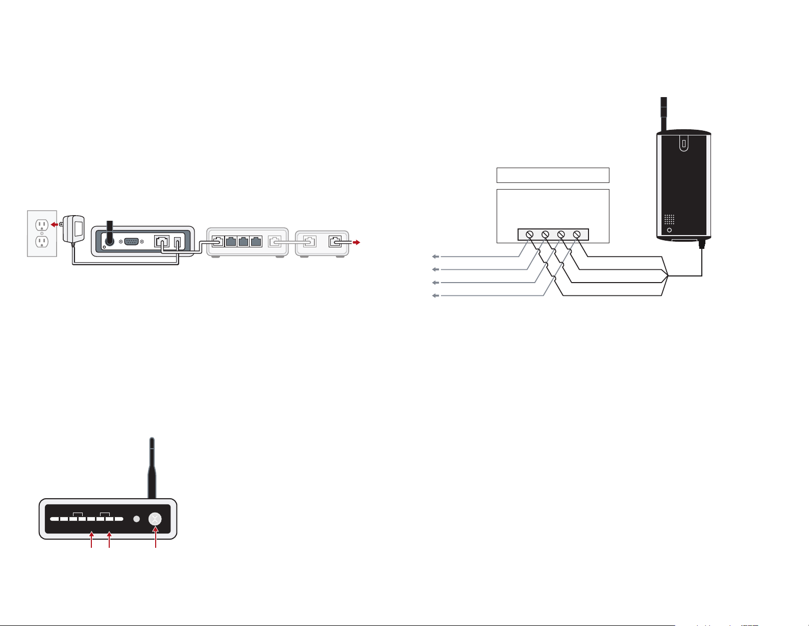
1. Locate the customer’s external internet connection and the in-home router. Find one unused
LAN RJ-45 port on the router. Then, use an Ethernet cable to connect the LAN RJ45 port on
the XG1000 Controller to the unused LAN RJ45 port on the router.
XG1OOO CONTROLLER
2
32 4
1
LAN LANWAN
ROUTER
(NOT INCLUDED)
DSL/CABLE MODEM
(NOT INCLUDED)
2. Connect XG1000 Controller to power and verify the following:
■
The XG1000 ‘X’ power LED is lighted BLUE
If the power LED is not lighted, please re-check all power connections
(see Troubleshooting Section)
■
The XG1000 LAN/Link LED is lighted GREEN
If the LAN/Link LED does not light check the Ethernet connection and/or
try using a different Ethernet cable (see Troubleshooting Section)
3. Wait up to 3 minutes for the XG1000 Controller to initialize.
4. Check and confirm LED marked ‘REM’ is solid GREEN (REM LED is the health indicator
for remote access).
INTERNET
1. Connect the Honeywell Bridge to the Honeywell Panel (or the keypad if possible)
The Bridge connects just like an additional keypad (SafeWatch Pro 3000 terminals noted).
Please power down the Honeywell Panel prior to beginning this process:
■ Black wire to Pin 4
■ Red wire to Pin 5
■ Green wire to Pin 6
HONEYWELL
BRIDGE
■ Yellow wire to Pin 7
SAFEWATCH PRO 3000
CONTROL TERMINAL STRIP
AUX.
AUX.
DATA
DATA
+
IN
OUT
5
6
7
BRIDGE YEL WIRE
BRIDGE GRN WIRE
BRIDGE RED WIRE
BRIDGE BLK WIRE
TO KEYPAD BLK WIRE
TO KEYPAD RED WIRE
TO KEYPAD GRN WIRE
TO KEYPAD YEL WIRE
–
4
NOTE: The existing keypad will remain connected. Mount the Bridge device near the alarm panel away
from large metal objects. If necessary, you can extend the length of the wire using four conductor cable
and wire nuts. For best results the bridge device should be mounted as high as possible, preferably at
least 6 feet above the floor.
2. Re-connect power to the Honeywell Panel.
3. The LED on the Honeywell Bridge should light up and display RED – If the LED does not light up,
the Bridge is not receiving power, please check all connections (see Troubleshooting Section).
If the LED changes from solid GREEN to solid RED within the first 60 seconds after applying power,
and remains solid RED, the Controller and the Bridge may be having difficulty communicating.
Please perform the Range Test described in the Troubleshooting Section of this manual.
ACT
DEV
STAT
LAN
REM
ACT
REMOTE
CONNECTIVITY
LINK
LAN LINK
POWER
INDICATOR
4. Go to existing alarm keypad. Disarm the alarm system, establish access to alarm system
via the “Installer Code” (may need to re-power unit and use ‘#*’ to set an installer code).
5. Connect a 6160 ALPHA KEYPAD if existing keypad is not alpha. From the keypad enable
the keypad address 22 in the alarm panel for use by the Honeywell Bridge (for the SafeWatch
Pro 3000, enter ‘[ 1, 0 ]’ in location ‘*195’).
I
2
Page 3

5. Log into your remote account via a PC browser. Click on the Account Settings tab on the
interface and then select the Discovery sub-tab, to access the Discovery page.
NOTE: If your XG1000 Controller is not registered to your account you
must register it prior to proceeding.
DEVICE DISCOVERY PAGE
On the Discovery page, click on the ‘START DISCOVERY’ button
to start the Bridge registration process. When the page heading
indicates that discovery is in process, press the ‘DISCOVERY’
DISCOVERY
BUTTON
button on the lower left corner of the Honeywell Bridge device
as shown.
COMPLETING THE INSTALLATION ///
1. Access your remote account via a PC browser and log in using your account UserID
and Password.
2. Click on the Device Overview tab to access the Device List for the system.
Once you are at the Device List, click on the Settings icon for the HoneywellAlarmPanel
to the right of the Device List.
DEVICE OVERVIEW PAGE
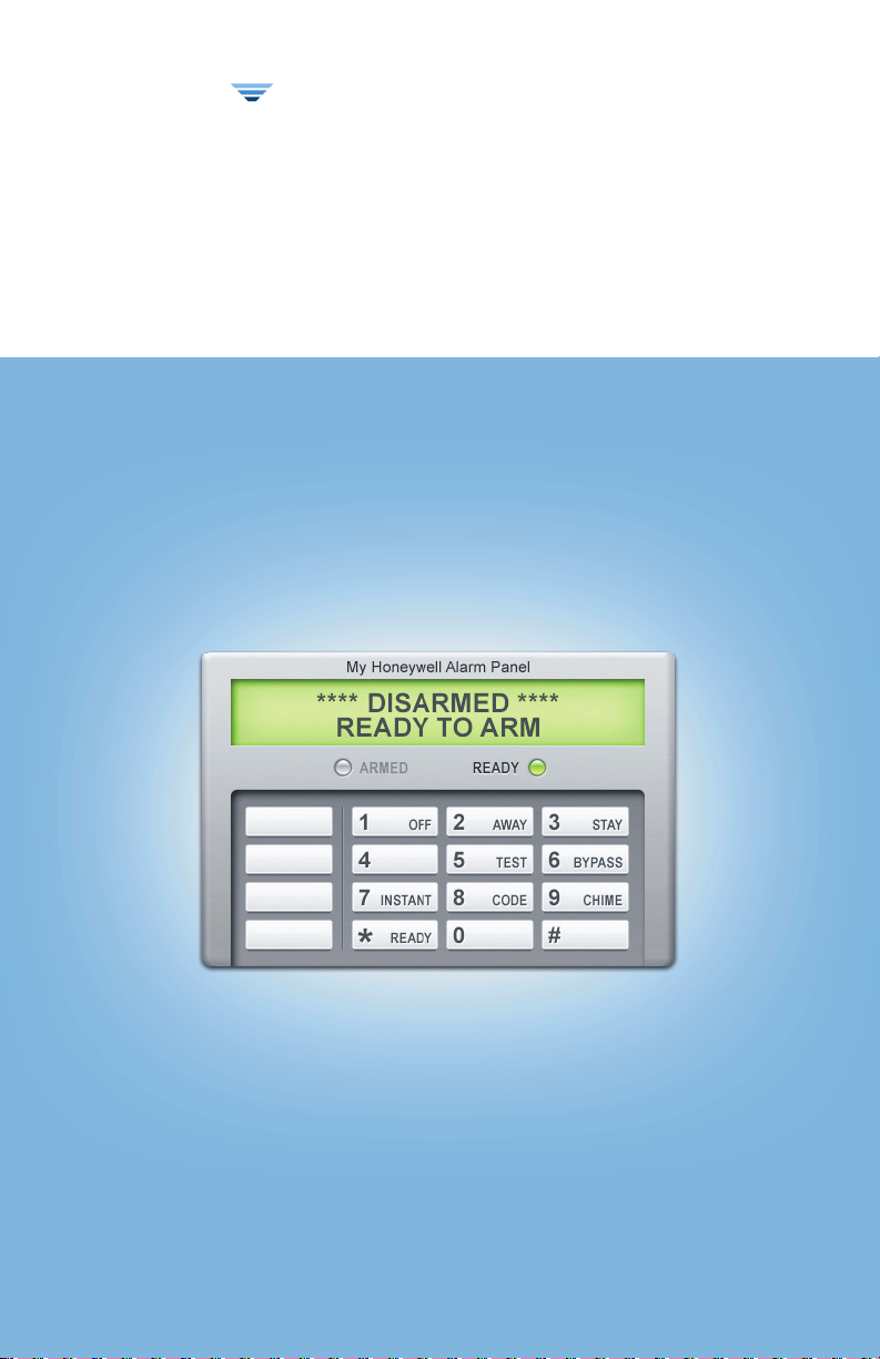
3. Send a test command through the Virtual Keypad to disarm the system and the status of
the panel will appear.
DEVICE DISCOVERY IN PROGRESS
When the Discovery process has finished for the Honeywell Bridge, it will appear on the list
of your devices on the Discovery page, and the LED on the Honeywell Bridge should turn GREEN.
At this point you may press the ‘STOP DISCOVERY’ button to stop the Discovery process.
HONEYWELL ALARM PANEL DISCOVERED
After the system has registered the Honeywell Bridge device, go to the Device Overview page and
verify that the Honeywell Bridge device was properly discovered.
3
4
Page 4

4. In the User Code field on the pop-up, the customer will enter a User Access Code for the
alarm system. Please note that this step is not required for manual operations.
This will enable the customer to set up Rules through the Security Wizard in their web account
(Until the customer completes this step, the XG1000 Controller will NOT be able to Arm/Disarm
the panel as part of a Rule/Schedule or through the quick ‘ARM/DISARM’ buttons at the top of
the Device List page).
NOTE: The user enters user code whenever they manually issue a command to arm/disarm from
their Virtual Keypad in their web account, just as they would if they were standing in front of their
keypad in their home.
5. Select the email/SMS addresses that you would like to receive Alarm Notifications
(if the address does not already appear in the list, click on the Add New button) and any
camera you would like to exclude from capturing video in the event of an Alarm Condition.
Click on the ‘APPLY CHANGES’ button to save your settings.
6. You must also go into programming and disable the Auto Stay function on the Alarm Panel –
otherwise if the alarm is set to Arm Away mode and the exit door is not opened the Alarm Panel
will automatically go to Arm Stay mode.
RANGE TEST
Perform this test if the LED indicator on the Honeywell Bridge continuously
shows solid RED and does not change to GREEN.
1. To test the range between the XG1000 Controller and
Honeywell Bridge you will need to quickly press and
release the ‘RANGE TEST’ button on the front panel of
the XG1000 Controller (see diagram). The left LED
DEV
LAN
ACT
STAT
REM
ACT
LINK
(next to the ACT LED) will turn GREEN when the test
has begun. (If the range test LED does not turn on, try
pressing the button one of two more times until it does,
wait at least 15 seconds between button presses).
Do NOT proceed until the range test LED has turned on
and is GREEN.
RANGE TEST INDICATOR
LAN LINK
RANGE TEST ON/OFF
2. Go to the Honeywell Bridge and view the LED on the front it
should be flashing ORANGE about once a second. If it is not flashing at all or is flashing very
slowly (i.e. once every five seconds) or if the LED is solid RED or GREEN, the range test is failing
and you will need to locate the Honeywell Bridge closer to the XG1000 Controller. You can do
this by extending the wire to the Bridge device, just like you would for a Honeywell Panel.
POWER INDICATOR
TROUBLESHOOTING ///
If you are having trouble operating this product, please consult the guide below:
PROBLEM
XG1000 Controller
‘X’ Blue power LED
does not light up
The XG1000
Controller
LAN/Link LED
is not Green
Honeywell Bridge
SOLUTION
1. Check that XG1000 is connected to power.
2. Check all power cables are firmly connected.
1. Check that the Ethernet cable connecting the XG1000 Controller to
the Router is firmly connected.
2. Try another Ethernet cable.
1. Check connections, the bridge is not receiving power.
LED does not
light up
The range test automatically shuts off after 5 minutes. To start the range test running again
push the ‘RANGE TEST’ button.
3. To finish the Range Test quickly press and release the ‘RANGE TEST’ button again on the front
panel of the XG1000 Controller. The range test LED will turn off. After the range test is complete
the LED on the Honeywell Bridge should be GREEN.
5
6
 Loading...