

Excel Smart I/O Compact
GENERAL
The Excel Smart I/O Compact is suitable for installation at
strategic locations throughout your buildings (see Table 1 for
an overview of versions).
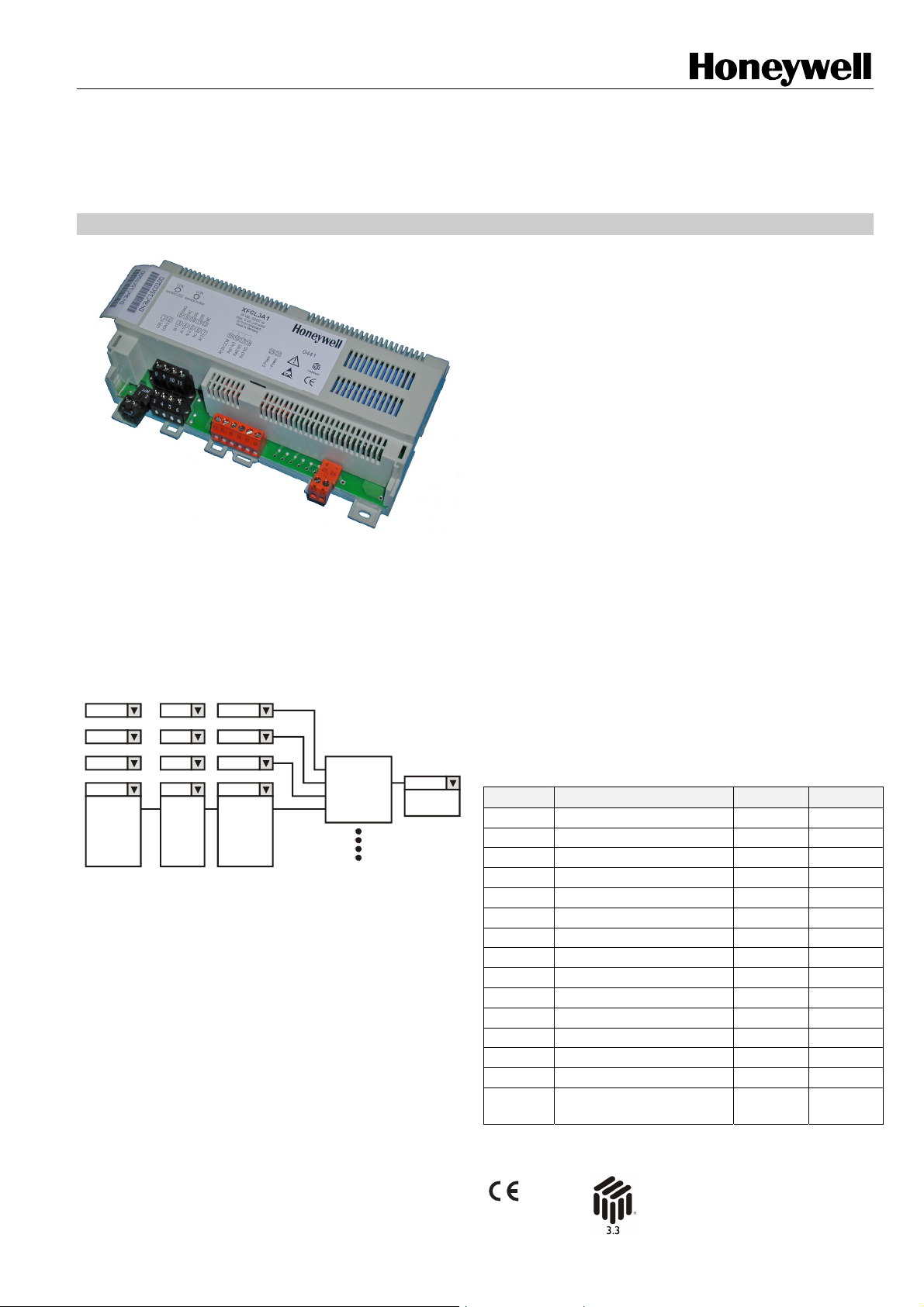
It features three digital inputs, three analog inputs, three relay
outputs, as well as an input/output functionality which
supports a switching logic functionality (see Fig. 1).
Input
DI1 1
AI2
nviDO1
DI2
DI3
AI1
AI2
AI3
DO2...
Condition
Fig. 1. Switching logic functionality
Example application 1: Monitoring of up to three springreturn damper actuators (no floating actuators)
A relay output can be used to open/close a damper, while the
inputs can be used to check if the end position has been
reached. This offers considerable time savings compared to
manual service. (This example application does not require
switching logic functionality.)
Application example 2: Switching a light via an
occupancy sensor or LONWORKS
An occupancy sensor can be used to switch ON/OFF a light
(with configurable hold-time) in e.g. a lavatory. This
application uses the switching logic functionality and runs
independently of the main CPU (e.g. XL500).
Comparison
=
>
=
ANDDI1 DI2
OR
>
<
=
>=
<=...
15
invalid
DI2
DI3
AI1
AI2
AI3
VAL UE. ..
&
Input
Relay1
Relay2
Relay3
XFCL2A1 AND XFCL3A1
PRODUCT DATA
FEATURES
• LONMARK™-compliant
• 2-wire
FT-X1 LONWORKS
with FTT10)
• Easily-accessible service button and service LED
• Flexible, configurable inputs/outputs:
- Three digital inputs configurable for static
pushbutton, pushbutton, or totalizing
- Three analog inputs configurable as NTC20k
sensor inputs or as slow digital inputs
- Three normally open contact relays
• Up to three different switching logic tables can run
simultaneously (independent of the main CPU – e.g.
XL500):
- Reduced LONWORKS communication
- Increased reliability
- Faster reaction
• DIN rail (wiring cabinet / fuse box) mounting and wall-
mounting supported
• 24 Vac (XFCL3A1) or 230 Vac (XFCL2A1) power
supply
• Optional terminal protection covers for wall mounting
• Optional swivel label holders for wiring information
(printed out via CARE)
• All module inputs and outputs are protected against
overvoltages of max. 40 Vdc and 24 Vac.
Table 1. Overview of Excel Smart I/O Compact versions
term. # function XFCL2A1 XFCL3A1
1, 2 removable LonWorks plug X X
3 digital input #1 X X
4 analog input #1 X X
5 analog input #2 X X
6, 7, 8, 9 GND for all signals X X
10 digital input #2 X X
11 digital input #3 X X
12 analog input #3 X X
13, 14 not used -- -15 common for relays 1, 2, 3 X X
16 relay #1 (N-O) X X
17 relay #2 (N-O) X X
18 relay #3 (N-O) X X
19 – 24 not used -- --
25, 26
removable power supply
plug
®
bus interface (compatible
230 Vac 24 Vac
® U.S. Registered Trademark
Copyright © 2008 Honeywell Inc. • All Rights Reserved EN0B-0487GE51 R0708
EXCEL SMART I/O COMPACT MODULES
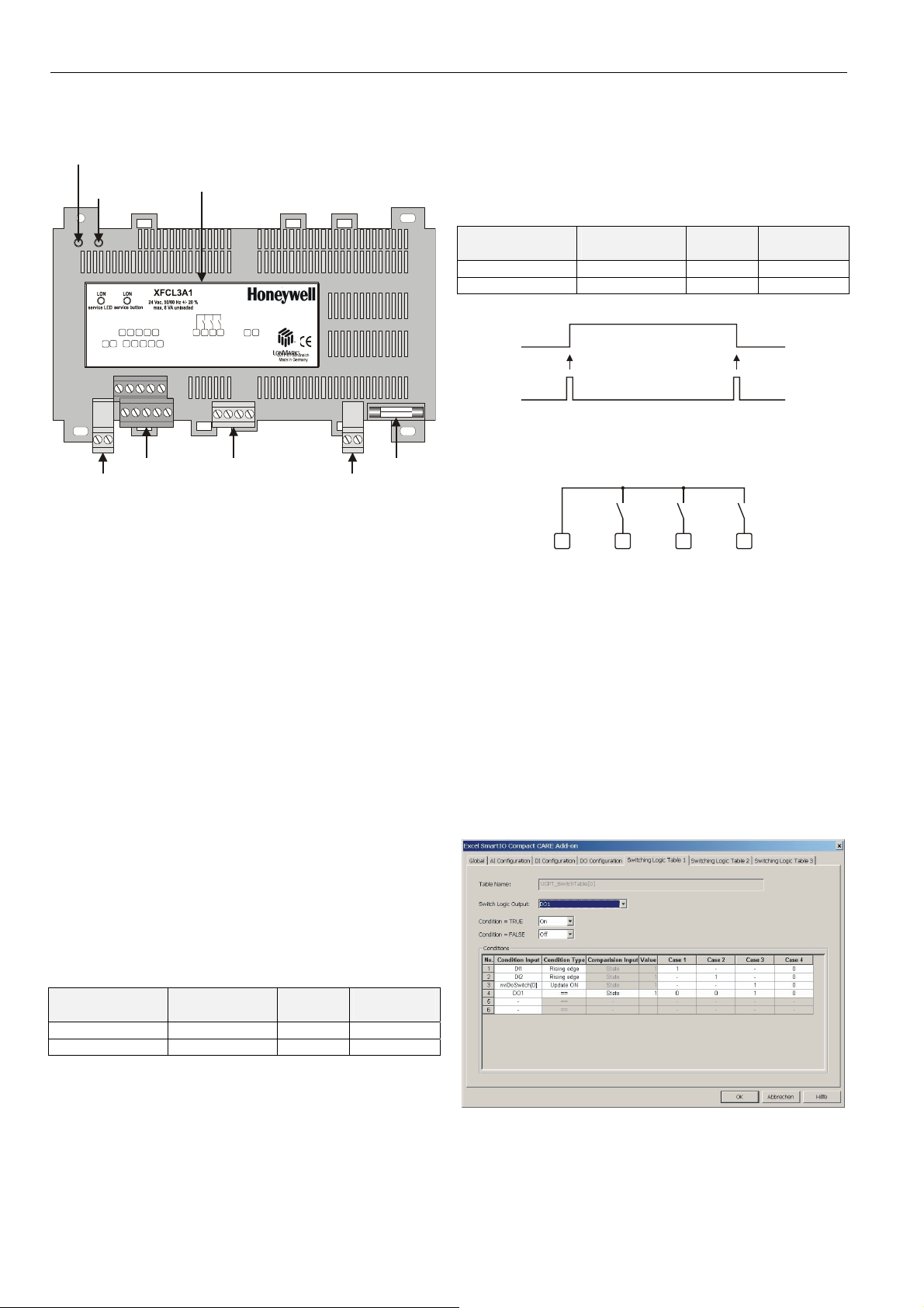
DESCRIPTION
LonWorks
service LED
LonWorks
service
button
LON 1
removable LonWorks
terminal plug
Fig. 2. Top view (optional terminal cover removed)
General
The Excel Smart I/O Compact is available in two versions with
different power supply voltage:
• XFCL2A1: 230 Vac [-15% / +10%], 50/60 Hz
• XFCL3A1: 24 Vac [±20%], 50/60 Hz
Both versions have three digital inputs, three analog inputs,
and three normally-open contact relays. Both versions are
equipped with a L
service LED.
The analog inputs of both versions have an individually
configurable offset. They have a 10-bit resolution, with a
typical accuracy of ±0.1 V and an impedance of > 100 kOhm
to GND for voltage input.
Both versions can be equipped with optional terminal
protection covers and swivel label holders (see section
"Accessories"). The Excel Smart I/O Compact has a
configurable receive / sent heart beat time (0…6553 s).
Analog Input Configuration Options
• NTC20k sensor input with optional sensor offset. The
threshold for the L
noise filter is selected by default.
• Slow DI with direct / reverse configuration option.
Table 2. Slow digital input characteristics
software detects
inputs as
closed < 5 kΩ < 1.5 Vdc < 0.3 mA
open > 50 kΩ > 3.5 Vdc < 0.1 mA
terminal assignment label
GND9GND
DI 2
DI 3
AI 3
12 15
8
10
11
3214 5 6
AI 1
DI 1
AI 2
LON 2
input terminals
GND
16
7
Rel 1 NO17Rel 2 NO18Rel 3 NO
GND
R123 COM
relay output terminals
ONWORKS service button and corresponding
ONWORKS update is configurable. A
resistive input
(dry contact)
0441
26
25
24V 0
24V ~
removable power
supply terminal plug
voltage
input
fuse
current out
of terminal
Digital Input Configuration Options
• Totalizer input; digital input 1 supports 20 Hz, digital inputs
1 and 2 support 5 Hz.
• Static digital input with direct / reverse configuration option
or pushbutton for flip-flop input.
Table 3. Digital input characteristics
software detects
inputs as
resistive input
(dry contact)
voltage
input
current out
of terminal
closed < 400 Ω < 0.8 Vdc max. 2.5 mA
open > 1.5 kΩ > 2.0 Vdc 0 … 1.5 mA
pushbutton flip-flop
digital input
Fig. 3. Pushbutton for flip-flop characteristics
Relay Outputs
15 16
common for
relays 1, 2, 3
17
relay 1 (N-O) relay 2 (N-O) relay 3 (N-O)
18
Fig. 4. Relay outputs
• Normally-open contacts with a common terminal for all
three relays (max. 3 A in total).
• Configurable start-up / communication failure state (e.g.
logical ON or OFF) in event of a communication failure.
• Configurable delay time and delay type (delayed ON,
delayed OFF, or delayed ON and OFF.
• Configurable switching level and hysteresis.
Example: Relay output is controlled by nviDoSwitch[1]
(SNVT_switch, 0…100%). Switching level is 20% and
hysteresis is 5%. The relay is switched ON at 20% and
OFF at 15%.
Switching Logic
EN0B-0487GE51 R0708
Fig. 5. Switching logic table
2

EXCEL SMART I/O COMPACT MODULES
• The switching logic functionality is configured using CARE
7.01.00 (or later).
• Excel Smart I/O Compact supports up to three switching
logic tables. Each logic table may have up to six condition
inputs and up to four condition cases.
• A condition input may be any of the inputs / outputs or the
respective input NV's.
• The output is switched if one of the condition columns is
TRUE. The relay output which will then be switched can
be selected. The switching logic has a higher priority than
a binding to the output.
• The following condition types may be selected: rising edge
for pulse input, falling edge for pulse input, >, >=, <, <=,
==, or !=.
• The comparison value may be a fixed value e.g. totalizer
value, an NV state e.g. invalid, an input NV, an input, or
an output.
Behavior in the Event of Sensor Break
In the event of a break in an NTC20k sensor, the conditions
"<", "<=", ">", and ">=" will be ignored.
If necessary, the break of an NTC20k sensor can be checked
using the condition "=invalid".
Excel Smart I/O Compact Response Times
Response Time for NV Update
The response time is defined as the interval between the
updating of the physical signal and the updating of the corresponding NV (or vice versa). Response times vary somewhat due to various factors. Assuming that only a single
digital input changes at any given time, the corresponding
response times is approx. 1.5 s. Thus, depending upon your
specific circumstances, the Excel Smart I/O Compact may be
suitable for rapid-response applications.
Response Time for Switching Logic
If you require a fast response time, you must use digital inputs
in a switching logic table. Analog inputs used as slow digital
input require a longer response time.
Typical response time for reaction to DI change:
• If only a single switching table is defined, the reaction time
to a digital input change is less than 0.5 s.
Typical response time for reaction to slow DI change:
• If only a single switching table is defined, the reaction time
to a slow digital input change is less than 1.5 s.
INTEROPERABILITY
The Excel Smart I/O Compact is compliant with LONMARK
Application Layer Guidelines V3.3.
LONWORKS Network Interface
The Excel Smart I/O Compact is equipped with a 10-MHz
3150 Neuron® chip. It communicates within the LonWorks
network at a rate of up to 78 kilo baud via an FT-X1 Free
Topology Twisted Pair Transceiver (compatible with FTT10A
transceivers).
Devices can be wired in daisy chain, star, or any combination
thereof as long as the max. wire length requirements are met.
The recommended configuration is a daisy chain with two
termination modules. This layout allows for max. bus length,
and its simple structure presents the least number of possible
problems, particularly when adding on to an existing bus. For
more information, refer to http://www.echelon.com
.
LONWORKS Service Button
All models feature a LONWORKS service button accessible
from the outside (see Fig. 2).
The service pin message is broadcast on the network
whenever the service button is pressed, but also after every
reset (due to power-up or software reset) and whenever the
mode is changed from offline to online.
LONWORKS Service LED
All models feature a LONWORKS service LED (see Fig. 2). For
more information on standard service LED behavior, refer to
the Excel Smart I/O Compact Installation Instructions
(EN1B0282-GE51).
Configuration and Binding
The switching logic functionality is configured using
Honeywell’s CARE 7.01.00 (or later) tool. The I/O functionality
can be configured using either CARE 7.01.00 (or later) or the
LNS plug-in. The LNS plug-in cannot be used to configure the
switching logic functionality.
NOTE: Do not use a browser for configuration as there is
then a high risk of incorrect configuration.
LONMARK Objects
The Excel Smart I/O Compact features:
• One Node Object (Obj#0);
• Three Open-Loop Sensor objects (Obj#1-3), one for each
physical universal input;
• Three Open-Loop Sensor objects (Obj#4-6), one for each
physical digital input;
• Three L
for each relay.
LONMARK Node Object
The LONMARK node object (see Fig. 6) allows the various
different objects in a node to be monitored. Upon receiving an
update to nviRequest, nvoStatus is updated. The definition of
SNVT_obj_request includes an object ID field to allow the
node object to report status conditions for all objects in a
node. The node self-documentation string lists the names of
the individual L
management node or tool to display useful information about
an Excel Smart I/O Compact; it also states (in the optional
part after the semicolon) that the node is an Excel Smart I/O
Compact, and lists its version number. The Excel Smart I/O
Compact has a configurable receive / sent heart beat time
(0…6553 s).
ONMARK open-loop actuator objects (Obj#7-9), one
ONMARK objects, allowing a network
EN0B-0487GE51 R0708
3

EXCEL SMART I/O COMPACT MODULES
nviRequest
SNVT_obj_request
nviDiagnRequest
UNVT_DiagRequest
SCPTmaxSendTime
SNVT_time_sec
SCPTmaxRcvTime
SNVT_time_sec
UCPT_SystSetting
UCPT_Version
Node Object
(LonMark Object type no. 0)
mandatory
1
#103
Network
Var iab le s
optional
Network
Variables
Configuration
Parameter
Value File
nvoStatus
SNVT_obj_status
nvoFileDirectory
SNVT_address
nvoHwType
UNVT_HWType
nvoHwIdentity
UNVT_HWIdentity
nvoDiagnostic
UNVT_Diagnostic
#101
#102
#104
Open-Loop Sensor Object
(LonMark Object type no. 1)
2
8
UCPT_DiType[x]
UCPT_DiProperties[x]
mandatory
Network
Var iab les
optional
Network
Var iab le s
Configuration
Parameter
Value File
nvoDiSwitch[x]
SNVT_switch
nvoDiCount[x]
SNVT_count
Fig. 8. Profile of L
ONMARK sensor objects for DIs
Open-Loop Sensor Object
(LonMark Object type no. 3)
nviDoSwitch[x]
SNVT_switch
UCPT_DOType[x]
mandatory
Network
Var iab les
optional
Network
Var iab le s
nvoDoActPosnFb[x]
SNVT_switch
UCPT_SwitchTable[3]
Fig. 6. Profile of LONMARK node object
LONMARK Sensor/Actuator Objects
Open-Loop Sensor Object
(LonMark Object type no. 1)
mandatory
Network
Var iab les
optional
Network
Var iab le s
UCPT_AIType[x]
UCPT_AISendOnDelta[x]
UCPT_AIProperties[x]
Fig. 7. Profile of L
Configuration
Parameter
Value File
ONMARK sensor objects for UIs
nvoAiTemp[x]
SNVT_temp_p
nvoAiSwitch[x]
SNVT_switch
UCPT_DOProperties[x]
UCPT_DOFailBehavior[x]
Configuration
Parameter
Value File
Fig. 9. Profile of LONMARK actuator objects for relays
The actuator is switched by the corresponding input NV (e.g.
nviDoSwitch[0]). There is one common receive heartbeat time
for all input NV's supporting a receive heartbeat. The receive
heartbeat time can be used for life check. A communication
failure behavior can be configured to define the desired action
in the event that an update of nviDoSwitch[] is missing within
the configured receive heartbeat time. All sensor objects have
an output NV showing the actual state of the physical output.
The output NV is updated whenever there is a change. There
is at least one update during the send heartbeat time. There
is just one common send heartbeat time.
EN0B-0487GE51 R0708
4

Table 4. Node Object network variables
NV name type description
nviRequest
SNVT_obj_request
nvoStatus
SNVT_obj_status
nvoFileDirectory SNVT_address
nvoHwType UNVT_HWType
nvoHWIdentify UNVT_HWIdentify
SCPTmaxSendTime SNVT_time_sec
SCPTmaxRcvTime SNVT_time_sec
UCPT_Version
RQ_NORMAL returns the object to enabled, non-overridden state.
RQ_DISABLED disables the object.
RQ_ENABLE enables the object.
RQ_UPDATE_STATUS posts the current settings of the flags of the specified object.
RQ_REPORT_MASK reports the supported flags of the specified object.
RQ_RESET resets the appropriate LONMARK object: If the digital input object is configured
for totalizing, it resets the totalizer to 65535 (0xFFFF); if associated to the node object, it
resets the node. Does not have an effect on other objects.
RQ_CLEAR_RESET requests that reset_complete be cleared.
All other requests read to an "invalid_request" error.
Object_id is the ID of the object within the node.
For invalid_id, a value of "1" means that the requested object ID is not implemented in this
node.
For invalid_request, a value of "1" means that unimplemented function has been
requested.
For disabled, a value of "1" means that the object has been disabled.
I/O objects not supported by the current hardware type are always disabled.
For open_circuit, a value of "1" means that an open circuit has been detected.
For out_of_service, a value of "1" means object not functional
For unable_to_measure, a value of "1" means that an I/O line has failed.
For comm_failure, a value of "1" means that network communications have failed.
One or more bound input NVs specified for receive heartbeat weren't updated within the
configured receive heartbeat time.
For report_mask, a value of "1" means that the status is an event mask.
For reset_complete, a value of "1" indicates the execution of the reset sequence. After a
reset sequence, the reset flag goes to TRUE (1) and remains in this state until it is cleared
(acknowledged).
Valid range: any value within user data memory of the Neuron Chip. The value points to a
file directory in the address space of the Neuron Chip. Used to access the configuration
properties accessed by network management read/write messages.
Set at factory. Represents the hardware type with respect to its OS number (e.g.
XFCL3A1). Typically, nvoHwType is polled for diagnostic purposes.
Set at factory. Used to identify the hardware by the number and types of I/Os supported by
the actual hardware type. This information is passed through the LONWORKS network as a
polled output NV. Typically, nvoHWIdentify is polled for diagnostic purposes.
Valid range: 0/10...6553 s (0 = no max. send time; 10…6553 = max. send time in
seconds); in increments of 1 s (default = 60.0 s). Defines the max. time before output NVs
are automatically updated (Send Heartbeat). It applies to those output NV's specified for
send heartbeat.
Valid range: 0/10...6553 s (0 = no max. send time; 10…6553 = max. send time in
seconds); in increments of 1 s (default = 0). Defines the max. time that elapses after the
last update to a bound input NV (Receive Heartbeat). Setting to zero disables the receive
failure detect mechanism. It applies to those input NV's specified for receive heartbeat. In
general, the receive heartbeat of the receiving device should be 3 times the send
heartbeat duration of the sending device or more.
Valid range set by application program. Identifies the current application and its version.
Passed through the L
ONWORKS network as a read-only file.
EXCEL SMART I/O COMPACT MODULES
EN0B-0487GE51 R0708
5

EXCEL SMART I/O COMPACT MODULES
Table 4. Continued
UCPT_SwitchTable
NV name type description
nvoAiTemp SNVT_temp_p
nvoAiSwitch SNVT_switch
UCPT_AIType not applicable Used to define the appropriate input type (0xFF: not used, 0: slow DI, 3: NTC20k).
UPCT_AISendDelta not applicable
UCPT_AIProperty not applicable
nvoDISwitch SNVT_switch
This configuration property is used to configure the switching logic.
SwitchLogicOutput:
Logical model output associated to the switching logic (OUTP_RELAY_1 (0x4),
OUTP_RELAY_2 (0x5), OUTP_RELAY_3 (0x6) or OUTP_NOT_USED (0xF))
IfResult:
Result if the condition is true (SWRES_OFF (0; 0%), SWRES_ON (1; 100%) or
SWRES_NUL (3; AUTO use nviDoSwitch))
ElseResult:
Result if the condition is not true (SWRES_OFF (0; 0%), SWRES_ON (1; 100%) or
SWRES_NUL (3; AUTO use nviDoSwitch))
SwitchTableRaw
ConditionInput
COND_INPUT_AI01 (0), COND_INPUT_AI02 (1), COND_INPUT_AI03 (2),
COND_INPUT_DI01 (4), COND_INPUT_DI02 (5), COND_INPUT_DI03 (6),
COND_INPUT_DO01 (8), COND_INPUT_DO02 (9), COND_INPUT_DO03 (10)
COND_INPUT_NVIDOSWITCH1 (12), COND_INPUT_NVIDOSWITCH2 (13),
ND_INPUT_NVIDOSWITCH3 (14), COND_INPUT_NotUsed (-1)
ConditionType
CONDITION_TYPE_EQUAL (0), CONDITION_TYPE_NOT_EQUAL (1),
CONDITION_TYPE_GREATER (2), CONDITION_TYPE_GREATER_EQUAL (3),
CONDITION_TYPE_LESS (4), CONDITION_TYPE_LESS_EQUAL (5)
ComparisionType
COMP_TYPE_AI01 (0), COMP_TYPE_AI02 (1), COMP_TYPE_AI03 (2),
COMP_TYPE_DI01 (4), COMP_TYPE_DI02 (5), COMP_TYPE_DI03 (6),
COMP_TYPE_DO01 (8), COMP_TYPE_DO02 (9), COMP_TYPE_DO03 (10),
COMP_TYPE_NVIDOSWITCH1 (12), COMP_TYPE_NVIDOSWITCH2 (13),
COMP_TYPE_NVIDOSWITCH3 (14),
COMP_TYPE_NotUsed (-1)
ComparisionValue
Temperature (-50 .. +150°C, INVALID), state (SW_ON (1), SW_OFF (0), SW_NUL (-1)),
totalizer (0..65535 counts)
Note:
DI or DO used with the condition type “>1” results in a rising edge detection.
DI or DO used with the condition type “<0” results in a falling edge detection.
Table 5. L
ONMARK sensor/actuator object NVs
Transmitted immediately when its value has changed by a rate higher than the configured "Send on Delta". Regularly transmitted as a heartbeat output. nvoAiTemp
represents the value measured by an AI configured as NTC20k sensor, otherwise it
shows invalid.
Transmitted immediately when its value has changed. Regularly transmitted as a heartbeat output. nvoAiSwitch represents the value measured by an AI configured as slow DI.
Defines the significant change rate of the associated input which should cause an
immediate NV update to be sent. Applies to the universal input type when configured for
"Temperature Sensor", and is ignored for other input types.
Used to define some properties associated to the analog input.
Noise Filter: 0: disabled, 1: enabled
INVALID for sensor break: 0: remain at last valid value after sensor break;
1: issue INVALID after sensor break;
Temperature Offset: -5.0 K to +5.0 K in steps of 0.1 K
Slow DI contact properties: 0: enabled on closed contact
1: disabled on closed contact
This variable is transmitted immediately when its value has changed. The value is
regularly transmitted as a heartbeat output. nvoDISwitch represents the value measured
by a DI configured as fast DI.
state value
Enabled: 1 100%
Disabled: 0 0%
not configured or object is disabled: -1 n.a.
EN0B-0487GE51 R0708
6

EXCEL SMART I/O COMPACT MODULES
Table 5. Continued
nvoDICount represents the value measured by a DI configured as totalizer. The valid
range for the totalizer count is 1... 65534. The value 0xFFFF=65535 is used to indicate a
nvoDICount SNVT_count
UCPT_DIType not applicable
UCPT_DIProperty not applicable
nvoDoActPosnFb SNVT_switch
nviDoSwitch SNVT_switch
UCPT_DOType not applicable Used to define the appropriate digital output type (0xFF: not used, 0: ON/OFF actuator).
UCPT_DOProperty not applicable
UCPT_DOFailBehav not applicable
reset to the totalizer. The value is transmitted immediately when its value has changed
more counts than defined in "Send on Delta". Regularly transmitted as a heartbeat
output. After power-up and reset, the value 0xFFFF=65535 is sent to the network to
indicate to the receiving device that previous count values have been lost due to a reset.
Used to define the appropriate digital input type (0xFF: not used, 0: fast digital input, 1:
totalizer input).
Used to define the properties associated with a digital input.
Fast digital input: 0: enabled on closed contact
1: disabled on closed contact
Pushbutton Setup: 0: no pushbutton;
2: pushbutton for flip/flop;
Default after power-up /
communication failure for
flip-flop configuration: 0: disabled / 0%;
1: enabled / 50%;
2: enabled / 100%;
3: INVALID;
Trigger edge: 0: count on positive edge;
1: count on negative edge;
Send on delta: specifies what difference in totalizer counts is required
before a transmission of the value output takes place,
0..255 count; resolution 1 count;
Represents the current status of the relay.
state value
Output position (ON): 1 100%
Output position OFF: 0 0%
not configured: -1 0xFF
This variable is transmitted immediately when the corresponding network input variable
has changed. nvoDoSwitch does not support the send heartbeat time.
Used to drive the relay.
state value
OFF: 0 n.a.
OFF: 1 0
switched according to configuration: 1 0.5…100%
Invalid: 1 n.a.
This value is adopted at power-up and in case an update is not received within the
specified receive heartbeat time.
Used to define the properties associated with a digital output.
Direct reverse: 0: direct operation
1: reverse operation
Output delay type: 0: no delay
1: ON delay
2: OFF delay
3: ON-OFF delay
On level: switch ON level in %, e.g. 20%
Hysteresis: hysteresis, e.g. switch ON at 20% and OFF at 15%, if
hysteresis is 5%.
Output delay time: 1…240 s in steps of 1 s (or 1…240 min in steps of 1 min)
This configuration property is used to set-up the default behavior in case of a missing
network input update for the appropriate digital output.
Failure behavior: 0: OFF
1: reserved
2: ON
3: remain in current position
EN0B-0487GE51 R0708
7

EXCEL SMART I/O COMPACT MODULES
Accessories, Standards, Ratings, and
Literature
Accessories
• Swivel label holders; order number: XAL_LAB_L
• 209541B Termination Module (one or two required,
depending on L
Installation Instructions, EN1R-1047GE51 for details).
• Terminal protection covers; order number: XAL_COV_L
Approvals and Standards
• CE and EN 50081-1
• L
ONMARK Application Layer Guidelines Version 3.3
Housings
• IP30 with protection covers or IP20 without protection
covers.
Environmental Ratings
• Operating temperature: +32...+122 °F (0...+50 °C)
• Shipping/storage temperature: -22...+158 °F (-30...+70 °C)
• Relative humidity (operation and storage): 5...90%, non-
condensing
ONWORKS bus layout; see Excel 500
Applicable Literature
• Excel Smart I/O Compact Installation Instructions (EN1B0282-GE51)
• Excel 50/500 L
• Excel 10 FTT/LPT 209541B Termination Module
Installation Instructions, form 95-7554
• Honeywell's Excel Smart IO / Excel 12 plug-in help file
ONWORKS Mechanisms (EN0B-0270GE51)
DIMENSIONS
All models have the same dimensions (W x L x H =
110 x 180 x 60 mm) (see Fig. 10).
59.5
terminal protection
90
110
130
Fig. 10. Excel Smart I/O Compact (dimensions in mm)
cover (optional)
Manufactured for and on behalf of the Environmental and Combustion Controls Division of Honeywell Technologies Sàrl, Ecublens, Route du Bois 37, Switzerland by its Authorized Representative:
Automation and Control Solutions
Honeywell GmbH
Böblinger Strasse 17
71101 Schönaich / Germany
Phone: (49) 7031 63701
Fax: (49) 7031 637493
http://ecc.emea.honeywell.com
Subject to change without notice. Printed in Germany
EN0B-0487GE51 R0708
 Loading...