


Excel Smart I/O
XFC1Axx, XFC1Dxx, XFC2Axx,
XFC2Dxx, XFC3Axx, AND XFC3Dxx MODULES
PRODUCT DATA
FEATURES
• LONMARK™ association-compliant, thus suitable for all
open L
ONWORKS
• Flexible, software-configurable inputs/outputs
• Flash memory for downloading applications (thus
increasing flexibility and facilitating future upgrading)
• 2-wire FTT-10A L
• Easily-accessible service button and a service LED
• Four fast digital inputs configurable for static input or
totalizing (at up to 20 Hz)
• Four relays to which (after software-configuration) e.g.
floating actuators can be directly connected
• Two or (model-dependent) four universal inputs, each
with extra terminal for powering 24 Vac sensors, supporting (model-dependent) different sensor types, also
configurable for voltage-variable or slow digital input
• Two analog outputs, each with extra terminal for
powering 24 Vac actuators, supporting (modeldependent) voltage-variable or current-variable output
• Greater reliability, fewer cables (thus reducing fire
burden), lower installation costs, easy start-up and
servicing, digital communication
• DIN rail (wiring cabinet / fuse box) mounting and wall-
mounting supported
• Easy wiring check using the XILON Handheld MMI
• Fixed or removable terminals (model-dependent)
• 24 Vac, 110 Vac, or 230 Vac power supply (model-
dependent)
• Optional six three-position, software-configurable
manual overrides and corresponding feedback
• Optional terminal protection covers for wall mounting
• Optional swivel label holders for wiring information
®
networks
ONWORKS
®
bus interface
GENERAL
Excel Smart I/O modules are LONMARK association-compliant
devices, and can thus be used in all open L
ments. They feature a variety of software-configurable digital
and analog inputs and outputs and are suitable for installation
at strategic locations throughout your buildings. The modules
convert physical input signals from sensors into network
variables and the network variables into physical output
signals for operating actuators.
The diverse mix of inputs and outputs (flexibly configurable
using Honeywell's LonMaker for Windows™ plug-in) makes
the Excel Smart I/O ideally suited for a wide range of
intelligent, distributed applications.
Table 1 provides a brief overview of the available versions.
See Table 4 on page 10 for details.
® U.S. Registered Trademark
Copyright © 2008 Honeywell Inc. • All Rights Reserved EN0B-0311GE51 R0708
ONWORKS environ-
Table 1. Brief Overview of Excel Smart I/O Versions
Version
XFC1A06001 110 Vac no 4 4 2 4
XFC1D06001 110 Vac yes 4 4 2 4
XFC2A05001 230 Vac no 2 4 2 4
XFC2A06001 230 Vac no 4 4 2 4
XFC3A04001 24 Vac no 4 4 2 4
XFC3A05001 24 Vac no 2 4 2 4
XFC3A06001 24 Vac no 4 4 2 4
XFC2D05001 230 Vac yes 2 4 2 4
XFC2D06001 230 Vac yes 4 4 2 4
XFC3D04001 24 Vac yes 4 4 2 4
XFC3D05001 24 Vac yes 2 4 2 4
XFC3D06001 24 Vac yes 4 4 2 4
power overrides UIs DIs AOs relays
Description
EXCEL SMART I/O MODULES
DESCRIPTION
With the Excel Smart I/O, you can choose from among ten
variants featuring different assortments of universal inputs,
digital inputs, analog outputs, and relays for use in conjunction with a wide range of sensor types and actuators. All
module inputs and outputs are protected against overvoltages
of max. 40 Vdc and 24 Vac. An extra power output terminal
accompanying each analog input/output can also be used to
power 24 Vac field devices.
Further, the individual inputs and outputs can be flexibly configured using Honeywell's LonMaker for Windows software
plug-in. Thus, each of the four fast digital inputs can be configured for static input from dry contacts or open collectors or
for totalizing signals having a frequency of up to 20 Hz, while
the universal inputs can be configured for analog signals from
specific sensor types (model-dependent), or for voltagevariable input, or for slow digital input (max. frequency =
0.25 Hz).
The XFC1D06, XFC2D05 and XFC2D06 as well as the
XFC3D04, XFC3D05, and XFC3D06 are equipped with six 3position manual override switches. Using Honeywell's software plug-in, these switches can be configured to override the
individual relays or analog outputs. These modules also
feature ten status LEDs showing the condition of the inputs /
outputs allocated to them.
The XFC2A05, XFC2A06, XFC2D05, and XFC2D06 (long
housing) are equipped with a transformer enabling them to be
powered with 230 Vac (+10%/-15%). The XFC1A06 and
XFC1D06 (long housing) have a transformer enabling them to
be powered with 110 Vac (+10%/-15%). For both the 230 Vac
and 110 Vac models, the standby power consumption (= all
outputs are inactive, all inputs are open, and all LEDs –
except the power LED – are OFF) is less than 10 VA. All
other models (short housings) require 24 Vac (±20%); their
standby power consumption is less than 5 VA.
All modules are equipped with a power LED as well as with a
L
ONWORKS service button and corresponding service LED.
Matching terminal protection covers and swivel label holders
are available for all modules.
• four LONMARK open-loop sensor objects (Obj#1-4) (one for
each universal input),
• four L
ONMARK open-loop sensor objects (Obj#5-8) (one for
each digital input),
• two L
ONMARK open-loop actuator objects (Obj#9-10) (one
for each analog output), and
• four L
ONMARK open-loop actuator objects (Obj#11-14) (one
for each relay).
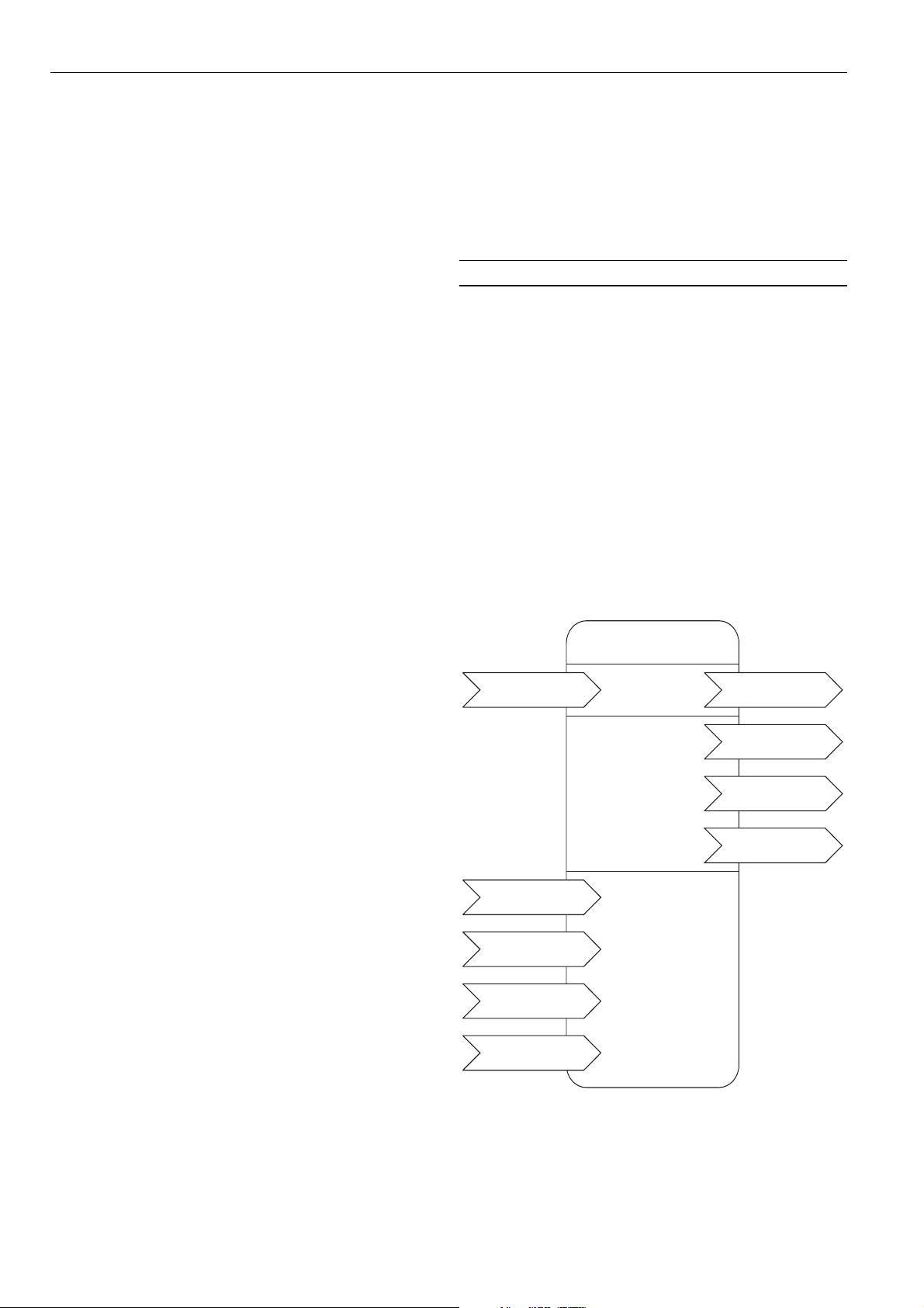
LONMARK Node Object
The LONMARK node object allows the various different objects
in a node to be monitored. Upon receiving an update to
nviRequest, nvoStatus is updated. The definition of
SNVT_obj_request includes an object ID field to allow the
node object to report status conditions for all objects in a
node. The node self-documentation string lists the names of
the individual L
ment node or tool to display useful information about an Excel
Smart I/O; it also states (in the optional part after the
semicolon) that the node is an Excel Smart I/O, and lists its
version number.
Example:
network input sd_string("@x|y") SNVT_xxx
nvName;
where input can be replaced by output, x refers to the
object x listed within set_node_sd_string, and y is the NV
index within the following L
set_node_sd_string
"&"&3.2@0,1[4AI,1[4DI,3[2AO,3[4DO;SmartIO_01"
SNVT_obj_request
ONMARK objects, allowing a network manage-
ONMARK object definition:
Node Object
(LonMark object type no. 0)
nviRequest
mandatory
Network
Variables
nvoStatus
SNVT_obj_status
nvoFileDirectory
SNVT_address
INTEROPERABILITY
The Excel Smart I/O is compliant with LONMARK Application
Layer Guidelines V3.2. and thus interoperable with all other
devices in open L
devices). See also section "LonWorks Network Interface."
Excel Smart I/O Module Response Times
The response time is defined as the interval between the
updating of the physical signal and the updating of the
corresponding NV (or vice versa). Response times vary
somewhat due to various factors. Assuming that only a single
digital input changes at any given time, the corresponding
response times will typically amount to approx. 1 sec. Thus,
depending upon your specific circumstances, the Excel Smart
I/O may be suitable for rapid-response applications.
LONMARK Objects
The Excel Smart I/O features a total of 15 LONMARK objects:
• one LONMARK node object (Obj#0) to allow monitoring and
setting the status of the various sensor / actuator objects,
EN0B-0311GE51 R0708 2
ONWORKS networks (including third-party
SCPTmaxSendTime
SNVT_time_sec
SCPTmaxRcvTime
SNVT_time_sec
UCPT_Poll
UCPT_Version
Fig. 1. Profile of L
optional
Network
Variables
optional
configuration
properties
ONMARK Node Object
nvoHwType
UNVT_HWType
nvoHwIdentify
UNVT_HWIdentify

NV Name Type Description
nviRequest
SNVT_obj_request
nvoStatus
SNVT_obj_status
nvoFileDirectory SNVT_address
nvoHwType UNVT_HWType
nvoHWIdentify UNVT_HWIdentify
SCPTmaxSendTime SNVT_time_sec
SCPTmaxRcvTime SNVT_time_sec
UCPT_Poll
UCPT_Version
EXCEL SMART I/O MODULES
Table 2. Node Object network variables
RQ_NORMAL returns the object to the enabled, non-overridden state.
RQ_DISABLED disables the object.
RQ_ENABLE enables the object.
RQ_UPDATE_STATUS posts the current settings of the flags of the specified object.
RQ_REPORT_MASK reports the supported flags of the specified object.
RQ_RESET resets the appropriate LONMARK object: If the digital input object is configured
for totalizing, it resets the totalizer to 65535 (0xFFFF); if associated to the node object, it
resets the node.
RQ_CLEAR_RESET requests that reset_complete be cleared.
All other requests read to an "invalid_request" error.
object_id is the ID of the object within the node.
For invalid_id, a value of "1" means that the requested object ID is not implemented in this
node.
For invalid_request, a value of "1" means that unimplemented function has been
requested.
For disabled, a value of "1" means that the object has been disabled: those I/O objects not
supported by the current hardware type will always be disabled.
For open_circuit, a value of "1" means that an open circuit has been detected.
For unable_to_measure, a value of "1" means that an I/O line has failed.
For comm_failure, a value of "1" means that network communications have failed: one or
more bound input NVs specified for receive heartbeat weren't updated within the
configured receive heartbeat time.
For manual_control, a value of "1" means that the actuator is under local control: this field
applies to the output objects and the node object, only, and notifies whether the
appropriate output was manually overridden.
Not supported.
For in_override, a value of "1" means that the module has been overridden via
nviAoManOvrd or nviDoManOvrd (e.g. using the XILON Handheld MMI)
For report_mask, a value of "1" means that the status is an event mask.
Not supported.
For reset_complete, a value of "1" indicates the execution of the reset sequence. After a
reset sequence, the reset flag goes to TRUE (1) and remains in this state until it is cleared
(acknowledged).
Valid range: Any value within user data memory of Neuron Chip. Points to a file directory
in the address space of the Neuron Chip. Used to access the configuration properties
accessed by network management read/write messages.
Set at factory; stored in coprocessor's EEPROM. Represents the hardware type with
respect to its OS number (e.g. XFC3A014001) and the coprocessor's software version.
The hardware type is passed through the L
Typically polled for diagnostic purposes.
Set at factory; stored in coprocessor's EEPROM. Used to identify the hardware by the
number and types of I/Os supported by the actual hardware type. This information is
passed through the L
ONWORKS network as a polled output NV. Typically polled for
diagnostic purposes.
Valid range: 10...6553 s; in increments of 1 s (default = 60.0 s). Defines the maximum
period of time before output NVs are automatically updated. Defines the Maximum Send
Time and is accessible using standard L
Valid range: 0...6553 s (default = 0). Defines the max. time that elapses after the last
update to a bound input NV. Defines the Maximum Received Time and is accessible
using standard L
ONMARK mechanisms. Setting to zero disables the receive failure detect
mechanism.
Valid range: Pre-set at factory. Configures the start-up behavior for input NVs with respect
to getting an immediate update through a poll request. If enabled, any input NV bound to
another node will initiate a poll request after reset, thus helping to avoid start-up problems
until the next NV update. Polling based on a time grid of 1 sec, only. If disabled, the input
NVs remain invalid until the next update is sent.
Valid range: Pre-set by application program. Identifies the current application and its
version. Passed through the L
standard L
ONMARK mechanisms.
ONWORKS network as a read-only file. Readable using
ONWORKS network as a polled output NV.
ONMARK mechanisms.
3 EN0B-0311GE51 R0708

EXCEL SMART I/O MODULES
LONMARK Sensor/Actuator Objects
All actuator objects have an output NV showing the actual
state of the physical output and whether it is in the automatic
or manual override mode. All sensor objects have a common
configuration property defining the heartbeat time.
LONMARK Open-Loop Sensor Objects for Universal Inputs
The Excel Smart I/O makes use of four LONMARK open-loop
sensor objects (one for each universal input) suitable for use
in applications in which the actuator provides no feedback.
LONMARK Open-Loop Actuator Objects for Analog Outputs
The Excel Smart I/O makes use of two LONMARK open-loop
actuator objects (one for each analog output).
Open-Loop Actuator Object
(LonMark object type no. 3)
mandatory
Network
Var iab les
optional
Network
Var ia ble s
SCPTdirection[x]
SNVT_state
UCPT_AOType[x]
optional
configuration
properties
Fig. 2. Profile of LONMARK sensor object for UIs
LONMARK Open-Loop Sensor Objects for Digital Inputs
The Excel Smart I/O makes use of four LONMARK open-loop
sensor objects (one for each digital input).
Fig. 4. Profile of L
ONMARK actuator objects for AOs
LONMARK Open-Loop Actuator Objects for Relays
The Excel Smart I/O makes use of four LONMARK open-loop
actuator objects (one for each relay) individually configurable
as simple ON/OFF controls or as floating outputs (in order to
drive two physical outputs with configurable runtimes).
Fig. 3. Profile of L
EN0B-0311GE51 R0708 4
ONMARK sensor objects for DIs
Figure 5. Profile of L
ONMARK actuator objects for relays

EXCEL SMART I/O MODULES
Table 3. LONMARK sensor/actuator object NVs
NV Name Type Description
nvoAiValuePct SNVT_lev_percent Transmitted immediately when its value has changed by a rate higher than the con-
figured "Send on Delta". Regularly transmitted as a heartbeat output.
nvoAiTemp SNVT_temp_p
nvoAiSwitch SNVT_switch Transmitted immediately when its value has changed. Regularly transmitted as a
UCPT_AIType not applicable Used to define the appropriate input type. Stored in the configuration parameter file
UPCT_AISendDelta not applicable Defines the significant change rate of the associated input which should cause an
UCPT_AIProperty not applicable Used to define some properties associated to the analog input. Stored in the con-
nvoDISwitch SNVT_switch Represents a slow digital input connected to the digital input terminals. According to its
nvoDICount SNVT_count Transmitted immediately when its value has changed more counts than defined in
nvoDiOccupancy SNVT_occupancy Transmitted immediately when the digital input state has changed. Regularly transmitted
UCPT_DIType not applicable Used to set up the type of DI. It is stored in the configuration parameter file accessible
UCPT_DIProperty not applicable Used to define the properties associated with a digital input.
nvoAoActPosnFb SNVT_switch Represents the current status of the analog output, including feedback related to
nviAoSwitch SNVT_switch Used to drive the analog output to 0...100%. Typically bound to a LONWORKS control
nviAoValuePct SNVT_lev_percent Used to drive the AO to 0...100%. Typically bound to a LONWORKS control device
nviAoManOvrd SNVT_switch Used to manually override the analog output to 0...100%. Has priority over nviAoSwitch
SCPTdirection SNVT_state Used to set the actuator sense of rotation and the safety position in case of any failure.
UCPT_AOType not applicable Used to set up the various properties associated with an analog output point. Stored in
Transmitted immediately when its value has changed by a rate higher than the configured "Send on Delta". Regularly transmitted as a heartbeat output.
heartbeat output.
accessible using standard LonMark mechanisms. Used by the NEC coprocessor.
immediate NV update to be sent. Stored in the configuration parameter file accessible
using standard L
ONMARK mechanisms. Applies to the universal input type when con-
figured for "Voltage" or "Temperature Sensor", respectively, and will be ignored for other
input types.
figuration parameter file accessible using standard L
ONMARK mechanisms. Used by the
NEC coprocessor.
configuration with respect to a normally open / normally closed contact, the output NV
shows "state=0 / value=0%" for the "disabled" logical state, and "state=1 / value=100%"
for the "enabled" logical state. Regularly transmitted as a heartbeat output as dictated
by nciSndHrtBt.
"Send on Delta". Regularly transmitted as a heartbeat output. After power-up and reset,
the value 0xFFFF=65535 will be sent to the network to indicate to the receiving device
that previous count values have been lost due to a reset.
as a heartbeat output as dictated by nciSndHrtBt.
using standard L
ONMARK mechanisms.
manual override initiated from either nviAoManOvrd or the manual override switches.
Typically used for monitoring purposes at supervisory stations or for diagnostic
purposes. In the case of an override, the state is equal to -1.
device issuing an output level 0...100%. A value of 110% is also possible
(corresponding to a voltage range of 0...11 V).
issuing an output level 0...100%. A value of 110% is also possible (corresponding to a
voltage range of 0...11 V).
and nviAoValuePct. Typically used during start-up and commissioning, supported by the
XILON Handheld MMI, and does not have to be bound. If the relay is at present
manually overridden, this will be reflected in nvoAoActPosnFb, accordingly. The manual
override remains in force until explicitly reset to normal operation via power-up and
reset. This state is therefore stored in EEPROM. If there has been a manual override to
the same output, this will have priority over nviAoManOvrd.
Stored in the configuration parameter file accessible using standard L
ONMARK
mechanisms.
the configuration parameter file accessible using standard L
ONMARK mechanisms.
5 EN0B-0311GE51 R0708

EXCEL SMART I/O MODULES
nvoDoActPosnFb SNVT_switch Represents the current status of the relay, including feedback related to manual over-
ride initiated from either nviDoManOvrd or the manual override switches. Typically used
for monitoring purposes at a supervisory station or for diagnostic purposes. In the case
of floating actuator, nvoDoActPosnFb will monitor the actual valve position based on the
calculation of the position within the motor model. In the case of an override, the state is
equal to -1.
nviDoSwitch SNVT_switch Used to drive the relay, which can be configured for different models, such as simple
ON/OFF output, or floating output. Typically bound to a L
issuing an output level ON/OFF or 0...100%, as the case may be.
nviDoValuePct SNVT_lev_percent
nviDoManOvrd SNVT_switch
UCPT_DOType not applicable Used to set-up the type of the relay point. Stored in the configuration parameter file
UCPT_DOProperty not applicable Used to set-up the various properties of a relay. Depending upon the selected output
UCPT_StatusLED not applicable Used to set-up the various properties associated with a status LEDs. Stored in the con-
UCPT_ManOvrdSw not applicable Used to set-up the manual override switches accordingly. Stored in the configuration
Used to drive the relay to 0…100% when configured for floating type. Typically bound to
ONWORKS control device issuing an output level 0…100%. If both nviDoSwitch and
a L
nviDoValuePct receive valid values, nviDoValuePct will have priority.
Used to manually override the relay to ON/OFF. Has priority over nviDoSwitch and
nviDoValuePct. Typically used during start-up and commissioning, supported by the
XILON Handheld MMI, and does not have to be bound. If the relay is at present
manually overridden, this will be reflected in nvoDoActPosnFb, accordingly. The manual
override remains in force until explicitly reset to normal operation via power-up and
reset. This state is therefore stored in EEPROM. If there has been a manual override to
the same output, this will have priority over nviDoManOvrd.
accessible using standard L
type, various different properties can be set-up which are stored in the configuration
parameter file accessible using standard L
coprocessor.
figuration parameter file accessible using standard L
NEC coprocessor.
parameter file accessible using standard L
coprocessor.
ONMARK mechanisms. Used by the NEC coprocessor.
ONMARK mechanisms. Used by the NEC
ONMARK mechanisms. Used by the NEC
ONWORKS control device
ONMARK mechanisms. Used by the
TECHNICAL DATA
General
The Excel Smart I/O is equipped with a 10-MHz 3150
Neuron® Chip (which executes the application program and
implements the LonTalk protocol) and a NEC coprocessor
(for handling the inputs and outputs). It communicates within
the L
ONWORKS network at a rate of 78 kilobaud via an FTT-
10A Free Topology Twisted Pair Transceiver
Each module is equipped with four 230 Vac, 6 A digital
outputs, i.e. relays (including two normally open [N.O.] and
two changeover [C.O.] relays). Floating actuators can be
directly connected to these relays once they have been
configured using Honeywell's LonMaker for Windows plug-in.
Further, each Excel Smart I/O is equipped with four fast digital
inputs. Each fast digital input can be reconfigured (using the
Honeywell plug-in) to accept static input (from dry contacts or
open collectors) or to totalize input signals (having a
frequency of up to 20 Hz).
Depending upon the given model, each module is also
equipped with a varying number of different universal inputs
and analog outputs (see section "Universal Inputs and Analog
Outputs" below), each of which has an extra power output
terminal for supplying 24 Vac power to field devices.
Certain models also feature six 3-position manual override
switches and ten status LEDs (see section "Manual Overrides
and Status LEDs" below).
Optional accessories include swivel label holders and terminal
protection covers (see "Optional Accessories" below).
A power LED, a L
ponding L
ONWORKS service button (see sections "LONWORKS
Service LED" and "L
ONWORKS service LED, and a corres-
ONWORKS Service Button" below) are
located on the top of each module.
There are two standard module sizes: the long module (with a
built-in 230 Vac transformer) and the short module (which
requires 24 Vac power). See section "Long and Short
Housings" below.
Universal Inputs and Analog Outputs
Further, depending upon the given model, the modules are
equipped with a variable number of different universal inputs
and analog outputs.
Universal Inputs
The term "universal inputs" refers to analog inputs for
temperature-sensor signals which can also be reconfigured
(using the Honeywell plug-in) as voltage-variable or slow
digital inputs (e.g. for dry-contact/open-collector signals).
Each module is equipped with universal inputs of one of the
following three types:
EN0B-0311GE51 R0708 6

EXCEL SMART I/O MODULES
• The first type can be configured for analog signals from
NTC20k sensors or for 0...10 Vdc/2..10 Vdc voltage
signals or for slow digital input (max. frequency = 0.25 Hz).
• The second type can be configured for analog signals from
three-wire PT100 sensors or for 0...10 Vdc/2..10 Vdc
voltage signals or for slow digital input (max. frequency =
0.25 Hz). The XFC3A04001 and XFC3D04001 are
equipped with two universal inputs of this type, the
reconfiguration of which yields four voltage-variable or slow
digital inputs.
• The third type can be configured for analog signals from
PT1000, Ni1000, and Ni1000TK5000 sensors or for
0...10 Vdc/2..10 Vdc voltage signals or for slow digital input
(max. frequency = 0.25 Hz).
The universal inputs of all models have an individually
configurable offset.
The universal inputs of the XFC3A06001, XFC3D06001,
XFC2A06001, and XFC2D06001 have a 10-bit resolution,
with a typical accuracy of ±0.1 V and an impedance of
> 100 kOhm to GND for voltage input.
The universal inputs of the XFC3A04001 and the
XFC3A05001 have a 12-bit resolution, with a typical accuracy
of ±0.075 V and an impedance of > 100 kOhm to GND for
voltage input.
Each universal input features an extra power output terminal
for supplying 24 Vac power to active sensors.
Analog Outputs
Each module is equipped with two analog outputs providing
either 0...11 VDC, 0…±1.1 mA signals or 0..20 mA/4..20 mA
signals (model-dependent). Each analog output features an
extra power output terminal for supplying 24 Vac power to
actuators.
The analog outputs have a permissible load of > 10 kOhm,
and a typical accuracy of ±0.2 V.
Other Module-Specific Features / Options
Manual Overrides and Status LEDs
The XFC1D06, the XFC2D05 and XFC2D06, as well as the
XFC3D04, 3D05, and 3D06 are each equipped with six 3position (ON, OFF, AUTO) manual override sliding switches
with which the individual digital/analog output signals can be
overridden. The manual override switches can be configured
using Honeywell's plug-in.
These same modules are each equipped with a total of ten
colored status LEDs:
• The four 3-color software-configurable LEDs can be used
to test whether signals from e.g. digital inputs are
changing. They can also indicate whether the hardware is
defective.
• The four yellow software-configurable LEDs are ordinarily
used for relays.
• The two red variable-intensity LEDs are connected to the
analog outputs; their brightness varies according to the
strength of the corresponding signal (i.e. 0 volts / 0 mA =
dark LED, 10 volts / 20 mA = bright LED)
See also the section of the plug-in's on-line help on status
LED configuration.
Long and Short Housings
The XFC2A05 and XFC2A06 as well as the XFC2D05 and
XFC2D06 are each equipped with a transformer enabling
them to be powered with 230 Vac, and they thus feature long
housings (W x L x H = 180 x 76 x 110 mm). The XFC1A06
and XFC1D06 have a transformer enabling them to be
powered with 110 Vac, and likewise feature long housings. All
other models require a 24 Vac power supply and are
enclosed in short housings (W x L x H = 126 x 76 x 110 mm).
Optional Accessories
Optional accessories include matching terminal protection
covers (available in packs of 8) and swivel label holders
(available in packs of 8).
Those Excel Smart I/O modules featuring override switches
require swivel label holders onto which the labels containing
customer-specific wiring information can be applied. The
swivel label holders are snapped into place on the housing.
LONWORKS Network Interface
The Excel Smart I/O communicates within the LONWORKS
network at a rate of 78 kilobaud via an FTT-10A Free
Topology Twisted Pair Transceiver. This transceiver provides
transformer isolation so that the bus wiring does not have a
polarity.
Devices equipped with this transceiver can be wired in daisy
chain, star, loop, or any combination thereof as long as the
max. wire length requirements are met. The recommended
configuration is a daisy chain with two termination modules.
This layout allows for maximum bus length, and its simple
structure presents the least number of possible problems,
particularly when adding on to an existing bus. For more
information, please refer to http://www.echelon.com
Configuration and Binding
The network variables of the Excel Smart I/O are configured
and bound using Honeywell's LonMaker for Windows™ plugin.
Wiring Check
The XILON Handheld MMI is used to check the wiring of the
modules.
7 EN0B-0311GE51 R0708

EXCEL SMART I/O MODULES
No knowledge of LONWORKS is necessary to use XILON.
Refer also to XILON Handheld MMI for L
User Guide (EN2B-0214GE51) for more information.
ONWORKS Networks
LONWORKS Service Button
All models feature a LONWORKS service button accessible
from the outside on the top of module for use in installation
and troubleshooting. When the service button is pressed, the
following actions take place:
• The service pin message is issued on the network.
• When the service button has been pressed longer than 30
sec, the node reverts to normal mode.
The service pin message is broadcast:
• whenever the service button has been pressed;
• after each reset due to power-up, software reset;
• when changing the mode from offline to online.
See also Excel Smart I/O Installation Instructions (EN1B0180GE51) for more-detailed information.
LONWORKS Service LED
All models feature a LONWORKS service LED connected to the
Neuron® Chip service LED output. The service LED displays
numerous different behaviors indicating various module states
for use in troubleshooting.
See also Excel Smart I/O Installation Instructions (EN1B0180GE51) for a complete description of these behaviors.
For more information on standard service LED behavior, refer
to Motorola L
page AL-190.
ONWORKS Technology Device Data Manual,
Accessories, Standards, Ratings, and
Literature
Accessories
• Swivel label holders; short and long variants (required for
modules equipped with manual override switches).
24 Vac models, order number: XAL_LAB_S
230 Vac models, order number: XAL_LAB_L
• 209541B Termination Module (one or two required,
depending on L
Installation Instructions, EN1R-1047 for details).
• Terminal protection covers; short and long variants
(required for wall/ceiling mounting).
24 Vac models, order number: XAL_COV_S
230 Vac models, order number: XAL_COV_L
Approvals and Standards
• CE and EN 50081-1
ONMARK Application Layer Guidelines Version 3.2
• L
Housings
• IP20 or IP30 (standard housing)
Environmental Ratings
• Operating temperature: 32...122 °F (0...50 °C)
• Shipping/storage temperature: -22...158 °F (-30...70 °C)
• Relative humidity (operation and storage): 5...90%, non-
condensing
Applicable Literature
• XILON Handheld MMI for LONWORKS Networks User
Guide (EN2B-0214GE51)
• Excel Smart I/O Installation Instructions (EN1B-
0180GE51)
• Excel 50/500 L
• Excel 10 FTT/LPT 209541B Termination Module
Installation Instructions, form 95-7554
• Honeywell's Excel Smart plug-in help file
ONWORKS bus layout; see Excel 500
ONWORKS Mechanisms (EN0B-0270GE51)
EN0B-0311GE51 R0708 8

DIMENSIONS
swivel label
holder (optional)
terminal protection
cover (optional)
manual override switches
(specific modules)
swivel label
holder (optional)
terminal protection
cover (optional)
EXCEL SMART I/O MODULES
long housing (with built-in transformer): 180 m (7-7/8 in.)
short housing (without transformer): 126 mm (4-15/16 in.)
manual overrides
(specific modules)
leverage slot
LonWorks
service button
red LEDs
(specific modules)
yellow LEDs
(specific modules)
3-color LEDs
(specific modules)
power LED
LonWorks
service LED
ventilation slits
cut-out tabs
(to expose terminal pins)
9 EN0B-0311GE51 R0708

EXCEL SMART I/O MODULES
Table 4. Detailed Overview of Excel Smart I/O Versions
XFC1A06001
XFC1D06001
XFC2A05001
XFC2A06001
XFC3A04001
XFC3A05001
XFC3A06001
XFC2D05001
XFC2D06001
XFC3D04001
XFC3D05001
XFC3D06001
housing long long long long short short short long long short short short
power supply (Vac) 110 110 230 230 24 24 24 230 230 24 24 24
fixed (F) / removable
(R) terminals
F R F F F F F R R R R R
manual overrides -- six -- -- -- -- -- six six six six six
status LEDs -- ten -- -- -- ten ten ten ten ten
PT1000* -- -- two -- two -- two -- -- two --
UIs
NTC20k four four -- four -- four -- four -- -- four
PT100 -- -- -- -- two** -- -- -- -- two** -- --
fast DIs four four four four four four four four four four four four
0...10 V two two two two two two two two -- two two
AOs
0...20 mA -- -- -- -- two -- -- -- -- two -- --
N.O. / C.O. relays 2 / 2 2 / 2 2 / 2 2 / 2 2 / 2 2 / 2 2 / 2 2 / 2 2 / 2 2 / 2 2 / 2 2 / 2
Manufactured for and on behalf of the Environmental and Combustion Controls Division of Honeywell Technologies Sàrl, Ecublens, Route du Bois 37, Switzerland by its Authorized Representative:
Automation and Control Solutions
Honeywell GmbH
Böblinger Strasse 17
71101 Schönaich
Germany
Phone: (49) 7031 63701
Fax: (49) 7031 637493
http://ecc.emea.honeywell.com
Subject to change without notice. Printed in Germany
EN0B-0311GE51 R0708 / 74-3671
 Loading...