

Page 1
68-0258ES-04
W8835 EnviraZone Panel
FEATURES
• Controls up to three stages heat and two stages
cooling of single-stage, multi-stage, conventional, or
heat pump.
• Controls up to three zones and can be expanded up to
nine zones with two W8703A DIM.
• Uses VisionPRO® IAQ or FocusPRO communicating
thermostats for manual or automatic changeover by
zone.
• Supports dehumidification, humidification and
ventilator controls.
• Purge timer protects equipment between calls for heat
or cool with choice of panel or HVAC equipmentcontrolled fan.
• System and zone damper LEDs indicate system and
damper status.
• Individual zone fan control.
• Supports C7835 Discharge Air Temperature Sensor for
APPLICATION
The W8835 EnviraZone Panel controls single-stage, multistage, conventional or heat pump heat/cool equipment. It
controls three zones, and is expandable up to nine zones with
two additional W8703A Damper Interface Modules (DIM).
For Internet access: http://yourhome.honeywell.com
.
capacity control with adjustable high and low limits
and equipment failure indication.
• Controls duel fuel equipment when used with an
external fossil fuel kit.
PRODUCT DATA
For technical support, call: 1-800-828-8367.
IMPORTANT
Please read these instructions and keep them
in your records.
Contents
Application.........................................................................1
Features ............................................................................2
Specifications ....................................................................2
Ordering Information .........................................................2
Installation .........................................................................4
Startup and Checkout ........................................................8
Operation...........................................................................8
Troubleshooting.................................................................11
Page 2

W8835 ENVIRAZONE PANEL
SPECIFICATIONS
Input Ratings:
Voltage: 20-30 Vac, 50/60 Hz.
Power: 11 VA nominal, Class II.
Output Ratings (dampers and HVAC equipment):
1.5A run, 200,000 cycles (30 Vac) 3.5A inrush.
1.5A run, 100,000 cycles (30 Vac) 7.5A inrush.
Humidity Ratings:
90 percent RH at 95°F, non-condensing.
Temperature Ratings:
Shipping: -20 to 120°F.
Operating: -40 to 150°F.
LED:
SYSTEM mode LEDs (5) used to communicate equipment
status:
Red Heat: Heat mode.
Green Cool: Cool mode.
Yellow Purge: Purge mode.
Green Fan: Fan mode.
Red Em Heat: Emergency Heat mode.
ZONE LEDs (3) used to communicate damper status:
Green: Dampers are open or opening.
No Color: Dampers are closed or closing.
COM LED (1) used to indicate communication status:
Flashing Green: Panel is transmitting or has received data.
No color: Communications are idle.
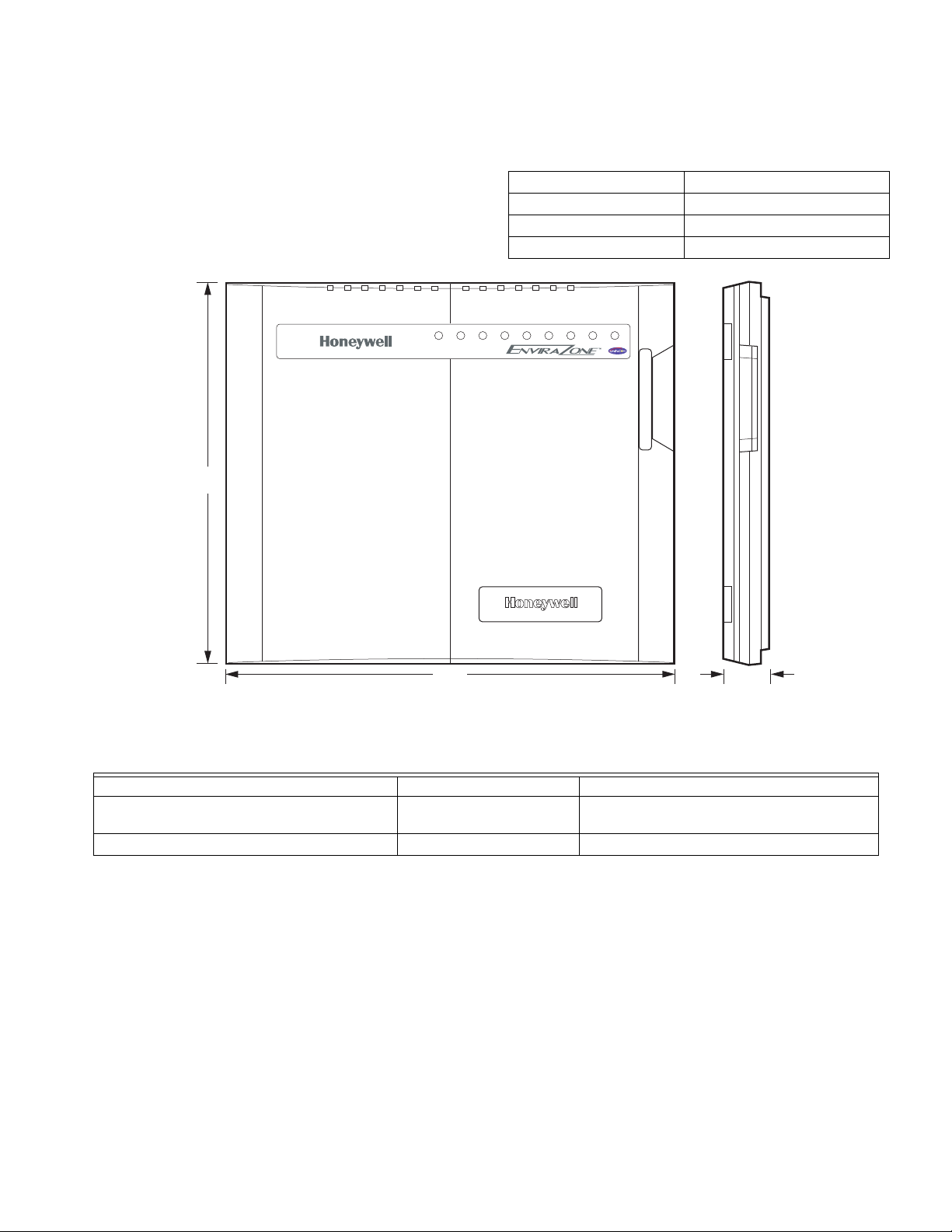
Dimensions: 12-3/4 in. W x 10-3/4 in. H x 1-7/8 in. D.
See Fig. 1.
Finish: W8835: Taupe cover, olive-gray base.
Mounting: Mounts with four screws (provided) through holes
in cabinet back (wall anchors provided).
Wiring: Eighteen-gauge wire for all equipment and system
connections.
Wiring Connections:
EnviraCom: Four terminal strips (each with three terminals
labeled 1, 2, 3).
Dampers: Three terminal strips labeled M6 (Closed),
M4 (Open), M1 (Common).
Transformer 1: R (hot), C (Common).
Transformer 2: T1 (hot), T2 (Common).
Equipment: Rc, Rh, W1/E, W2, W3/Aux, Y1, Y2, G, O/B.
Humidifier: HUM, HUM.
Dehumidifier: DHUM, DHUM.
Ventilator: VENT, VENT.
Thermostats:
VisionPRO® IAQ TH9421 or FocusPRO THM5320C Thermo-
stats controls single- or multi-stage conventional and heat
pump equipment.
Accessories:
For required accessories, see Table 2. Optional accessories
include the W8735 Telephone Access Module for
telephone dial-in and dial-out capability, and the W8703
Damper Interface Module to control additional zones.
ORDERING INFORMATION
When purchasing replacement and modernization products from your TRADELINE® wholesaler or distributor, refer to the
TRADELINE® Catalog or price sheets for complete ordering number.
If you have additional questions, need further information, or would like to comment on our products or services, please write or
phone:
1. Your local Honeywell Automation and Control Products Sales Office (check white pages of your phone directory).
2. Honeywell Customer Care
1885 Douglas Drive North
Minneapolis, Minnesota 55422-4386
In Canada—Honeywell Limited/Honeywell Limitée, 35 Dynamic Drive, Toronto, Ontario M1V 4Z9.
International Sales and Service Offices in all principal cities of the world. Manufacturing in Australia, Canada, Finland, France,
Germany, Japan, Mexico, Netherlands, Spain, Taiwan, United Kingdom, U.S.A.
68-0258ES—04 2
Page 3
W8835 ENVIRAZONE PANEL
Dampers:
See Table 1 for suggested dampers. Dampers are connected to
M1 Common, M4 Open, and M6 Closed (see Fig. 5 through 8
for hookups). Connect no more than five ARD or ZD dampers
to an individual zone.
Connect no more than five ARD or ZD dampers to the panel
when using one 40 VA transformer; connect no more than
ten ARD or ZD dampers when using two 40 VA transformers.
HEAT COOL PURGE FAN EM. HT. COMM ZONE 1 ZONE 2 ZONE 3
10-3/4
(273)
Use SDCR for additional dampers required. If using RRD
dampers, refer to RRD installation instructions for maximum
number of dampers.
Motor Terminal Damper Action
Common/M1 Common
Open/M4 Power Open
Closed/M6 Power Close
TM
12-3/4
(324)
1-7/8
(47)
M20594
Fig. 1. W8835 dimensions in in. (mm).
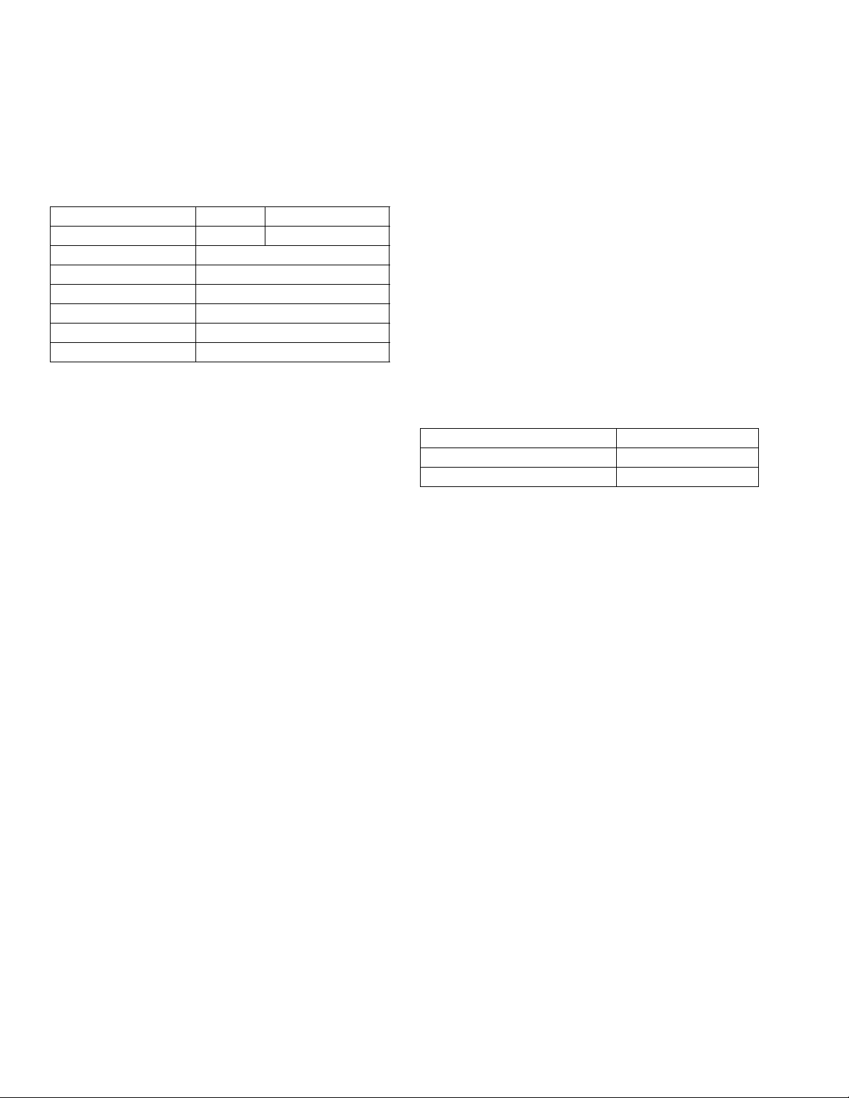
Table 1. Recommended Dampers
Honeywell Damper Type Round Rectangular
For systems > 2000 cfm. MARD or RRD For recommended dampers, call the Honeywell
Zoning Hotline at 1-800-828-8367.
For systems <= 2000 cfm. ARD or RRD ZD
3 68-0258—04
Page 4
W8835 ENVIRAZONE PANEL
CAUTION
CAUTION
A
Table 2. Required Accessories (Not Supplied with Panel).
Accessory Description
40 VA transformers
High and low limit sensor
AT140A1042
C7835A1009
Round static pressure regulator damper SPRD7
SPRD8
SPRD9
SPRD10
SPRD12
SPRD14
SPRD16
Rectangular static pressure regulator damper SPRD12x8
SPRD12x10
SPRD12x12
SPRD20x8
SPRD20x10
SPRD20x12
a
Supplied in the Y8835 kits.
INSTALLATION
Mounting
Bypass Rating
(cfm)
a
a
—
—
300
400
600
750
1200
1800
2400
1000
1200
1400
1600
2000
3000
RETURN
AIR
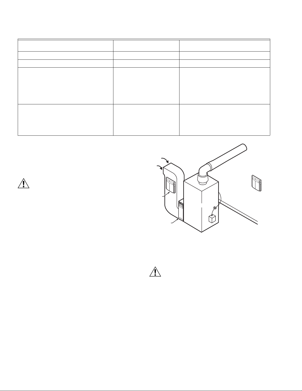
Equipment Damage Hazard.
Do not mount W8835 inside HVAC equipment.
Mount only on wall or on cold air return.
1. Mount the thermostats in each zone of the living space
using the installation instructions provided with each
thermostat.
2. Mount the dampers in the ductwork using the installation
instructions provided with each damper.
3. Mount the W8835 EnviraZone Panel near the HVAC
equipment; locate it on a wall or on the cold-air return.
See Fig. 2.
4. Level the W8835 for appearance only.
W8835
IR CLEANER
E
LE
CTRONI
C
AIR CLEANER
FURNACE
W8835
M31121
Fig. 2. W8835 mounting location.
Wiring
Voltage Hazard.
Can cause electrical shock or equipment damage.
Disconnect power before continuing installation.
Wiring must comply with applicable codes, ordinances,
and regulations.
68-0258—04 4
Page 5
W8835 ENVIRAZONE PANEL
12 3
12 3
12 3
L
C
RH
RC
W1 /E
W2
W3/AU X
Y1
Y2
G
O/ B
HU M
HU M
DE HUM
DE HUM
VE NT
VE NT
R
C
T1
T2
ZONE 1
M6 M4 M1
ZONE 2
M6 M4 M1
ZONE 3
M6 M4 M1
1 2 3 1 2 3 1 2 3 1 2 3
DA MP ER S E NV IR AC OM BUS
DAM PER
XF RM
EN VI RACO M
XF RM
RE MO VE JU M PER S IF
T1 AND T2 ARE USED
HE AT CO OL ZO NE 1 CO M EM HE AT FA N PU RG EZ ON E 3 ZO NE 2
W8835A
DI P SW IT CH SE TT IN GS
1 SEE TA BL EO NO FF
2 SEE TA BL E1 0
3 EN VI RACO M FU RN NO YE S
4 P URG E TI ME 2 MI N3 .5 MI N
5 P URG E FA NH VA C P ANE L
6 P URG E DAM PE RN O CHG OP EN
7 # CO MP ST AG ES 1 2
8 H E AT FA NH VA C P ANE L
9 H P CHANG EO VE RO B
10 UNU SE D
O
N
1 2 3 4 5 6 7 8 9 10
#1 # 2 CO NV HT ST G
1 1 1
1 0 2
0 1 3
0 0 HP
24 VOLT/40 VA
TR AN SF OR ME R
R
C
L1
L2
R
W1
W2
Y1
Y2
G
C
DO TTE D LI NE S FO R 2ST AG E A PPL IC AT IO NS
SI NG LE TR AN SF OR ME R
H EAT I N G/COOLING SYST EM S
RE QU IR E A JU M PER TO BE
IN ST AL LE D C O NNEC TI NG R H
AND RC (FACTORY INSTALLED) .
12 3
EARD- 6
M31122
POWER-CLOSED/
SPRING-OPEN
ZD DAMPER
POWER-CLOSED/
SPRING-OPEN
ZD DAMPER
POWER-CLOSED/
SPRING-OPEN
ARD DAMPER
C7835A DISCHARGE
AIR SENSOR
LED STATES:
Heat LED Heating Mode
Cool LED Cooling Mode
Purge LED Purge Mode
Fan LED Fan Mode
Em Heat LED Em Heat Mode
COMM LED Communications
ZONE LEDS:
On Damper open or opening
Off Damper closed or closing
MOMENTARY PUSH BUTTONS
Boot Clears Microprocessor
Purge Override Bypass Purge Mode
Discovery Initiates Discovery Mode
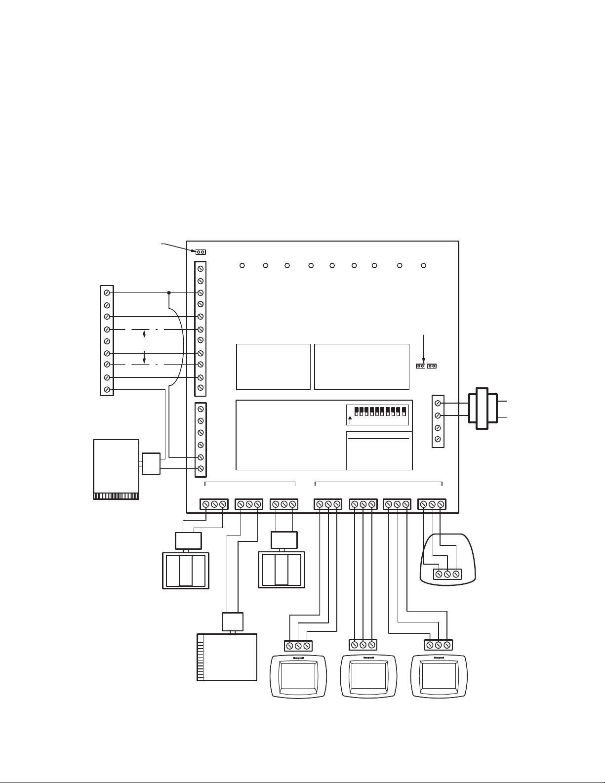
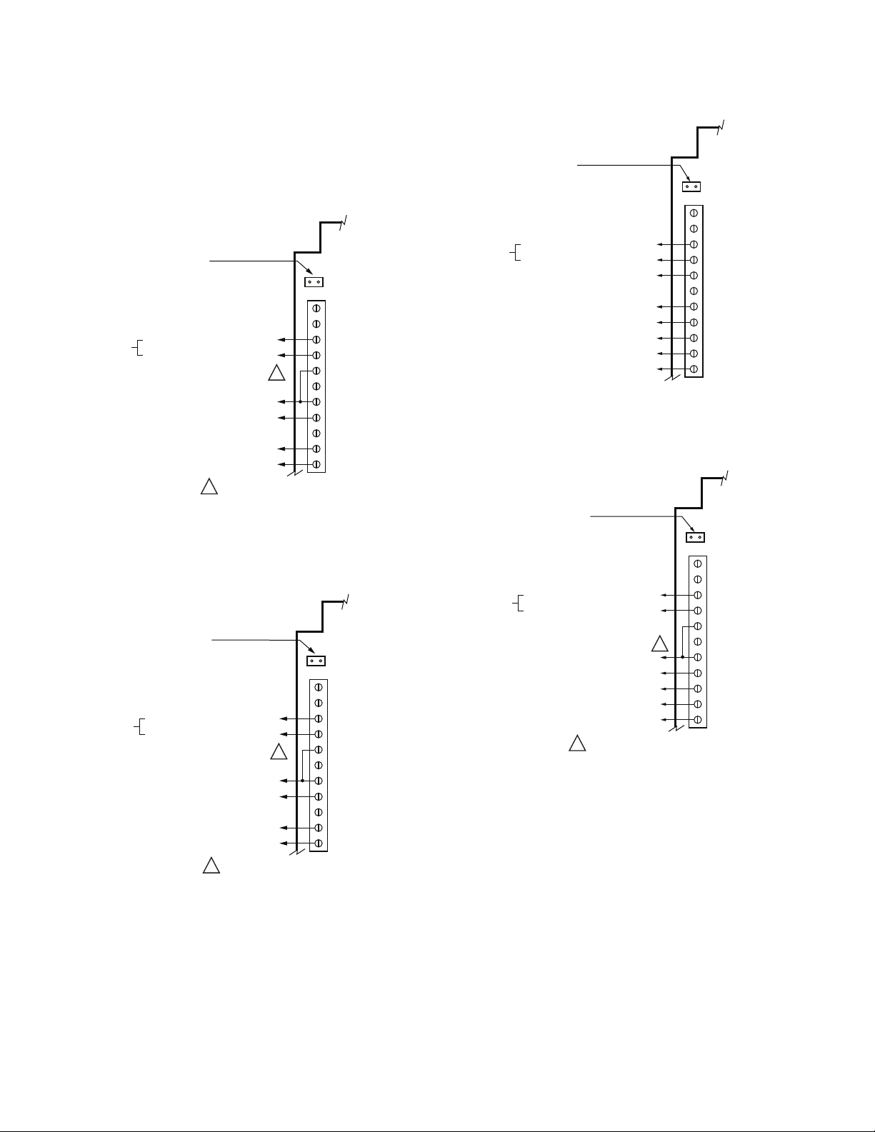
Wiring Thermostats
Run wire from the Thermostat 1, 2, 3 terminals to the
corresponding terminals on any one of the EnviraCom bus
terminal sets. More than one thermostat or other
communicating device can be connected to a bus terminal.
See Fig. 3.
Wiring Equipment
CONVENTIONAL EQUIPMENT
Connect the first stage heat to W1/E, second stage heat to W2,
and third stage heat to W3/Aux. Wire first stage cooling to Y1,
and second stage cooling to Y2. See Fig. 3.
If separate HVAC equipment transformers are used for the
heating and cooling systems, such as for an oil furnace, wire
the heating transformer hot wire to Rh and the cooling
transformer hot wire to Rc. Locate the Rh/Rc jumper above the
equipment terminals and remove the jumper to expose the two
pins.
HEAT PUMP EQUIPMENT
Connect the Y1 terminal to the first stage compressor, and the
Y2 terminal to the second stage compressor. W3/Aux is the
auxiliary heat and W1/E is the emergency heat. If emergency
heat and auxiliary heat use the same piece of equipment,
place a jumper from W3/Aux to W1/E and wire it to the resistive
heat equipment. See Fig. 4 and 5. See Fig. 6 and 7 for twostage heat pump equipment.
Fig. 3. Conventional equipment wiring diagram.
5 68-0258—04
Page 6
W8835 ENVIRAZONE PANEL
For dual fuel equipment using heat pump and fossil fuel,
configure the panel as a heat pump and use a fossil fuel kit. Do
not use the dual fuel functionality of the VisionPRO® IAQ.
Wiring HVAC Equipment
SINGLE TRANSFORMER HEATING/COOLING
SYSTEMS REQUIRE A JUMPER TO BE
INSTALLED CONNECTING R
(FACTORY INSTALLED).
HVAC EQUIPMENT
24 VAC
EQUIPMENT
REVERSING VALVE (COOLING/HEATING)
HEATING TRANSFORMER
COOLING TRANSFORMER
Fig. 4. Wiring single-stage heat pump with separate
Auxiliary and Emergency Heat.
SINGLE TRANSFORMER HEATING/COOLING
SYSTEMS REQUIRE A JUMPER TO BE
INSTALLED CONNECTING R
(FACTORY INSTALLED).
HVAC EQUIPMENT
24 VAC
EQUIPMENT
REVERSING VALVE (COOLING/HEATING)
HEATING TRANSFORMER
COOLING TRANSFORMER
AND R
H
C
AUXILIARY HEAT
COMPRESSOR
FAN RELAY
FIELD INSTALLED JUMPER
1
AND R
H
AUXILIARY HEAT
COMPRESSOR
FAN RELAY
FIELD INSTALLED JUMPER
1
L
C
R
H
R
C
1
W1/E
W
2
W3/AUX
Y
1
Y
2
G
O/B
M31124
C
L
C
R
H
R
C
1
W1/E
W
2
W3/AUX
Y
1
Y
2
G
O/B
M31124
SINGLE TRANSFORMER HEATING/COOLING
SYSTEMS REQUIRE A JUMPER TO BE
INSTALLED CONNECTING R
(FACTORY INSTALLED).
AND R
H
C
HVAC EQUIPMENT
L
C
24 VAC
EQUIPMENT
HEATING TRANSFORMER
COOLING TRANSFORMER
EMERGENCY HEAT RELAY
AUXILIARY HEAT RELAY
FIRST STAGE COMPRESSOR
SECOND STAGE COMPRESSOR
FAN RELAY
REVERSING VALVE (COOLING/HEATING)
R
H
R
C
W
/E
1
W
2
W3/AUX
Y
1
Y
2
G
O/B
M31123
Fig. 6. Wiring two-stage heat pump with separate Auxiliary
Heat.
SINGLE TRANSFORMER HEATING/COOLING
SYSTEMS REQUIRE A JUMPER TO BE
INSTALLED CONNECTING R
(FACTORY INSTALLED).
AND R
H
C
HVAC EQUIPMENT
L
C
24 VAC
EQUIPMENT
HEATING TRANSFORMER
COOLING TRANSFORMER
AUXILIARY HEAT RELAY
FIRST STAGE COMPRESSOR
SECOND STAGE COMPRESSOR
FAN RELAY
REVERSING VALVE (COOLING/HEATING)
FIELD INSTALLED JUMPER
1
1
R
H
R
C
W
/E
1
W
2
W3/AUX
Y
1
Y
2
G
O/B
M31125
Fig. 7. Wiring two-stage heat pump with Auxiliary Heat.
Fig. 5. Wiring single-stage heat pump with Auxiliary Heat.
68-0258—04 6
Page 7
W8835 ENVIRAZONE PANEL
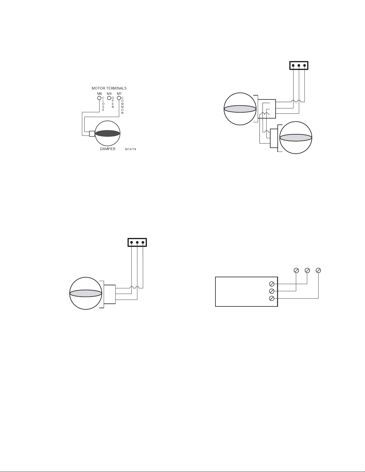
ARD or ZD Dampers
Wire the ARD or ZD Damper to the panel as shown in Fig. 8.
Multiple dampers can be wired in parallel. Up to five ARD or
ZD dampers can be connected in parallel to one zone. If five to
ten dampers are connected to the panel an additional 40VA
transformer must be connected to the panel.
Fig. 8. Wiring ARD or ZD damper to panel.
RRD
Wire the RRD dampers to the panel as shown in Fig. 9. Two or
more RRD can be wired in tandem as shown in Fig 10. Up to
12 RRD can be wired to one zone. Power the panel with one
40VA transformer if up to 12 dampers are connected to the
panel. Power the panel with two 40VA transformers if up to 26
RRD are connected to the panel.
ZONE
1, 2, 3, ETC.
M6 M4 M1
ZONE
1, 2, 3
M6 M4 M1
M 1
M 6
M 4
M1
M6
M4
M31134
Fig. 10. Wiring two RRD dampers in parallel.
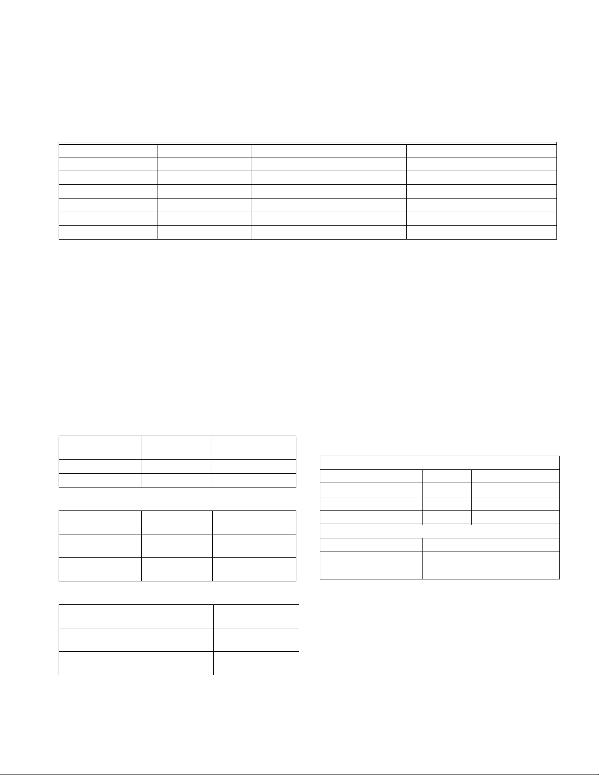
MARD Dampers or Dampers using ML6161
Motor Actuator
Wire the MARD Damper or other damper using the ML6161
Actuator to the panel as shown in Fig. 11. These floating
control actuators are controlled as two-position devices on the
W8835 panel.
The ML6161 motor causes the damper LED to illuminate green
constantly. To restore damper position indication, mount end
switch 201052B onto the ML6161.
M1
M6
M4
M31133
Fig. 9. Wiring RRD damper to panel.
ZONE PANEL
CONNECTIONS
M1 M4
MARD
CW
COM
CCW
M6
M20136A
Fig. 11. Wiring MARD Damper or ML6161 Actuator to
panel.
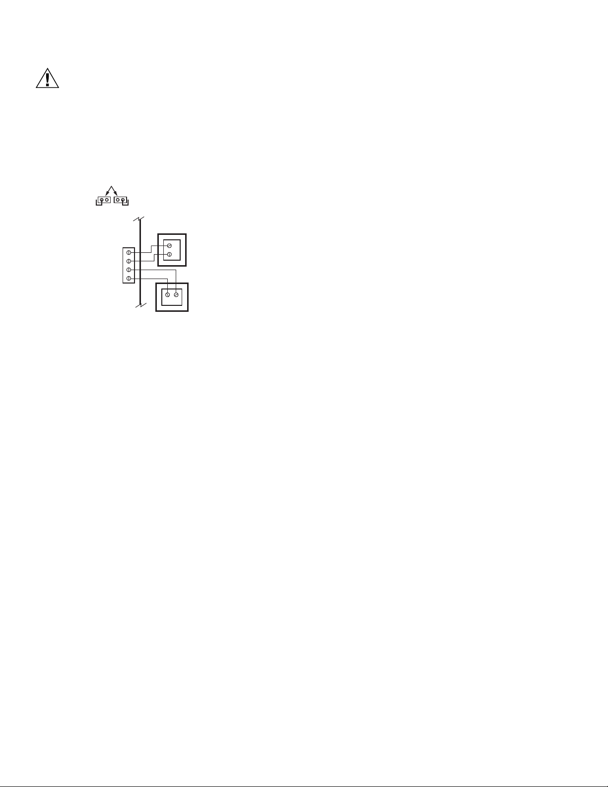
Transformer
Wire the transformers to the panel (see Fig. 12). One 40 VA, 24
Vac transformer is required to operate the panel and up to five
ARD or ZD dampers. The transformer is connected to
terminals R and C. The auxiliary transformer is required if up to
ten dampers are connected to the panel. It is wired to terminals
T1 and T2. If more than five ARD or ZD dampers are required
for one zone of if more than ten ARD or ZD dampers are
required for the W8835, use the Slave Damper Control Relay
(SDCR). Locate the XFRM jumper shown in Fig. 12. These
jumpers are shipped in the open, disconnected position. This is
the correct position when two transformers are used. When
using one transformer to power the panel, place the jumpers in
the closed position. Do this by removing the jumpers and
installing them so they cover both of their respective pins. If
preferred, one 75 VA transformer may be used on this panel
instead of two 40 VA. If this is done, leave the jumpers in the
open, disconnected position and install a jumper between R
and T1. Wire the transformer to R and C.
7 68-0258—04
Page 8
W8835 ENVIRAZONE PANEL
CAUTION
R
C
T1
T2
CR
C
R
24 VAC, 40 VA
TRANSFORMER
(REQUIRED IF
MORE THAN
FIVE DAMPERS)
24 VAC, 40 VA
TRANSFORMER
DAMPER
XFRM
PAN EL
XFRM
M31126
REMOVE XFRM JUMPERS
FROM PINS WHEN USING
TWO TRANSFORMERS
Equipment Damage Hazard.
Incorrect transformer wiring can damage panel.
Wire transformers in phase when one transformer
is wired to R and C and the auxiliary transformer
is wired to T1 and T2.
4. On the W8835 Panel, set the DIP switches.
a. Set DIP switches 1, 2, and 7 to assign the
appropriate number of heating and cooling stages.
See Tables 5 and 6.
b. Configure other DIP switches, as necessary to fit the
application. See Table 6.
5. On each thermostat, enter the Installer Setup procedures
using the VisionPRO® IAQ Installation Instructions and
assign each thermostat a zone number to correspond
with its zone damper.
6. Run Discovery by pressing the Discovery button on the
zone control panel.
7. On each thermostat, enter the Installer Setup
procedures using the Installation Instructions and configure other pertinent Installer Setup options. Program the
thermostat schedule if the default settings are not
desired.
8. Run Discovery by pressing the Discovery button on the
panel.
9. Set Zone one thermostat to heat and raise the setpoint to
call for heat.
a. Verify that the heat LED is red.
NOTE: The furnace heat may not come on immedi-
ately. Allow at least 5 minutes for heat to begin
after the thermostat calls for heat.
Wiring C7835 Discharge Air
Temperature Sensor
Connect wire terminals 1, 2, and 3 to the corresponding
terminals on either the W8835 EnviraZone panel or any other
EnviraCom device such as a thermostat. Refer to C7835
Installation Instructions for configuration. Multiple devices can
be wired in parallel to the each of the 1, 2, 3 terminals.
STARTUP AND CHECKOUT
1. Verify that the equipment, thermostats, transformer, and
Discharge Temperature Sensor are wired correctly. If
one transformer is powering the panel, install the XFRM
jumper. If two transformers are powering the panel, leave
the XFRM jumper in the open position.
2. Power up the W8835. Verify that all LEDs except COM
illuminate for five seconds.The board should then enter
the Purge mode with all dampers open. The damper
LEDs are green to indicate the dampers are open.
The COM LED begins to blink.
3. Press the Purge Override button to terminate the Purge
mode.
68-0258—04 8
Fig. 12. Wiring transformer(s) to panel.
b. Verify that Zone one LED remains green.
c. Verify that all other zone LEDs are not illuminated.
d. Change thermostat mode from Heat to Off.
10. Set Zone two thermostat to heat and raise the setpoint to
call for heat.
a. Verify that the heat LED is red.
b. Verify that Zone two LED remains green.
c. Verify that all other zone LEDs are not illuminated.
d. Change thermostat mode from Heat to Off.
11. Alternatively, set a thermostat to Cool, lower the
setpoint to call for cooling, wait five minutes, and verify
correct operation.
OPERATION
Sequence of Operation
When there is no call for heat, cool or fan, the board is in the
idle mode, indicated with no system LEDs illuminated, see
Table 3. Damper LEDs are green to indicate open. On a call for
heat, cool, or fan, the calling zone damper stays open and the
damper LED remains illuminated; the other zone dampers
close and corresponding damper LEDs do not illuminate.
The W8835 panel energizes the HVAC equipment and
conditioned air is delivered to the calling zone. The heat LED
(red), cool LED (green), or fan LED (green) illuminates to
indicate equipment operation.
The fan LED illuminates only on a call for fan; it does not
illuminate during a call for heat or cool. When the heat/cool call
is satisfied, the system enters the Purge mode, indicated by
the Purge LED (yellow). Damper positions either remain in the
same positions as at the end of the call for heat or cool
(default) or open, depending on the position of DIP switch 6.
After purge, all dampers return to the Open position.
Page 9
COM LED Operation
The green COM LED flickers as the W8835 communicates
with the other EnviraCom devices:
LED blinks rapidly—indicates device is currently
transmitting information on the communications bus.
W8835 ENVIRAZONE PANEL
LED blinks once—indicates device received and
acknowledged a message.
LED on constantly— indicates panel failure. Replace panel.
LED off constantly—indicates a wiring problem.
Table 3. LED Indicators
LED Color Illuminated Not Illuminated
Heat Red Heat call. No heat calls.
Cool Green Cool call. No cool calls.
Purge Amber Purge mode. Not in Purge mode.
Fan Green Fan only call. No fan only call.
Em Heat Red Emergency Heat mode. Not in Emergency Heat mode.
Zone 1, 2, 3 Green Damper is open or opening. Damper is closed or closing.
b
An LED change precedes the corresponding relay change by as much as six seconds.
Purge Mode
At the end of every call for heat or cool, the panel enters a
Purge mode. DIP 4 configures the panel to purge for two
(default) or three and one-half minutes. DIP switch 5
configures the panel or the HVAC equipment to operate the fan
during purge.
The Purge LED lights to signal that the system is in the Purge
mode. Pressing the purge override button overrides the Purge
mode.
Individual Zone Fan Control
When all zones are satisfied, the fan switch of each thermostat
controls the fan operation for that zone. When the fan setting is
“ On”, the fan is energized, the fan LED illuminates and the
dampers close to zones where the fan setting is “Auto”. If there
is a call for heat or cool during this time, the fan mode ceases,
and the heat or cool call is honored. When the zone calling is
satisfied, and Purge mode has ended, the fan call resumes.
b
Single and Multi-Stage Conventional
Unless there is a new call for heat or cool during the Purge
mode, all dampers are moved to the Open position at the end
of purge. DIP switch 6 is used if it desired to open all dampers
during the Purge mode.
Table 4. Purge Configuration
DIP Switch
Number
4 Off (Down) 3.5 minutes purge
4 On (Up) 2 minutes purge
Table 5. Fan Control Configuration
DIP Switch
Number
5 Off (Down) Panel control of fan
5 On (Up) HVAC control of fan
Status Purge
Status Fan Control
in Purge
in Purge
Heat Operation
The panel can control up to three stages of heating and two
stages of cooling based on thermostat demand. Set DIP
switches 1 and 2 for 1, 2 or 3 stages of heat. Set DIP switch 7
for one or two stages of cooling.
Table 7. Conventional Equipment Configuration
1 Stage Cooling
Equipment Type DIP 1 DIP 2
1 Stage Conventional On (Up) On (Up)
2 Stage Conventional On (Up) Off (Down)
3 Stage Conventional Off (Down) On (Up)
2 Stage Cooling
Cooling Stage DIP7
1 Stage On (Up)
2 Stage Off (Down)
Table 6. Purge Damper Configuration
DIP Switch
Number
6 On (Up) Last zone(s) calling
6 Off (Down) Open all dampers
Status Purge Damper
open during Purge
during Purge
9 68-0258—04
Page 10
W8835 ENVIRAZONE PANEL
Heat Pump Operation
The panel can control one or two compressor stages plus
auxiliary heat. Set DIP switch 1 and 2 to Off; set DIP switch 7
to On for a single-stage compressor and to Off for a two-stage
compressor.
Table 8. Heat Pump Equipment Configuration
Equipment Type DIP 1 DIP 2
Heat Pump Off (Down) Off (Down
Compressor Stages DIP 7
1 Stage On (Up)
2 Stage Off (Down
Heat Pump Changeover DIP 9
O (Cool) On (Up)
B (Heat) Off (Down
Wire the reversing valve to the O/B equipment terminal. DIP
switch 9 configures this terminal to operate as an O (cool) or
B (heat) changeover terminal.
Hydronic Heat Operation
The W8835 is a forced air panel. However, it can be wired to
control hydronic valves as shown in figure 13. To control
valves or circulators on a hydronic panel, see figure 14.
Thermostat Operation
Dual Fuel Equipment
The W8835 can operate Dual fuel equipment when used with
an external fossil fuel kit. Locate the thermostat on the fossil
fuel kit instructions and wire the W8835 equipment terminals
there.
Emergency Heat Control
Emergency heat is defined as using an auxiliary heat source
without using the heat pump. The W8835 energizes the E
terminal on a call for emergency heat. The thermostat system
switch is set to Em Heat to engage this function. When active,
any zone calling for heat uses Emergency Heat, not the
compressor.
The panel energizes W3 as auxiliary heat with the Y1 and Y2
for compressor control in when not in emergency heat.
Manual and Automatic Changeover Operation
Each of the thermostats can be set for manual or automatic
changeover. If one or more thermostats call for cooling while
one or more thermostats call for heating, the panel attempts to
satisfy the greatest demand first.
Then, based on the relative demand for heating and cooling,
the panel intelligently switches between heating and cooling.
The system attempts to satisfy both the heating and cooling
demands, and does not lock out one demand in favor of the
other.
Discovery
Discovery is an automatic system configuration program where
the panel configures itself to operate with controls connected to
the EnviraCom bus. The panel enters Discovery when the
Discovery button on the panel is pressed.
Rebooting Microprocessor
To reset the microprocessor, press and release the Boot
button. The system reboots and enters the Purge mode.
EnviraCom Furnace
For furnaces with EnviraCom communications built in,
configure the panel as shown below. In this case, no
conventional equipment wiring is necessary because the
W8835 uses the 3-wire EnviraCom bus to control the HVAC
equipment. In these installations, the panel is powered from
the HVAC equipment via the 1, 2, 3 wires. Because of this, the
transformer R and C terminals on the W8835 are not used.
Instead, leave the XFMR jumpers in their default disconnected
position and wire the transformer to T1 and T2.
Table 9. Furnace Type Configuration
Type of Equipment DIP 3
Conventional On (Up)
EnviraCom Off (Down)
Humidity, De-humidity and
Ventilation Control
The panel can control humidity, de-humidity, and ventilation by
receiving messages from the VisionPRO® IAQ thermostat.
The thermostat designated as zone 1 will have control of these
functions. Configure this thermostat as found in the installation
instructions for the thermostat.
The humidity, de-humidity, and ventilation terminals are all drycontact terminals; the relay contacts close when active. So
devices that need dry contact control like a ventilator can be
wired directly to the VENT terminals, or a steam humidifier can
be wired directly to the HUM terminals. Devices that need to be
powered like a ventilation damper or some models of
evaporative humidifiers are wired using the VENT or HUM
terminals wired through the R terminal as shown in Fig. 3.
If using a Honeywell TrueSteam humidifier, configure the zone
one VisionPRO IAQ thermostat installer setup #374 to "3", and
wire the TrueSteam GF terminal to the HVAC fan terminal, and
wire the TrueSteam GT terminal to the G on the W8835.
NOTE: When controlling a steam humidifier, set all thermo-
stats to HEAT. Do not set thermostats to AUTO. This
prevents the panel from humidifying on zone 1, when
another zone is calling for cooling. Alternatively, set
zone 1 thermostat Installer Setup 374 to “2” to allow
humidification only during calls for heat.
68-0258—04 10
Page 11

W8835 ENVIRAZONE PANEL
Discharge Air Temperature Sensor
DATS
The C7835A1009 Discharge Air Temperature Sensor (included
in the Y8835 kits) is a supply-duct-mounted temperature
sensor probe used to control capacity and prevent high plenum
temperatures or coil-icing. The sensor is wired to the
EnviraCom bus using three wires. When a high or low limit is
reached, the panel shuts off the equipment and keeps the fan
operating for a minimum of two and one-half minutes. After this
time, and any applicable minimum-off times imposed by the
HVAC equipment. It re-energizes the equipment when the
discharge air has recovered by ten degrees. When the high or
low limit is exceeded, the Heat (red) or Cool (green) LED on
the DATS flashes.
When the DATS is in a limit condition, the Heat, Cool and
Purge LEDs on the W8835 panel continue to operate as if the
DATS were not turning the equipment off.
The high and low limit is set on the DATS. The high
temperature limit is set from 110°F to 160°F with a small
screwdriver or using fingers and the low limit is set at 40°F or
48°F degrees with a jumper.
Circuit Breaker Protection
A built-in thermal circuit breaker protects the EnviraZone panel
against shorts in the damper wiring and EnviraCom bus. It
does not protect against shorts in the HVAC equipment wiring
into the panel.
When the circuit breaker is tripped, none of the LEDs illuminate
and the yellow rectangular component located bottom center
on the panel is hot to touch.
• Remove power to the panel for at least five minutes to allow
the circuit breaker to cool off and reset.
• To eliminate the short, verify the dampers and transformer
wiring.
Fan On In Heat
The system blower can be set to come on with a call for heat
as required for hydro-air or electric heat systems. Set the
blower function using DIP switch 8. When configured for heat
pump, this DIP switch is not used.
Table 10. Fan-in-heat Configuration
DIP Switch 8 Fan Control
Off (Down) Fan on in heat by panel.
On (Up) HVAC control of fan.
Adding Additional Zones
Connect one W8703 to the EnviraCom bus to expand the
system up to six zones or connect two W8703 to control up to
nine zones:
• Wire the first three zone dampers and thermostats to the
W8835 Envirazone Panel.
• Wire the additional dampers to the W8703 panels.
• Set the DIP switches on the W8703 to correspond to the
zones being controlled. See W8703 Installation Instructions.
• Wire terminals 1, 2, and 3 from the additional thermostats to
terminals 1, 2, and 3 on any of the panels.
TROUBLESHOOTING
Table 11. Troubleshooting
Symptom Possible Cause Action
No LEDs are Illuminated. No power to the board. Check for 24 Vac (±10%) across R and C.
Transformers out of phase. If 48 Vac across R and T1, reverse T1 and T2 wires.
Shorted wire. Check thermal circuit breaker. If hot, a short exists in wiring.
Damper LEDs on, but no
other LEDs illuminate on a
call for heat, cool, or fan.
Heat pump operates
incorrectly or not at all.
No damper LEDs are
illuminated.
Error 35 or 39 message on
thermostats.
Wait is continuously in the
thermostat display
Insufficient voltage. Check for 24 Vac (±10%) across R and C.
Incorrect configuration. Check jumpers and DIP switches for correct configuration.
Incorrect wiring. Verify equipment terminals wiring.
Incorrect configuration. Verify DIP switches configuration.
Incorrect configuration. Verify that XFRM jumpers are set correctly.
Incorrect zone numbers. Verify the thermostat zone numbers are set correctly (1,2,3 etc)
Incorrect configuration Verify dip switch 3 is set to conventional (Up) position. If
controlling a heat pump, verify that thermostats are not configured
to lockout the compressor based on outdoor temperature.
(This feature is not used on zoned applications)
11 68-0258—04
Page 12

Table 12. DIP Switches 1 and 2
Equipment Type DIP 1 DIP2
1 Stage Conventional On (up) On (up)
2 Stage Conventional On (up) Off (down)
3 Stage conventional Off (down) On (up)
Heat Pump Off (down) Off (down)
Table 13. DIP Switches 3–10
DIP Switch Function On (Up, Default) Off (Down)
3 Type of furnace Conventional/non-communicating EnviraCom Communicating
4 Purge time Two minutes 3.5 minutes
5 Fan control during purge HVAC controlled Panel controlled
6 Damper control during purge Last zone(s) calling open during purge Open all dampers during purge
7 Heat pump compressor
stages
8 Fan control in heat Fan controlled by panel in cool and
9 Heat pump changeover O (Cool changeover) B (heat changeover)
10 Not used — —
One stage Two stages
Fan controlled by panel in heat and
HVAC equipment in heat
cool
Page 13

W8835A controlling a zone valve or circulator relay panel
W8835 ENVIRAZONE PANEL
FAN RELAY CENTER
24 VOLT TRANS
2
C
CONDENSER
C
Jumper in place
L
C
R
Y
G
Y
1
3
1
Rh
Rc
W1/E
W2
W3/AUX
Y1
Y2
G
O/B
HUM
HUM
DHUM
DHUM
VENT
VENT
ZONE 1
M6 M4 M1
NOTE:
FOR THE AQUASTAT AND CIRCULATOR WIRING,
SEE THE INSTALLATION INSTRUCTIONS FOR
THE HYDRONIC RELAY PANEL.
DAMPERS
M6 M4 M1
ZONE 2
W8835A
O
N
1 2 3 4 5 6 7 8 9 10
ALL SWITCHES ARE UP
ZONE 3
M6 M4 M1
1 2 3
EN
1
3
1
3
1
R (T) W (T) R (T) W (T) R (T) W (T)
ZONE 1
CIRCULATOR OR ZONE VALVE RELAY PANEL
1
R 8222B1067 RELAYS
2
IF IT IS A HEAT-ONLY APPLICATION THE R AND C WILL COME FROM A TRANSFORMER RATHER THAN A FAN
RELAY CENTER. IN THAT APPLICATION THE Y AND G SHOWN IN THIS DIAGRAM WOULD NOT BE USED.
1
ZONE 2
3
1
1
1
ZONE 3
Fig. 13. Wiring reference, Zone Valve or Circulator Relay Panel
M31127
13 68-0258—04
Page 14

W8835 for hot-water zone valves without a hydronic relay panel
L
C
Rh
Rc
W1/E
W2
W3/AUX
Y1
Y2
G
O/B
Cooling
W8835A
THIS DIAGRAM SHOWS HOW THE W8835 GETS WIRED TO ZONE
VALVES AND AN AIR-CONDITIONER FOR HOT WATER HEATING
AND FORCED AIR COOLING APPLICATIONS. FOR COMPLETE
AQUASTAT WIRING, SEE THE AQUASTAT INSTRUCTIONS
ZONE 1
M6 M4 M1
ZONE 2
M6 M4 M1
ZONE 3
M6 M4 M1
TH TR
TH TR
TH TR
Honeywell V8043
zone valves
End switch End switch End switch
R (T) W (T)
L8124 or L8148
aquastat
Remove Rh/Rc jumper
R
Y
G
M31128
W8835 ENVIRAZONE PANEL
Fig. 14. Wiring Reference Hot Water Zone Valves
68-0258—04 14
Page 15

W8835 ENVIRAZONE PANEL
15 68-0258—04
Page 16

Automation and Control Solutions
Honeywell International Inc. Honeywell Limited-Honeywell Limitée
1985 Douglas Drive North 35 Dynamic Drive
Golden Valley, MN 55422 Toronto, Ontario M1V 4Z9
customer.honeywell.com
® U.S. Registered Trademark
© 2009 Honeywell International Inc.
68-0258—04 E.K. Rev. 08-09
Page 17

68-0258ES-04
Panel EnviraZone W8835
INFORMACIÓN DEL PRODUCTO
APLICACIÓN
El panel EnviraZone W8835 controla equipos de una sola
etapa, de varias etapas, convencionales o bombas de calor
para calefacción y refrigeración. Controla tres zonas y puede
ampliarse hasta nueve zonas con dos módulos adicionales de
interfase del humidificador (DIM) W8703A.
Para obtener información en Internet:
http://yourhome.honeywell.com.
Para obtener asistencia técnica, comuníquese al siguiente
número: 1-800-828-8367.
Para obtener más información sobre los productos de
Honeywell para mejorar la calidad del aire interior, visite:
http://yourhome.honeywell.com
siguiente número: 1-800-345-6770 x531.
*Agencia de Protección Ambiental de los Estados Unidos (EPA). Estados y
tendencias de la calidad de aire nacional, de 1999.
**Indoor Air Pollution, An Introduction for Health Professionals.
del Gobierno de los EE. UU. N.º 1994-523-217/81322.
o comuníquese con el
EPA, Imprenta
IMPORTANTE
Lea estas instrucciones y consérvelas en sus
archivos.
Contenidos
Aplicación ......................................................................... 1
Características ................................................................. 2
Especificaciones ............................................................... 2
Información acerca de los pedidos ................................... 2
Instalación ........................................................................ 4
Inicio y revisión ................................................................. 8
Funcionamiento ................................................................ 9
Solución de problemas ..................................................... 12
Page 18

PANEL ENVIRAZONE W8835
CARACTERÍSTICAS
• Controla hasta tres etapas de calefacción y dos etapas
de refrigeración en equipos de una sola etapa, de
varias etapas, convencionales o bombas de calor.
• Controla hasta tres zonas y puede ampliarse hasta
nueve zonas con dos DIM W8703A.
• Utiliza termostatos de comunicación VisionPRO® IAQ
o FocusPRO para cambio automático o manual por
zona.
• Admite controles de deshumidificación,
humidificación y ventilador.
• El temporizador de purgado protege el equipo entre las
órdenes de refrigeración o calefacción con la opción de
ventilador controlado por el equipo HVAC o por el panel.
• Los LED del humidificador de zona y del sistema
indican el estado del humidificador y del sistema.
• Control del ventilador para zona individual.
• Admite el sensor de temperatura de aire de descarga
para control de capacidad con límites superiores e
inferiores ajustables e indicación de falla del equipo.
• Controla equipos de combustible dual si se utiliza con
un kit de combustible fósil externo.
ESPECIFICACIONES
Calificacione de entrada:
Voltaje: 20-30 V CA, 50/60 Hz.
Electricidad: 11 VA nominal, Clase II.
Calificaciones de salida (reguladores y equipos de calefacción, ventilación y aire acondicionado):
1,5 A por ciclo, 200 000 ciclos (30 V CA) 3,5 A de corriente de
entrada.
1,5 A por ciclo, 100 000 ciclos (30 V CA) 7,5 A de corriente de
entrada.
Rangos de humedad:
90% HR a 95 °F, sin condensación
Rangos de temperatura:
Envío: -20 a 120 °F.
En funcionamiento: -40 a 150 °F.
LED:
LED de modo del SISTEMA (5) utilizados para comunicar el
estado del equipo:
Calor rojo: modo Heat (calefacción).
Frío verde: modo Cool (refrigeración).
Purgado amarillo: modo Purge (purgado).
Ventilador verde: modo Fan (ventilador).
Luz de emergencia roja: modo Emergency Heat (calefac-
ción de emergencia).
LED de ZONA (3) utilizados para comunicar el estado del
humidificador:
Verde: los humidificadores están abiertos o se están
abriendo.
Sin color: los humidificadores están cerrados o se están
cerrando.
Sin color: los humidificadores están cerrados o se están
cerrando.
Verde intermitente: el panel recibió o está transmitiendo infor-
mación.
Sin color: las comunicaciones están suspendidas.
Dimensiones: 12 3/4 in de ancho x 10 3/4 in de alto x 1 7/8 in
de profundidad. Vea la Fig. 1.
Acabado: W8835: Cubierta marrón topo con base gris.
Montaje: Montaje mediante cuatro tornillos (suministrados)
colocados a través de los orificios de la parte posterior del
gabinete (se suministran anclas de expansión).
Cableado: Cable de calibre 18 para todas las conexiones del
sistema y del equipo.
Conexiones de cableado:
EnviraCom: Cuatro regletas de conexiones (cada una con
tres terminales designados 1, 2, 3).
Humidificadores: Tres regletas de conexiones designados M6
(cerrado), M4 (abierto), M1 (común).
Transformador 1: R (calor), C (común).
Transformador 2: T1 (calor), T2 (común).
Equipo: Rc, Rh, W1/E, W2, W3/Aux, Y1, Y2, G, O/B.
Humidificador: HUM, HUM.
Deshumidificador: DHUM, DHUM.
Ventilador: VENT, VENT.
Indicador de fallas de la bomba de calor: L, C.
Termostatos:
Los termostatos VisionPRO® IAQ TH9421 o FocusPRO
THM5320C controlan equipos de una o varias etapas, con-
vencionales o de bomba de calor.
INFORMACIÓN PARA PEDIDOS
Cuando compre productos de reemplazo y modernización a su mayorista o distribuidor de TRADELINE®, refiérase al catálogo o
listas de precios de TRADELINE® para tener el número de pedido completo, o especifique:
1. Número del modelo
2. Voltaje.
Si tiene preguntas adicionales, si necesita más información, o si quisiera dar sus comentarios sobre nuestros productos o
servicios, escriba o llame a:
1. Su oficina de ventas local de Automatización y control desenlace (consulte las páginas blancas de su directorio telefónico)
2. Honeywell Customer Care
1885 Douglas Drive North
Golden Valley, MN 55422-4386
En Canadá : Honeywell Limited/Honeywell Limitée, 35 Dynamic Dr., Toronto, Ontario, M1V 4Z9. Oficinas internacionales de
ventas y servico en todas las principales ciudades de mundo. Manufactura en Australia, Canadá, Finlandia, Francia, Alemania,
Japón, México, los Países Bajos, España, Taiwán, Reino Unido, EE.
68-0258ES—04 2
Page 19

PANEL ENVIRAZONE W8835
Accesorios:
Para ver los accesorios necesarios, consulte la Tabla 2. Los
accesorios opcionales incluyen el módulo de acceso
telefónico W8735 para teléfonos con capacidad de marcación interna y externa, y el módulo de interfaz para regulador W8703 para el control de zonas adicionales.
HEAT COOL PURGE FAN EM. HT. COMM ZONE 1 ZONE 2 ZONE 3
Reguladores:
Consulte la Tabla 1 para ver los reguladores sugeridos. Los
reguladores están conectados a M1 común, M4 abierto y
M6 cerrado (ver Fig. 5 a 8 para las conexiones). No conecte
más de cinco reguladores ARD o ZD a una zona individual.
No conecte más de cinco reguladores ARD o ZD al panel
cuando se utiliza un transformador de 40 VA; no conecte
más de diez reguladores ARD o ZD cuando se utilizan dos
transformadores de 40 VA. Utilice un SDCR (relé plano de
control de regulador) para los reguladores adicionales
necesarios. Si utiliza reguladores RRD, consulte las
instrucciones de instalación de un RRD para ver el número
máximo de reguladores.
Terminal del motor Acción del reguladores
M1 (común) Común
M4 (abierto) Suministro de energía abierto
M6 (cerrado) Suministro de energía cerrado
TM
273
(10-3/4)
324
(12-3/4)
Fig. 1. Dimensiones del W8835 en pulgadas (mm).
Tabla 1. Reguladore recomendados.
Tipo de reguladore de Honeywell Circular Rectangular
Apertura accionada por energía/cierre
accionado por energía (para sistemas >
MARD or RRD D640/D642 usando el accionador del
motor ML6161
2000 cfm).
Apertura accionada por resorte/cierre
ARD or RRD ZD
accionado por energía (para sistemas <=
2000 cfm).
47
(1-7/8)
MS20594
3 68-0258ES—04
Page 20

PANEL ENVIRAZONE W8835
PRECAUCIÓN
PRECAUCIÓN
MS31121
W8835
ELEC
TRO
NIC AIR
CLEANE
R
AIRE DE
RETORNO
W8835
CALDERA
Tabla 2. : Accesorios necesarios (no incluidos con el panel).
Accesorio Descripción
Transformadores de 40 VA AT140A1042 —
Protector de capacidad C7835A1009 —
Humidificador circular con regulador de
presión estática
SPRD7
SPRD8
SPRD9
SPRD10
SPRD12
SPRD14
SPRD16
Humidificador rectangular con regulador de
presión estática
SPRD12x8
SPRD12x10
SPRD12x12
SPRD20x8
SPRD20x10
SPRD20x12
INSTALACIÓN
Montaje
Rango de desviación
(cfm)
300
400
600
750
1200
1800
2400
1000
1200
1400
1600
2000
3000
Peligro de daño en el equipo.
No coloque el W8835 dentro del equipo HVAC.
Colóquelo sólo sobre la pared o en la toma de retorno
de aire frío.
1. Coloque los termostatos en cada zona del hogar
siguiendo las instrucciones de instalación suministradas
con cada termostato.
2. Monte los humidificadores en la red de conductos utili-
zando las instrucciones de instalación suministradas con
cada humidificador.
3. Monte el panel EnviraZone W8835 cerca del equipo
HVAC; colóquelo sobre una pared o en la toma de
retorno de aire frío. Vea la Fig. 2.
4. Nivele el W8835 sólo para presentarlo.
Fig. 2. Ubicación de montaje del W8835.
Cableado
Peligro de alta tensión.
Puede ocasionar descargas eléctricas o dañar el
equipo.
Desconéctelo de la fuente de energía antes de
continuar la instalación.
El cableado debe cumplir con los códigos, las ordenanzas y
las reglamentaciones correspondientes.
68-0258ES—04 4
Page 21

PANEL ENVIRAZONE W8835
12 3
12 3
12 3
L
C
RH
RC
W1 /E
W2
W3/AU X
Y1
Y2
G
O/ B
HU M
HU M
DE HUM
DE HUM
VE NT
VE NT
R
C
T1
T2
ZONE 1
M6 M4 M1
ZONE 2
M6 M4 M1
ZONE 3
M6 M4 M1
1 2 3 1 2 3 1 2 3 1 2 3
DA MP ERS
DAMPER
XFRM
EN VI RACO M
XF RM
QUITE LOS PUENTES
SI UTILIZA T1 Y T2
HEAT
W8835A
DI P SW IT CH SE TT IN GS
1 SEE TA BL E
OFF
2 SEE TA BL E1 0
3 EN VI RACO M FU RN ON OFF
4 P URG E TI ME 2 MI N3 .5 MI N
5 P URG E FA NH VA C P ANE L
6 P URG E DAM PE RN O CHG OPEN
7 # CO MP ST AG ES 1 2
8 H E AT FA NH VA C P ANE L
9 H P CHANG EO VE RO B
10 UNU SE D
O
N
1 2 3 4 5 6 7 8 9 10
#1 #2 CO NV HT ST G
1 1 1
1 0 2
0 1 3
0 0 HP
TRANSFORMADOR
DE 24 V/40 VA
R
C
L1
L2
R
W1
W2
Y1
Y2
G
C
LÍNEAS DE PUNTOS
PARA APLICACIONES
DE LA ETAPA 2
LOS SISTEMAS DE CALEFACCIÓN/
REFRIGERACIÓN DE UN SOLO
TRANSFORMADOR REQUIEREN
LA INSTALACIÓN DE UN PUENTE
PARA CONECTAR RH Y RC
(INSTALADOS EN LA FÁBRICA).
12 3
EARD- 6
MS31122
HUMIDIFICADOR ZD CON
CIERRE ACCIONADO POR
ENERGÍA/APERTURA
ACCIONADA POR
RESORTE
HUMIDIFICADOR ZD CON
CIERRE ACCIONADO POR
ENERGÍA/APERTURA
ACCIONADA POR RESORTE
HUMIDIFICADOR ARD CON
CIERRE ACCIONADO POR
ENERGÍA/APERTURA
ACCIONADA POR RESORTE
SENSOR DE AIRE DE
DESCARGA C7835A
LED STATES:
Heat LED Heating Mode
Cool LED Cooling Mode
Purge LED Modo Purge (purgado)
Fan LED Fan Mode
Em Heat LED Em Heat Mode
COMM LED Communications
ZONE LEDS:
On Damper open or opening
Off Damper closed or closing
MOMENTARY PUSH BUTTONS
Boot Clears Microprocessor
Purge Override Bypass Purge Mode
Discovery Initiates Discovery Mode
ON
COOL
PURGE FAN
FM HEAT COM
ZONE 1
ZONE 2 ZONE 3
ENVIRACOM BUS
Cableado de los termostatos
Extienda el cable desde los terminales 1, 2 y 3 del termostato
hasta los terminales correspondientes en uno de los juegos de
terminales del bus EnviraCom. Se pueden conectar más de un
termostato u otro dispositivo de comunicación a un terminal de
bus. Ver Fig. 3.
Equipo de cableado
EQUIPO CONVENCIONAL
Conecte la calefacción de la etapa 1 a W1/E, la calefacción de
la etapa 2 a W2 y la calefacción de la etapa 3 a W3/Aux.
Conecte la refrigeración de la etapa 1 a Y1 y la refrigeración
de la etapa 2 a Y2. Vea la Fig. 3.
Si se utilizan transformadores individuales de equipo HVAC
para los sistemas de refrigeración y calefacción, de igual
manera que para un sistema de calefacción a gas, conecte el
hilo caliente del transformador de la calefacción a Rh y el hilo
caliente del transformador de la refrigeración a Rc. Coloque el
puente Rh/Rc sobre los terminales del equipo y quite el puente
para exponer las dos clavijas.
EQUIPO DE LA BOMBA DE CALOR
Conecte el terminal Y1 al compresor de la etapa 1 y el terminal
Y2 al compresor de la etapa 2. W3/Aux es la calefacción
auxiliar, y W1/E es la calefacción de emergencia. Si la
calefacción auxiliar y la calefacción de emergencia utilizan el
mismo equipo, coloque un puente desde W3/Aux hasta W1/E
y conéctelo al equipo de calor resistivo. Vea las Figuras 4 y 5.
Vea también las Figuras 6 y 7 para un equipo de bomba de
calor de dos etapas.
Fig. 3. Diagrama de cableado del equipo convencional.
5 68-0258ES—04
Page 22

PANEL ENVIRAZONE W8835
MS31124
Equipo HVAC
R
H
R
C
W1/E
W
2
W3/AUX
Los sistemas de calefacción/enfriamiento de
un solo transformador requieren que se
instale un puente que conecte a R
H
y RC
(instalado en fábrica).
Y
1
Y
2
G
O/B
Transformador calefacción
Equipo de
24 V CA
Transformador enfriamiento
Compresor
Válvula de inversión (enfr./calef.)
Relé del ventilador
C
L
Calefacción auxiliar
1
1
PUENTE INSTALADO EN EL CAMPO
Si el equipo de la bomba de calor tiene un terminal L que se
activa en caso de falla de la bomba, conéctelo al terminal L del
equipo y conecte C, en la parte izquierda del panel, al terminal
común HVAC. Cuando se activa el terminal L, los termostatos
iluminan la calefacción de emergencia.
Para equipos de combustible dual que utilizan una bomba de
calor y combustible fósil, configure el panel como bomba de
calor y utilice un juego de combustible fósil. No utilice la
funcionalidad de combustible dual de VisionPRO® IAQ.
Cableado del equipo HVAC
LOS SISTEMAS DE CALEFACCIÓN/ENFRIAMIENTO DE
UN SOLO TRANSFORMADOR REQUIEREN QUE SE
INSTALE UN PUENTE QUE CONECTE A R
(INSTALADO EN FÁBRICA).
Y RC
H
EQUIPO HVAC
L
C
EQUIPO DE
24 V CA
TRANSFORMADOR CALEFACCIÓN
TRANSFORMADOR ENFRIAMIENTO
RELÉ CALEFACCIÓN DE EMERGENCIA
R
R
W
W
RELÉ CALEFACCIÓN AUXILIAR
COMPRESOR DE PRIMERA ETAPA
COMPRESOR DE SEGUNDA ETAPA
RELÉ DEL VENTILADOR
VÁLVULA DE INVERSIÓN (ENFR./CALEF.)
W3/AUX
Y
Y
G
O/B
MS20599
Fig. 6. Conexión de bomba de calor de dos etapas con
calefacción auxiliar.
H
C
/E
1
2
1
2
Fig. 4. Conexión de bomba de calor de una sola etapa con
calefacción de emergencia y calefacción auxiliar por
Los sistemas de calefacción/enfriamiento de
un solo transformador requieren que se
instale un puente que conecte a R
(instalado en fábrica).
Equipo HVAC
Equipo de
24 V CA
Transformador calefacción
Transformador enfriamiento
Calefacción auxiliar
Relé del ventilador
Válvula de inversión (enfr./calef.)
Fig. 5. Conexión de bomba de calor de una sola etapa con
calefacción auxiliar.
68-0258ES—04 6
separado.
y RC
H
1
Compresor
PUENTE INSTALADO EN EL CAMPO
1
L
C
R
H
R
C
W1/E
W
2
W3/AUX
Y
1
Y
2
G
O/B
MS31124
LOS SISTEMAS DE CALEFACCIÓN/ENFRIAMIENTO DE
UN SOLO TRANSFORMADOR REQUIEREN QUE SE
INSTALE UN PUENTE QUE CONECTE A R
(INSTALADO EN FÁBRICA).
Y RC
H
EQUIPO HVAC
L
C
R
H
R
C
W
/E
1
W
2
W3/AUX
Y
1
Y
2
G
O/B
MS31125
EQUIPO DE
24 V CA
TRANSFORMADOR CALEFACCIÓN
TRANSFORMADOR ENFRIAMIENTO
RELÉ DE LA CALEFACCIÓN AUXILIAR
COMPRESOR DE PRIMERA ETAPA
COMPRESOR DE SEGUNDA ETAPA
VÁLVULA DE INVERSIÓN (ENFR./CALEF.)
RELÉ DEL VENTILADOR
1
PUENTE INSTALADO EN EL CAMPO
1
Fig. 7. Conexión de bomba de calor de dos etapas con
calefacción auxiliar.
Page 23

PANEL ENVIRAZONE W8835
Reguladores ARD o ZD
Conecte el regulador ARD o ZD al panel, tal como se muestra
en la Fig. 8. Se pueden conectar varios reguladores en
paralelo. Se pueden conectar hasta cinco reguladores ARD o
ZD en paralelo a una zona. Si al panel se conectan de cinco a
diez reguladores, se deberá conectar un transformador de 40
VA adicional al panel.
TERMINALES DEL MOTOR
A
C
E
R
R
A
D
O
HUMIDIFICADOR
C
B
O
I
M
E
Ú
R
N
T
O
MS14719
Fig. 8. Conexión del humidificador ARD o ZD al panel.
RRD
Conecte los reguladores RRD al panel, tal como se muestra en
la Fig. 9. Se pueden conectar dos o más RRD en tándem, tal
como se muestra en la Fig. 10. Pueden conectarse hasta 12
RRD a una zona. Si se conectan hasta 12 reguladores al
panel, aliméntelo con un transformador de 40 VA. Si se
conectaron hasta 26 RRD al panel, aliméntelo con dos
transformadores de 40 VA.
ZONA
1, 2, 3, ETC.
M6 M4 M1
M1
M6
M4
MS31133
ZONA
1, 2, 3, ETC.
M6 M4 M1
M 1
M 6
M 4
M1
M6
M4
MS31134
Fig. 10. Conexión de dos humidificadores RRD en paralelo.
Reguladores MARD o reguladores que
utilizan el actuador de motor ML6161
Conecte el regulador MARD u otro regulador que utilice el
actuador ML6161 al panel, tal como se muestra en la Fig. 11.
Estos actuadores de control flotante son controlados como
dispositivos de dos posiciones en el panel W8835.
El motor ML6161 hace que el LED del regulador esté
constantemente iluminado de color verde. Para restaurar la
indicación de posición del regulador, instale el interruptor
terminal 201052B en el ML6161.
CONEXIONES DEL
PANEL DE ZONA
M1 M4
MARD
CW
COM
CCW
Fig. 11. Cableado del regulador MARD o del actuador
ML6161 al panel.
M6
MS20136A
Fig. 9. Conexión del humidificador RRD al panel.
7 68-0258ES—04
Page 24

PANEL ENVIRAZONE W8835
PRECAUCIÓN
Transformador
Conecte los transformadores al panel (ver Fig. 12). Se
necesita un transformador de 40 VA, 24 V CA para hacer
funcionar el panel y hasta cinco reguladores ARD o ZD. El
transformador se conecta a los terminales R y C. Si se
conectan hasta diez reguladores al panel, se necesitará el
transformador auxiliar. El transformador auxiliar se conecta a
los terminales T1 y T2. Utilice el relé plano de control del
regulador (SDCR) si se necesitan más de cinco reguladores
ARD o ZD en una zona o si se necesitan más de diez
reguladores ARD o ZD para el W8835. Ubique los puentes
XFRM que se muestran en la Fig. 12. Estos puentes se envían
en posición abierta desconectada. Esta es la posición correcta
si se utilizan dos transformadores. Cuando se utiliza más de
un transformador para alimentar el panel, coloque los puentes
en posición cerrada. Para hacer esto, retire los puentes y
colóquelos de manera que cubran ambas clavijas respectivas.
Si lo prefiere, puede utilizar un transformador de 75 VA en vez
de dos de 40 VA para este panel. De ser así, deje los puentes
en la posición abierta desconectada e instale un puente entre
R y T1. Conecte el transformador a R y C.
Peligro de daño en el equipo.
Si conecta incorrectamente el transformador,
puede dañar el panel.
Conecte los transformadores en fase cuando un
transformador esté conectado a R y C, y el
transformador auxiliar esté conectado a T1 y T2.
Retire los puentes XFRM
de los sujetadores cuando
utilice dos transformadores
Transformador de
PAN EL
XFRM
R
C
T1
T2
HUMID.
XFRM
24 V CA, 40 VA
R
C
C R
Transformador de
24 V CA, 40 VA
(requerido si hay más de
cinco humidificadores)
MS31126
Fig. 12. Conexión del transformador o los
transformadores al panel.
Conexión del sensor de temperatura
de aire de descarga C7835
Conecte los terminales del cable 1, 2 y 3 a los terminales
correspondientes en el panel EnviraZone W8835 o cualquier
otro dispositivo EnviraCom, por ejemplo, un termostato.
Consulte las instrucciones de instalación de C7835 para ver la
configuración. Se pueden conectar varios dispositivos en
paralelo a cada terminal 1, 2 y 3.
INICIO Y REVISIÓN
1. Verifique que el equipo, los termostatos, el transforma-
dor y el sensor de temperatura de descarga estén
conectados correctamente. Si un transformador está
suministrando energía al panel, instale el puente XFRM.
Si dos transformadores están suministrando energía al
panel, mantenga el puente XFRM en la posición abierta.
2. Encienda el W8835. Verifique que todos los LED,
excepto el LED "COM", se iluminen durante cinco
segundos. El tablero debe luego ingresar en el modo
Purge (purgado) con todos los humidificadores abiertos.
Los LED del humidificador están en verde para indicar
que los humidificadores están abiertos. El LED "COM"
comienza a titilar.
3. Presione el botón Purge Override (anulación del pur-
gado) para desactivar el modo Purge (purgado).
4. En el panel W8835, configure los interruptores DIP.
a. Configure los interruptores DIP 1, 2 y 7 para que
asignen el número apropiado de etapas de calefacción y refrigeración. Vea las Tablas 5 y 6.
b. Configure otros interruptores DIP, según sean nece-
sarios para la aplicación. Vea la Tabla 6.
5. En cada termostato, introduzca los procedimientos de la
configuración de instalación mediante las instrucciones
de instalación de VisionPRO® IAQ y asigne un número
de zona para cada termostato, para que corresponda
con el humidificador de zona.
6. Presione el botón Discovery (descubrir) para ejecutar
ese modo en el panel de control de la zona.
7. En cada termostato, introduzca los procedimientos de la
configuración de instalación mediante las instrucciones
de instalación de VisionPRO® IAQ y configure otras
opciones pertinentes de la configuración de instalación.
No configure las etapas del equipo utilizando la configuración de instalación.
Programe el cronograma del termostato si no desea las
configuraciones predeterminadas.
8. Presione el botón Discovery (descubrir) para ejecutar
ese modo.
9.
Configure el termostato de la zona uno en calefacción y
aumente el control de ajuste para la orden de calefacción.
a. Verifique que el LED de calefacción esté en rojo.
NOTA: El sistema de calefacción tal vez no se
b. Controle que el LED de la zona dos permanezca en
c. Controle que todos los LED de las otras zonas no
d. Cambie el modo del termostato de Heat (calefac-
10.
Configure el termostato de la zona dos en calefacción y
aumente el control de ajuste para la orden de calefacción.
a. Controle que el LED de calefacción esté en rojo.
b. Controle que el LED de la zona dos permanezca en
c. Verifique que todos los LED de las otras zonas no
d. Cambie el modo del termostato de Heat (calefac-
11. De lo contrario, configure el termostato en Cool
(refrigeración), disminuya el control de ajuste para la
orden de refrigeración, espere cinco minutos y controle
que el funcionamiento sea correcto.
encienda inmediatamente. Espere cinco minutos para que se encienda la calefacción
después de la orden de calefacción.
verde.
estén iluminados.
ción) a Off (Apagado (hacia abajo)).
verde.
estén iluminados.
ción) a Off (Apagado (hacia abajo)).
68-0258ES—04 8
Page 25

PANEL ENVIRAZONE W8835
FUNCIONAMIENTO
Secuencia de funcionamiento
Cuando no existe una orden de calefacción, refrigeración o
ventilador, el tablero estará en el modo suspendido (ningún
LED del sistema está iluminado); vea la Tabla 3. Los LED del
humidificador están en verde para indicar que están abiertos.
El LED del ventilador se ilumina solo cuando se emite una
orden de ventilación; los demás humidificadores de zona se
cierran, y los LED del humidificador correspondiente no se
iluminan.
El panel W8835 activa el equipo HVAC, y se envía aire
acondicionado a la zona de la orden. El LED de calefacción
(rojo), de refrigeración (verde) o del ventilador (verde) se
iluminan para indicar el funcionamiento del equipo.
El LED del ventilador se ilumina sólo durante una orden de
circulación, no se ilumina durante una orden de calefacción o
refrigeración. Cuando la orden de calefacción/refrigeración se
ha completado, el sistema ingresa en el modo Purge
(purgado), que se indica mediante el LED Purge (purgado)
(amarillo). Las posiciones del humidificador permanecen
iguales, tal como estaban al finalizar las órdenes de
calefacción o refrigeración (predeterminado), o en la posición
abierta de acuerdo con la posición del interruptor DIP 6.
Después del purgado, todos los humidificadores regresan a la
posición abierta.
Funcionamiento del LED "COM"
El LED "COM" verde titila mientras el W8835 se comunica con
los otros dispositivos EnviraCom:
EL LED titila rápidamente: indica que el dispositivo está en
ese momento transmitiendo información en el bus de
comunicación.
Tabla 3. Indicadores del LED.
LED Color Iluminado No iluminado
Heat (calefacción) Rojo Orden de calefacción Sin órdenes de calefacción
Cool (refrigeración) Verde Orden de refrigeración Sin órdenes de refrigeración
Purge (purgado) Ámbar Modo Purge (purgado) No está en el modo Purge (purgado)
Fan (ventilador) Verde Orden de ventilador únicamente Sin orden de ventilador únicamente
Em Heat (calefacción
de emergencia)
Zone 1,2,3 (zona 1, 2, 3)Verde El humidificador está abierto o se está
a
El cambio de LED precede al cambio del relé correspondiente en aproximadamente seis segundos.
Rojo Modo Emergency Heat (calefacción de
emergencia)
abriendo
El LED titila una vez: indica que el dispositivo recibió y
reconoció un mensaje.
El LED está Encendido (hacia arriba) constantemente:
indica una falla en el panel. Reemplace el panel.
El LED está Apagado (hacia abajo) constantemente: indica
un problema de cableado.
a
No está en modo Emergency Heat
(calefacción de emergencia)
El humidificador está cerrado o se
está cerrando
Modo de purgado
Después de cada orden de calefacción o refrigeración, el
panel ingresa al modo de purgado. El DIP 4 configura el panel
para que purgue durante dos (predeterminado) o tres minutos
y medio. El interruptor DIP 5 configura el panel o el equipo de
calefacción, ventilación y aire acondicionado (HVAC) para que
el ventilador funcione durante el purgado.
El LED de purgado se enciende para indicar que el sistema se
encuentra en el modo de purgado. Para anular el modo de
purgado, presione el botón de anulación manual del purgado.
Todos los reguladores se pasarán a la posición abierta al final
del purgado, a menos que se emita una nueva orden de
calefacción o refrigeración durante el modo de purgado. El
interruptor DIP 6 se utilizará si se desea abrir todos los
reguladores durante el modo de purgado.
Tabla 4. Configuración del purgado
Número del
interruptor DIP
4 Apagado (hacia
4 Encendido
Estado Tiempo de purgado
3,5 minutos
abajo)
2 minutos
(hacia arriba)
9 68-0258ES—04
Tabla 5. Configuración del control del ventilador
Número del
interruptor DIP
5 Apagado (hacia
5 Encendido
Tabla 6. Configuración del regulador de purgado
Número del
interruptor DIP
6 Encendido
6 Apagado (hacia
Estado Control del ventilador
Control del panel del
abajo)
(hacia arriba)
Estado
(hacia arriba)
abajo)
ventilador en modo
Purge (purgado)
Control del HVAC del
ventilador en modo
Purge (purgado)
Humidificador de
purgado
La orden de última zona
está abierta durante el
purgado
Abra todo los
humidificadores durante
el purgado
Page 26

PANEL ENVIRAZONE W8835
Control del ventilador para zona individual
Cuando todas las zonas se encuentran a gusto, el interruptor
del ventilador de cada termostato controla el funcionamiento
del ventilador de esa zona. Cuando la configuración del
ventilador esté en "On" (Encendido), el ventilador se activa, el
LED del ventilador se ilumina y los reguladores se cierran en
las zonas donde la configuración del ventilador está en "Auto"
(automático). Si en este momento se emite una orden de
calefacción o refrigeración, el modo de ventilador se detiene y
se respeta la orden de calefacción o refrigeración. Cuando la
zona donde se emitió la orden se encuentre a gusto y el modo
de purgado haya terminado, se reactiva la orden para hacer
funcionar el ventilador.
Funcionamiento de la calefacción
convencional de una sola etapa y de
varias etapas
El panel puede controlar hasta tres etapas de calefacción y
dos etapas de refrigeración de acuerdo con la demanda del
termostato. Configure los interruptores DIP 1 y 2 para 1, 2 ó 3
etapas de calefacción. Configure el interruptor DIP 7 para una
o dos etapas de refrigeración.
Tabla 7. Configuración del equipo convencional
Tipo de equipo DIP 1 DIP 2
Etapa 1
(convencional)
Etapa 2
(convencional)
Etapa 3
(convencional)
Etapa de
refrigeración
Etapa 1 Encendido (hacia arriba)
Etapa 2 Apagado (hacia abajo)
Encendido
(hacia arriba)
Encendido
(hacia arriba)
Apagado
(hacia abajo)
Encendido
(hacia arriba)
Apagado
(hacia abajo)
Encendido
(hacia arriba)
DIP7
Conecte la válvula de inversión con el terminal O/B del equipo.
El interruptor DIP 9 configura este terminal para que funcione
como un terminal de inversión en O (refrigeración) o B
(calefacción).
Funcionamiento del termostato
Funcionamiento de la calefacción hidrónica
El W8835 es un panel de aire forzado. Sin embargo, puede
conectarse a válvulas hidrónicas de control, tal como se
muestra en la Fig. 13. Para controlar las válvulas o los
circuladores de un panel hidrónico, vea la Fig. 14.
Equipo de combustible dual
El W8835 puede hacer funcionar equipos de combustible dual
si se utiliza con un kit de combustible fósil externo. Ubique el
termostato en las instrucciones del kit de combustible fósil y
conecte allí los terminales del equipo W8835.
Control de la calefacción de emergencia
La calefacción de emergencia es la utilización de una fuente
de calefacción auxiliar sin utilizar la bomba de calor. El W8835
activa el terminal E cuando se emite una orden de calefacción
de emergencia. El interruptor del sistema del termostato está
configurado en Em Heat (calefacción de emergencia) para
activar esta función. Cuando está activa, cualquier zona que
emita una orden de calefacción utilizará la calefacción de
emergencia, no el compresor.
El panel activa el W3 como calefacción auxiliar con los
terminales Y1 y Y2 para el control del compresor cuando no
esté en calefacción de emergencia.
Funcionamiento de la conversión manual y
automática
Cada uno de los termostatos puede configurarse para la
inversión manual o automática. Si uno o más termostatos
envían una orden de refrigeración y, al mismo tiempo, uno o
más termostatos envían una orden de calefacción, el panel
cumplirá primero la orden con más demanda.
Funcionamiento de la bomba de
calor
El panel puede controlar una o dos etapas del compresor
además de la calefacción auxiliar. Configure el interruptor DIP
1 y 2 en Apagado (hacia abajo), y el interruptor DIP 7 en
Encendido (hacia arriba) para un compresor de una sola etapa
y en Apagado (hacia abajo) para un compresor de dos etapas.
Tabla 8. Configuración del equipo de bomba de calor
Tipo de equipo DIP 1 DIP 2
Bomba de calor Apagado (hacia
abajo)
Etapas del
compresor
Etapa 1 Encendido (hacia arriba)
Etapa 2 Apagado (hacia abajo)
Inversión de la
bomba de calor
O (refrigeración) Encendido (hacia arriba)
B (calefacción) Apagado (hacia abajo)
68-0258ES—04 10
Apagado (hacia
abajo)
DIP 7
DIP 9
Luego, de acuerdo con la demanda de refrigeración y
calefacción, el panel alterna de manera inteligente entre la
calefacción y la refrigeración. El sistema intenta satisfacer
ambas demandas de calefacción y refrigeración, y no da más
prioridad a uno o a otra.
Discovery
Discovery (descubrir) es un programa automático de
configuración del sistema en donde el panel se configura para
funcionar con los controles conectados al bus EnviraCom. El
panel ingresa en el modo Discovery (descubrir) cuando se
presiona el botón Discovery (descubrir).
Reinicio del microprocesador
Para reiniciar el microprocesador, presione el botón Boot
(reiniciar). El sistema se reinicia e ingresa en el modo Purge
(purgado).
Sistema de calefacción EnviraCom
Para los sistemas con comunicaciones EnviraCom integradas,
configure el panel de la siguiente manera. En este caso, no se
necesita un cableado para equipo convencional, ya que el
W8835 utiliza el bus EnviraCom de tres cables para controlar
el equipo HVAC. En estas instalaciones, el panel se activa
desde el equipo HVAC a través de los cables 1, 2 y 3. Debido
Page 27

PANEL ENVIRAZONE W8835
a esto, los terminales R y C del transformador en el W8835 no
se utilizan. En cambio, deje los puentes XFMR en su posición
predeterminada desconectada y conecte los transformadores
T1 y T2.
Tabla 9. Configuración del tipo de sistema de calefacción
Tipo de equipo DIP 3
Convencional Encendido (hacia arriba)
EnviraCom Apagado (hacia abajo)
Control de humidificación,
deshumidificación y ventilación
El panel puede controlar la humedad, la deshumidificación y la
ventilación a través de mensajes que recibe del termostato
VisionPRO® IAQ. El termostato designado como zona 1
tendrá el control de estas funciones. Configure este termostato
tal como se encuentra en las instrucciones de instalación para
el termostato.
Los terminales de humedad, deshumidificación y ventilación
son todos terminales de contacto seco; los contactos de relés
se cierran cuando están activos. Por lo tanto, los dispositivos
que requieran control de contacto seco, como un ventilador,
pueden conectarse directamente a los terminales VENT, o un
humidificador de vapor puede conectarse directamente a los
terminales HUM. Los dispositivos que deban recibir suministro
eléctrico, como un regulador de ventilación o algunos modelos
de humidificadores por evaporación, son conectados
utilizando los terminales VENT o HUM conectados a través del
terminal R, tal como se muestra en la Fig. 3. Si utiliza un
humidificador TrueSteam Honeywell, ajuste la configuración
N.º 374 del instalador del termostato VisionPRO IAQ de la
zona uno en "3", conecte el terminal GF del TrueSteam al
terminal del ventilador de HVAC y conecte el terminal GT del
TrueSteam al terminal G en el W8835.
NOTA: Cuando esté controlando un humidificador de vapor,
configure todos los termostatos en HEAT (calefacción). No configure los termostatos en AUTO
(automático). Esto impide que el panel humidifique la
zona 1 cuando otra zona emita una orden de refrigeración. También puede ajustar la configuración del
instalador 374 del termostato de la zona 1 en "2" para
permitir la humidificación solo durante órdenes de
calefacción.
Sensor de temperatura de aire de
descarga (DATS)
El sensor de temperatura de aire de descarga C7835A1009
(incluido en los kits Y8835) es una sonda del sensor de
temperatura para montaje en conducto de suministro utilizada
para controlar la capacidad y para impedir el
sobrecalentamiento del plenum o el enfriamiento extremo del
serpentín. El sensor se conecta al bus EnviraCom por medio
de tres cables. Cuando se alcanza un límite máximo o mínimo,
el panel apaga el equipo y mantiene en funcionamiento el
ventilador durante, por lo menos, dos minutos y medio.
Después de este tiempo, y de cualquier tiempo mínimo de
apagado impuesto por el equipo de HVAC, se vuelve a activar
el equipo cuando se ha recuperado el aire de descarga en diez
grados. Cuando se supera el límite máximo o mínimo, el LED
de Heat (calefacción) (rojo) o de Cool (refrigeración) (verde)
ubicado en el DATS comienza a destellar.
Protección del interruptor de circuito
El interruptor térmico de circuito incorporado protege el panel
EnviraZone de cortocircuitos en el cableado del humidificador
y el bus EnviraCom. No protege de cortocircuitos en el
cableado que va del equipo HVAC al panel.
Cuando el interruptor del circuito está desconectado, ninguno
de los LED se iluminarán, y el componente rectangular
amarillo, que se encuentra en la parte central inferior del
panel, está caliente al tacto.
• Corte el suministro de energía al panel por, al menos, cinco
minutos para permitir que el interruptor se enfríe y reinicie.
• Para eliminar el cortocircuito, verifique el cableado del
humidificador y del transformador.
Ventilador Encendido (hacia arriba)
durante la calefacción
El ventilador del sistema puede configurarse para que se
encienda durante una orden de calefacción, según sea
necesario, para los sistemas de calefacción eléctricos e
Hydro-air. Configure la función del ventilador mediante el
interruptor DIP 8. Cuando se configura para una bomba de
calor, este interruptor DIP no se utiliza.
Tabla 10. Configuración del ventilador durante
la calefacción
Interruptor DIP 8 Control del ventilador
Apagado (hacia abajo) Ventilador Encendido durante la
calefacción mediante el panel.
Encendido (hacia arriba) Control HVAC del ventilador.
Adición de zonas
Conecte el W8703 al bus EnviraCom para ampliar el sistema
hasta seis zonas o conecte dos W8703 para controlar hasta
nueve zonas:
• Conecte los primeros tres termostatos y humidificadores de
zona al panel Envirazone W8835.
• Conecte los humidificadores adicionales al panel W8703.
• Configure los interruptores DIP en el W8703 para que
correspondan con las zonas que va a controlar. Consulte
las instrucciones de instalación del W8703.
• Conecte los terminales 1, 2 y 3 de los termostatos
adicionales a los terminales 1, 2 y 3 en cualquiera de los
paneles.
11 68-0258ES—04
Page 28

SOLUCIÓN DE PROBLEMAS
Tabla 11. Solución de problemas.
Síntoma Posible causa Solución
Ningún LED está iluminado No hay suministro de energía
en el tablero.
Los transformadores están
fuera de fase.
Cable en cortocircuito. Controle el interruptor térmico de circuito. Si está caliente, existe
Los LED del humidificador
están Encendido (hacia
arriba)s, pero los demás
LED no están iluminados.
Funcionamiento irregular. Interruptor de la calefacción
La bomba de calor funciona
de manera incorrecta o no
funciona.
No se iluminan los LED del
humidificador
Mensaje "Com 3" en los
termostatos
Tensión insuficiente. Controle que haya 24 V CA (± 10%) en R y C.
Configuración incorrecta. Controle que la configuración de los puentes y los interruptores
de emergencia Encendido
(hacia arriba).
Cableado incorrecto. Controle el cableado de los terminales del equipo.
Configuración incorrecta. Controle la configuración de los interruptores DIP.
Configuración incorrecta. Controle que los puentes XFRM estén configurados
Configuración incorrecta. Controle que DIP 3 esté configurado correctamente.
PANEL ENVIRAZONE W8835
Controle que haya 24 V CA (± 10%) en R y C.
Si hay 48 V CA en R y T1, invierta los cables de T1 y T2.
un cortocircuito en el cableado.
DIP sea correcta.
Apague el interruptor de la calefacción de emergencia del
termostato.
correctamente.
Tabla 12. Interruptores DIP 1 y 2.
Tipo de equipo DIP 1 DIP2
Etapa 1 (convencional) Encendido (hacia arriba) Encendido (hacia arriba)
Etapa 2 (convencional) Encendido (hacia arriba) Apagado (hacia abajo) (abajo)
Etapa 3 (convencional) Apagado (hacia abajo) Encendido (hacia arriba)
Bomba de calor Apagado (hacia abajo) Apagado (hacia abajo)
Table 13. Interruptores DIP 3 a 10.
Interruptor
DIP Función
3 Tipo de sistema de
calefacción
4 Tiempo de purgado 2 minutos 3,5 minutos
5 Control del ventilador durante
el purgado
6 Control del humidificador
durante el purgado
7 Etapas del compresor de la
bomba de calor
8 Control del ventilador durante
la calefacción
9 Inversión de la bomba de
calor
10 No utilizado — —
Encendido (hacia arriba) (arriba,
predeterminado)
Convencional/sin comunicación Comunicación con EnviraCom
Controlado por HVAC Controlado por panel
La orden de última zona está abierta
durante el purgado
Una etapa Dos etapas
Ventilador controlado por panel durante
la refrigeración y por equipo HVAC
durante la calefacción
O (inversión de refrigeración) B (inversión de calefacción)
Apagado (hacia abajo)Apagado
(hacia abajo) (abajo)
Abra todo los humidificadores durante
el purgado
Ventilador controlado por panel en la
calefacción y refrigeración
12 68-0258ES—04
Page 29

PANEL ENVIRAZONE W8835
W8835A CONTROLA UN PANEL DE RELÉS DEL CIRCULADOR O DE LA VÁLVULA DE ZONA
CENTRO DEL RELÉ
DEL VENTILADOR
2
C
CONDENSADOR
C
TRANS. DE
24 VOLTIOS
PUENTE INSTALADO
L
C
R
Y
G
Y
1
3
1
Rh
Rc
W1/E
W2
W3/AUX
Y1
Y2
G
O/B
HUM
HUM
DHUM
DHUM
VENT
VENT
ZONA 1
M6 M4 M1
NOTA:
PARA EL AQUASTAT Y EL CABLEADO DEL CIRCULADOR,
VEA LAS INSTRUCCIONES DE INSTALACIÓN PARA
EL PANEL DE RELÉS HIDRÓNICOS.
HUMIDIFICADORES
ZONA 2
M6 M4 M1
W8835A
O
N
1 2 3 4 5 6 7 8 9 10
TODOS LOS INTERRUPTORES
ESTÁN HACIA ARRIBA
ZONA 3
M6 M4 M1
1 2 3
EN
1
3
1
3
1
R (T) W (T) R (T) W (T) R (T) W (T)
ZONA 1
PANEL DE RELÉS DEL CIRCULADOR O DE LA VÁLVULA DE ZONA
1
R 8222B1067 RELÉS
2
SI ES UNA APLICACIÓN EXCLUSIVA PARA CALEFACCIÓN, EL R Y C VENDRÁN DE UN TRANSFORMADOR,
NO DEL CENTRO DEL RELÉ DEL VENTILADOR. EN ESTA APLICACIÓN, LOS TERMINALES Y y G QUE SE
MUESTRAN EN ESTE DIAGRAMA NO SE UTILIZARÁN.
1
ZONA 2
3
1
1
1
ZONA 3
Fig. 13. Referencia de cableado, válvula de zona o panel de relés del circulador
13 68-0258ES—04
MS31127
Page 30

W8835 PARA VÁLVULAS DE ZONA DE AGUA
CALIENTE SIN UN PANEL DE RELÉS HIDRÓNICOS
L
C
Rh
Rc
W1/E
W2
W3/AUX
Y1
Y2
G
O/B
Enfriamiento
W8835A
ESTE DIAGRAMA MUESTRA CÓMO CONECTAR EL W8835 A LAS
VÁLVULAS DE ZONA Y UN AIRE ACONDICIONADO PARA APLICACIONES
DE CALEFACCIÓN DE AGUA CALIENTE Y DE ENFRIAMIENTO DE AIRE
FORZADO. PARA VER EL CABLEADO COMPLETO DEL AQUASTAT,
CONSULTE LAS INSTRUCCIONES PARA EL AQUASTAT.
ZONA 1
M6 M4 M1
ZONA 2
M6 M4 M1
ZONA 3
M6 M4 M1
TH TR
TH TR
TH TR
Válvulas de zona
V8043 Honeywell
Interruptor
terminal
Interruptor
terminal
Interruptor
terminal
R (T) W (T)
Aquastat
L8124 o L8148
QUITE EL PUENTE Rh/Rc
R
Y
G
MS31128
PANEL ENVIRAZONE W8835
Fig. 14. Referencia de cableado, válvulas de zona de agua caliente.
68-0258ES—04 14
Page 31

PANEL ENVIRAZONE W8835
15 68-0258ES—04
Page 32

PANEL ENVIRAZONE W8835
Automatización y control desenlace
Honeywell International Inc. Honeywell Limited-Honeywell Limitée
1985 Douglas Drive North 35, Dynamic Drive
Golden Valley, MN 55422 Toronto, Ontario M1V 4Z9
customer.honeywell.com
® Marca Registrada en los E.U.A
(C) 2009 Honeywell International Inc. todos Los Derechos Reservados
68-0258ES—04 E.K. Rev. 09-09
 Loading...