

Page 1
W8735B
Telephone Access Module
INSTALLATION INSTRUCTIONS
APPLICATION
The W8735B Telephone Access Module provides remote
telephone access to an HVAC system when used with a
T8635L Microelectronic Communic ati ng Pr ogrammable
Thermostat and a W8635A or W8635B Equipment
Interface Module. The W8735B can be used with
conventional or heat pump applications. The W8735B
Table 1. W8735B Description.
Model Application Terminals Comments
W8735B Remote dial-in and
remote dial-out using a
conventional
telephone line.
1, 2, 3, Aux1,
Aux2, Ln1,
Ln2, Ph1,
Ph2, Line in,
Phone out.
INSTALLATION
When installing this product…
Read these instructions carefully. Failure to follow
1.
these instructions can damage the product or
cause a hazardous condition
Check the ratings given in the instructions and on
2.
the product to make sure the product is suitable for
your application.
Installer must be a trained, experienced service
3.
technician.
After completing installation, use these instructions
4.
to check out the product operation.
can provide remote access of up to nine zones when
used with the W8703A Damper Interface Module(s). See
Table 1.
When used with the C7835A Discharge Temperature
Sensor, additional HVAC diagnostics are available. See
Table 5. The W8735B uses the Enviracom
low cost, wired communications protocol.
Use with T8635L Communicating Thermost at,
W8635A or W8635B Equipment Interface
Module.
Use the W8703A Damper interface Module for
zoning systems.
Use the C7835A Discharge Temperature Sensor
for system diagnostics.
CAUTION
Electrical Shock Hazard.
Can cause personal injury and eq uipment
damage.
Disconnect power before beginning installation.
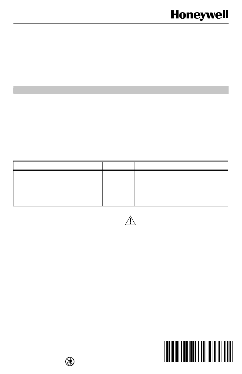
Location
Locate the W8735B in the equipment room near the
HVAC equipment and where access to the main
telephone line is available. See Fig.1.
™
Network, a
® U.S. Registered Trademark
Copyright © 2000 Honeywell • •All Rights Reserved
Place Bar Code Here
69- 1352
Page 2
T ELEPHONE ACCES S MODULE
FURNACE OR BOILER
WATER HEATER
Fig. 1. Locating W8735B in equi pm ent room.
W8735B
M14800
Position the subbase on the wall. Level the
6.
W8735B for appearance only; the device functions
properly even when not level. Use a pencil to mark
the position of the mounting holes on the wall.
NOTE: The wiring for the W8735B can be fed through
the back of the subbase or through the knock-
b
a
t
t
e
r
y
a
u
x
i
l
i
a
r
y
i
n
p
u
t
outs at the top and bottom of the subbase. If
using the knockouts, skip steps 7 and 8 and
proceed to step 9.
Mark the center of one or both wiring holes located
7.
in the back of the subbase.
Drill a 5/8 or 3/4 in. hole, where marked, for insert-
8.
ing the wires.
Remove the W8735B from the wall and drill 3/16
9.
in. holes in the wall (if drywall) where marked. For
firmer materials such as plaster or wood, drill 7/32
in. holes. Gently tap the anchors, provided, into the
holes until flush with the wall.
Reposition the W8735B over the holes.
10.
Loosely insert the screws into the holes and tighten
11.
the screws.
Mounting W8735B Telephone Access Module
CAUTION
Equipment Mounting Damage Hazard.
Can damage W8735B when mounted i nsi de
HVAC equipment.
Mount W8735B outside of any HVAC equipment,
where access to main telephone line is available.
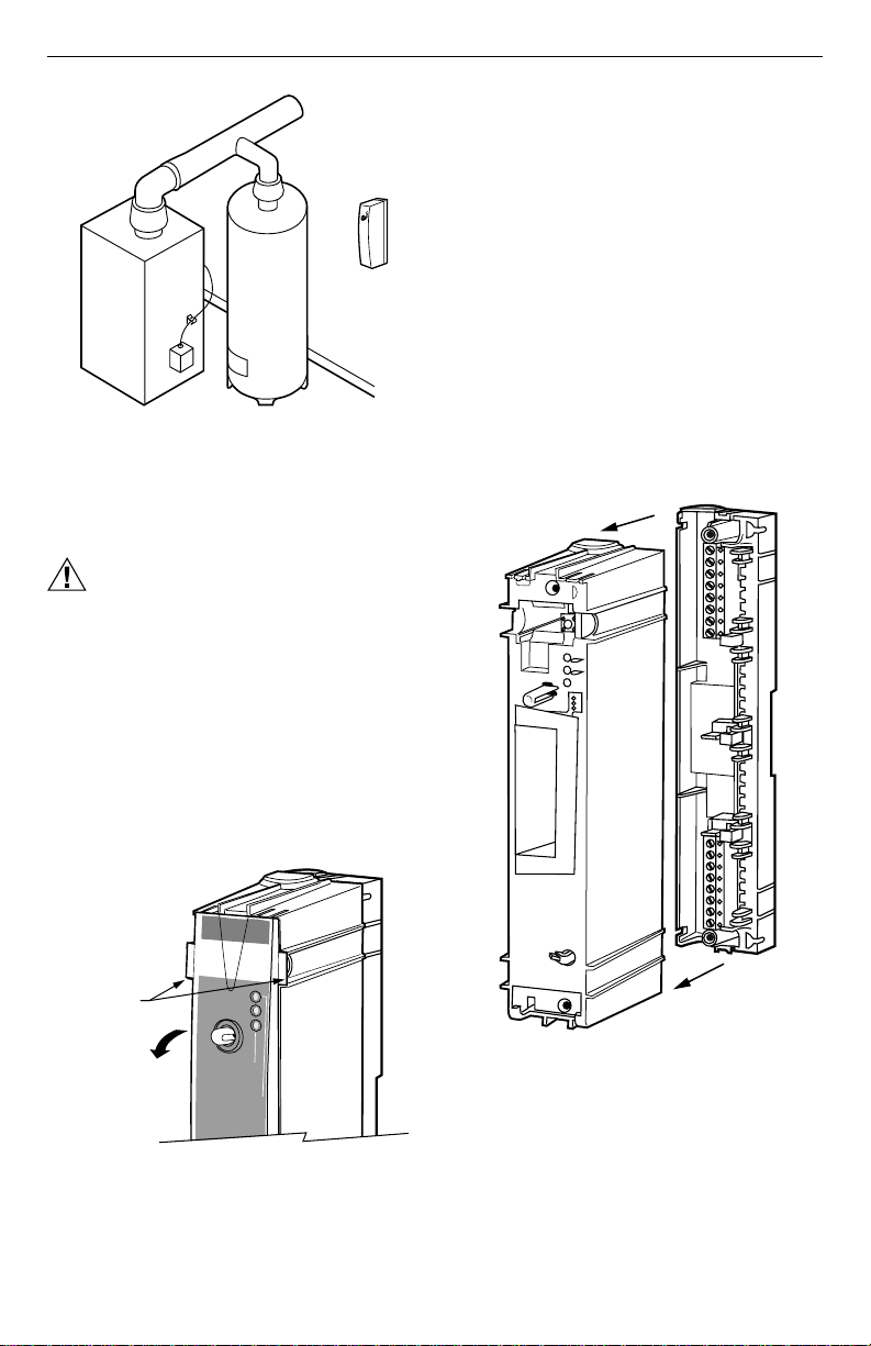
Unsnap the front cover from the W8735B by grasp-
1.
ing the tabs near the top of the module. See Fig. 2.
Swing the front cover down and lift it slightly to dis-
2.
engage the hinges.
Remove the cover and set aside.
3.
Remove the subbase by slowly pulling the subbase
4.
from the module housing. See Fig. 3
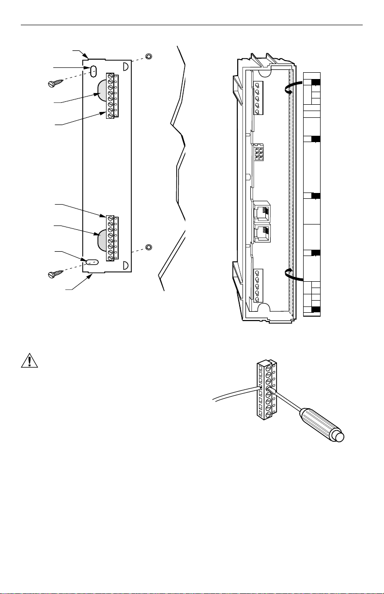
Locate the two mounting holes on the subbase.
5.
See Fig 4.
b
a
tte
FRONT COVER TABS
GRASP TABS AND
SWING COVER DOWN
ry
a
u
x
ilia
ry
in
p
u
t
o
n
momentary flash - ok
steady flash - replace
on continuously - replace
lin
e
.
SUBBASE
MODULE
M14802
Fig. 3. Removing subbase from m odule housing.
M14801
Fig. 2. Removing front cover.
69-1352 2
Page 3
TELEPHONE ACCESS MODULE
A
con.
1
2
3
Aux1
Aux2
B
con.
C
con.
D
con.
Line
in
Phone
out
M14778
Line in
Phone out
Ph1
Ph2
Ln1
Ln2
WIRING LABEL
ON INSIDE
OF MODULE
MODULE
WIRING
KNOCKOUT
MOUNTING
HOLE FOR
SUBBASE
MOUNTING
SCREWS (2)
WIRING
HOLE
WIRING
TERMINAL
BLOCK
WIRING
TERMINAL
BLOCK
WIRING
HOLE
MOUNTING
HOLE FOR
SUBBASE
WIRING
KNOCKOUT
Fig. 4. Mounting W8735B subba se.
WIRING
CAUTION
Electrical Shock Hazard.
Can cause personal injury and equipment
damage.
Disconnect power before beginning installation.
Locate the wiring label inside the telephone access
1.
module. See Fig. 5.
Loosen the terminal screws on the W8735B and
2.
connect the system wires. See Fig. 6 through 9
and Table 2.
Securely tighten each terminal screw.
3.
SUBBASE
WALL
WALL
ANCHORS
(2)
M14779
Fig. 5. Locating the wiring label ins ide the module.
TERMINAL BLOCK
WIRE
SCREW
DRIVER
M14803
Fig. 6. Connecting wires to terminals.
Wiring the Communications Bus
Connect terminals 1, 2, and 3 from the Telephone Access
Module to the other network devices. See Fig. 7.
Wiring the Auxiliary Input
Connect Aux1 and Aux2 terminals to an opt ional
normally open sensor contact, not included; see Fig. 7.
3 69-1352
Page 4

T ELEPHONE ACCES S MODULE
Wire the house telephones to the Phone out con-
Wiring the Telephone
CAUTION
Incorrect Telephone Line Hookup Hazard.
Inability to call out can result in personal
injury or property damage.
Improper installation can r esult in blocked
phone lines and inability to mak e 911 and
other emergency-report i ng phone calls.
Always connect the Telephone Access Module
first in line. When a monitored security system is
installed, connect the Telephone Access Module
second in line.
Observing this practice ensures that Telephone
Access Module drops off the line to allow priority
to the house telephone.
Wire the telephone line from the telephone com-
1.
pany to the Line in connections on the Telephone
Access Module.
IMPORTANT:
Wiring the Telephone Access Module first in line
(or second in line with a monitored security system) ensures that when any house telephone is
used (such as for an emergency), the Telephone Access Module drops off the line and
gives control priority to the house telephone.
Table 2. Terminal Designations.
W8735B Terminal Designations Function
1 To EnviraCom network terminal 1 (data).
2 To EnviraCom network terminal 2 (24 Vac).
3 To EnviraCom network terminal 3 (24 Vac).
Aux1 Auxiliary Input – Connect to N.O. sensor contact.
Aux2 Auxiliary Input – Connect to N.O. sensor contact.
a
Line in
Phone out
Ln1 Line in - Connect to telephone line.
Ln2 Line in - Connect to telephone line.
Ph1 Phone out - Connect to home telephones.
Ph2 Phone out - Connect to home telephones.
b
RJ11 connector – Connect to telephone line.
RJ11 connector – Connect to home telephones
2.
nections (see Table 2) on the Telephone Access
Module.
After the Telephone Access Module installation is
3.
complete, be sure to verify that the emergency
telephone line disconnect is operating corre ctl y.
a. Call the Telephone Access Module using an
outside line (installers use a cell phone).
b. While calling into the Telephone Access Mod-
ule, pick up a house telephone receiver. If you
get a dial tone after a few seconds and the
T e lephone Access Module drops control of the
line, the Telephone Access Module is installed
correctly.
c. If you do not get a dial tone on the hou se tele-
phone, follow the wiring diagrams and rewire
the telephone connections. See Fig. 8 and 9.
IMPORTANT:
Do not le ave t he i ns tall ati on u nti l th e em erge ncy
telephone line disconnect is operating correctly.
a
Connect to
b
Connect to
Line in or use terminals Ln1 and Ln2.
either
Phone out or use terminals Ph1 and Ph2.
either
Wiring Diagrams
See Fig. 7 through 9 for wiring diagrams.
69-1352 4
Page 5

TELEPHONE ACCESS MODULE
SUBBASE
Aux1
Aux2
Ph1
Ph2
Ln1
Ln2
L2
L1
(HOT)
SYSTEM
FACTORY
INSTALLER
JUMPERS
C7089B
OUTDOOR
TEMPERATURE
SENSOR
1
2
3
NOT
USED
N.O.
CONTACT
(OPTIONAL)
TRANSFORMER
NOT
USED
W8635A
T8635L
OT
1
2
3
C
R
R
H
R
C
2
1
OT
3
FAN
RELAY
HEAT 1
G
W1
W2
Y1
Y2
RELAY
HEAT 2
RELAY
COOL 1
RELAY
COOL 2
RELAY
M14774
Fig. 7. Wiring the communications bus and auxiliary input.
SUBBASEMODULE
TO
TELEPHONE
LINE
LINE
IN
PHONE
OUT
USE EITHER RJ11 TELEPHONE CONNECTORS OR
1
OPTIONAL TELEPHONE CONNECTIONS.
RJ11
RJ11
1
TO HOUSE
TELEPHONES
OPTIONAL
TELEPHONE
CONNECTIONS
TO HOUSE
TELEPHONES
TO
TELEPHONE
LINE
Fig. 8. Telephone installation wiring.
5 69-1352
NOT
USED
1
Ph1
Ph2
Ln1
Ln2
M14804
Page 6

T ELEPHONE ACCES S MODULE
MODULE
LINE
1
IN
SUBBASE
Connect and insert 9 Vdc alkaline battery.
4.
NOTE: 9 Vdc alkaline battery is optional; however,
when the battery is installed in the W8735B, the
power outage alert option is available.
Replace the cover. See Fig. 11.
5.
Insert the module cover latch pin; see Fig 12.
6.
Apply power to the system.
7.
IMPORTANT
The Telephone Access Module does not answer
within the first 90 seconds after applying power
or anytime power is disconnected.
Do not attempt to dial in to the Telephone Access
8.
Module for the first 90 seconds after applying
power to allow the Telephone Access Module time
to generate its user menu.
PHONE
OUT
USE EITHER RJ11 TELEPHONE CONNECTORS OR OPTIONAL
1
TELEPHONE CONNECTIONS.
Fig. 9. Telephone installation wiring including
monitored security system.
TO HOUSE
TELEPHONES
1
SECURITY SYSTEM
PANEL
TO TELEPHONE LINE
NOT
USED
Ph 1
Ph 2
Ln 1
Ln 2
TO
SECURITY
SYSTEM
TELEPHONE
OUT
M14805
Installing W8735B Module Housing Onto Subbase
After subbase is mounted and wiring complete, install the
module housing onto the subbase:
Align the subbase and the module housing an d
1.
press together; see Fig. 10.
Insert the 2 ¾ in. screws (provided) into the holes.
2.
Tighten screws; be careful not to over tighten.
3.
MODULE
2-3/4 IN. (70)
SCREW (2)
BATTERY
CONNECTOR
BATTERY
Fig. 10. Installing module on to subbase.
SUBBASE
M14769
69-1352 6
Page 7

SWING UP
TO LATCH
COVER
COMMUNICATION LED
PASS CODE
RESET BUTTON
STATUS LEDs
BATTERY
HOOK IN BOTTOM
TELEPHONE ACCESS MODULE
M14770
Fig. 11. Replacing module cover.
7 69-1352
Page 8

T ELEPHONE ACCES S MODULE
battery
auxiliary input
on line
momentary flash - ok
steady flash - replace
on continuously - replace
T o enter the configuration menu, see Table 3, call into the
T elephone Access Module using an outside line (typically
an installer would use a cellular telephone) :
Enter the default four-digit pass code of 1 2 3 4 fol-
1.
lowed by the # key on the telephone.
Enter 99 to access the configuration menu.
2.
NOTE: Set up the Telephone Access Module ID num-
ber, pass code, zone ID names and other settings as described in steps 3 and 4. Use Table 4
when setting up Configuration No. 6 in the Configuration Menu (choosing Zone ID nam es) in
Table 3.
Enter the configuration number, see Table 3, fol-
3.
lowed by th e # key .
T o return to the configuration menu press the * key;
4.
to exit the configuration menu, press the * key
again.
Telephone
Access
Module
www.honeyell.com/yourhome/
on continuously - replace
W
8735B
Fig. 12. Inserting module cover latch pin.
Installer Setup
IMPORTANT
Discuss with the homeowner if you, the HVAC
contractor, are providing a monitoring service.
When you have agreed, install telephone number setting three according to Configuration No.
9 setting in Table 3.
M14771
Ta ble 3. Configuration Menu .
Checkout
Call into the Telephone Access Module using any
1.
outside line (typically an installer would use a cellular telephone).
Enter the pass code.
2.
Use the Telephone Access Module User Menu to:
3.
a. Change the system mode.
b. Raise and lower the temperature.
c. Verify that the changes are made at the ther-
mostat.
d. If zoning is installed, repeat steps a. through c.
for each zone.
IMPORTANT
Be sure to explain the dialout alert messages
and possible causes (Table 5) to the homeowner.
e. Review the Owner’s Guide with the home-
owner and leave all the literature with them.
Configuration No. Description Settings
1 Identification (ID) Number.
2 Low Limit Setting.
3 High Limit Setting.
4 Ring Setting.
When the W8735B dials out, it uses this number to
identify who is calling. (This number can be used
to reference a data base of customers when
setting up a monitoring application.) The ID must
be programmed for the dial-out fu nction.
When the temperature at the thermostat is less
than this setting, the W8735B initiates a dial- out
call. If more than one thermostat is used in a
system, it uses the lowest value.
When the temperature at the thermostat is greater
than this setting, the W8735B initiates a dial- out
call. When more than one thermostat is used in a
system, it uses the highest value.
This setting determines how many rings occur
before the W8735B picks up the line.
Any combination of digits up to 25 digits in
length. This number is typically set to the
telephone number where the W8735B is
installed, such as the homeowner’s home
telephone number.
°
40
F(4°C) to 65°F (18°C) in 1°F (1°C)
increments. The factory default setting is
°
50
F (10°C).
°
70
F (21° C) to 110°F(43°C) in 1 °F (1°C)
increments. Factory default setting is 100
°
F (38°C).
1, 2, 3, 4, 5, 6, 7, 8, 9, 10. (Factory default
is two rings.)
69-1352 8
Page 9

TELEPHONE ACCESS MODULE
Table 3. Configuration Menu. (Continued)
Configuration No. Description Settings
5 Pass Code.
6 Zone ID Names (if zoning installed).
7 Filter Change Setting (enable/disable).
8 Dial-out Alert Setting (enable/di sable).
9 Dial-out Telephone Number Settings.
10 Power Outage Setting,
11 Software Version Number.
a
The W8735B prompts for setting the dial-out telephone number type as data or voice; choose voice because data is
reserved for future applications.
This setting provides secure access for the
homeowner’s comfort settings. (Installer: Have the
homeowner enter this setting either at the time of
installation or at their convenience.)
When more than one thermostat is installed in a
system, a name can be assigned to each zone
thermostat.
The W8735B can initiate a dial-out alert when the
HVAC equipment filter needs replacing. (If not
desired, set the value to disable.)
The W8735B can dial out on an alert condition .
See Table 5. (If not desired, set the value to
disable.)
W8735B can store up to three telephone numbers
a
to dial out
•
•
•
IMPORTANT
The W8735B can monitor if the power is
interrupted (when a 9 Vdc alkaline batter y is
installed). When power is interrupted continuously
for longer or equal to the power outage setting, the
W8735B initiates a dial-out alert.
Identifies version of software in Telephone Access
Module.
:
T elephone number setting one: The
homeowner selects a number where they can
be contacted when away from home (such as
office, second home, or cellular phone
number).
T elephone number setting two: An alternate
contact when the homeowner cannot be
reached (such as relative, friend or neighbo r).
T elephone number setting three (HVAC
contractor is providing monitoring service at
homeowner’s request): The HVAC contractor
phone number.
If these numbers are not programmed, a
dial-out is not initi ated on aler t . T elephone setting numbers one and two are
for the homeowner.
Any combination of four digits.
(Default pass code is 1234.)
Choose from a list of 26 zone names. (See
Table 4.)
Enable or disable. (Enable is the default. )
Enable or disable. (Enable is the default. )
Up to three telephone numbers can be
programmed. (Each telephone num ber
can be any combination of 25 digits.)
1, 2, 3 or 4 hours. (Factory default is 1
hour.)
None
9 69-1352
Page 10

T ELEPHONE ACCES S MODULE
Table 4. Zone IDs.
Zone ID
No. Zone Name
1 Basement
2 Bathroom
3 Bedroom
4Den
5 Dining Room
6Foyer
7 Game Room
8Great Room
9 Guest Room
10 Gym
11 Kid’s Bedroom
12 Kitchen
13 Library
14 Lower Level
15 Master Bedroom
16 Media Room
17 Nursery
18 Office
19 Pool Room
20 Porch
21 Spa
22 Sunroom
23 Theater
24 Upper Level
25 Wine Cella r
26 Workshop
Receiving and Acknowledging an Alert Message
The W8735B dials out until someone answering the
telephone (at the dial-out telephone number setting
locations described in Configuration No. 9 in Table 3)
acknowledges the alert message.
The message is acknowledged by pressing 1 on the
telephone keypad. If there is no acknowledgement, the
W8735B continues to dial the first two telephone
numbers in sequence every 30 minutes until an
acknowledgement is received.
The third telephone number setting is designed to enable
the HVAC contractor to provide a monitoring service at
the homeowner’s request. If a telephone number was
programmed into the third telephone location, the
W8735B also dials the third number and continues unt il
the HVAC contractor acknowledges the alert.
NOTE: The W8735B considers telephone numbe r set-
tings one and two independently from telephone
number setting three. Even when the recipient
at telephone number setting one or two
acknowledges the alert, it dials out and attempts
to receive an acknowledgement from the recipi ent at telephone number three, and vice-versa.
When the homeowner dials in and is informed that an
alert is active, the alert can be acknowledged
immediately to stop the calls to telephone numbers
settings one and two but not to telephone number setting
three.
IMPORTANT
Only the HVAC contractor can acknowledge the
alert dialed to telephone number settin g three.
The HVAC contractor dials in to cancel the active alert
messages to telephone number setting three by:
• Calling the home,
• Entering the last five digits of the teleph one num ber
setting three as the pass code; for example, if the
telephone number is 555-1234, ente ring 5 1 2 3 4 as
the pass code, and
• Following the menu to clear the alerts . (Using this
pass code allows only the HVAC dealer to cancel the
dial-out alert messages to telephone number setting
three.)
Sending an Alert Message
The W8735B can initiate a dial-out sequence from the
conditions in Table 5.
69-1352 10
Page 11

TELEPHONE ACCESS MODULE
Table 5. Dial-out Sequence Conditions.
Alert Messages Possible Causes
High Temperature The room temperature exceeded the high limit temperature setting
Low Temperature The room temperature exceeded the low limit temperature setting programmed
Heat Pump
Heating System
Cooling System
Auxiliary Input
a
b
b
c
Filter Change The thermostat is indicating a filter change is requi r ed for th e heating/cooling
programmed in the W8735B.
in the W8735B.
A heat pump compressor fault occurred.
The system heat output is below the acceptable performance; possible heating
system failure.
The system cool output is below the acceptable performance; possible cooling
system failure.
The auxiliary sensor connected to the auxiliary inp ut ter minal s has tripped.
system.
Power Outage A power outage exceeded the maximum allowable time.
a
When a W8635B Equipment Interface Module is install ed and L terminal is correctly used.
b
W7835A Discharge Temperature Sensor is required.
c
Normally open (N.O.) sensor contact is required. Keep the wire length between sensor and W8735B as short as possi-
ble and ensure wire is not subjected to any electrical in terf er ence.
TROUBLESHOOTING GUIDE
*
Symptom Possible Cause Solution
Battery indicator is on continuously. Battery is either dead or not installed. Install or replace battery.
Battery indicator is flashing with a
steady on-off pulse.
Battery indicator appears to flash
momentarily every ten seconds.
Telephone Access Module does not
answer.
On line indicator is illuminated. Telephone module is in dial-in or dial--out
Auxiliary input indicator is illuminated. W8735B detected a contact closure on
W8735B indicates, “The system is not
responding.”
Password cannot access the Telephone
Access Module.
Battery is weak. Replace battery.
Battery is good. No action required.
Power is not connected or 90-second
•
delay is in effect.
Phone line is not connected.
•
T elephone line is out of order.
•
sequence.
auxiliary input terminals.
W8735B is not receiving information from
the thermostats.
Incorrect pass code entered. Press and hold the pass code
11 69-1352
Wait 90 seconds and try
•
again.
Connect telephone line.
•
Contact telephone company.
•
Wait for the call to end.
Determine cause of contact
closure. Remedy problem
according to contact
manufacturer instructions.
Make sure all connections
between communicating
devices are good.
reset switch for five seconds.
The pass code is reset to 1-2-3-
4. Retry with the default pass
code. See Fig. 11.
Page 12

T ELEPHONE ACCES S MODULE
Home and Building Control Home and Building Control
Honeywell Honeywell Limited-Honeywell Limitée
1985 Douglas Drive North 35 Dynamic Drive
Golden Valley, MN 55422 Scarborough, Ontario
69-1352 G.H. 10-00 www.honeywell.com
M1V 4Z9
Printed in U.S.A. on recycled
paper containing at least 10%
post-consumer paper fibers.
 Loading...