

Page 1
([FHO
:%')9$9&RQWUROOHUV
%()25(,167$//$7,21
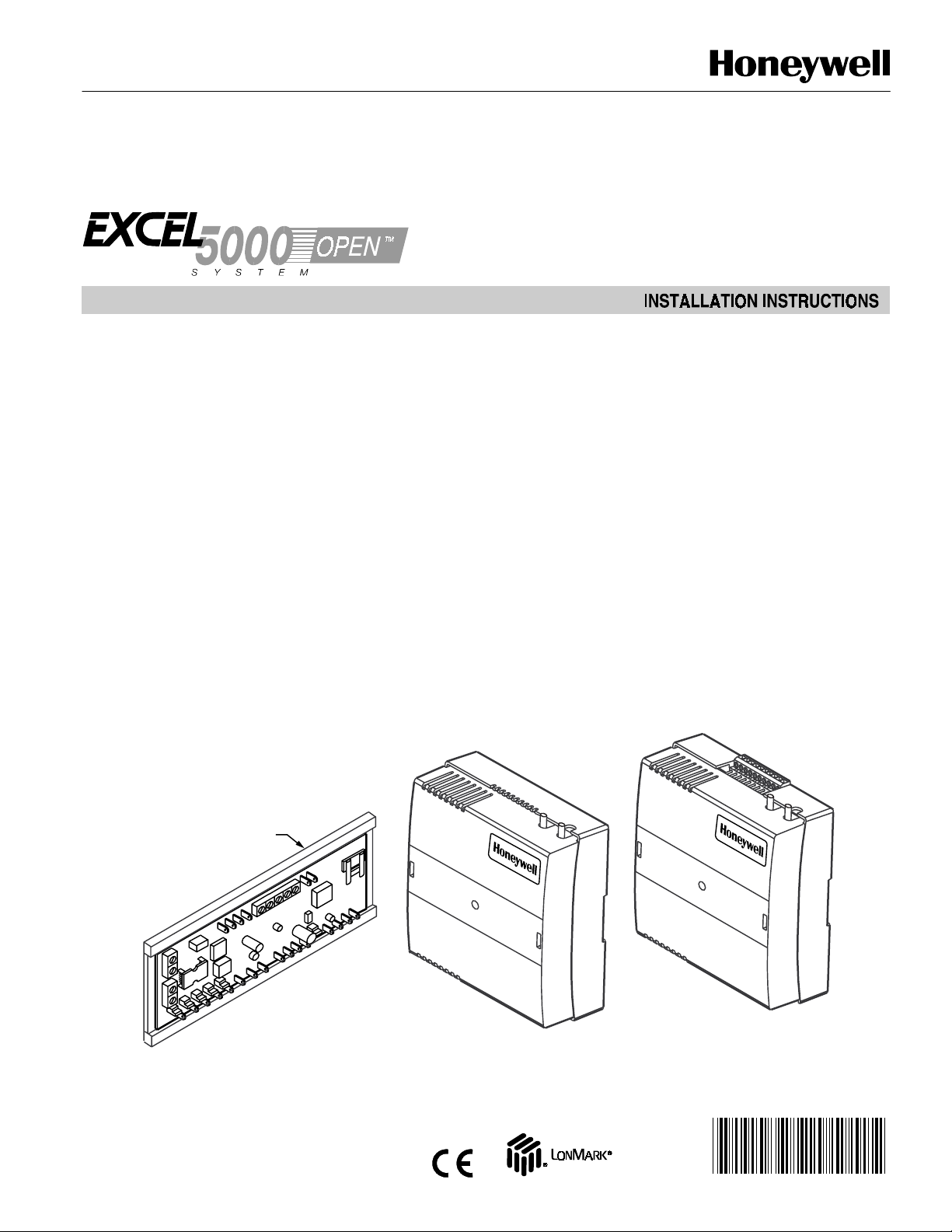
The Excel 10 VAV Controller is a Free Topology Transceiver
(FTT) LonMark compliant device that is available in three
versions: See Fig. 1.
1. W7751B—OEM Snaptrack-Mount, reference part
number 207912. Use a 3-1/4 inch by 9 inch (82 mm by
228 mm) section for each installation.
2. W7751D—Internally Wired Subbase mounts on a
standard four by four, a standard five by five conduit
box or on DIN Rail 1-3/8 by 9/32 (35 mm by 7.5 mm)
EN 50 022.
3. W7751F—Externally Wired Subbase, can be mounted
in a ring cabinet or on DIN Rail 1-3/8 by 9/32 (35 mm
by 7.5 mm) EN 50 022.
The models all contain a Microbridge air flow sensor and
communicate via the 78 Kilobaud Echelon LonWorks
E-Bus Network. They differ only in mounting and
terminations.
Any hardware that will be driven by the Triac outputs must
have a minimum current draw, when energized, of 25 mA at
20 Vac, a maximum of 500 mA at 30 Vac for the W7751B
and 1 A at 30 Vac for the W7751D,F.
,167$//$7,21
Mount the VAV controllers in locations that allow clearance
for wiring, servicing and module removal. (See Fig. 3 and 4
for mounting options used with the W7751D,F Subbase and
Fig. 5 for mounting dimensions.)
:%
The W7751B OEM model is implemented on a snaptrack
compatible printed wiring board (PWB). Terminal blocks are
used to make connections to the digital input terminals (13
through 17) the wall module terminals (19 through 25), and
the communications terminals 29 and 30. Connection for to
access the E-Bus is provided by plugging the connector into
the communications jack. Digital outputs, earth ground and
24 Vac power connections are made with quarter inch
(6.35 mm) quick connects.
Mount the VAV controller onto the snaptrack. Attach all
wiring to the appropriate quarter inch (6.35 mm) quick
connects and terminal blocks. See Wiring section.
3-1/4 IN. (82 MM)
SNAPTRACK
W7751B
U.S. Registered Trademark
Copyright 1997 Honeywell Inc. • All Rights Reserved
P1
P2
+
∆P
–
W7751D W7751F
M12605
95-7504
Page 2
EXCEL 10 W7751B,D,F VAV CONTROLLERS
:'
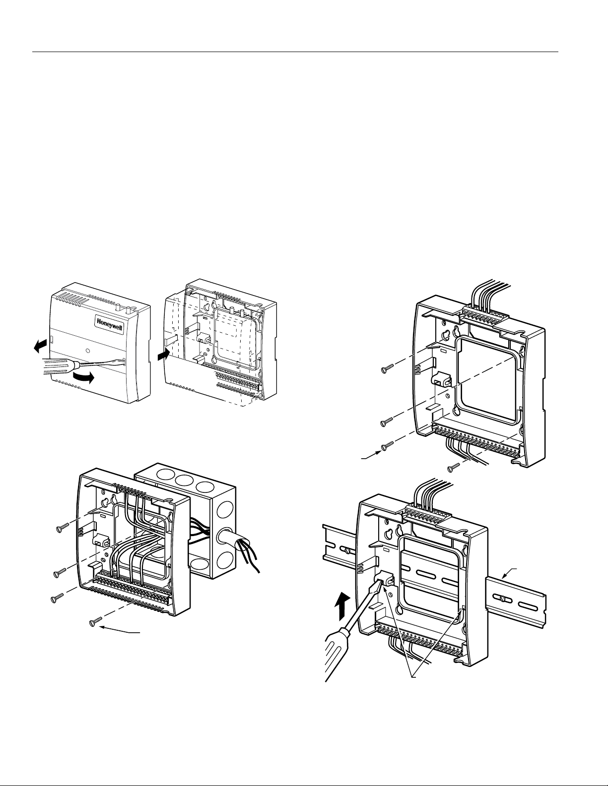
The W7751D uses a two-piece construction controller
module and an internally wired subbase. Remove the
controller module from the subbase (see Fig. 2). Field wiring
14 to 22 AWG (2.0 to 0.34 mm
into the four by four or five by five conduit box and is
connected to the terminal blocks on the subbase. When
wiring is complete, the controller module activates by
plugging into the subbase.
The internally wired subbase either mounts on a standard
4 inch by 4 inch electrical junction box or a standard 5 inch
by 5 inch electrical junction box using No. 6 (3.5 mm)
screws. See Fig. 3. Attach all wiring to the appropriate
terminal blocks on the subbase. See Wiring section. After
checking out all wiring, plug the controller module into the
subbase. Wiring checkout and troubleshooting can also be
performed with the controller module installed, by placing a
probe through the slots in the subbase.
2
) comes through a conduit
:)
The W7751F uses a two-piece construction controller
module and an externally wired subbase. Remove the
controller module from the subbase (see Fig. 2). This
subbase either mounts into a panel with screws or snaps
onto standard EN 50 022 DIN rail 35 mm by 7.5 mm
(1-3/8 in. by 5/16 in.). See Fig. 4. DIN rail is available through
local suppliers. Mount the subbase to the appropriate
surface. Type of screws (sheet metal, self-tapping or thread
forming) and length is determined by the type of mounting
material at the job site. Field wiring 14 to 22 AWG (2.0 to
0.34 mm
bottom external edges of the subbase. When wiring is
complete, the controller module activates by plugging into
the subbase.
Attach all wiring to the appropriate terminal blocks on the
externally wired subbase. See Wiring section. After checking
out all wiring, plug the controller module into the subbase.
2
) is connected to the terminal blocks on the top and
M8359
Fig. 2. W7751D,F controller module removal/replacement
(W7751D shown).
NO. 6 (3.5 MM) SCREW (4)
M8360
Fig. 3. W7751D Subbase four by four or five by five
conduit box mounting options (proper orientation is
vertical with terminals at top and bottom as shown).
NO. 6 (3.5 MM)
SCREW (4)
DIN RAIL RELEASES
DIN RAIL
M12602
95-7504 2
Fig. 4. W7751F Subbase wall and DIN rail mounting
options (proper orientation is vertical with terminals at
top and bottom as shown).
Page 3
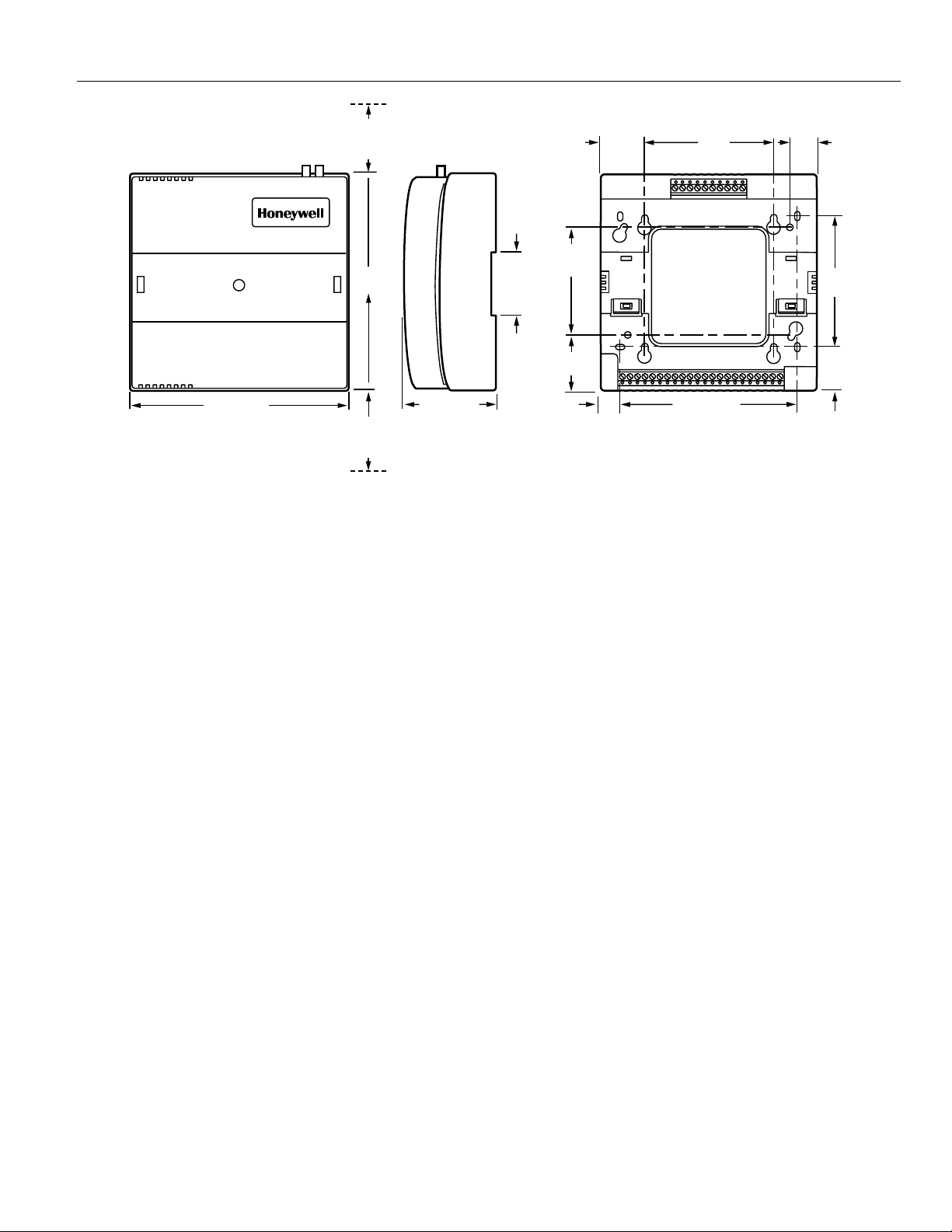
MAINTAIN A MINIMUM DISTANCE
OF 4 IN. (100 mm) FROM OTHER
DEVICES OR PANELS FOR
ATTACHING AIR FLOW TUBING.
5-21/32
(144)
1-3/8
(35)
DIN RAIL
MOUNTING
SLOT
EXCEL 10 W7751B,D,F VAV CONTROLLERS
3/4
(19)
3-7/16
5 X 5
MOUNTING
HOLES
1-3/32
(28)
4 X 4
MOUNTING
HOLES
(87)
5-21/32 (144)
MAINTAIN A MINIMUM DISTANCE
OF 3 IN. (76 mm) FROM OTHER
DEVICES OR PANELS FOR ACCESS
TO THE COMMUNICATIONS JACK.
2-11/32 (60)
Fig. 5. W7751D,F Subbase mounting dimensions (W7751D shown).
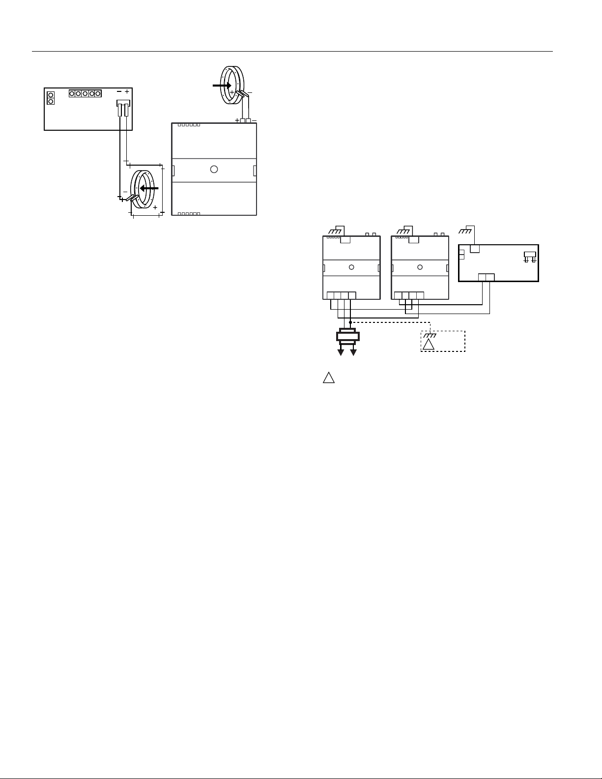
3LSLQJ
$LUIORZ3LFNXS
Connect the air flow pickup to the two connectors on the VAV
controller. See Fig. 6.
NOTES:
— Use 1/4 inch (6 mm) outside diameter with 0.040 in.
(1 mm) wall thickness plenum rated 1219 FR (94V-2)
tubing.
— Always use a fresh cut on the end of the tubing that
connects to the air flow pickups and the connectors on the
VAV controllers.
Connect the high pressure or upstream tube to the plastic
restrictor labeled (+) or P1 and the low pressure or
downstream tube to the restrictor labeled (-) or P2. See
labeling in Fig. 6.
NOTE: If controllers are mounted in unusually dusty or dirty
When twin tubing is used from the pickup, split the pickup
tubing a short length to accommodate the connections.
NOTES:
environments, a 5-micron disposable air filter is
recommended for the high pressure line (marked
as +) connected to the air flow pickup. This applies
to all controller models.
— The tubing from the air flow pickup to the VAV
controller should not exceed three feet
(0.914m). Any length greater than this will
degrade the flow sensing accuracy.
— Use caution when removing tubing from a VAV
connector. Always pull straight away from the
connector; never remove by pulling at an angle.
1-1/2
(38)
1/2
(13)
4-21/32 (118)
1-3/32
(28)
M12603
:LULQJ
All wiring must comply with applicable electrical codes and
ordinances or as specified on installation wiring diagrams.
NOTES:
— For multiple controllers operating from a single
transformer, the same side of the transformer secondary
must be connected to the same input terminal in each
controller and the ground terminals (28 on the W7751B,
and 32 on the W7751D,F) must be connected to a verified
earth ground for each controller in the group. See Fig. 7.
(Controller configurations will not necessarily be limited to
three devices, but the total power draw including
accessories can not exceed 100 VA when powered by the
same transformer (U.S. only). See System Engineering
form, 74-2949, for power wiring recommendations.)
— The following pairs of terminals are electrically equivalent
for 24 Vac power wiring:
W7751D,F terminals 1 and 3, 2 and 4.
— All loads on an Excel 10 controller must be powered by
the same transformer that powers the Excel 10 controller.
— Keep the earth ground connection (terminal 28 on the
W7751B, and terminal 32 on the W7751D,F) wire run as
short as possible. Refer to Fig. 11 and 17.
not
— Do
connect the Analog ground nor Digital ground
terminals (13, 16, 22 and 24 on the W7751B and 13, 18,
26, 28 and 31 on the W7751D,F) to earth ground. Refer to
Fig. 11 and 17.
3 95-7504
Page 4
EXCEL 10 W7751B,D,F VAV CONTROLLERS
AIR FLOW
PICKUP
P2
P1
HI
LOW
M12604
W7751B
AIR FLOW
PICKUP
W7751D,F
Fig. 6. VAV air flow pickup connections.
3RZHU
The 24 Vac power from an energy limited Class II Power
Source must be provided to each VAV controller. To conform
to Class II restrictions, transformers must not be larger than
100 VA (U.S. only). A transformer that meets CE mark
requirements and that meets the Low Voltage Directive
(LVD) requirements must be used in Europe for all
installations of this product.
IMPORTANT
Power must be off prior to connecting to or
removing connections from terminals 9 and 10 on
the W7751B and terminals 1 and 2 or 3 and 4 on
the W7751D,F.
Use the heaviest gauge wire available, up to 14 AWG
(2.0 mm
2
) with a minimum of 18 AWG (1.0 mm2) for all
power and earth ground wiring. For nonplenum, open areas,
run cables exposed (or in conduit if required).
See the following
IMPORTANT
Equipment (UL 1995, U.S. only)
Heating and Cooling
on
.
IMPORTANT
If the W7750 Controller is used on
Cooling Equipment (UL 1995, U.S. only)
Heating and
and the
transformer primary power is more than 150 volts,
connect the transformer secondary to earth ground,
see Fig. 7.
NOTES:
— Unswitched 24 Vac power wiring can be run in
the same conduit as the E-Bus cable.
— Maintain a three-inch (76 mm) separation
between Triac outputs and E-Bus wiring
throughout installation.
&RPPXQLFDWLRQV
Refer to
complete description of E-Bus network topology rules.
Approved cable types for E-Bus communications wiring are
Level IV 22 AWG (0.34 mm
unshielded, twisted pair, solid conductor wire. For
nonplenum areas, U.S. part AK3781 (one pair) or U.S. part
AK3782 (two pair) can be used. In plenum areas, U.S. part
E-Bus Wiring Guidelines form, 74-2865
2
) plenum or non-plenum rated
, for a
AK3791 (one pair) or U.S. part AK3792 (two pair) can be
used. Communications wiring can be run in a conduit, if
needed, with
non-switched
24 Vac or sensor wiring. If a
longer E-Bus network is required, a Q7740A 2-way or
Q7740B 4-way repeater can be added to extend the length of
the E-Bus. A Q7751A Router can be added to partition the
system into two segments and effectively double the length
of the E-Bus. Only one router is allowed with each Excel 10
Zone Manager, and each network segment can have a
maximum of one repeater.
Pull the cable to each controller on the E-Bus and connect to
communication terminals 29 and 30 (W7751B), 19 and 20
(W7751D,F).
EARTH
GROUND
EARTH
GROUND
28
9
24V
10
W7751B
COM
M12606
EARTH
GROUND
W7751D,F
32
24V
COM
24V
COM
1234
24 VAC
120/240 VAC
IF THE W7751 CONTROLLER IS USED IN UL 1995 EQUIPMENT
1
AND THE PRIMARY POWER IS MORE THAN 150 VOLTS,
GROUND ONE SIDE OF TRANSFORMER SECONDARY.
EARTH
GROUND
1
TRANSFORMER
32
24V
COM
234
W7751D,F
24V
COM
1
Fig. 7. Power wiring for multiple controllers.
Notes on Communications Wiring:
• All field wiring must conform to local codes and
ordinances (or as specified on the installation drawings).
• Approved cable types for E-Bus communications wiring
are Level IV 22 AWG (0.34 mm
2
) plenum or non-plenum
rated unshielded, twisted pair, solid conductor wire. For
nonplenum areas, U.S. part AK3781 (one pair) or U.S.
part AK3782 (two pair) can be used. In plenum areas,
U.S. part AK3791 (one pair) or U.S. part AK3792 (two
pair) can be used. See Table 11 for part numbers in
System Engineering form, 74-2949.
• Unswitched 24 Vac power wiring can be run in the same
conduit as the E-Bus cable.
• Do not bundle output wires with sensor, digital input or
communications E-Bus wires.
• Do not use different wire types or gauges on the same
E-Bus segment. The step change in line impedance
characteristics would cause unpredictable reflections on
the E-Bus. When using different types is unavoidable, use
a Q7751A Router at the junction.
• In noisy (high EMI) environments, avoid wire runs parallel
to noisy power cables, motor control centers, or lines
containing lighting dimmer switches, and keep at least
3 in. (76 mm) of separation between noisy lines and the
E-Bus cable.
• Make sure that neither of the E-Bus wires is grounded.
95-7504 4
Page 5

EXCEL 10 W7751B,D,F VAV CONTROLLERS
NOTE: If a 209541B Termination Module is required at the
VAV controller, connect two of the three termination
module wires to the E-Bus terminals. Selecting the
appropriate two wires depends on the E-Bus
network topology. Refer to the
Guidelines
form, 74-2865, and the
Termination Module Installation Instructions,
E-Bus Wiring
Excel 10 FTT
form
95-7554. For example, using a doubly terminated
daisy-chained bus topology, if controllers are on
either end of an E-Bus wire run, mount the
termination module on the appropriate terminals as
shown in Fig. 8.
PART
NUMBER
209541B
MODULE
W7751B
M12607
E-BUS
19
20
BROWN
ORANGE
W7751D,F
PART
NUMBER
209541B
TERMINATION
MODULE
29
30
E-BUS
19
20
BROWN
ORANGE
TERMINATION
W7751D,F
111TO ASSURE PROPER ELECTRICAL CONTACT, WIRES MUST BE TWISTED
TOGETHER BEFORE INSERTION INTO THE TERMINAL BLOCK.
Fig. 8. Termination modules (place a wire nut on
each remaining wire that is not connected to a
controller or device).
Wire to the terminal blocks as follows:
1.
Strip 3/16 in. (5 mm) insulation from the conductor.
2.
Insert the wire in the required terminal location and
tighten the screw to complete the termination.
3.
If two or more wires are being inserted into one
terminal location, first strip the wires to 1/2 in. (13 mm),
then twist the wires together and cut to 3/16 in. (5 mm)
before inserting them.
IMPORTANT
Screw type terminal blocks on the W7751D,F are
designed to accept no more than one 14 AWG
(2.0 mm
AWG (2.0 mm
2
) conductor. Multiple wires that are 14
2
) can be connected with a wire nut.
Include a pigtail with this wire group and attach the
pigtail to the individual terminal block.
NOTE: When two or more wires are to be attached to the
same terminal, other than 14 AWG (2.0 mm
2
), be
sure to twist them together. Deviation from this rule
can result in improper electrical contact. See Fig. 9.
Wire to quarter inch quick connects as follows:
1.
Strip 3/16 in. (5 mm) insulation from the conductor(s).
2.
Select appropriate size quarter-inch (6.35 mm) quick
connect that will accept the number of wire(s) needed
for terminal.
3.
Crimp the quarter-inch (6.35 mm) quick connect and
attach it to the appropriate terminal location.
:LULQJ'HWDLOV
Fig. 11 and 17 illustrate the terminal arrangement on the
W7751B and W7751D,F Controllers. Fig. 11 through 16
provide detailed wiring diagrams for the W7751B Controller,
and Fig. 17 through 22 provide detailed wiring diagrams for
the W7751D,F Controllers. Refer to job drawings for specific
installation wiring diagrams.
The W7751B VAV Controller must have two complete loops
of the wires coming from the T7770 Wall Modules that pass
through the split ferrite cores (Fair-Rite 044316451 or
equivalent Honeywell part 229997CB). The W7751B VAV
Controller and the split ferrite cores must also be in a metal
enclosure to ensure compliance with CE requirements. See
Fig. 10.
1/2
(13)
STRIP 1/2 IN. (13 MM)
1. 2. TWIST WIRES
FROM WIRES TO
BE ATTACHED AT
ONE TERMINAL.
TOGETHER WITH
PLIERS (A MINIMUM
OF THREE TURNS).
Fig. 9. Attaching two or more wires at terminal blocks.
TWO 14 AWG
2
) WIRES
(2.0 MM
W7751D,F
3. CUT TWISTED END OF WIRES TO 3/16 IN. (5 MM)
BEFORE INSERTING INTO TERMINAL AND TIGHTENING
SCREW. THEN PULL ON EACH WIRE IN ALL TERMINALS
TO CHECK FOR GOOD MECHANICAL CONNECTION.
W7751B
M12608
5 95-7504
Page 6

EXCEL 10 W7751B,D,F VAV CONTROLLERS
1.
WIRES TO T7770
WALL MODULE
WIRES TO W7751B
CONTROLLER
2.
WIRES TO T7770
WALL MODULE
WIRES TO W7751B
CONTROLLER
M12609
Fig. 10. Ferrite core for T7770 Wall Module wires going to
a W7751B VAV Controller.
7 6985432
LED
T7770C
WALL
MODULE
29
30
E-BUS
2
TRIAC
OUTPUTS
JACK FOR
E-BUS
NETWORK
ACCESS
CW COM CCW
ML6161 DAMPER
ACTUATOR
1
GND
E-BUS
SET PT
BYPASS
1
GROUND
NETWORK
COMMUNIC ATIONS
123 45678
DAMPER OPEN
E-BUS
SENSOR
E-BUS
NETWORK
ACCESS
EARTH
28 25 24 23
EGND
W7751B VAV
CONTROLLER BOARD
TRIAC EQUIVALENT CIRCUIT
DO 2
DO 4
DO 1
DO 3
DO 5
DAMPER CLOSE
REHEAT STAGE 3
SERIES OR PARALLEL FAN
REHEAT STAGE 1 (OR OPEN)
REHEAT STAGE 2 (OR CLOSE)
REHEAT
STAGE
CONTACTORS
JACK
FOR
22
21
AI 1
AI 2
AGND
AGND
WALL MODULE
DO 6
DO 8
DO 7
+24 VAC
9
3
24 VAC
TO OTHER
CONTROLLERS
SERIES OR
PARALLEL FAN
CONTACTORS
AIR FLOW
∆P PICKUP
1920
MICROBRIDGE
LED
BYPASS
SENSOR
COM
DGND
–24 VAC
13 14 15 16
10
24
VAC
4
OCCUPANCY
SENSOR
(CONTACT
CLOSED =
OCCUPIED)
LOAD POWER
∆P SENSOR
DGND
DI 2
DI 1
17
WINDOW
CONTACT
(CONTACT
CLOSED =
WINDOW
CLOSED)
DI 3
4
1
EARTH GROUND WIRE LENGTH SHOULD BE HELD TO A MINIMUM.
USE THE HEAVIEST GAUGE WIRE AVAILABLE, UP TO 14 AWG (2.O MM2)
WITH A MINIMUM OF 18 AWG (1.O MM2), FOR EARTH GROUND WIRE.
TO ASSURE PROPER ELECTRICAL CONTACT, WIRES MUST BE TWISTED
2
TOGETHER BEFORE INSERTION INTO THE TERMINAL BLOCK.
3
LOAD POWER WIRE CAN BE CONNECTED TO TERMINAL 9.
CONTACTS MUST BE SUITABLE FOR DRY SWITCHING, 5V AT 10 mA. USE
4
SEALED TYPE, GOLD FLASHED OR PIMPLED CONTACTS.
M12610
Fig. 11. Typical W7751B application wiring diagram.
(For notes 2 and 3, refer to Fig. 9.)
95-7504 6
Page 7

C7770A
AIR FLOW
∆P PICKUP
1920
MICROBRIDGE
LED
BYPASS
COM
DGND
13 14 15 16 17
24
VAC
4
AIR
TEMPERATURE
SENSOR
∆P SENSOR
DGND
DI 2
DI 3
DI 1
4
WINDOW
CONTACT
(CONTACT
CLOSED =
WINDOW
CLOSED)
M12611
7 6985432
LED
BYPASS
T7770C
WALL
MODULE
1
29
30
E-BUS
2
NETWORK
COMMUNIC ATIONS
TRIAC
OUTPUTS
JACK FOR
E-BUS
NETWORK
ACCESS
CW COM CCW
ML6161 DAMPER
ACTUATOR
1
EARTH GROUND WIRE LENGTH SHOULD BE HELD TO A MINIMUM.
USE THE HEAVIEST GAUGE WIRE AVAILABLE, UP TO 14 AWG (2.O MM2)
WITH A MINIMUM OF 18 AWG (1.O MM2), FOR EARTH GROUND WIRE.
2
TO ASSURE PROPER ELECTRICAL CONTACT, WIRES MUST BE TWISTED
TOGETHER BEFORE INSERTION INTO THE TERMINAL BLOCK.
3
LOAD POWER WIRE CAN BE CONNECTED TO TERMINAL 9.
CONTACTS MUST BE SUITABLE FOR DRY SWITCHING, 5V AT 10 mA. USE
4
SEALED TYPE, GOLD FLASHED OR PIMPLED CONTACTS.
1
GND
E-BUS
SET PT
GROUND
123 45678
DAMPER OPEN
E-BUS
SENSOR
JACK
FOR
E-BUS
NETWORK
ACCESS
EARTH
28 25 24 23
AI 2
AGND
EGND
W7751B VAV
CONTROLLER BOARD
TRIAC EQUIVALENT CIRCUIT
DO 2
DO 4
DO 1
DO 3
DAMPER CLOSE
REHEAT STAGE 3
REHEAT STAGE 1 (OR OPEN)
REHEAT STAGE 2 (OR CLOSE)
REHEAT
STAGE
CONTACTORS
WALL MODULE
DO 6
DO 5
DO 7
3
24 VAC
TO OTHER
CONTROLLERS
SERIES OR PARALLEL FAN
SERIES OR
PARALLEL FAN
CONTACTOR
22
AI 1
DO 8
AGND
21
SENSOR
+24 VAC
–24 VAC
9
10
OCCUPANCY
SENSOR
(CONTACT
CLOSED =
LOAD POWER
OCCUPIED)
Fig. 12. Typical W7751B application wiring diagram
using the T7770C Wall Module and a C7770A Air
Temperature Sensor. (For notes 2 and 3, refer to Fig. 9.)
EXCEL 10 W7751B,D,F VAV CONTROLLERS
7 6985432
LED
BYPASS
T7770C
WALL
MODULE
1
29
30
E-BUS
2
COMMUNIC ATIONS
TRIAC
OUTPUTS
JACK FOR E-BUS
NETWORK ACCESS
SIGNAL
STEM
UP
M6410 SERIES 60
VALVE ACTUATOR
TWO OR
THREE-WAY VALVE
1
2
3
4
STEM
COM
DOWN
EARTH GROUND WIRE LENGTH SHOULD BE HELD TO A MINIMUM.
USE THE HEAVIEST GAUGE WIRE AVAILABLE, UP TO 14 AWG (2.O MM2)
WITH A MINIMUM OF 18 AWG (1.O MM2), FOR EARTH GROUND WIRE.
TO ASSURE PROPER ELECTRICAL CONTACT, WIRES MUST BE TWISTED
TOGETHER BEFORE INSERTION INTO THE TERMINAL BLOCK.
LOAD POWER WIRE CAN BE CONNECTED TO TERMINAL 9.
CONTACTS MUST BE SUITABLE FOR DRY SWITCHING, 5V AT 10 mA. USE
SEALED TYPE, GOLD FLASHED OR PIMPLED CONTACTS.
Fig. 13. Typical W7751B modulating reheat valve and a
series/parallel fan wiring diagram. (For notes 2 and 3,
1
GND
E-BUS
E-BUS
SET PT
SENSOR
JACK
FOR
E-BUS
NETWORK
ACCESS
EARTH
GROUND
NETWORK
TRIAC EQUIVALENT CIRCUIT
DO 1
123 45678
OPEN
28 25 24 23
AI 2
AGND
EGND
DO 5
LINE
WALL MODULE
DO 6
DO 7
SERIES OR
PARALLEL
FAN
W7751B VAV
CONTROLLER BOARD
DO 2
DO 4
DO 3
CLOSED
SIGNAL
POWER
refer to Fig. 9.)
22
AI 1
DO 8
21
AGND
+24 VAC
9
3
∆P PICKUP
1920
LED
BYPASS
SENSOR
COM
–24 VAC
13 14 15 16 17
10
24
VAC
4
OCCUPANCY
SENSOR
(CONTACT
CLOSED =
OCCUPIED)
AIR FLOW
MICROBRIDGE
∆P SENSOR
DGND
DI 1
DGND
DI 2
WINDOW
CONTACT
(CONTACT
CLOSED =
WINDOW
CLOSED)
DI 3
4
M12612
7 95-7504
Page 8

EXCEL 10 W7751B,D,F VAV CONTROLLERS
7 6985432
LED
BYPASS
T7770C
WALL
MODULE
1
29
30
E-BUS
2
TRIAC
OUTPUTS
JACK FOR E-BUS
NETWORK ACCESS
LINE
POWER
1
EARTH GROUND WIRE LENGTH SHOULD BE HELD TO A MINIMUM.
USE THE HEAVIEST GAUGE WIRE AVAILABLE, UP TO 14 AWG (2.O MM2)
WITH A MINIMUM OF 18 AWG (1.O MM2), FOR EARTH GROUND WIRE.
2
TO ASSURE PROPER ELECTRICAL CONTACT, WIRES MUST BE TWISTED
TOGETHER BEFORE INSERTION INTO THE TERMINAL BLOCK.
3
LOAD POWER WIRE CAN BE CONNECTED TO TERMINAL 9.
CONTACTS MUST BE SUITABLE FOR DRY SWITCHING, 5V AT 10 mA. USE
4
SEALED TYPE, GOLD FLASHED OR PIMPLED CONTACTS.
NETWORK
COMMUNIC ATIONS
STAGE 1
1
GND
E-BUS
SET PT
GROUND
123 45678
E-BUS
SENSOR
JACK
FOR
E-BUS
NETWORK
ACCESS
EARTH
28 25 24 23
AI 2
AGND
EGND
DO 5
DO 6
WALL MODULE
DO 7
CONTACTORS
24 VAC ONLY
STAGE 3
W7751B VAV
CONTROLLER BOARD
TRIAC EQUIVALENT CIRCUIT
DO 2
DO 4
DO 1
DO 3
STAGE 2
22
AI 1
DO 8
21
AGND
+24 VAC
9
3
∆P PICKUP
1920
LED
BYPASS
SENSOR
COM
–24 VAC
13 14 15 16 17
10
24
VAC
4
OCCUPANCY
SENSOR
(CONTACT
CLOSED =
OCCUPIED)
AIR FLOW
MICROBRIDGE
∆P SENSOR
DGND
DI 1
DGND
DI 2
WINDOW
CONTACT
(CONTACT
CLOSED =
WINDOW
CLOSED)
DI 3
4
M12613
Fig. 14. Typical W7751B staged reheat wiring diagram.
(For notes 2 and 3, refer to Fig. 9.)
W7751B VAV
TRIAC
OUTPUTS
1
2
3
4
CONTROLLER BOARD
123 45678
OPEN
CLOSE
MMC325 PNEUMATIC
TRANSDUCER
24 (H)
24 (N)
24 (H)
24 (N)
INCREASE
DECREASE
2
REVERSE WIRES (INCREASE/DECREASE) TO REVERSE ACTION
(DIRECT/REVERSE).
MAKE SURE ALL TRANSFORMER/POWER WIRING IS AS SHOWN:
REVERSING TERMINATIONS WILL RESULT IN EQUIPMENT MALFUNCTION.
OPTIONAL 24 VAC WIRING TO NEXT CONTROLLER.
USE 1/4 IN (6 MM) PNEUMATIC TUBING. MINIMUM BRANCH LINE MUST BE
6 FT. (1.8M) OR LONGER.
3
1
– 24 VAC
+ 24 VAC
9
10
M
B
PNEUMATIC
COM
24
VAC
M
4
VALVE
M12614
Fig. 15. Typical W7751B pneumatic transducer wiring
diagram. (For notes 2 and 3, refer to Fig. 9.)
W7751B VAV
TRIAC
OUTPUTS
ON
OFF
CONFIGURATION
DIP SWITCHES
(LOCATED ADJACENT
TO THE INPUT
TERMINAL BLOCK)
CONTROLLER BOARD
123 45678
1234
3
ML7984B
2
ML7984B
COM
– 24 VAC
+ 24 VAC
9
10
1
24
VAC
24 (N)
24 (N)
2
PWM
(H 24 VAC)
PWM
(H 24 VAC)
VALVE ACTUATOR
PWM OUTPUT
FROM CNTRL
PERIPHERAL HEAT
VALVE ACTUATOR
PWM OUTPUT
FROM CNTRL
PWM VALVE ACTUATOR
24 (H)
T6 T5 C B W R
PWM VALVE ACTUATOR
24 (H)
T6 T5 C B W R
REHEAT
95-7504 8
1
MAKE SURE ALL TRANSFORMER/POWER WIRING IS AS SHOWN:
REVERSING TERMINATIONS WILL RESULT IN EQUIPMENT MALFUNCTION.
2
TO ASSURE PROPER ELECTRICAL CONTACT, WIRES MUST BE TWISTED
TOGETHER BEFORE INSERTION.
TURN POWER OFF BEFORE SETTING THE DIP SWITCHES.
3
M12615
Fig. 16. Typical W7751B PWM reheat and
PWM peripheral heat valve actuator wiring diagram.
(For notes 2 and 3, refer to Fig. 9.)
Page 9

EXCEL 10 W7751B,D,F VAV CONTROLLERS
NOTE: Make sure to set the Configuration DIP Switch as
shown in Fig. 16. Switches 1 through 3 set the
timing of the ML7984B valve actuator to match the
W7751B outputs (0.1 sec. Min. with a max. time of
25.6 sec.). Switch 4 determines the action of the
actuator (Off = Direct Acting, On = Reverse Acting).
4
WINDOW
CONTACT
(CONTACT
CLOSED =
WINDOW
CLOSED)
4
OCCUPANCY
SENSOR
(CONTACT
CLOSED =
OCCUPIED)
1
EARTH
GROUND
W7751D,F
SUBBASE
TRIAC EQUIVALENT CIRCUIT
3
24V
24V
COM
123456789101112 13 14 15 16 17 18 19 20 21
2
31 30 29 28 27 26 25
32
EARTH
GROUND
GROUND
DI-1(OCCUP)
OUT 3
OUT 2
OUT 4
OUT 1
COM
DI-2
AI-2 FOR
(WINDOW)
OUT 5
WALL MODULE
W7751 D&F
AI-1 SETPT
GROUND
OUT 6
OUT 7
OUT 8
AIR TEMPERATURE SENSOR
AIR FLOW
∆P PICKUP
24 23
BYPASS
SENSOR
GROUND
NOT
EARTH
NOT
USED
NOT
C7770A
7 6985432
LED
SET PT
BYPASS
SENSOR
T7770C
WALL
MODULE
E-BUS NETWORK
HI
LED
MICROBRIDGE
∆P SENSOR
COMMUNICATIONS
NETWORK
DI-3
GND
E-BUS
USED
1
GND
E-BUS
E-BUS
JACK FOR
ACCESS
LOW
NOT
USED
22
4
WINDOW
CONTACT
(CONTACT
CLOSED =
WINDOW
CLOSED)
4
OCCUPANCY
SENSOR
(CONTACT
CLOSED =
OCCUPIED)
1
EARTH
GROUND
W7751D,F
SUBBASE
TRIAC EQUIVALENT CIRCUIT
3
24V
24V
COM
123456789101112 13 14 15 16 17 18 19 20 21
5
STEM
UP
M6410 SERIES 60
VALVE ACTUATOR
2
31 30 29 28 27 26 25
32
EARTH
GROUND
GROUND
DI-1(OCCUP)
OUT 3
OUT 2
OUT 4
OUT 1
COM
OPEN SIGNAL
CLOSED SIGNAL
STEM
COM
DOWN
DI-2
(WINDOW)
OUT 5
WALL MODULE
AI-2 FOR
W7751 D&F
AI-1 SETPT
OUT 6
OUT 7
SENSOR
GROUND
NOT
EARTH
GROUND
NOT
OUT 8
T7770C
WALL
MODULE
AIR FLOW
∆P PICKUP
24 23
LED
BYPASS
COMMUNICATIONS
USED
NOT
USED
7 6985432
LED
SET PT
BYPASS
E-BUS NETWORK
HI
MICROBRIDGE
∆P SENSOR
NETWORK
DI-3
GND
GND
E-BUS
SENSOR
JACK FOR
ACCESS
LOW
E-BUS
NOT
1
E-BUS
USED
22
2
E-BUS
5
OPEN SIGNAL
DAMPER OPEN
DAMPER CLOSE
CLOSED SIGNAL
CW COM CCW
ML6161 DAMPER
ACTUATOR
EARTH GROUND WIRE LENGTH SHOULD BE HELD TO A MINIMUM.
1
USE THE HEAVIEST GAUGE WIRE AVAILABLE, UP TO 14 AWG (2.O MM2)
WITH A MINIMUM OF 18 AWG (1.O MM2), FOR EARTH GROUND WIRE.
TO ASSURE PROPER ELECTRICAL CONTACT, WIRES MUST BE TWISTED
2
TOGETHER BEFORE INSERTION INTO THE TERMINAL BLOCK.
TERMINALS 1 AND 3 LOAD POWER.
3
CONTACTS MUST BE SUITABLE FOR DRY SWITCHING, 5V AT 10 mA. USE
4
SEALED TYPE, GOLD FLASHED OR PIMPLED CONTACTS.
24 VAC TO OTHER CONTROLLERS.
5
STEM
UP
M6410 SERIES 60
VALVE ACTUATOR
COM
REHEATER
STEM
DOWN
LINE
POWER
SERIES OR
PARALLEL FAN
SERIES OR
PARALLEL
FAN
2
E-BUS
M12616
Fig. 17. Typical W7751D,F VAV box wiring diagram using
the T7770C Wall Module and a C7770A Air Temperature
Sensor. (For note 2, refer to Fig. 9.)
REHEATER
1
EARTH GROUND WIRE LENGTH SHOULD BE HELD TO A MINIMUM.
USE THE HEAVIEST GAUGE WIRE AVAILABLE, UP TO 14 AWG (2.O MM2)
WITH A MINIMUM OF 18 AWG (1.O MM2), FOR EARTH GROUND WIRE.
2
TO ASSURE PROPER ELECTRICAL CONTACT, WIRES MUST BE TWISTED
TOGETHER BEFORE INSERTION INTO THE TERMINAL BLOCK.
3
TERMINALS 1 AND 3 LOAD POWER.
CONTACTS MUST BE SUITABLE FOR DRY SWITCHING, 5V AT 10 mA. USE
4
SEALED TYPE, GOLD FLASHED OR PIMPLED CONTACTS.
24 VAC TO OTHER CONTROLLERS.
5
Fig. 18. W7751D,F modulating reheat valve wiring
diagram. (For note 2, refer to Fig. 9.)
M12617
9 95-7504
Page 10

EXCEL 10 W7751B,D,F VAV CONTROLLERS
4
WINDOW
CONTACT
(CONTACT
CLOSED =
WINDOW
CLOSED)
4
OCCUPANCY
SENSOR
(CONTACT
CLOSED =
OCCUPIED)
EARTH
GROUND
W7751D,F
SUBBASE
3
123456789101112 13 14 15 16 17 18 19 20 21
24 VAC
NOTE:
LOAD
POWER
CAN BE
CONNECTED
TO EITHER
TERMINAL
1 OR 3.
1
2
3
4
5
1
2
31 30 29 28 27 26 25
32
EARTH
GROUND
GROUND
DI-1(OCCUP)
TRIAC EQUIVALENT CIRCUIT
24V
24V
COM
5
EARTH GROUND WIRE LENGTH SHOULD BE HELD TO A MINIMUM.
USE THE HEAVIEST GAUGE WIRE AVAILABLE, UP TO 14 AWG (2.O MM2)
WITH A MINIMUM OF 18 AWG (1.O MM2), FOR EARTH GROUND WIRE.
TO ASSURE PROPER ELECTRICAL CONTACT, WIRES MUST BE TWISTED
TOGETHER BEFORE INSERTION INTO THE TERMINAL BLOCK.
TERMINALS 1 AND 3 LOAD POWER.
CONTACTS MUST BE SUITABLE FOR DRY SWITCHING, 5V AT 10 mA. USE
SEALED TYPE, GOLD FLASHED OR PIMPLED CONTACTS.
24 VAC TO OTHER CONTROLLERS.
OUT 1
COM
LINE
POWER
OUT 3
OUT 2
DI-2
(WINDOW)
OUT 4
OUT 5
STAGE 1
WALL MODULE
AI-2 FOR
W7751 D&F
AI-1 SETPT
OUT 6
OUT 7
SENSOR
GROUND
NOT
EARTH
GROUND
NOT
OUT 8
STAGE 2
T7770C
WALL
MODULE
AIR FLOW
∆P PICKUP
24 23
LED
BYPASS
COMMUNICATIONS
USED
NOT
USED
STAGE 3
7 6985432
LED
SET PT
BYPASS
SENSOR
JACK FOR
E-BUS NETWORK
HI
MICROBRIDGE
∆P SENSOR
NETWORK
E-BUS
DI-3
GND
24 VAC
ONLY
1
GND
E-BUS
ACCESS
LOW
NOT
USED
22
2
E-BUS
E-BUS
M12618
4
WINDOW
CONTACT
(CONTACT
CLOSED =
WINDOW
CLOSED)
4
OCCUPANCY
SENSOR
(CONTACT
CLOSED =
OCCUPIED)
1
EARTH
GROUND
W7751D,F
SUBBASE
TRIAC EQUIVALENT CIRCUIT
3
24V
24V
COM
123456789101112 13 14 15 16 17 18 19 20 21
5
24 VAC
EARTH GROUND WIRE LENGTH SHOULD BE HELD TO A MINIMUM.
1
USE THE HEAVIEST GAUGE WIRE AVAILABLE, UP TO 14 AWG (2.O MM2)
WITH A MINIMUM OF 18 AWG (1.O MM2), FOR EARTH GROUND WIRE.
TO ASSURE PROPER ELECTRICAL CONTACT, WIRES MUST BE TWISTED
2
TOGETHER BEFORE INSERTION INTO THE TERMINAL BLOCK.
TERMINALS 1 AND 3 LOAD POWER.
3
CONTACTS MUST BE SUITABLE FOR DRY SWITCHING, 5V AT 10 mA. USE
4
SEALED TYPE, GOLD FLASHED OR PIMPLED CONTACTS.
24 VAC TO OTHER CONTROLLERS.
5
2
31 30 29 28 27 26 25
32
EARTH
GROUND
GROUND
DI-1(OCCUP)
OUT 3
OUT 2
OUT 4
OUT 1
COM
NOTE: LOAD
POWER CAN BE
CONNECTED
TO EITHER
TERMINAL
1 OR 3.
DI-2
AI-2 FOR
(WINDOW)
W7751 D&F
OUT 5
OUT 6
POWER
CONTACTOR
(24 VAC)
WALL MODULE
SENSOR
GROUND
AI-1 SETPT
NOT
EARTH
GROUND
NOT
OUT 7
OUT 8
LINE
7 6985432
T7770C
WALL
MODULE
AIR FLOW
∆P PICKUP
HI
24 23
LED
BYPASS
COMMUNICATIONS
USED
NOT
USED
SERIES OR
PARALLEL FAN
LED
GND
SET PT
BYPASS
SENSOR
JACK FOR
E-BUS NETWORK
ACCESS
MICROBRIDGE
∆P SENSOR
NETWORK
E-BUS
DI-3
GND
1
E-BUS
LOW
NOT
USED
22
2
E-BUS
E-BUS
M12619
Fig. 20. Typical W7751D,F series or parallel fan wiring
diagram. (For note 2, refer to Fig. 9.)
Fig. 19. Typical W7751D,F staged reheat wiring diagram.
(For note 2, refer to Fig. 9.)
95-7504 10
Page 11

EXCEL 10 W7751B,D,F VAV CONTROLLERS
W7751D,F SUBBASE
TRIAC EQUIVALENT CIRCUIT
6
24V
24V
COM
12345678 9 10 11 12 13 14 15 16 17 18 19 20 21
7
24 VAC
1
1
TO ASSURE PROPER ELECTRICAL CONTACT, WIRES MUST BE TWISTED
TOGETHER BEFORE INSERTION.
REVERSE WIRES (INCREASE/DECREASE) TO REVERSE ACTION
2
(DIRECT/REVERSE).
MAKE SURE ALL TRANSFORMER/POWER WIRING IS AS SHOWN:
3
REVERSING TERMINATIONS WILL RESULT IN EQUIPMENT MALFUNCTION.
4
OPTIONAL 24 VAC WIRING TO NEXT CONTROLLER.
USE 1/4 IN (6 MM) PNEUMATIC TUBING. MINIMUM BRANCH LINE MUST BE
5
6 FT. (1.8M) OR LONGER.
6
TERMINALS 1 AND 3 LOAD POWER.
24 VAC TO OTHER CONTROLLERS.
7
OUT 3
OUT 2
OUT 4
OUT 1
COM
MMC325 PNEUMATIC
TRANSDUCER
24 (H)
24 (N)
3
OUT 5
24 (H)
4
OUT 6
OUT 7
24 (N)
INCREASE
OUT 8
DECREASE
NOT
USED
2
NOT
M
B
PNEUMATIC
COMMUNICATIONS
NETWORK
DI-3
GND
M
5
VALVE
E-BUS
24
1
VAC
USED
NOT
M12620
USED
Fig. 21. Typical W7751D,F pneumatic transducer wiring
diagram. (For notes 2 and 3, refer to Fig. 9.)
W7751D,F SUBBASE
TRIAC EQUIVALENT CIRCUIT
3
COMMUNICATIONS
NETWORK
NOTE: Make sure to set the Configuration DIP Switch as
shown in Fig. 22. Switches 1 through 3 set the
timing of the ML7984B valve actuator to match the
W7751D,F outputs (0.1 sec. Min. with a max. time
of 25.6 sec.). Switch 4 determines the action of the
actuator (Off = Direct Acting, On = Reverse Acting).
&+(&.287
:%')&KHFNRXW
6WHS:LULQJ&RQQHFWLRQV
Inspect all wiring connections at the W7751B,D,F and the
T7770 terminals, and verify compliance as specified on
installation wiring diagrams. If any wiring changes are
required,
before
first
be sure to remove power from the controller
starting work. Pay particular attention to:
24 Vac power connections. Verify multiple controllers
being powered by the same transformer are wired with
the transformer secondary connected to the same input
terminal numbers on each W7751. See Fig. 7.
(Controller configurations are not necessarily limited to
three devices, but the total power draw including
accessories cannot exceed 100 VA (U.S. only) when
powered by the same transformer. See System
Engineering form, 74-2949 for power wiring
recommendations.)
Controller wiring. Be sure that each controller is wired
(28 on the W7751B, 32 on the W7751D,F and terminal 3
on the W7751H) to a verified earth ground using a wire
run as short as possible with the heaviest gauge wire
available, up to 14 AWG (2.0 mm
18 AWG (1.0 mm
2
) for each controller in the group. (See
2
) with a minimum of
Fig. 11 or 17.)
Verify Triac wiring to external devices uses the proper
load power/24 Vac Hot terminal (see Fig. 11
through 22).
24V
24V
COM
123456789101112131415161718192021
5
24 VAC
1
1
MAKE SURE ALL TRANSFORMER/POWER WIRING IS AS SHOWN:
REVERSING TERMINATIONS WILL RESULT IN EQUIPMENT MALFUNCTION.
TO ASSURE PROPER ELECTRICAL CONTACT, WIRES MUST BE TWISTED
2
TOGETHER BEFORE INSERTION.
TERMINALS 1 AND 3 LOAD POWER.
3
4
TURN POWER OFF BEFORE SETTING THE DIP SWITCHES.
24 VAC TO OTHER CONTROLLERS.
5
OUT 3
OUT 2
OUT 4
OUT 1
COM
PWM VALVE ACTUATOR
T6 T5 C B W R
24 (H)
24 (N)
OUT 5
PWM
(H 24 VAC)
2
NOT
OUT 6
OUT 7
OUT 8
ML7984B
PWM OUTPUT
FROM CNTRL
USED
NOT
USED
E-BUS
NOT
24
1
VAC
1234
USED
M12621
DI-3
GND
ON
OFF
CONFIGURATION
DIP SWITCHES
(LOCATED ADJACENT
TO THE INPUT
TERMINAL BLOCK)
Fig. 22. Typical W7751D,F PWM reheat and
PWM peripheral heat valve actuator wiring diagram.
(For notes 2 and 3, refer to Fig. 9.)
9HULI\ 7HUPLQDWLRQ 0RGXOH 3ODFHPHQW
The installation wiring diagrams should indicate the locations
for placement of 209541B Termination Modules on each
E-Bus segment (refer to the E-Bus Wiring Guidelines form,
74-2865, or see the rules described in the Excel 10 System
Engineering form, 74-2949). The FTT E-Bus Termination
4
Module (209541B) may be attached to the network at a
controller node, a wall module, or at a wiring junction. The
module has 3 lead wires (refer to Fig. 8), 2 of which are
attached to the network (place a wire nut on the unused
wire), depending on which type of network termination is
required. If the E-Bus segment is singly terminated use the
brown and orange wires, if the E-Bus segment uses doubly
terminated daisy-chain use the brown and yellow wires.
Correct placement of the termination modules is required for
proper E-Bus communications.
11 95-7504
Page 12

EXCEL10 W7751B,D,F VAV CONTROLLERS
6WHS6WDUWXS
%URDGFDVWLQJ WKH 6HUYLFH 0HVVDJH
The Service Message allows a device on the E-Bus to be
positively identified. The Service Message contains the
controller ID number and, therefore, can be used to confirm
the physical location of a particular Excel 10 VAV Controller
in a building.
When an
commissioning tool (E-Vision), the node goes into the
SERVICE_MESSAGE mode for five minutes. In the
SERVICE_MESSAGE mode, pressing the occupancy
override button on a wall module causes the Service
Message to be broadcast on the network. All other functions
are normal in the SERVICE_MESSAGE mode. If an Excel 10
VAV Controller does not have an override button connected,
it can still broadcast the Service Message on the network by
temporarily shorting the controller Bypass Input terminal to
the Sensor Ground (on the W7751B short terminals 20 and
22 or on the W7751D,F short terminals 24 and 26).
$ODUPV
The CARE commissioning tool (E-Vision) is used to perform
the ID Assignment task (see E-Vision User Guide form,
74-2588). Once the ID Assignment and commissioning has
been done, check the controller status LED to determine if
there are any alarms.
: &RQWUROOHU 6WDWXV /('V
The LED on the front of a W7751B,D,F Controller, provides a
visual indication of the status of the device. When the
W7751B,D,F receives power, the LED appears in one of the
following allowable states:
Assign ID
1.
Off—no power to the processor.
2.
Continuous on—processor is in initialized state.
3.
Slow blink—controlling, normal state.
4.
Fast blink—when the Excel 10 VAV Controller has an
alarm condition.
command is issued from the CARE
When an Excel 10 has an alarm condition, it reports it to the
central node on the E-Bus (typically, the Excel 10 Zone
Manager). Also, the Excel 10 VAV Controller variables
AlarmLogX
(
alarms to occur in the controller, are available. These points
can be viewed through XBS, XI584 or E-Vision. Refer to the
VAV System Engineering form, 74-2949, Table 12 for a
description of the Excel 10 Alarms.
NOTE: The node can be reset by switching the node to
7& RU ' :DOO 0RGXOH 2YHUULGH /('
The remote override LED, located on either the T7770C or
T7770D Wall Module will display the Manual Override mode
of the controller. The modes are:
1.
2.
3.
4.
, where X is 1 through 5) that store the last five
MANUAL and then to the normal operating mode
(using DestManMode).
LED = Off. No override active.
LED = Continuously On. Bypass mode (timed
Occupied override).
LED = One flash per second. Continuous Unoccupied
override.
LED = Two flashes per second. Remote only,
continuous Occupied override.
6WHS,27HVWV
The controller must be configured using the Excel 10
E-Vision PC configuration tool. Once this is done, the
W7751B,D,F can be commanded to MANUAL mode, and
each output and input can be exercised/viewed to verify
proper wiring connections and equipment operation. See the
Excel 10 E-Vision Users Guide form, 74-2588, for details on
configuring W7751B,D,F Controllers.
6WHS9HULI\6HTXHQFHVRI2SHUDWLRQ
For the detailed descriptions of the sequences of operation,
see the Excel 10 VAV System Engineering form, 74-2949.
Home and Building Control Home and Building Control Home and Building Control Products
Honeywell Inc. Honeywell Limited-Honeywell Limitee Honeywell AG
Honeywell Plaza 155 Gordon Baker Road Böblinger Straβe 17
P.O. Box 524 North York, Ontario D-71101 Schönaich
Minneapolis, MN 55408-0524 M2H 3N7 Phone (49-7031) 637-01
95-7504 J.D. 9-97
Fax (49-7031) 637-493
 Loading...