

Honeywell VR8105, VR8205, VR8305 Installation Manual
69-1226-04
VR8105, VR8205, and VR8305
Direct Ignition Combination
Gas Controls
INSTALLATION INSTRUCTIONS
APPLICATION
These direct ignition gas controls are used in gas-fired
appliances with up to 415 ft
pressure drop (8.5 m
They include a manual valve, two automatic operators
and a pressure regulator.
Model
VR8105 1/2 x 1/2 85 2.3
VR8205 150 4.2
VR8305
VR8305
VR8305
a
Capacity based on 1000 Btu/ft3, 0.64 sp gr natural gas at 1 in. wc pressure drop (37.3 MJ/m3, 0.64 sp gr natural gas
at 0.25 kPa pressure drop).
b
Capacity is reduced by 5 percent when using an outlet screen.
c
Valves are guaranteed at only 77 percent of the rating.
d
Minimum regulation for LP gas is 15,000 Btuh.
e
Minimum regulation for LP gas is 40,000 Btuh.
f
Minimum regulation for LP gas is 50,000 Btuh.
Table 2. Gas Capacity Conversion Factor. Table 3. Model Number Suffix Letter Designation.
Manufactured 0.60 0.516
Mixed 0.70 0.765
Propane 1.53 1.62
Size Inlet-
Outlet (in.)
b,c
b,c
1/2 x 3/4 270 7.6 370 10.5
b,c
3/4 x 3/4 300 8.5 415 11.8
Gas Specific Gravity
3
/hr capacity at 1 in. wc
3
/hr at 0.24 kPa) on natural gas.
Table 1. Valve Capacity.
AGA Certified
Capacity for
Natural Gas
3
/hr m3/hr ft3/hr m3/hr ft3/hr m3/hr
ft
240 6.8
Multiply Listed
Capacity By
These gas controls are available in a range of valve
capacities; see Table 1. (Table 2 provides gas capacity
conversion factors.) The suffix letter indicates
temperature range and regulator type; see Table 3.
a
AGA Certified Minimum
Regulation for
Natural Gas
d
10
e
20
f
30
Model No.
Suffix
Letter
A 0°F t0 175° F
C Step-opening
H Slow-opening
K -40°F to +175°F
M Standard
P Step-opening
QTwo-stage
RConvertible
0.4 120 3.4
0.6 200 5.7
0.8 340 9.6
Ambient
Temperature Range
(-18°C to +79°C)
(-40°C to +79°C)
AGA Certified Maximum
Regulation for Natural
Gas
Pressure
Regulator Type
Standard

VR8105, VR8205, AND VR8305 DIRECT IGNITION COMBINATION GAS CONTROLS
WARNING
SPECIFICATIONS
Body Pattern: Straight through; See Table 1 for inlet and
outlet size.
Electrical Ratings:
Voltage and Frequency: 24 Vac, 60 Hz or 50/60 Hz
depending on model.
Current Draw: 0.5A with both operators energized.
Capacity: See Table 1.
Conversion:
Use conversion factors in Table 2 to convert capacities for
other gases.
Regulation Range: See Table 1.
Natural-LP Gas Conversion Kits: See Table 4.
Pipe Adapters:
Angle and straight adapters available for 3/8-, 1/2- and
3/4-in. pipe. See Table 5. Flange kits include one
flange with attached O-ring, four mounting screws, a
9/64 in. hex wrench and instructions.
Approvals:
American Gas Association Design Certificate: L2025006.
Canadian Gas Association Design Certificate: L2025006.
Australian Gas Association Design Certificate: 4214.
Approved for Delta C applications.
European Community (CE) Certificate: Pending.
PLANNING THE INSTALLATION
Fire or Explosion Hazard.
Can cause severe injury, death or property
damage.
Follow these warnings exactly:
1. Plan the installation as outlined below.
2. Plan for frequent maintenance as described in
the Maintenance section.
Heavy demands are made on the controls when direct
ignition systems are used on central heating equipment in
barns, greenhouses, and commercial properties and on
heating appliances such as commercial cookers,
agricultural equipment, industrial heating equipment and
pool heaters.
Special steps may be required to prevent nuisance
shutdowns and control failures due to frequent cycling,
severe environmental conditions related to moisture,
corrosive chemicals, dust or excessive heat. These
applications require Honeywell Engineering review;
contact your Honeywell Sales Representative for
assistance.
Review the following conditions that can apply to your
specific installation and follow the precautions suggested.
Frequent Cycling
this control is designed for use on appliances that typically
cycle three to four times an hour only during the heating
season. In year-around applications with greater cycling
rates, the control can wear out more quickly. Perform a
monthly check.
Table 4. Natural-LP Gas Conversion Kits.
Model No. Suffix Letter Kit to Convert Natural Gas to LP Kit to Convert LP to Natural Gas
H, K, M 393691 394588
P Not field convertible. Not field convertible.
Q 396021 396025
R Not required, convertible valve. Not required, convertible valve.
Table 5. Flange Adapter Part Numbers.
Inlet/Outlet Pipe
Size (in. NPT) Flange Type
3/8 Straight 393690-1 393690-11
3/8 Elbow 393690-2 393690-12
1/2 Straight 393690-6 393690-16
1/2 Elbow 393690-3 393690-13
3/4 Straight 393690-4 393690-14
3/4 Elbow 393690-5 393690-15
a
Flange kits include one flange, one O-ring and four mounting screws.
b
Do not use flanges on control models with 3/4 in. inlet and 3/4 in. outlet. On models with 1/2 in. inlet and 3/4 in. outlet,
use flanges only on the 1/2 in. inlet side.
Table 6 shows additional specifications for the CE-only
models.
Without Hex Wrench With Hex Wrench
Part Number
a,b
69-1226—04 2
VR8105, VR8205, AND VR8305 DIRECT IGNITION COMBINATION GAS CONTROLS
CAUTION
WARNING
CAUTION
Table 6. VR8205A,H/VR8305A,H CE Models.
Specification VR8205A,H (CE Model Only) VR8305A,H (CE Model Only)
Main Valve Connection 1/2 in. ISO, 7/1 internal thread (BSP.PL) 1/2 in., 3/4 in. ISO, 7/1 internal thread
Ambient Temperature Range -20°C to +70°C (-4°F to +158°F)
Maximum Inlet Pressure 60 mBar (24 in. wc).
Pressure Regulation Servo regulator with adjustable outlet pressure; in accordance with EN 88 Class C.
Regulator Adjustment For natural gas, 7.5 mBar to 12.5 mBar, field adjustable.
Ground Terminal 6.3 mm
Pressure Taps 9 mm OD
Valve Classification B+D C+D
Natural gas: 9mBar, typical; LP: 20 mBar, typical.
For LP gas, 20 mBar to 30 mBar, field adjustable.
(BSP.PL).
INSTALLATION
Equipment Damage Hazard.
Improper use can damage equipment.
Read the instructions before use. This control
must be installed in accordance with the rules in
force.
Water or Steam Cleaning
If a control gets wet, replace it. If the appliance is likely to
be cleaned with water or steam, protect (cover) the
control and wiring from water or steam flow. Mount the
control high enough above the bottom of the cabinet so it
does not get wet during normal cleaning procedures.
When Installing This Product…
1. Read these instructions carefully. Failure to follow
them could damage the product or cause a
hazardous condition.
2. Check the ratings given in the instructions and on
the product to make sure the product is suitable for
your application.
3. Installer must be a trained, experienced service
technician.
4. After installation is complete, check out product
operation as provided in these instructions.
High Humidity or Dripping Water
Dripping water can cause the control to fail. Never install
an appliance where water can drip on the control. In
addition, high ambient humidity can cause the control to
corrode and fail. If the appliance is in a humid
atmosphere, make sure air circulation around the control
is adequate to prevent condensation. Also, regularly
check out the system.
Corrosive Chemicals
Corrosive chemicals can attack the control, eventually
causing a failure. If chemicals are used for routine
cleaning, avoid contact with the control. Where chemicals
are suspended in air, as in some industrial or agricultural
applications, protect the control with an enclosure.
Dust or Grease Accumulation
Heavy accumulations of dust or grease can cause the
control to malfunction. Where dust or grease can be a
problem, provide covers for the control to limit
contamination.
Heat
Excessively high temperatures can damage the control.
Make sure the maximum ambient temperature at the
control does not exceed the rating of the control. If the
appliance operates at very high temperatures, use
insulation, shielding, and air circulation, as necessary, to
protect the control. Proper insulation or shielding should
be provided by the appliance manufacturer; verify proper
air circulation is maintained when the appliance is
installed.
Fire or Explosion Hazard.
Can cause severe injury, death or property
damage.
Follow these warnings exactly:
1. Disconnect power supply before wiring to
prevent electrical shock or equipment damage.
2. To avoid dangerous accumulation of fuel gas,
turn off gas supply at the appliance service
valve before starting installation, and perform
Gas Leak Test after installation is complete.
3. Always install a sediment trap in gas supply line
to prevent contamination of gas control.
4. Do not force the gas control knob. Never use
any tools. If the gas control knob does not
operate by hand, the gas control should be
replaced by a qualified service technician.
Force or attempted repair may result in fire or
explosion.
Equipment Damage.
Can burn out valve coil terminals.
Never apply a jumper across (or short) the valve
coil terminals, even temporarily.
Follow the appliance manufacturer instructions, if
available. Otherwise, use these instructions as a guide.
IMPORTANT
These gas controls are shipped with protective
seals over the inlet and outlet tappings. Do not
remove the seals until ready to install adapters
or connect the piping.
3 69-1226—04
VR8105, VR8205, AND VR8305 DIRECT IGNITION COMBINATION GAS CONTROLS
WARNING
Converting Gas Control from Natural GAs to LP Gas (or LP Gas to Natural Gas)
Fire or Explosion Hazard.
Can cause severe injury, death or property
damage.
1. Do not attempt to convert step-opening models
(suffix letter P).
2. Always change the main and pilot burner
orifices when converting from natural to LP gas
or from LP to natural gas. Carefully follow
appliance manufacturer specification and
instructions to assure proper appliance
conversion.
3. Gas controls are factory-set for natural (and
manufactured) gas or LP gas. Do not attempt to
use a gas control set for natural (manufactured)
gas on LP gas or a gas control set for LP gas
on natural (manufactured) gas.
Controls with standard, slow-opening, and two-stage
regulators (model numbers with suffix letters H, K, M, or
Q) can be converted from one gas to the other with a
conversion kit (ordered separately). See Table 4 for the
correct conversion kit.
Convertible Pressure Regulators
Controls with suffix letter R are convertible pressure
regulator models. They can be converted from natural gas
to LP gas or from LP gas to natural gas without a
conversion kit.
Before converting the control from one gas to the other,
check the control label and the appliance manufacturer
rating plate to determine of the pressure regulator setting
(factory-set) will meet the appliance manifold
requirements after conversion.
NOTE: Convertible pressure regulator models (suffix
letter R) do not have field-adjustable regulators.
If the factory pressure regulator setting meets the
appliance manifold requirement, convert the control as
follows:
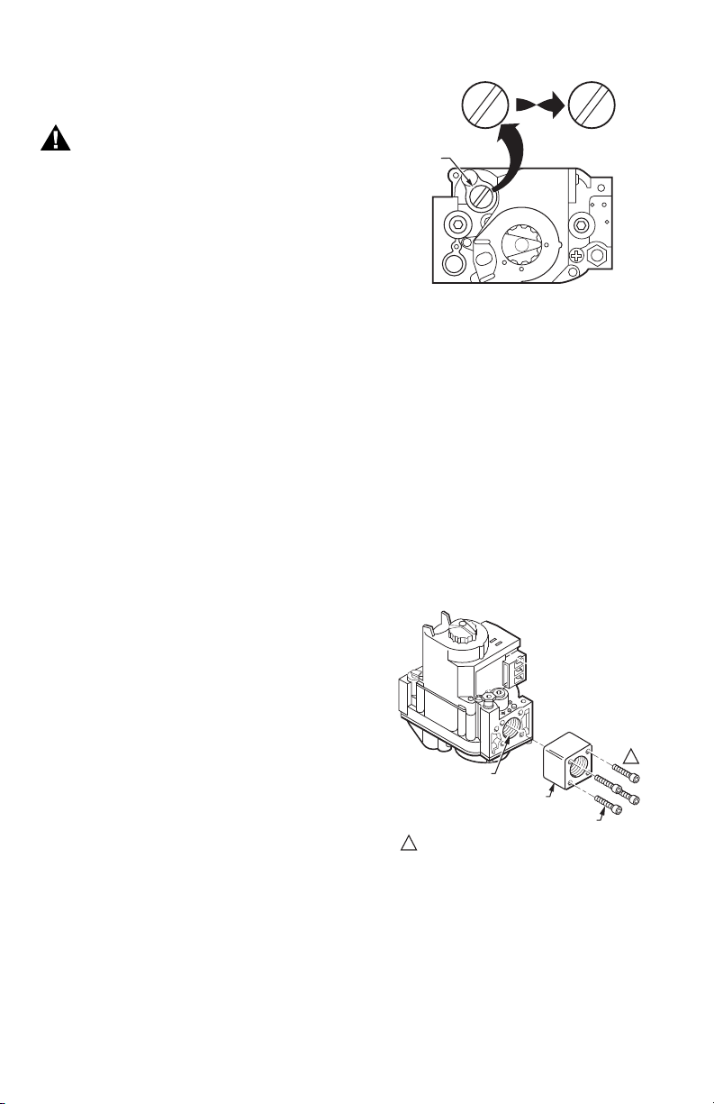
1. Remove the pressure regulator cap, Fig. 1.
2. Invert the cap so that the letters appear that
represent the gas type appropriate for the
appliance; NAT for natural (manufactured) gas, LP
for liquid petroleum gas.
3. Replace the cap and tighten firmly.
PRESSURE
REGULATOR
CAP
T
N
A
A
N
T
T
N
A
A
N
T
P
OR
L
OTHER SIDE
OF CAP
M11678
L
P
Fig. 1. Top view of convertible pressure regulator cap.
Install Adapters to Control
If adapters are being installed on the control, mount them
as follows:
Flanges
1. Choose the appropriate flange for your application.
Remove the seal over the ignition system control inlet or
outlet.
2. Make sure the O-ring is fitted in the groove of the
flange. If the O-ring is not attached or is missing, do
not use the flange.
3. With the O-ring facing the gas control, align the
screw holes on the control with the holes in the
flange.
4. Insert and tighten the screws provided with the
flange. See Fig. 2. Tighten the screws to 25 inchpounds of torque to provide a gas-tight seal.
VALVE OUTLET
FLANGE
9/64 INCH HEX SCREWS (4)
DO NOT OVERTIGHTEN SCREWS. TIGHTEN TO
1
25 INCH-POUNDS.
Fig. 2. Firmly fasten flange to valve,
but do not overtighten screws.
1
M9046
69-1226—04 4
Bushings
1. Remove the seal over the control inlet or outlet.
2. Apply a moderate amount of good quality pipe
compound to the bushing, leaving two end threads
bare. On an LP installation, use compound that is
resistant to LP gas. Do not use Teflon® tape.
3. Insert the bushing in the control and carefully thread
the pipe into the bushing until tight.
 Loading...