

V-Plex® Series Motion Sensors
1
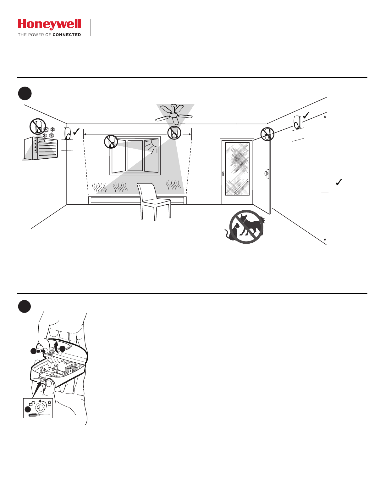
SELECT THE MOUNTING LOCATION
6' 9" - 8' 9"
(
2.1 - 2.7
m)
12”
(30 cm)
7' 6"
(2.3 m)
*
*
2
3
1
2
DT8050A-SN_step2-ii
OPEN THE SENSOR
DT8050A-SN
V-Plex® DUAL TEC® Motion Sensor with Anti-Mask - Installation Instructions
Mounting location guidelines:
• The optimal range is obtained at a mounting height
of 7’ 6” (2.3m).
• Allow a clear line-of-sight to all areas to protect.
• Avoid mounting anything within 12” (30cm) in front of the sensor*.
• Do not directly face windows.
• Avoid close proximity to moving machinery, fluorescent lights, and heating/cooling sources.
• Not for use in applications with pets.
1. Turn the arrow to point to the Unlock symbol.
2. Press firmly on housing latch.
3. Gently separate the front and rear housing.
#6
(3.5 mm)
A
A
B
B
B
A
B
#6 x 1 1/4"
(3.5 mm x 32 mm)
X X
A
B
BB
DT8050A-SN_step3-ii
3
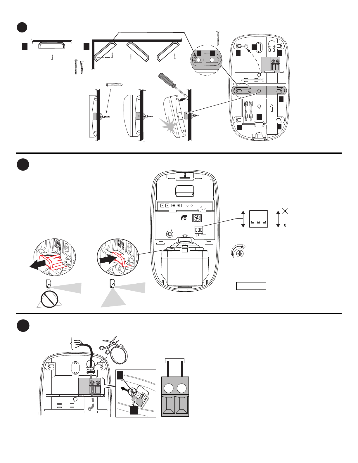
MOUNT THE SENSOR
*Look
Down
Enabled
Look
Down
Disabled
PU LL
TO DI SAB LE
LO OK DOW N
MAX
MW
SE NSI TIV ITY
ON
HIGH TRAFF IC INHI BIT
ANTI-M ASK
LED
OFF
ON
1 2 3
1 2 3
4
SENSOR COMPONENTS AND SETTINGS
ON
OFF
*Factory default
Microwave
Range
Adjustment
LED
*Anti-mask
Disabled
Anti-mask
Enabled
MW
SENSITIVITY
MAX
MIN
*
22-20 AWG
(0.31-0.52mm
2
)
1
2
DT8050A-SN_step5-ii
2 1
V-V
+
5
WIRE THE SENSOR
Polling Loop
9 - 13V
Pk - PK
[A
]
•
= Wall mounting holes.
• [B] = Corner mounting
holes.
• The rear tamper plate
MUST be mounted to a
stud, solid wood, or with
a robust wall anchor.
- 2 -

30 sec
30
0
45
20
10
MW
SENSITIVITY
MAX
MIN
Walk Test Reset
1/2 sec.
hold 4x
< 4’ (1.2m)
DT8050A-SN_step6-ii
ON
1 2 3
ON
OF F
6
WALK TEST THE SENSOR AND ADJUST AS NEEDED
7
DETECTION PATTERNS
Top View Side View
0
PLAN VIEW
ALL ZONES
7’
2 m
0
0
13’
4 m
20’
6 m
27’
8 m
33’
10 m
40’
12 m
7’
2 m
13’
4 m
20’
6 m
27’
8 m
33’
10 m
40’
12 m
7’
2 m
13’
4 m
20’
6 m
27’
8 m
33’
10 m
40’
12 m
46’
14 m
53’
16 m
7’
2 m
0
13’
4 m
20’
6 m
27’
8 m
33’
10 m
40’
12 m
46’
14 m
53’
16 m
A B C D
7’6”
2.3 m
1/2 sec.
hold 4x
< 4’ (1.2m)
Power
LED
Red
1. Apply power to the sensor. Initialization is complete when the LED
stops flashing slowly (about 30 seconds).
2. Turn the microwave sensitivity counterclockwise to reduce the microwave range (minimum = 16.4’ / 5m) and
close the sensor.
Yellow OFF
Green OFF ON PIR ON PIR OFF OFF
Walk Test Normal Trouble Anti-Mask
Up
Slow
Blink
ON
Alarm
ON
Microwave
ON
Alarm
ON
Microwave
Fast
Blink
OFF
OFF
Fast
Blink
3. Walk through the detection area and observe the LED.
4. Adjust the microwave range as necessary to meet installation requirements.
Walk test mode is active for 10 minutes, then automatically exits test mode, disables the LED and enters
normal operation mode. For an additional 10 minute walk test, enable walk test mode again with the flashlight
feature:
Note: During power up and walk test modes the LED is active regardless of the LED Enable/Disable DIP switch setting.
Flashlight Feature:
1. Use a flashlight with a bright light beam, and stand within 4’ (1.2 m) of the sensor.
2. Swing the light beam past the sensor IR window 3-5 times, holding the beam
on the window for 0.5 second each pass.
The flashlight feature is only available for the first 24 hours after power up.
- 3 -
Zones
A
B
C
D
2
Look-down
12
Lower
10
Intermediate
36
Long

TROUBLE*
NORMAL
Mask
1
Self-Test Failure
2
Red LED
Yellow LED
PROGRAM THE SENSOR
This sensor is a serial number device. Refer to the control
panel’s manual for instructions on registering devices and
programming.
For all V-Plex® panels, program the sensor Zone Type as INT
FOLLOWER 04 and the INPUT TYPE as “06” (for SL - Serial
Polling Device).
If using a Smart V-Plex® panel, program the sensor to
Standard mode [press “0” (No)] or SMART CONTACT mode
[press “1” (Yes)].
Standard Mode: The sensor includes a selectable High Traffic
Inhibit (HTI) feature. This feature reduces bus traffic with a
randomized delay (from 5 – 15 seconds) between alarm
signals after an alarm and restoral signal is sent. In
applications where this delay is not necessary, set DIP Switch
1 to OFF.
IMPORTANT: If using the Anti-Mask feature, the sensor MUST
be programmed to
Standard Mode.
Smart Contact Mode: In the Smart Contact mode, the sensor
automatically reduces bus traffic by not sending alarm signals
when disarmed.
ALL modes: Tamper, self-test failures and anti-mask1 signals
are sent without delays.
1
Anti-mask signals are only sent when Anti-mask is enabled
(DIP switch 2 ON), except during Microwave Walk Test mode.
See step 6.
LED OPERATION
The LED can be enabled in several ways:
− After power up mode the LED is enabled for 10 minutes (DIP
switch 3 ON or OFF).
− Remove and replace the front cover to enable the LED for
10 minutes (DIP switch 3 ON or OFF).
− Set DIP switch 3 ON (LED Enable); LED remains enabled
until disabled (switch 3 OFF). [Exception: When
programmed to Smart Contact mode and the system is
armed, the LED is always disabled.]
− Remote LED Enable. [If using a Smart V-Plex® panel, a
Remote LED Enable feature may be available, which allows
remote enabling of the LED if DIP switch 3 is OFF. (Refer to
the Burglary Walk-Test section in the control panel’s
manual.) Using this method, the LED remains enabled while
the panel is in the burglary walk test mode.]
MASK CONDITION
Normal Anti-Mask Condition
The sensor uses Active Infrared (AIR) technology to detect
masking. The sensor signals a mask condition when a variety
of materials and reflective objects are placed within 2 inches
(50mm) in front of the sensor. To avoid false mask alarms,
follow the mounting guidelines shown in Step 1.
Clearing an Anti-Mask Condition
When most masking materials or objects are removed, the
anti-mask condition will be cleared after several seconds.
When the cause of the anti-mask condition is any type of spray
or paint coating applied to the window, the window must be
replaced before the anti-mask condition can be cleared. After
replacing the window, perform a walk test on the sensor.
TROUBLESHOOTING
Off Off Flashing
Off Flashing Off
*TROUBLE CONDITIONS:
1
Mask condition: Sensor IR window is blocked or masked.
2
Self-Test Failure conditions:
• Microwave supervision failure: The sensor is operating in PIR mode only.
• PIR self-test failure: The sensor is disabled.
• Temperature compensation failure: The temperature compensation is disabled.
Depending on the Trouble condition, take the following corrective actions:
• Verify the sensor is not blocked or masked.
• Cycle power to the sensor.
• Walk test the sensor.
If the Trouble condition does not clear, replace the sensor.
SPECIFICATIONS
Range: 53’ x 72’ / 16 m x 22 m
Wall Mounting Height: 6’9” - 8’9” (2.1 m - 2.7 m); Optimal 7’6” (2.3 m)
Power: 9.0-13V PK – PK at polling loop terminals; (UL: 9.5-15VDC);
4 mA maximum.
Tampers: Cover & Wall
Microwave Frequencies: 10.525 GHz
RFI Immunity: 20V/m 10-1000MHz, 15V/m 1000-2700MHz
PIR White Light Immunity: 6,500 Lux typical
Fluorescent light filter: 50 Hz / 60 Hz.
Operating Temperature: 14° to 131° F / -10° to 55° C
Relative Humidity: 5 to 93% (UL tested at 93%); non-condensing
Temperature Compensation: Advanced Dual Slope
Dimensions: 4.57” H x 2.76” W x 1.69” D /
11.6 cm H x 7.0 cm W x 4.3 cm D
Weight: 5 oz / 142 g (net weight)
ACCESSORIES
SMB-10*
(P/N 0-000-110-01)
SMB-10C*
(P/N 0-000-111-01)
SMB-10T*
(P/N 0-000-155-01)
Cable* (P/N 1103)
Cable* (P/N 1104)
Cable* (P/N 1106)
Cable* (P/N 1107)
* Not evaluated by UL.
Swivel Mount Bracket
Swivel Mount Ceiling Bracket
Swivel Mount Bracket w/Tamper
General purpose, Solid 22 AWG,
4 conductor
General purpose, Stranded 22
AWG, 4 conductor
General purpose, Solid 22 AWG,
6 conductor
General purpose, Stranded 22
AWG, 6 conductor
- 4 -

FEDERAL COMMUNICATION
S COMMISSION STATEMENTS
FCC Notes:This transmitter must not be co-located or operating
in conjunction with any other antenna or transmitter.
APPROVAL LISTINGS
• FCC part 15, Class B verified
• IC ICES-003, Class B verified
• UL 639
• ULC S306-03
• SIA-PIR-01 Passive Infrared detector standard features for
false alarm immunity.
Product must be tested at least once each year.
All wiring must be in accordance with: the National Electrical
Code (ANSI/NFPA70); the Canadian Electrical Code, Part I
(where applicable); UL681, Standard for Installation and
Classification of Burglar and Holdup Alarm Systems; ULCS302, Standard for Installation and Classification of Burglar
Alarm Systems for Financial and Commercial Premises, Safes
and Vaults; ULC-S310, Standard for Installation and
Classification of Residential Burglar Alarm Systems; local
codes and the authorities having jurisdiction.
The products are intended to be powered by a power-limited
output of a UL/CUL Listed Burglar Alarm control unit, or via a
Listed UL603/ULC-S318 power-limited power supply that
provides 4 hours of standby power.
The sensor must be mounted indoors, within the protected
premises, and on a wooden stud, solid wood or with a robust
wall anchor.
UL Notes: All interconnecting devices must be UL Listed. The
anti-mask feature has not been evaluated by UL.
The user shall not make any changes or modifications to the equipment unless authorized by the Installation Instructions or User's Manual.
Unauthorized changes or modifications could void the user's authority to operate the equipment.
CLASS B DIGITAL DEVICE STATEMENT
This equipment has been tested to FCC requirements and has been found acceptable for use. The FCC requires the following statement for your
information:
This equipment generates and uses radio frequency energy and if not installed and used properly, that is, in strict accordance with the
manufacturer's instructions, may cause interference to radio and television reception. It has been type tested and found to comply with the limits for
a Class B computing device in accordance with the specifications in Part 15 of FCC Rules, which are designed to provide reasonable protection
against such interference in a residential installation. However, there is no guarantee that interference will not occur in a particular installation. If this
equipment does cause interference to radio or television reception, which can be determined by turning the equipment off and on, the user is
encouraged to try to correct the interference by one or more of the following measures:
• Reorient the receiving antenna until interference is reduced or eliminated.
• Move the radio or television receiver away from the receiver/control.
• Move the antenna leads away from any wire runs to the receiver/control.
• Plug the receiver/control into a different outlet so that it and the radio or television receiver are on different branch circuits.
• Consult the dealer or an experienced radio/TV technician for help.
INDUSTRY CANADA CLASS B STATEMENT
This Class B digital apparatus complies with Canadian ICES-003.
Cet appareil numérique de la classe B est conforme à la norme NMB-003 du Canada.
FCC / IC STATEMENT
This device complies with Part 15 of the FCC Rules, and Industry Canada’s license-exempt RSSs. Operation is subject to the following two
conditions: (1) This device may not cause harmful interference, and (2) This device must accept any interference received, including interference
that may cause undesired operation.
Cet appareil est conforme à la partie 15 des règles de la FCC et exempt de licence RSS d’Industrie Canada. Son fonctionnement est soumis aux
conditions suivantes: (1) Cet appareil ne doit pas causer d’interférences nuisibles. (2) Cet appareil doit accepter toute interférence reçue y compris
les interférences causant une réception indésirable.
- 5 -

REFER TO THE INSTALLATION INSTRUCTIONS FOR THE CONTROL WITH WHICH THIS DEVICE IS USED FOR DETAILS REGARDING LIMITATIONS OF
THE ENTIRE ALARM SYSTEM.
For patent information, see www.honeywell.com/patents
For the latest documentation and online support information, please go to:
http://www.security.honeywell.com/hsc/resources/MyWebTech/
For the latest U.S. warranty information, please go to: www.honeywell.com/security/hsc/resources/wa or
Please contact your local authorized Honeywell representative for product warranty information.
2017 Honeywell International Inc. Honeywell, V-Plex and DUAL TEC are registered trademarks of Honeywell International Inc.
All other trademarks are the properties of their respective owners. All rights reserved.
2 Corporate Center Drive, Suite 100
P.O. Box 9040, Melville, NY 11747
www.honeywell.com/security
P/N 800-23448-1 07/17 Rev A
 Loading...