

Page 1
VP525A,C
Pneumatic Radiator Valve
INSTALLATION INSTRUCTIONS
BEFORE INSTALLATION
This normally-open, single-seated, straight-through,
pneumatic valve provides two-position or proportional control
of two-pipe hot water or steam systems.
The valve can be installed in any position. The direction of
flow must be in the same direction as the arrow cast on the
valve body.
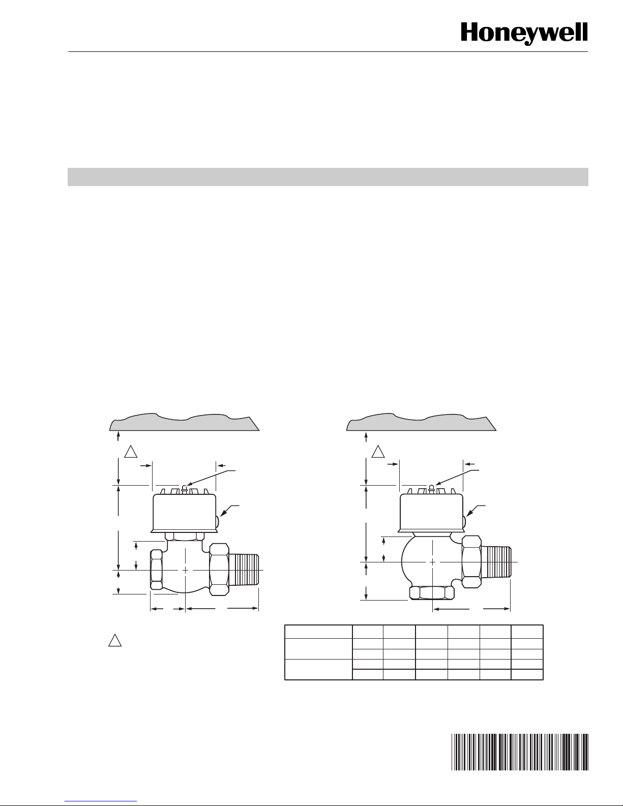
Refer to Fig. 1 for dimensions to determine the space required
for proper installation. Be sure to allow enough clearance
around the actuator top for servicing after installation.
1-1/2
(38)
1
2-1/4 DIAMETER (57)
AIR CONNECTION
FOR1/4 IN. (6 mm)
O.D. PLASTIC TUBING
SPECIFICATIONS
Body Pressure Rating: 150 psi (1034 kPa) maximum.
Controlled Medium Temperature (maximum):
VP525A: 180°F (82°C) maximum.
VP525C: 240°F (116°C) maximum.
Maximum allowable difference (alternating hot and cold
water): 140°F (78K).
Maximum Safe Air Pressure: 30 psi (207 kPa).
Maximum Differential Pressure for Quiet Service:
Water: 20 psi (138 kPa).
Steam (VP525C): 10 psi (69 kPa).
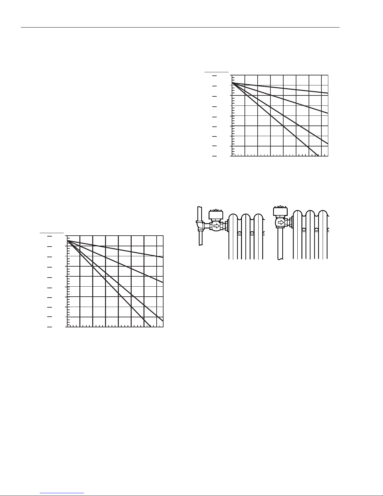
Close Off Ratings:
VP525A: See Fig. 2.
VP525C: See Fig. 3.
1-1/2
(38)
1
2-1/4 DIAMETER (57)
AIR CONNECTION
FOR1/4 IN. (6 mm)
O.D. PLASTIC TUBING
A
B
E
D
1
1-1/2 in. (38 mm) MINIMUM CLEARANCE TO REMOVE
ACTUATOR. 2 1/2 in. (63 mm) MINIMUM CLEARANCE
TO FACILITATE STRAIGHT ON TUBING CONNECTION.
IF CLEARANCE IS LESS THAN 2 1/2 in. (63 mm)
USE AN ELBOW.
M16449A
Fig. 1. VP525 threaded union body dimensions in in. (mm).
® U.S. Registered Trademark
Copyright © 2002 Honeywell International Inc.
All Rights Reserved
COVER FASTENER COVER FASTENER
A
B
D
C
BODY STYLE SIZE NPT
STRAIGHT THRU œ
MALE UNION OUTLET
ANGLE œ MALE
UNION OUTLET
1/2
3/4
1/2
3/4
A
3-1/2 (90)
3-1/2 (90)
3-1/4 (83)
3-1/8 (80)
B C D E
1-3/8 (35)
1-3/8 (35)
1 (25)
1 (25)
2-1/2
3
2-5/8
3
(63)
(76)
(66)
(76)
C
1-3/8 (35)
1-5/8 (41)
1-1/8 (29)
1-1/4 (32)
3/4
1-1/8
(19)
(29)
95-5544EF-1
Page 2
VP525A,C PNEUMATIC RADIATOR VALVE
A
8
A
INSTALLATION
Actuator Spring Selection
Series 2 VP525C Valves are built with a orange (3-10 psi)
actuator spring. Shipped with the valve is a loose green
(2-5 psi) spring. If desired, you can replace the orange spring
with the green. To make this change, you must remove the
cover fastener (see Fig. 1).
Threaded Union Body Version
Typical applications of straight-through and angle pattern
union connected valves are shown in Fig. 4. The direction of
flow must be toward the union connected end (the same
direction as the arrow cast on the valve body).
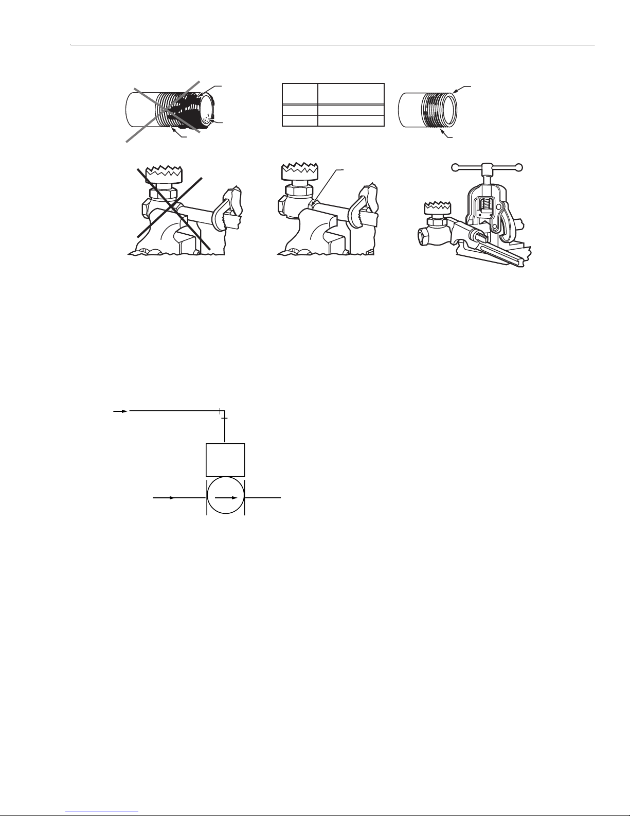
Use proper piping methods when installing the threaded union
body to prevent distortion of the valve body (see Fig. 5).
The union tail piece, with the union nut in place, is attached to
the radiator with a suitable spud wrench. The valve body is
threaded into the supply piping then secured to the tail piece
by means of the union nut.
ACTUATOR
SPRING RANGE
PSI (kPa)
2-5
3-10
7 12
(48) (83)
9
14
(62)
(97)
11
16
(76)
(110)
13
18
(90)
(124)
15
20
(103)
(138)
22
17
(152)
(117)
24
19
(165)
(131)
26
21
CONTROL AIR PRESSURE PSI (kPa)
(179)
(145)
23
28
(159)
(193)
25
30
0
(172)
(207)
20
(0)
(138)
VP525A CLOSE-OFF
AT MAXIMUM SYSTEM PRESSURE
C
= 0.63
v
C
= 2.0
v
C
v
= 3.0
C
v
= 5.0
40
60
80
100
(276)
(414)
(552)
CLOSE OFF DIFFERENTIAL
PRESSURE RATINGS PSI (kPa)
(689)
120
(827)
140
(965)
C7713
ACTUATOR
SPRING RANGE
PSI (kPa)
2-5
3-10
9
14
(62)
(97)
11
16
(76)
(110)
13
18
(90)
(124)
15
20
(103)
(138)
22
17
(152)
(117)
24
19
(165)
(131)
26
21
CONTROL AIR PRESSURE PSI (kPa)
(179)
(145)
23
28
(159)
(193)
25
30
(172)
0 20 40 60 80 100 120 140
(207)
(0) (138) (276) (414) (552) (689) (827) (965)
VP525C CLOSE-OFF
AT MAXIMUM SYSTEM PRESSURE
C
C
C
v
C
v
= 5.0
CLOSE OFF DIFFERENTIAL
PRESSURE RATINGS PSI (kPa)
Fig. 3. VP525C close-off ratings.
STRAIGHT THROUGH ANGLE
Fig. 4. Threaded union body connections.
= 0.63
v
v
= 2.0
= 3.0
C7714
M1644
Fig. 2. VP525A close-off ratings.
95-5544EF–1 2
Page 3
VP525A,C PNEUMATIC RADIATOR VALVE
2
EXCESS DOPE
MAY BLOCK DISC
OFF VALVE SEAT
LOOSE CHIPS
WRONG – TOO
MANY THREADS
PIPE SIZE
1/2 in. 1/2 in. (13 mm)
3/4 in. 9/16 in. (14 mm)
WRONG
VISE MAY SQUEEZE VALVE SEAT OUT OF
ROUND. IF VISE IS USED, GRIP ONLY THE
HEX NEXT TO PIPE BEING INSERTED.
VISE GRIPS HEX END NEXT TO PIPE
Fig. 5. Proper threaded valve installation practice.
TYPICAL OPERATION
An increase in control air pressure moves the valve stem
toward the closed position, modulating the flow through the
valve.
EFFECTIVE LENGTH
OF THREADS
RIGHT
RIGHT – FULL
THREAD (SEE TABLE)
VISE HOLDS PIPE
SECURELY
AGAINST TURNING
PARALLEL-JAW
WRENCH GRIPS HEX
OR FLATS NEXT TO PIPE
2 THREADS CLEAN –
MODERATE
AMOUNT OF DOPE
M16447
CONTROL
AIR
PRESSURE
VP525
SYSTEM
SUPPLY
Fig. 6. Typical operation.
C771
3 95-5544EF–1
Page 4

Automation and Control Solutions
Honeywell International Inc. Honeywell Limited-Honeywell Limitée
1985 Douglas Drive North 35 Dynamic Drive
Golden Valley, MN 55422 Scarborough, Ontario
95-5544EF–1 B.B. Rev. 12-02
M1V 4Z9
Printed in U.S.A. on recycled
paper containing at least 10%
post-consumer paper fibers.
www.honeywell.com
Page 5

Vanne pneumatique pour radiateur
VP525A et C
NOTICE D'INSTALLATION
AVANT D'INSTALLER CE PRODUIT…
Les VP525 A et C sont des vannes pneumatiques
normalement ouvertes à passage direct et à simple siège qui
assurent la commande tout ou rien ou la régulation
proportionnelle des systèmes à vapeur ou à eau chaude à
deux canalisations.
Cet appareil peut être installé dans n'importe quelle position.
Le fluide doit s'écouler dans le sens indiqué par la flèche sur
le corps de la vanne.
À l'aide des dimensions à la Fig. 1, déterminer l'espace
nécessaire pour l'installation de la vanne. S'assurer de laisser
un espace suffisant au-dessus de l'actionneur pour l'entretien
de la vanne lorsqu'elle sera installée.
1
38
(1-1/2)
57 DIAM (2-1/4)
A
RACCORD D'AIR POUR
CANALISATION EN
PLASTIQUE DE
6 mm (1/4 PO) DIAM EXT
ATTACHE DU
COUVERCLE
CARACTÉRISTIQUES TECHNIQUES
Pression nominale maximale du corps :
1034 kPa (150 psi).
Température maximale du fluide à régler :
VP525A : 82 °C (180 °F).
VP525C : 116 °C (240 °F).
Différence maximale admissible (alternance eau chaude-eau
froide) : 78 K (140 °F).
Pression de sécurité maximale - air : 207 kPa (30 psi).
Pression différentielle maximale pour fonctionnement
silencieux :
Eau : 138 kPa (20 psi).
Vapeur (VP525C) : 69 kPa (10 psi).
Pression différentielle maximale nominale à la fermeture :
VP525A : Voir la Fig. 2.
VP525C : Voir la Fig. 3.
1
38
(1-1/2)
57 DIAM (2-1/4)
A
RACCORD D'AIR POUR
CANALISATION EN
PLASTIQUE DE
6 mm (1/4 PO) DIAM EXT
ATTACHE DU
COUVERCLE
B
E
D
1
DÉGAGEMENT MINIMAL DE 38 mm (1-1/2 in.) POUR LE
DÉMONTAGE DE L'ACTIONNEUR. DÉGAGEMENT
MINIMAL DE 63 mm (2-1/2 in.) POUR FACILITER LE
RACCORDEMENT DES CANALISATIONS DROITES.
SI LE DÉGAGEMENT EST INFÉRIEUR À 63 mm
(2-1/2 in.), UTILISER UN COUDE.
MF16449A
Fig. 1. Encombrement du corps de vanne avec raccord union fileté VP525 en mm (po).
® Marque de commerce déposée aux É.-U.
Copyright © 2002 Honeywell Tous droits réservés
B
D
C
CORPS DE VANNE TAILLE (NPT)
DROIT œ SORTIE
RACCORD UNION M‚LE
EN ÉQUERRE œ SORTIE
RACCORD UNION M‚LE
1/2 (3-1/2)90 (1-3/8)
3/4 (3-1/2)90 (1-3/8)
1/2 (3-1/4)83 (1)
3/4 (3-1/8)80 (1)
A
B C D E
35
35
25
25
63
76
66
76
C
(2-1/2)
(3)
(2-5/8)
(3)
19
(1-3/8)35 (3/4)
29
(1-5/8)41 (1-1/8)
(1-1/8)29
(1-1/4)32
95-5544EF-1
Page 6

VANNE PNEUMATIQUE POUR RADIATEUR VP525A ET C
A
A
INSTALLATION
Choix du ressort de l'actionneur
Les vannes VP525C de la série 2 sont munies d'un ressort de
rappel orange (3-10 psi). Un ressort vert (2-5 psi) est
également fourni dans l'emballage. Pour remplacer le ressort
orange par le ressort vert, enlever l'attache du couvercle (voir
la Fig. 1).
Corps de vanne avec raccord union fileté
Les applications typiques des vannes à corps droit ou en
équerre avec raccord union sont illustrées à la Fig. 4.
Le fluide doit s'écouler vers l'extrémité du raccord union,
c'est-à-dire dans le sens indiqué par la flèche sur le corps de
la vanne.
Installer le raccord fileté selon les méthodes de tuyautage
recommandées pour empêcher le gauchissement du corps de
la vanne. (Voir la Fig. 5).
L'embout du raccord et l'écrou vissé sont d'abord fixés au
radiateur au moyen d'une clé à ergots de la bonne dimension.
Le corps de la vanne est ensuite vissé dans la canalisation
d'alimentation puis fixé à l'embout au moyen de l'écrou union.
GAMME DU RESSORT DE
RAPPEL DE L'ACTIONNEUR
EN kPa (PSI)
2-5
3-10
83
48
(12)
(7)
62
97
(9)
(14)
76
110
(11)
(16)
90
124
(13)
(18)
103
138
(15)
(20)
152
117
(22)
(17)
165
131
(24)
(19)
179
145
(26)
(21)
159
193
(23)
PRESSION DE L'AIR DE COMMANDE EN kPa (PSI)
172
(25)
(28)
207
(30)
PRESSION DE FERMETURE DE LA VP525A
SOUS PRESSION MAXIMALE DU SYSTÊME
C
C
v
= 5.0
0
138
276
414
(0)
(20)
(40)
PRESSION DIFFÉRENTIELLE
MAXIMALE ADMISSIBLE EN kPa (PSI)
(60)
552
(80)
v
(100)
C
= 3.0
689
= 2.0
v
C
v
(120)
= 0.63
827
965
(140)
CF7713
GAMME DU RESSORT
D'ACTIONNEUR
EN kPa (PSI)
2-5
3-10
62
97
(9)
(14)
76
110
(11)
(16)
90
124
(13)
(18)
103
138
(15)
(20)
152
117
(22)
(17)
165
131
(24)
(19)
179
145
(26)
(21)
159
193
(23)
(28)
172
207
(25)
PRESSION DE L'AIR DE COMMANDE EN kPa (PSI)
(30)
PRESSION DE FERMETURE DE LA VP525C
SOUS PRESSION MAXIMALE DU SYSTÊME
C
= 0.63
v
C
v
= 2.0
C
v
= 3.0
C
v
= 5.0
0
138 279 414 552 689 827 965
(0) (20) (40) (60) (80) (100) (120) (140)
PRESSION DIFFÉRENTIELLE MAXIMALE
ADMISSIBLE EN kPa (PSI)
CF7714
Fig. 3. Pression différentielle maximale nominale
à la fermeture de la VP525C.
DROIT EN ÉQUERRE
MF16448A
Fig. 4. Raccordements de vannes avec raccord fileté.
Fig. 2. Pression différentielle maximale nominale
à la fermeture de la VP525A.
95-5544EF–1 2
Page 7

VANNE PNEUMATIQUE POUR RADIATEUR VP525A ET C
A
UNE TROP GRANDE
QUANTITÉ DE MASTIC
RISQUE D'OBSTRUER
LE SIÊGE DE VANNE
ÉCLATS
INCORRECT – FILETAGE TROP LONG
TAILLE
DU TUYAU
1/2 po 13 mm (1/2 po)
3/4 po 14 mm (9/16 po)
INCORRECT
L'ÉTAU POURRAIT ÉCRASER LE SIÊGE
DE VANNE. AVEC L'ÉTAU, SERRER SEULEMENT
L'ÉCROU HEXAGONAL AU BOUT DU TUYAU À INSÉRER.
L'ÉTAU SERRE L'ÉCROU HEXAGONAL
DU CÏTÉ DU TUYAU
Fig. 5. Méthode recommandée pour l'installation d'une vanne avec raccord fileté.
FONCTIONNEMENT TYPIQUE
Une hausse de la pression d'air de commande pousse la tige
de la vanne vers sa position de fermeture, modulant ainsi le
débit du fluide dans la vanne.
LONGUEUR DE
FILETAGE EFFICACE
CORRECT
2 FILETS PROPRES –
QUANTITÉ SUFFISANTE
DE MASTIC
CORRECT – BONNE LONGUEUR
DE FILETAGE (VOIR LE TABLEAU)
LE TUYAU EST BIEN FIXÉ
DANS L'ÉTAU ET NE
PEUT TOURNER
LA CLÉ À M‚CHOIRES
PARALLÊLES SERRE
LA PARTIE DE L'ÉCROU
HEXAGONAL DU CÏTÉ DU TUYAU
MF16447
PRESSION D'AIR
DE COMMANDE
VP525
ALIMENTATION
DU SYSTÊME
CF7712
Fig. 6. Fonctionnement typique.
3 95-5544EF–1
Page 8

r
By using this Honeywell literature, you agree that Honeywell will have no liability for any damages arising out of your
use or modification to, the literature. You will defend and indemnify Honeywell, its affiliates and subsidiaries, from and
against any liability, cost, or damages, including attorneys’ fees, arising out of, or resulting from, any modification to the
literature by you.
Solutions de régulation et d‘automatisation
Honeywell Honeywell Limited-Honeywell Limitée
1985 Douglas Drive North 35, Dynamic Drive
Golden Valley, MN 55422 Scarborough (Ontario)
M1V 4Z9
95-5544EF–1 B.B. Rév. 12-02
Imprimé aux États-Unis sur du papie
recyclé contenant au moins 10 %
de fibres post-consommation.
www.honeywell.com
 Loading...