

Honeywell UV100E Product Data
whole-house air quality system
APPLICATION
When installed in forced air heating and cooling systems, the
UV100E Ultraviolet Air Treatment System kills airborne and
surface micro-organism contaminants.
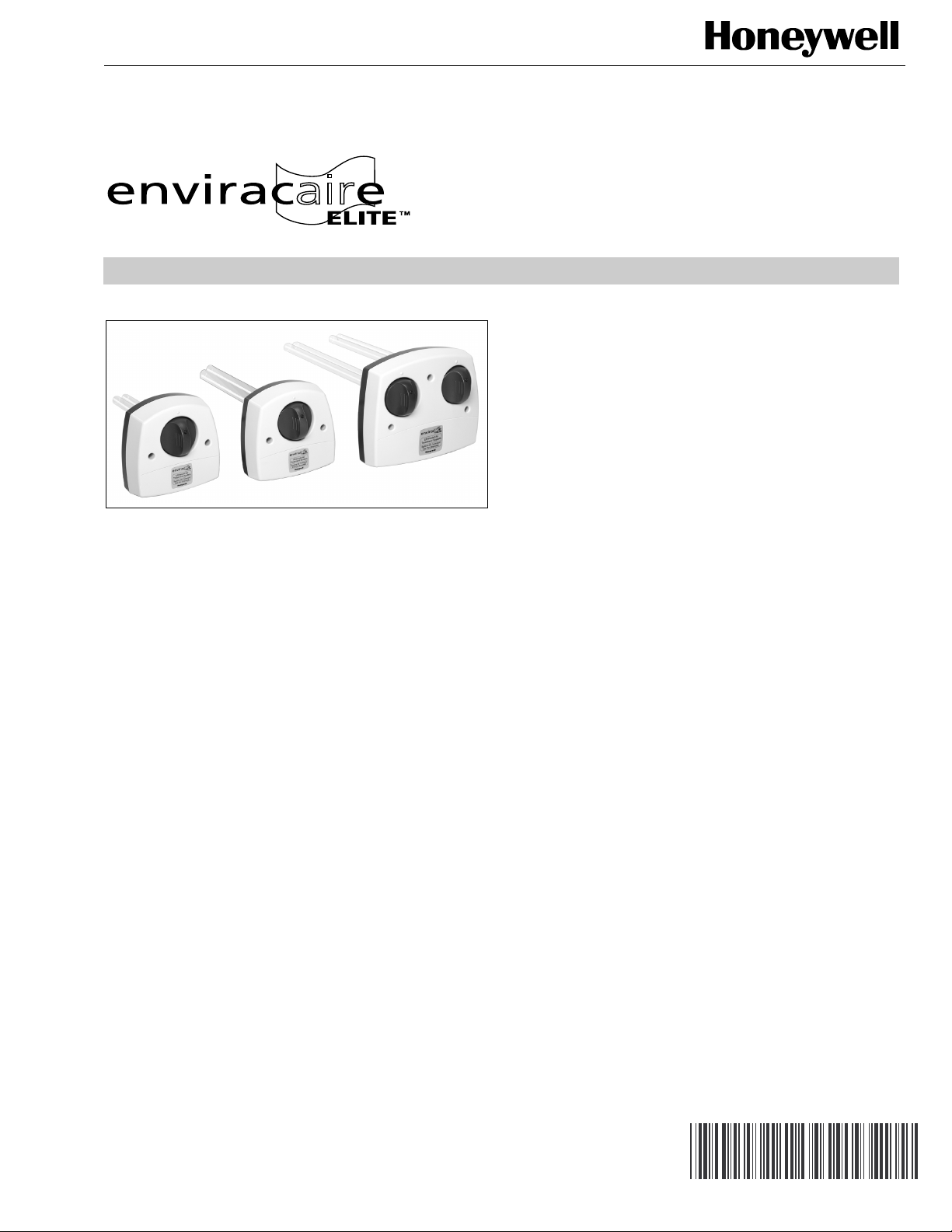
UV100E Ultraviolet
Air Treatment System
PRODUCT DATA
FEATURES
• UV-C light kills airborne and surface bacteria.
• Continuously emits ultraviolet energy.
• UV lamp does not produce ozone.
• Sealed unit design prevents accidental installer and
homeowner contact with the voltage and with the
ultraviolet rays.
• Safe design prevents lamps from lighting unless the
base is correctly mounted on the HVAC duct.
• Light pipe to safely view the lamp operation.
• Power cord that plugs into 120 Vac electrical outlet.
• Quick and easy lamp replacement.
• Easy lamp maintenance.
• AIRWATCH™ Indicator can be installed to remind
customers when to change lamp.
• To capture and minimize micro-organism pass-through
in residential heating, ventilation and air conditioning
(HVAC) systems, combine the Ultraviolet Air Treatment
System with a high-efficiency air filtration system that
includes an electronic air cleaner.
• Bold Enviracaire Elite look with blue and white styling.
• Five-year limited warranty.
® U.S. Registered Trademark
Copyright © 2002 Honeywell • All Rights Reserved
68-0249-1
UV100E ULTRAVIOLET AIR TREATMENT SYSTEM
SPECIFICATIONS
IMPORTANT
The specifications in this publication do not includenormal manufacturing tolerances; therefore, an individual unit may not exactly match the listed
specifications. This product is tested and calibrated
under closely controlled conditions and some minor
differences in performance can be expected if those
conditions are changed.
TRADELINE® Models available:
The UV100A Ultraviolet Air Treatment System is available in
three models: a single-lamp, moderate-efficiency return air
unit; a dual-lamp, high-efficiency return air unit; and an air
conditioner coil irradiation unit.
• UV100E single-lamp unit is mounted in the return air duct
of an HVAC system. It has moderate-efficiency
performance against airborne bacteria in return air
applications.
• UV100E dual-lamp unit is mounted in the return air duct of
an HVAC system. It has high-efficiency performance
against airborne bacteria in return air applications.
• UV100E coil irradiation unit is mounted downstream from
the air conditioner cooling coils or in the return air duct of
the HVAC system. The single-lamp unit reduces mold
growth and spores on duct surfaces, coils and drip pans.
• UV100A Dual-Lamp unit: Kills up to 87% of airborne
bacterial passing by the system.
— Test showed single-pass kill-rate of serratia marce-
scens bacteria in a clean metal 12 in. x 25 in. duct at
an airflow rate of 2000 cfm using new lamps.
• UV100A Single-Lamp unit: Kills up to 70% of airborne
bacteria passing by the system.
— Test showed single-pass kill-rate of serratia marce-
scens bacteria in a clean metal 12 in. x 25 in. duct at
an airflow rate of 2000 cfm using new lamps.
Approvals:
Underwriters Laboratories: File no. E212213.
The health aspects associated with the use of this product
and its ability to aid in disinfection of environmental air have
not been investigated by UL.
Electrical Ratings:
Power Rating: 120 Vac, 60 Hz.
Consumption:
Input Power
Model
Coil Irradiation 0.85 36
Single-Lamp Return 0.4 18
Dual-lamp Return 0.7 36 each lamp
(A)
Lamp Wattage
(W)
Efficiencies:
• UV100E Coil Irradiation unit: Kills up to 99.9% of mold on
system cooling coils.
— Test perfomed in a test duct showed reduction in col-
ony-forming aspergillus niger mold spores when surface was irradiated at a distance of 18 in. for three
hours in still air, using new lamps.
Temperature Ratings:
Ambient Temperature Range: 30°F to 104°F (-2°C to 40°C).
Lamp Temperature Range: 30°F to 104°F (-2°C to 40°C).
Relative Humidity:
Up to 95% rh, non-condensing.
Dimensions:
See Fig. 2.
ORDERING INFORMATION
When purchasing replacement and modernization products from your TRADELINE® wholesaler or distributor, refer to the
TRADELINE® Catalog or price sheets for complete ordering number.
If you have additional questions, need further information, or would like to comment on our products or services, please write or
phone:
1. Your local Home and Building Control Sales Office (check white pages of your phone directory).
2. Home and Building Control Customer Relations
Honeywell, 1885 Douglas Drive North
Minneapolis, Minnesota 55422-4386
In Canada—Honeywell Limited/Honeywell Limitée, 35 Dynamic Drive, Scarborough, Ontario M1V 4Z9.
International Sales and Service Offices in all principal cities of the world. Manufacturing in Australia, Canada, Finland, France,
Germany, Japan, Mexico, Netherlands, Spain, Taiwan, United Kingdom, U.S.A.
68-0249-1 2
INSTALLATION
UV100E ULTRAVIOLET AIR TREATMENT SYSTEM
When Installing this Product…
1. Read these instructions carefully. Failure to follow them
could damage the product or cause a hazardous
condition.
2. Check the rating given in the instructions and on the
product to make sure the product is suitable for your
application.
3. Installer must be a trained, experienced service
technician.
4. After installation is complete, check out product
operation as provided in these instructions.
CAUTION
Personal Injury Hazard.
Power supply can cause electrical shock.
Disconnect power supply before beginning installation.
Do not open base unit or lamp knob; there are no
user-serviceable components inside.
WARNING
UV Light Hazard.
Harmful to bare skin and eyes.
Can cause temporary or permanent loss of vision.
Never look at the lamps while illuminated.
Only view illumination by way of the light indicator on
the lamp knob.
To prevent exposure to ultraviolet light, disconnect
power to the ultraviolet air treatment system before
servicing any part of the heating/air conditioning
system.
Do not mount device in location that allows ultraviolet
light to be seen after installation.
Do not attempt to bypass the duct mount switch.
Selecting Mounting Location
CAUTION
Equipment Damage Hazard.
Ultraviolet light can cause color shift or structural
degradation of plastic HVAC materials.
Select mounting location that prevents exposure to
plastic components with unknown resistance to
ultraviolet light. Three-feet minimum is recommended
between ultraviolet lamps and plastic-fabricated
devices (such as humidifiers and non-fiberglass media
filters).
IMPORTANT
If mounting options are limited, protect plastic or rubber material listed in CAUTION with ultraviolet-resistant material such as aluminum foil duct tape.
NOTE: When the installer is uncertain about whether the
drip pan in the installation can tolerate UV exposure,
consult the UV exposure white paper, form no. 508788, at hbctechlit.com Web site.
1. The ultraviolet air treatment system can be mounted in
any orientation.
2. Choose a location that is readily accessible for regular
inspection and cleaning.
3. Allow clearance in front of the device for removing the
lamp assemblies. See Fig. 2 for lamp assembly lengths.
4. Select mounting location that prevents exposure to
plastic components with unknown resistance to
ultraviolet light. A minimum of three feet is required
between the ultraviolet lamps and devices fabricated of
plastic, such as humidifiers.
5. Mount the ultraviolet air treatment system to non-lined
metal ductwork. Do not mount in a location that permits
ultraviolet exposure to plastic flexible duct liner.
CAUTION
Sharp Edges Hazard.
Can cause personal injury.
Be careful when inserting ultraviolet device into the
sheet metal cutout.
Wear protective gloves when working near sheet
metal.
Duct Mounting
Use the following instructions to mount the air treatment
system on the air duct of an HVAC system:
1. Disconnect power to the HVAC system before installing
the Ultraviolet Air Treatment System.
2. Determine the location for installation (see Fig. 1):
a. The single-lamp and dual-lamp units require an
easily-accessible, flat mounting surface on the
metal return air duct of the HVAC system. The coil
irradiation unit requires an easily-accessible, flat
mounting surface on the metal supply air duct of the
HVAC system. The coil irradiation unit must be
located so the lamp surrounds the evaporator coil
and drip pan with ultraviolet light.
b. The duct mounting location must be a minimum of
8 in. wide. See Fig. 2.
c. The depth of the duct must accommodate the full
length of the ultraviolet lamp for your model as
shown in Fig. 2.
d. The unit should be located as far away as possible
from any rubber or plastic components, such as
isolators, in the duct.
e. The space adjacent to the mounting location must
be large enough to allow for ultraviolet lamp
installation and removal.
f. A 120 Vac electrical outlet must be within range of
the unit to plug in the power cord.
3 68-0249-1
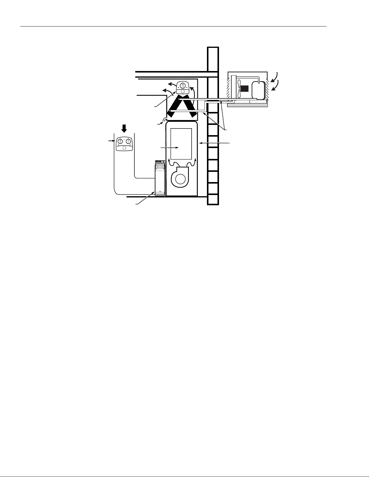
UV100E ULTRAVIOLET AIR TREATMENT SYSTEM
CONDITIONED AIR
COIL IRRADIATION
UNIT LOCATION
RETURN
CONDENSATE
AIR
SINGLE-LAMP
AND DUAL-LAMP
UNIT LOCATION
EXCHANGER
TO ROOM
DRAIN
HEAT
ELECTRONIC AIR CLEANER
CONDENSER
COOLING AIR
REMOTE CONDENSER
SECTION (HIGH SIDE)
REFRIGERANT
PIPING
FURNACE
HIGH EFFICIENCY
AIR CLEANER
M13529A
Fig. 1. Possible mounting locations for Ultraviolet Air Treatment Systems.
68-0249-1 4
 Loading...