

Page 1
Honeywell
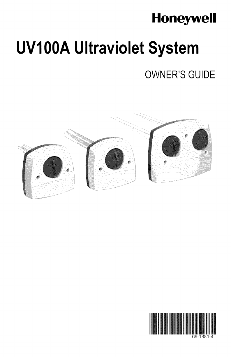
UVIOOAUltravioletSystem
OWNER'SGUIDE
69-1381-4
Page 2
UVIOOA ULTRAVIOLET SYSTEM
IMPORTANT
Please read these instructions and keep them in your records.
HOWYOURULTRAVIOLETAIR TREATMENTSYSTEM
ORSURFACETREATMENTSYSTEMWORKS
Depending on installation, your Ultraviolet System can operate as an Air Treatment
System or as a Surface Treatment System.
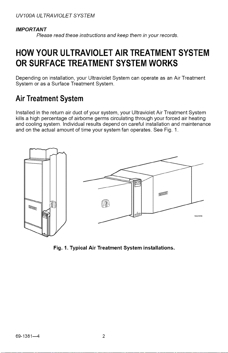
AirTreatmentSystem
Installed in the return air duct of your system, your Ultraviolet Air Treatment System
kills a high percentage of airborne germs circulating through your forced air heating
and cooling system. Individual results depend on careful installation and maintenance
and on the actual amount of time your system fan operates. See Fig. 1.
Fig. 1. Typical Air Treatment System installations.
69-13814 2
Page 3
UVIOOA ULTRAVIOLET SYSTEM
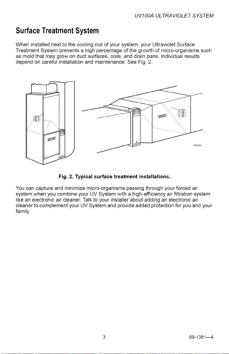
SurfaceTreatmentSystem
When installed next to the cooling coil of your system, your Ultraviolet Surface
Treatment System prevents a high percentage of the growth of micro-organisms such
as mold that may grow on duct surfaces, coils, and drain pans. Individual results
depend on careful installation and maintenance. See Fig. 2.
Fig. 2. Typical surface treatment installations.
You can capture and minimize micro-organisms passing through your forced air
system when you combine your UV System with a high-efficiency air filtration system
like an electronic air cleaner. Talk to your installer about adding an electronic air
cleaner to complement your UV System and provide added protection for you and your
family.
3 69-13814
Page 4
UVIOOA ULTRAVIOLET SYSTEM
BESURETOREADWARNINGSANDCAUTIONS
BEFOREUSINGYOURUVSYSTEM
_WARNING
UV Light Hazard.
Harmful to bare skin and eyes.
Can cause temporary or permanent loss of vision.
Never took at bulbs while illuminated.
View illumination only through light indicator located on lamp handle.
To prevent exposure to ultraviolet light, disconnect power to Ultraviolet System
before servicing any part of heating and air conditioning system.
Do not mount device in location that allows ultraviolet light to be seen after
installation.
Do not attempt to bypass duct mount switch.
Do not attempt to open housing; unit is sealed to prevent ultraviolet light
exposure.
CAUTION
Personal Injury Hazard.
Power supply can cause electrical shock.
Disconnect power supply before cleaning or replacing ultraviolet bulb(s).
Do not open base unit or lamp handle; there are no user-serviceable
components inside.
CAUTION
Breakable Glass Hazard.
Can cause personal injury.
Be careful when inserting bulb(s) into tamp base.
Wear protective gloves when handling bulb(s).
A
/_ CAUTION
UV Lamp Burn Hazard.
Harmful to bare skin.
Can cause severe burns.
Disconnect power 15 minutes before removing the ultraviolet bulb(s)
69-13814 4
Page 5

UVIOOA ULTRAVIOLET SYSTEM
MERCURYNOTICE
This device contains mercury in the sealed ultraviolet bulb(s). Do not place
your used bulb(s) in the trash. Dispose of properly.
Broken Bulb Cleanup.
Do not use a household vacuum.
Sweep debris (phosphor/glass) into a plastic bag and dispose of properly.
Contact your local waste management authority for instructions regarding
recycling and the proper disposal of old bulb(s).
5 69-13814
Page 6

UVIOOA ULTRAVIOLET SYSTEM
HOWYOUCANCHECKYOURULTRAVIOLETSYSTEM
Your UV System is designed to prevent accidental contact with electrical voltage and
with ultraviolet rays in the sealed unit_he ultraviolet lamp does not illuminate unless
the base is mounted on your forced air system duct.
It is recommended that every month you verify that your ultraviolet lamp is operating.
View the bulb only through the lamp light indicator on the lamp handle. See Fig. 3.
Do not attempt to look into the duct at the ifluminated bulb(s).
LAMP LIGHT INDICATOR
© ©
Fig. 3. Lamp light indicator.
69-13814 6
M22840
Page 7

UVIOOA ULTRAVIOLET SYSTEM
HOWYOUCANMAINTAINYOURUV SYSTEM
You should regularly clean your UV System to maintain peak effectiveness of your air
treatment or surface treatment system. Replace the ultraviolet bulb once a year.
QuarterlyBulb Cleaning
Bulb cleaning is recommended as routine maintenance four times a year or every
three months. Use the UV Bulb Cleaning Reminder Schedule, Fig. 4, to help establish
and track your regular cleaning schedule.
UV BULB CLEANING REMINDER SCHEDULE
INSTALLATION DATE: (month) (year)_
YEAR
J F M A M J J A S O N D
M13516A
Fig. 4. UV bulb cleaning reminder schedule.
To clean your bulb(s):
1. Disconnect the power to your heating and cooling system.
2. Unplug or turn off power to your UV System and allow the bulb(s) to cool for at
least 15 minutes.
7 69-13814
Page 8

UVIOOA ULTRAVIOLET SYSTEM
3.
Rotate your tamp handle counterclockwise and gently pull the lamp handle to
remove the bulb. See Fig. 5.
Fig. 5. Remove lamp bulb.
4.
Holding the tamp handle, wipe the lamp glass using a soft cloth dampened with
glass cleaner. If you touch the tamp glass with your hands, be sure to clean the
area of any oils left from bare hands. See Fig. 6.
M22842
Fig. 6. Clean glass with soft cloth.
5. Also wipe away any dust that may have collected between the lamp light
indicator on the base and the black bulb base. See Fig. 7.
LIGHT INDICATOR BASE
Fig. 7. Wipe lamp light indicator base.
69-13814 8
Page 9

UVIOOA ULTRAVIOLET SYSTEM
6.
Dry bulb with a clean, dry cloth.
7.
Insert the bulb into the base with the tamp light indicator at the eleven o'clock
position. Continue pushing and gently rotating counterclockwise until the lamp
handle inserts fully into the base. See Fig. 8.
Fig. 8. Position bulb for insertion back into the lamp base.
8.
Rotate the tamp handle clockwise until it snaps into place with the lamp light
indicator aligned with the raised button on the unit cover. See Fig. 9.
Fig. 9. Snap bulb into place.
9 69-13814
M22850
Page 10
UVIOOA ULTRAVIOLET SYSTEM
9. Reconnect power to your UV System.
10. Verify that your ultraviolet bulbs are operating by viewing only through the tamp
light indicator on the lamp handle. Never look directly at your bulb while it is
illuminated.
11. Reconnect power to your heating and cooling system.
Bulb Replacement
Annual replacement of the bulb in your ultraviolet lamp is required to maintain
effectiveness.
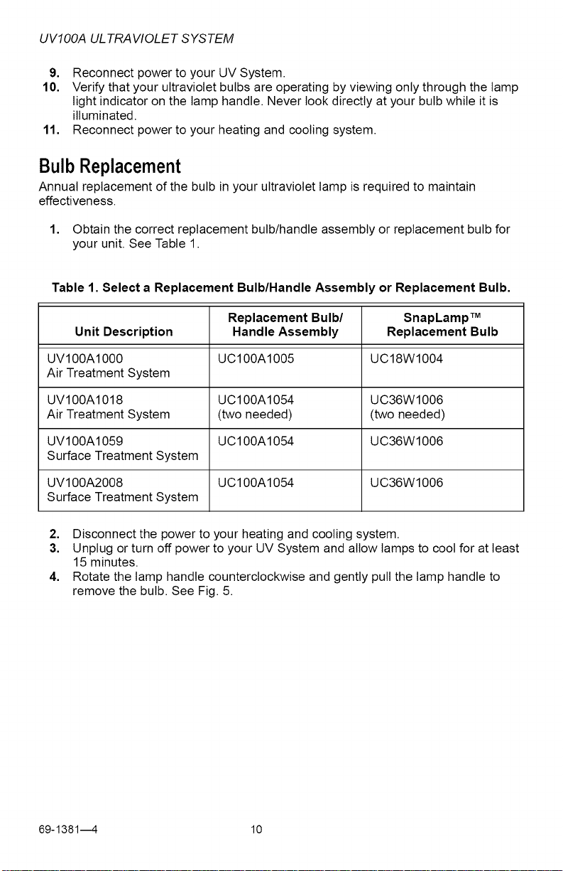
1. Obtain the correct replacement bulb/handle assembly or replacement bulb for
your unit. See Table 1.
Table 1. Select a Replacement Bulb/Handle Assembly or Replacement Bulb.
Replacement Bulb/ SnapLamp TM
Unit Description Handle Assembly Replacement Bulb
UV100A1000 UC100A1005 UC18W1004
Air Treatment System
UV100A1018 UC100A1054 UC36W1006
Air Treatment System (two needed) (two needed)
UV100A1059 UC100A1054 UC36W1006
Surface Treatment System
UV100A2008 UC100A1054 UC36W1006
Surface Treatment System
2. Disconnect the power to your heating and cooling system.
3. Unplug or turn off power to your UV System and allow lamps to cool for at least
15 minutes.
4. Rotate the lamp handle counterclockwise and gently pull the lamp handle to
remove the bulb. See Fig. 5.
69-13814 10
Page 11

UVIOOA ULTRAVIOLET SYSTEM
5.
If you have a SnapLamp TM handle, follow steps 5 and 6; otherwise, proceed to
step 7. Grasp the SnapLamp TM handle in one hand and the lamp glass in the
other and pull straight apart. See Fig. 10.
M22852
Fig. 10. Disconnect lamp glass from SnapLamp TM handle.
6.
Insert the new tamp glass into the SnapLamp TM handle by aligning the key and
pushing straight together. See Fig. 11.
M22854
)
J
Fig. 11. Replace lamp glass in SnapLamp TM handle.
7. Insert the bulb into the base with the tamp light indicator at the eleven o'clock
position. Continue pushing and gently rotating counterclockwise until the lamp
handle inserts fully into the base. See Fig 8.
8. Rotate the lamp clockwise until it snaps into place with the tamp light indicator
aligned with the raised button on the unit cover. See Fig. 9.
9. Reconnect power to your UV System.
10. Verify that your ultraviolet bulb is operating by viewing only through the lamp
light indicator on the lamp handle. Never look directly at your bulb while
illuminated.
11. Reconnect power to your heating and cooling system.
11 69-13814
Page 12

UVIOOA ULTRAVIOLET SYSTEM
LimitedWarranty
Honeywell warrants this product, excluding bulbs, to be free from defects in the workmanship or
materials, under normal use and service, for a period of one (1) year from the date of purchase by
the consumer. If, at any time during the warranty period, the product is defective or malfunctions,
Honeywell shall repair or replace it (at Honeywell's option) within a reasonable period of time.
If the product is defective,
(i)return it, with a bill of sale or other dated proof of purchase, to the retailer from which you
purchased it, or
(ii)package it carefully, along with proof of purchase (including date of purchase) and a short
description of the malfunction, and mail it, postage prepaid, to the following address:
Honeywell Return Goods
Dock 4 MN10-3860
1885 Douglas Dr. N
Golden Valley, MN 55422
This warranty does not cover removal or reinstallation costs. This warranty shall not apply if it is
shown by Honeywell that the defect or malfunction was caused by damage which occurred while
the product was in the possession of a consumer.
Honeywell's sole responsibility shall be to repair or replace the product within the terms stated
above. HONEYWELL SHALL NOT BE LIABLE FOR ANY LOSS OR DAMAGE OF ANY KIND,
INCLUDING ANY INCIDENTAL OR CONSEQUENTIAL DAMAGES RESULTING, DIRECTLY OR
INDIRECTLY, FROM ANY BREACH OF ANY WARRANTY, EXPRESS OR IMPLIED, OR ANY
OTHER FAILURE OF THIS PRODUCT. Some states do not allow the exclusion or limitation of
incidental or consequential damages, so this limitation may not apply to you.
THIS WARRANTY IS THE ONLY EXPRESS WARRANTY HONEYWELL MAKES ON THIS
PRODUCT. THE DURATION OF ANY IMPLIED WARRANTIES, INCLUDING THE WARRANTIES
OF MERCHANTABILITY AND FITNESS FORA PARTICULAR PURPOSE, IS HEREBY LIMITED
TO THE ONE YEAR DURATION OF THIS WARRANTY. Some states do not allow limitations on
how long an implied warranty lasts, so the above limitation may not apply to you.
This warranty gives you specific legal rights, and you may have other rights which vary from state
to state.
If you have any questions concerning this warranty, please write Honeywell Customer Relations,
1985 Douglas Dr. N MN10-1461, Golden Valley, MN 55422 or call 1-800-468-1502, Monday-
Friday, 7:00 a.m. to 5:30 p.m., Central time. In Canada, write Honeywell Limited/Honeywell
Limitee, 35 Dynamic Dr, ON15, Toronto, Ontario MlV4Z.
Automation and Control Solutions
Honeywell International Inc. Honeywell Limited-Honeywell Limitee
1985 Douglas Drive North 35 Dynamic Drive
Golden Valley, MN 55422 Toronto, Ontario M1V 4Z9
yourhome.honeywell.com
Printed in U.S.A. on recycled
paper containing at least 10%
post-consumer paper fibers.
® U.S. Registered Trademark
© 2007 Honeywell International tnc.
69-13814 M.S. Rev. 03-07
Honeywell
 Loading...