

Page 1

UDC 2300
UDC 3000
UDC 3300
UDC 5000
UDC 6000
UDC 6300
Universal Digital Controllers
RS422/485 ASCII Communications
Option
Product Manual
51-51-25-35G
5/99
Page 2

Copyright, Notices, and Trademarks
Printed in U.S.A. – © Copyright 1999 by Honeywell Inc.
Rev G, 5/99
While this information is presented in good faith and believed to be accurate,
Honeywell disclaims the implied warranties of merchantability and fitness for a
particular purpose and makes no express warranties except as may be stated in its
written agreement with and for its customer.
In no event is Honeywell liable to anyone for any indirect, special, or consequential
damages. The information and specifications in this document are subject to
change without notice.
This document was prepared using Information Mapping® methodologies and
formatting principles.
UDC 2300, UDC 3000, UDC 3300, UDC 5000, UDC 6000, and UDC 6300 are U.S.
trademarks of Honeywell Inc.
Information Mapping® is a registered trademark of Information Mapping, Inc.
Honeywell
Industrial Automation and Control
Automation College
100 Virginia Drive
Fort Washington, PA 19034
ii RS422/485 ASCII Communications Option Product Manual 5/99
Page 3

About This Publication
The UDC manual for RS422/485 ASCII communications option contains the following sections:
Section 1 – Overview
Section 2 – Installation
Section 3 – Establishing Communications
Section 4 – Read and Write Operations
Section 5 – Reading, Writing, and Overriding Parameters on UDC 3000
Versa-Pro Controllers
Section 6 – Reading, Writing and Overriding Parameters on UDC 5000
Ultra-Pro Controllers
Section 7 – Reading, Writing, and Overriding Parameters on UDC 6000
Process Controllers
Section 8 – Reading, Writing, and Overriding Parameters on UDC 6300
Process Controllers
Section 9 – Reading, Writing, and Overriding Parameters on UDC 3300
Process Controllers
Section 10 – Reading, Writing, and Overriding Parameters on UDC 2300
Process Controllers
Section 11 – Operating the Controller with Communications Option
Section 12 – ASCII Conversion Table
Section 13 – Cable Specifications
Communication between your computer and the UDC Controller is accomplished for one piece of
information (parameter) at a time. Each parameter has an associated identifying code.
The Identifying Code and Format Code will be listed along with information pertaining to that
parameter.
The identifying codes are grouped in the same order as they appear in the controller configuration
prompts.
5/99 RS422/485 ASCII Communications Option Product Manual iii
Page 4

Contents
SECTION 1 – OVERVIEW..................................................................................................1
1.1 Introduction...................................................................................................1
1.2 Message Exchange Protocols ......................................................................2
1.3 Field Upgrade...............................................................................................3
SECTION 2 – INSTALLATION...........................................................................................5
2.1 Introduction...................................................................................................5
2.2 RS232 to RS485 Converters........................................................................6
2.3 Using a Black Box Converter........................................................................7
2.4 Using a Westermo Converter .......................................................................9
2.5 Wiring Diagrams.........................................................................................11
SECTION 3 – ESTABLISHING COMMUNICATIONS AND TESTING ............................15
3.1 Preparing the Controller for Communications.............................................15
3.2 Programming..............................................................................................19
3.3 Message Exchange....................................................................................20
3.4 Request Messages.....................................................................................21
3.5 Response Messages..................................................................................24
3.6 Status Codes..............................................................................................26
3.7 Checksum Protocol (for Data Security) ......................................................28
3.8 Shed ...........................................................................................................34
3.9 Loopback (UDC 2300, UDC 3000, UDC 3300 Only)..................................35
3.10 Recovering from Communications Failures................................................37
SECTION 4 – READ AND WRITE OPERATIONS...........................................................41
4.1 Read Operations.........................................................................................41
4.2 Read Analog Parameters ...........................................................................42
4.3 Read Digital Parameters.............................................................................45
4.4 Write Operations.........................................................................................47
4.5 Write Analog Parameters............................................................................48
4.6 Write Digital Parameters.............................................................................52
SECTION 5 – READ, WRITE AND OVERRIDE PARAMETERS – UDC3000.................55
5.1 UDC 3000 Overview...................................................................................55
5.2 UDC 3000 Reading Control Data ...............................................................57
5.3 UDC 3000 Read Option Status...................................................................58
5.4 UDC 3000 Miscellaneous Read Only’s.......................................................59
5.5 UDC 3000 Setpoints...................................................................................61
5.6 UDC 3000 Using a Computer Setpoint.......................................................62
5.7 UDC 3000 Overriding Input 1 .....................................................................63
5.8 UDC 3000 Canceling the Override.............................................................64
5.9 UDC 3000 Reading or Changing the Output..............................................65
5.10 UDC 3000 Local Setpoint/PID Set Selection /Setpoint Ramp Status.........66
5.11 UDC 3000 Configuration Parameters.........................................................68
SECTION 6 – READ, WRITE AND OVERRIDE PARAMETERS – UDC5000.................85
6.1 Overview.....................................................................................................85
6.2 Reading Control Data.................................................................................88
6.3 Option Status..............................................................................................89
iv RS422/485 ASCII Communications Option Product Manual 5/99
Page 5

6.4 Miscellaneous Read Only’s........................................................................ 90
6.5 Setpoints.................................................................................................... 92
6.6 Using a Computer Setpoint........................................................................ 93
6.7 Overriding the Inputs.................................................................................. 95
6.8 PV, Setpoint, or Input Override Status or Cancellation.............................. 97
6.9 Reading or Changing the Output ............................................................... 98
6.10 Local Setpoint/PID Selection/Setpoint Ramp Status.................................. 99
6.11 Configuration Parameters ........................................................................ 101
SECTION 7 – READ, WRITE AND OVERRIDE PARAMETERS – UDC6000............... 127
7.1 Overview .................................................................................................. 127
7.2 Reading Control Data............................................................................... 130
7.3 Read Options Status................................................................................ 131
7.4 Miscellaneous Read Only’s...................................................................... 132
7.5 Setpoints.................................................................................................. 134
7.6 Using a Computer Setpoint...................................................................... 135
7.7 PV or Setpoint Override Selections.......................................................... 137
7.8 Reading or Changing the Output ............................................................. 138
7.9 Local Setpoint/PID Selection/Setpoint Ramp Status................................ 139
7.10 Configuration Parameters ........................................................................ 142
SECTION 8 – READ, WRITE AND OVERRIDE PARAMETERS – UDC6300............... 177
8.1 Overview .................................................................................................. 177
8.2 Reading Control Data............................................................................... 180
8.3 Read Options Status................................................................................ 181
8.4 Miscellaneous Read Only’s...................................................................... 182
8.5 Setpoints.................................................................................................. 186
8.6 Using a Computer Setpoint...................................................................... 187
8.7 PV or Setpoint Override Selections.......................................................... 189
8.8 Reading or Changing the Output ............................................................. 190
8.9 Local Setpoint/PID Selection/Setpoint Ramp Status................................ 191
8.10 Configuration Parameters ........................................................................ 194
SECTION 9 – READ, WRITE AND OVERRIDE PARAMETERS – UDC3300............... 231
9.1 UDC 3300 Overview ................................................................................ 231
9.2 UDC 3300 Reading Control Data............................................................. 234
9.3 UDC 3300 Read Options Status.............................................................. 235
9.4 UDC 3300 Miscellaneous Read Only’s.................................................... 236
9.5 UDC 3300 Setpoints ................................................................................ 238
9.6 UDC 3300 Using a Computer Setpoint.................................................... 239
9.7 UDC 3300 PV or Setpoint Override Selections........................................ 241
9.8 UDC 3300 Reading or Changing the Output............................................ 242
9.9 UDC 3300 Local Setpoint/PID Selection/Setpoint Ramp Status.............. 243
9.10 UDC 3300 Configuration Parameters ...................................................... 246
SECTION 10 – READ, WRITE AND OVERRIDE PARAMETERS – UDC2300............. 277
10.1 UDC 2300 Overview ................................................................................ 277
10.2 UDC 2300 Reading Control Data............................................................. 280
10.3 UDC 2300 Read Options Status.............................................................. 281
10.4 UDC 2300 Miscellaneous Read Only’s.................................................... 282
10.5 UDC 2300 Setpoints ................................................................................ 284
10.6 UDC 2300 Using a Computer Setpoint.................................................... 285
10.7 UDC 2300 PV or Setpoint Override Selections........................................ 287
10.8 UDC 2300 Reading or Changing the Output............................................ 288
10.9 UDC 2300 Local Setpoint/PID Selection/Setpoint Ramp Status.............. 289
10.10 UDC 2300 Configuration Parameters ...................................................... 292
5/99 RS422/485 ASCII Communications Option Product Manual v
Page 6

SECTION 11 – OPERATING THE CONTROLLER WITH COMMUNICATIONS
OPTION....................................................................................................311
11.1 Operation..................................................................................................311
SECTION 12 – ASCII CONVERSION TABLE................................................................312
12.1 Overview...................................................................................................312
SECTION 13 – CABLE SPECIFICATIONS....................................................................314
13.1 Introduction...............................................................................................314
vi RS422/485 ASCII Communications Option Product Manual 5/99
Page 7

Figures
Figure 2-1 Black Box Converter Wiring Connections .................................................... 8
Figure 2-2 Recommended Switch Settings for Westermo Converter.......................... 10
Figure 2-3 Westermo Converter Wiring Connections.................................................. 10
Figure 2-4 UDC3000/3300 Connections ..................................................................... 11
Figure 2-5 UDC6000/6300 Connections ..................................................................... 12
Figure 2-6 Connections (without Digital Input Option)................................................. 13
Figure 2-7 UDC2300 Connections .............................................................................. 14
Figure 3-1 Message Exchanges.................................................................................. 20
Figure 3-2 Request Message Fields............................................................................ 21
Figure 3-3 Response Message Fields Information...................................................... 24
Figure 3-4 Request Format for Checksum Protocol.................................................... 28
Figure 3-5 Example of Checksum Calculation............................................................. 30
Figure 3-6 Using Checksum Protocol.......................................................................... 31
Figure 3-7 Success Response Message Fields .......................................................... 32
Figure 3-8 Failure Response Message Fields............................................................. 33
Figure 3-9 Lost Messages........................................................................................... 37
Figure 3-10 Timing a Message Exchange and Checking for a Response..................... 38
Figure 4-1 Read Analog Parameter Message Exchange............................................ 44
Figure 4-2 Read Digital Parameter Message Exchange ............................................. 46
Figure 4-3 Write Analog Parameter Message Exchange Example ............................. 51
Figure 4-4 Write Digital Parameter Message Exchange Example............................... 54
Figure 5-1 Option Status Information .......................................................................... 58
Figure 5-2 I.D. Code 250 Indications........................................................................... 67
Figure 5-3 Digital Input Combinations......................................................................... 84
Figure 6-1 Option Status Information .......................................................................... 89
Figure 6-2 I.D. Code 250 Indications......................................................................... 100
Figure 7-1 Option Status Information ........................................................................ 131
Figure 7-2 I.D. Code 250 Indications......................................................................... 140
Figure 7-3 Digital Input Combinations....................................................................... 172
Figure 8-1 Option Status Information ........................................................................ 181
Figure 8-2 I.D. Code 250 Indications......................................................................... 192
Figure 8-3 Digital Input Combinations, Inputs 1 and 2............................................... 225
Figure 9-1 Option Status Information ........................................................................ 235
Figure 9-2 I.D. Code 250 Indications......................................................................... 244
Figure 9-3 Digital Input Combinations, Inputs 1 and 2............................................... 272
Figure 10-1 Option Status Information ........................................................................ 281
Figure 10-2 I.D. Code 250 Indications......................................................................... 290
5/99 RS422/485 ASCII Communications Option Product Manual vii
Page 8

Tables
Table 1-1 Rules and Regulations for Configuration Protocol........................................2
Table 1-2 Upgrade PWB Part Numbers........................................................................3
Table 2-1 Converters....................................................................................................6
Table 2-2 Black Box Converter Wiring Connections Procedure ...................................7
Table 2-3 Terminal Connections for Black Box Converters..........................................8
Table 2-4 Westermo Converter Configuration and Wiring Procedure ..........................9
Table 2-5 Terminal Connections for Westermo Converters........................................10
Table 3-1 Communications Parameters .....................................................................15
Table 3-2 Controller Procedure for Communication Parameters................................17
Table 3-3 Programming Statements...........................................................................19
Table 3-4 Request Message Fields Definitions...........................................................22
Table 3-5 Response Message Fields Definitions........................................................25
Table 3-6 Request Message Status Codes................................................................26
Table 3-7 UDC Status Codes .....................................................................................27
Table 3-8 Calculating the Checksum Procedure ........................................................29
Table 3-9 Example of Loopback Request Message ...................................................35
Table 3-10 Example of Loopback Response Message.............................................36
Table 3-11 Programming Example............................................................................36
Table 4-1 Analog Parameter Request Format............................................................42
Table 4-2 Analog Parameter Response Format.........................................................43
Table 4-3 Digital Parameter Request Format.............................................................45
Table 4-4 Digital Parameter Response Format ..........................................................46
Table 4-5 Write Message Exchange Steps.................................................................47
Table 4-6 Write Request Format for Analog I.D. Codes.............................................48
Table 4-7 Busy Response...........................................................................................49
Table 4-8 Ready Requests.........................................................................................49
Table 4-9 Is Ready Response ....................................................................................50
Table 4-10 Write Request Format for Digital I.D. Codes...........................................52
Table 4-11 Busy Response .......................................................................................53
Table 4-12 Ready Request........................................................................................53
Table 4-13 Is Ready Response.................................................................................53
Table 5-1 Control Data Parameters – UDC3000........................................................57
Table 5-2 Option Status..............................................................................................58
Table 5-3 Miscellaneous Read Only’s.........................................................................59
Table 5-4 Error Status Definitions...............................................................................60
Table 5-5 Setpoint Code Selections ...........................................................................61
Table 5-6 Setpoint Associated Parameters ................................................................61
Table 5-7 Computer Setpoint Selection......................................................................62
Table 5-8 Computer Setpoint Associated Parameters................................................62
Table 5-9 Input 1 Override Code ................................................................................63
Table 5-10 Input Override Associated Parameters....................................................63
Table 5-11 PV or Setpoint Override Cancellation......................................................64
Table 5-12 Reading or Changing the Output.............................................................65
Table 5-13 Associated Output Codes........................................................................65
Table 5-14 LSP/PID Set Selection and Setpoint Ramp Status..................................66
Table 5-15 Setup Group-Tuning................................................................................69
Table 5-16 Setup Group-SP Ramp, Rate, or SP Program........................................71
Table 5-17 Setup Group-Adaptive Tune....................................................................74
Table 5-18 Setup Group-Algorithm............................................................................75
Table 5-19 Setup Group-Input 1................................................................................76
Table 5-20 Setup Group-Input 2................................................................................78
Table 5-21 Setup Group-Control ...............................................................................79
viii RS422/485 ASCII Communications Option Product Manual 5/99
Page 9

Table 5-22 Setup Group-Options.............................................................................. 81
Table 5-23 Setup Group-COMRS422....................................................................... 82
Table 5-24 Setup Group-Alarms............................................................................... 83
Table 6-1 Control Data Parameters – UDC5000........................................................ 88
Table 6-2 Option Status ............................................................................................. 89
Table 6-3 Miscellaneous Read Only’s........................................................................ 90
Table 6-4 Error Status Definitions.............................................................................. 91
Table 6-5 Setpoint Code Selections........................................................................... 92
Table 6-6 Setpoint Associated Parameters................................................................ 92
Table 6-7 Computer Setpoint Selections.................................................................... 93
Table 6-8 Computer Setpoint Associated Parameters............................................... 94
Table 6-9 Input Override Codes................................................................................. 95
Table 6-10 Input Override Associated Parameters................................................... 96
Table 6-11 PV, Setpoint , or Input Override Cancellation ......................................... 97
Table 6-12 Reading or Changing the Output............................................................ 98
Table 6-13 Associated Output Codes....................................................................... 98
Table 6-14 I.D. Code 250 Reads .............................................................................. 99
Table 6-15 I.D. Code 250 Writes............................................................................. 100
Table 6-16 Setup Group-Tuning (Loop 1)*.............................................................. 102
Table 6-17 Setup Group-Tuning 2* (Loop 2)........................................................... 103
Table 6-18 Setup Group-Setpoint Ramp/Program.................................................. 104
Table 6-19 Setpoint Program Ramp and Soak Identifying Codes for Each Segment106
Table 6-20 Setup Group-Autotune/Adaptive Tune.................................................. 107
Table 6-21 Setup Group-Algorithm......................................................................... 109
Table 6-22 Setup Group-Output Algorithm ............................................................. 112
Table 6-23 Setup Group-Input 1 (Loop 1 Address only) ......................................... 113
Table 6-24 Setup Group-Input 2 (Loop 1 Address only) ......................................... 115
Table 6-25 Setup Group-Input 3 (Loop 1 Address only) ......................................... 118
Table 6-26 Setup Groups-Control and Control 2 .................................................... 120
Table 6-27 Setup Group-Options............................................................................ 122
Table 6-28 Setup Group-Communications.............................................................. 123
Table 6-29 Setup Group-Alarms............................................................................. 124
Table 6-30 Setup Groups-Display........................................................................... 126
Table 7-1 Control Data Parameters – UDC6000...................................................... 130
Table 7-2 Option Status ........................................................................................... 131
Table 7-3 Miscellaneous Read Only’s...................................................................... 132
Table 7-4 Error Status Definitions............................................................................ 133
Table 7-5 Setpoint Code Selections......................................................................... 134
Table 7-6 Setpoint Associated Parameters.............................................................. 134
Table 7-7 Computer Setpoint Selection.................................................................... 135
Table 7-8 Computer Setpoint Associated Parameters............................................. 136
Table 7-9 PV or Setpoint Override Selections.......................................................... 137
Table 7-10 Reading or Changing the Output.......................................................... 138
Table 7-11 Associated Output Codes..................................................................... 138
Table 7-12 I.D. Code 250 Reads ............................................................................ 139
Table 7-13 I.D. Code 250 Writes............................................................................. 141
Table 7-14 Setup Group-Tuning (Loop 1)*.............................................................. 143
Table 7-15 Setup Group-Tuning 2* (Loop 2)........................................................... 145
Table 7-16 Setup Group-Setpoint Ramp/Rate........................................................ 147
Table 7-17 Setup Group-Adaptive Tune................................................................. 148
Table 7-18 Setup Group-Algorithm......................................................................... 149
Table 7-19 Setup Group-Advanced Math ............................................................... 154
Table 7-20 Setup Group-Output Algorithm ............................................................. 159
Table 7-21 Setup Group-Input 1 (Loop 1 Address only) ......................................... 160
Table 7-22 Setup Group-Input 2 (Loop 1 Address only) ......................................... 161
Table 7-23 Setup Group-Input 3 (Loop 1 Address only) ......................................... 162
Table 7-24 Setup Group-Input 4 (Loop 1 Address only) ......................................... 163
5/99 RS422/485 ASCII Communications Option Product Manual ix
Page 10

Table 7-25 Setup Group-Input 5 (Loop 1 Address only)..........................................164
Table 7-26 Setup Group-Control and Control 2.......................................................166
Table 7-27 Setup Groups-Options...........................................................................169
Table 7-28 Setup Group-Communications..............................................................173
Table 7-29 Setup Group-Alarms (Loop 1 Address only)..........................................174
Table 7-30 Setup Group-Display.............................................................................175
Table 8-1 Control Data Parameters – UDC6300......................................................180
Table 8-2 Option Status............................................................................................181
Table 8-3 Miscellaneous Read Only’s.......................................................................182
Table 8-4 Error Status Definitions.............................................................................185
Table 8-5 Setpoint Code Selections .........................................................................186
Table 8-6 Setpoint Associated Parameters ..............................................................186
Table 8-7 Computer Setpoint Selection....................................................................187
Table 8-8 Computer Setpoint Associated Parameters..............................................188
Table 8-9 PV or Setpoint Override Selections..........................................................189
Table 8-10 Reading or Changing the Output...........................................................190
Table 8-11 Associated Output Codes......................................................................190
Table 8-12 I.D. Code 250 Reads.............................................................................191
Table 8-13 I.D. Code 250 Writes.............................................................................193
Table 8-14 Setup Group-Tuning (Loop 1)*..............................................................195
Table 8-15 Setup Group-Tuning 2* (Loop 2)...........................................................197
Table 8-16 Setup Group-Setpoint Ramp/Rate ........................................................199
Table 8-17 Setup Group-Adaptive Tune..................................................................200
Table 8-18 Setup Group-Algorithm..........................................................................201
Table 8-19 Setup Group-Advanced Math................................................................207
Table 8-20 Setup Group-Output Algorithm..............................................................212
Table 8-21 Setup Group-Input 1 (Loop 1 Address only)..........................................213
Table 8-22 Setup Group-Input 2 (Loop 1 Address only)..........................................214
Table 8-23 Setup Group-Input 3 (Loop 1 Address only)..........................................215
Table 8-24 Setup Group-Input 4 (Loop 1 Address only)..........................................216
Table 8-25 Setup Group-Input 5 (Loop 1 Address only)..........................................217
Table 8-26 Setup Group-Control and Control 2.......................................................219
Table 8-27 Setup Groups-Options...........................................................................222
Table 8-28 Setup Group-Communications..............................................................227
Table 8-29 Setup Group-Alarms (Loop 1 Address only)..........................................228
Table 8-30 Setup Group-Display.............................................................................230
Table 9-1 Control Data Parameters – UDC3300......................................................234
Table 9-2 Option Status............................................................................................235
Table 9-3 Miscellaneous Read Only’s.......................................................................236
Table 9-4 Error Status Definitions.............................................................................237
Table 9-5 Setpoint Code Selections .........................................................................238
Table 9-6 Setpoint Associated Parameters ..............................................................238
Table 9-7 Computer Setpoint Selection....................................................................239
Table 9-8 Computer Setpoint Associated Parameters..............................................240
Table 9-9 PV or Setpoint Override Selections..........................................................241
Table 9-10 Reading or Changing the Output...........................................................242
Table 9-11 Associated Output Codes......................................................................242
Table 9-12 LSP/PID Set Selection and Setpoint Ramp Status................................243
Table 9-13 I.D. Code 250 Writes.............................................................................245
Table 9-14 Setup Group-Tuning (Loop 1)*..............................................................247
Table 9-15 Setup Group-Tuning 2* (Loop 2)...........................................................249
Table 9-16 Setup Group-Setpoint Ramp/Rate ........................................................251
Table 9-17 Setup Group-Adaptive Tune..................................................................254
Table 9-18 Setup Group-Algorithm..........................................................................255
Table 9-19 Setup Group-Output Algorithm..............................................................260
Table 9-20 Setup Group-Input 1 (Loop 1 Address only)..........................................261
Table 9-21 Setup Group-Input 2 (Loop 1 Address only)..........................................263
Table 9-22 Setup Group-Input 3 (Loop 1 Address only)..........................................265
x RS422/485 ASCII Communications Option Product Manual 5/99
Page 11

Table 9-23 Setup Group-Control and Control 2...................................................... 266
Table 9-24 Setup Groups-Options.......................................................................... 269
Table 9-25 Setup Group-Communications.............................................................. 273
Table 9-26 Setup Group-Alarms (Loop 1 Address only)......................................... 274
Table 9-27 Setup Group-Display............................................................................. 276
Table 10-1 Control Data Parameters – UDC2300 .................................................. 280
Table 10-2 Option Status........................................................................................ 281
Table 10-3 Miscellaneous Read Only’s................................................................... 282
Table 10-4 Error Status Definitions......................................................................... 283
Table 10-5 Setpoint Code Selections...................................................................... 284
Table 10-6 Setpoint Associated Parameters........................................................... 284
Table 10-7 Computer Setpoint Selection................................................................ 285
Table 10-8 Computer Setpoint Associated Parameters.......................................... 286
Table 10-9 PV or Setpoint Override Selections ...................................................... 287
Table 10-10 Reading or Changing the Output.......................................................... 288
Table 10-11 Associated Output Codes..................................................................... 288
Table 10-12 LSP/PID Set Selection and Setpoint Ramp Status............................... 289
Table 10-13 I.D. Code 250 Writes............................................................................. 291
Table 10-14 Setup Group-Timer............................................................................... 293
Table 10-15 Setup Group-Tuning ............................................................................. 293
Table 10-16 Setup Group-Setpoint Ramp/Rate........................................................ 295
Table 10-17 Setup Group-Adaptive Tune................................................................. 298
Table 10-18 Setup Group-Algorithm......................................................................... 299
Table 10-19 Setup Group-Input 1 ............................................................................. 300
Table 10-20 Setup Group-Input 2 ............................................................................. 304
Table 10-21 Setup Group-Control............................................................................. 306
Table 10-22 Setup Group-Communications.............................................................. 308
Table 10-23 Setup Group-Alarms............................................................................. 309
Table 11-1 Emergency Manual Procedure ............................................................. 311
Table 12-1 ASCII Character Codes ........................................................................ 312
Table 12-2 Hexadecimal to Binary.......................................................................... 313
Table 13-1 Cable Specifications.............................................................................. 314
5/99 RS422/485 ASCII Communications Option Product Manual xi
Page 12

Parameters
ADDRESS 2.................................................................... Communication Address (Loop 2)
ADDRESS....................................................................... Communication Address (Loop 1)
BAUD RATE................................................................................... Baud Rate (bits/second)
COM STATE........................................................................................Communication State
CSP BIAS..................................................................................Commun. SP Bias (Loop 1)
CSP RATIO..............................................................................Commun. SP Ratio (Loop 1)
CSP2 BIAS................................................................................Commun. SP Bias (Loop 2)
CSP2 RATIO............................................................................Commun. SP Ratio (Loop 2)
DUPLEX....................................................................................................Duplex Operation
PARITY.........................................................................................................................Parity
SHED MODE..........................................................Controller Shed Mode and Output Level
SHED SP............................................................................................. Shed Setpoint Recall
SHED TIME..........................................................................................................Shed Time
TX DELAY............................................................................................. Transmission Delay
UNITS..................................................................................................Communication Units
xii RS422/485 ASCII Communications Option Product Manual 5/99
Page 13

References
Publication
Title
UDC 3000 Controller Product Manual
UDC 3000 Limit Controller Product Manual
UDC 5000 Controller Product Manual
UDC 6000 Controller Product Manual
UDC 6300 Controller Product Manual
UDC 6300 Indicator Product Manual
UDC 3300 Controller Product Manual
UDC 3300 Limit Controller Product Manual
UDC 2300 Controller Product Manual
Publication
Number
51-52-25-07
51-52-25-09
51-51-25-17
51-52-25-32
51-52-25-45
51-52-25-46
51-52-25-55
51-52-25-56
51-52-25-73
5/99 RS422/485 ASCII Communications Option Product Manual xiii
Page 14

xiv RS422/485 ASCII Communications Option Product Manual 5/99
Page 15

1.1 Introduction
Section 1 – Overview
The communications
option
Monitor or slave mode
Message exchanges
The RS422/485 Communications Option on the UDC Controller provides
a serial multi-drop link whereby up to fifteen UDC controllers connect
directly to a host computer.
The UDC controller can be placed in monitor or slave by the host
computer. When monitored, the controller will send Configuration,
Tuning, and Operating parameters to the host computer. When in slave,
the controller will be switched through the communications interface
board to "Slave" operation. This means that the computer can write
configuration or tuning information into any controller on the link
including overriding of PV, the setpoint, and output.
The computer and the controllers talk to each other through a series of
message exchanges. There are two RS422/485 message exchange
protocols: Configuration or Loopback.
5/99 RS422/485 ASCII Communications Option Product Manual 1
Page 16

1.2 Message Exchange Protocols
Configuration
protocol
Table 1-1 lists the rules and regulations of configuration protocol.
Table 1-1 Rules and Regulations for Configuration Protocol
Protocol Rule
Data Type
Transactions
Read Read transactions can be performed in either UDC state:
Write Write transactions can only be performed in the Slave
Busy Following any Write message, a Busy indication is
Ready A Ready transaction is required as the next message
Transaction Limits In a Write transaction, only single items are permitted to
The configuration protocol permits reading or writing of
data type transactions such as PV, SP, or Output, as well
as configuration type transactions such as Tuning,
Algorithm selections, etc.
Monitor or Slave.
mode.
returned.
request to determine if the information received was
correct.
be written, however, for Read transactions, single or
multi-item parameters may be requested.
Loopback
Checksum
Controller Address
Keyboard
Configuration
Loopback protocol is also provided for link tests. With this message
exchange you can test the Communications link between your computer
and the controllers on the link. The host computer sends a series of ASCII
characters to the desired device, and the device returns the characters it
received to the host computer.
There is an optional transaction called "Checksum" which is used to
increase security on the RS422/485 link. Used with any message
exchange, it enables both your computer and controller to detect messages
that have been interrupted by line noise.
Each controller will have its own specific address. If you have a 2 loop
controller, there will be a specific address for each loop.
Address, Baud Rate, and Parity are keyboard selectable as well as Shed
Time, Shed Mode, and Output Level.
2 RS422/485 ASCII Communications Option Product Manual 5/99
Page 17

1.3 Field Upgrade
Adding the
communications
option
ATTENTION
RS422/485 Communications Option can be added in the field by installing
the proper RS422/485 Printed Wiring Board Assembly.
Table 1-2 lists the part numbers required to add the RS422/485
Communication option Printed Wiring Board to the UDC controllers.
Table 1-2 Upgrade PWB Part Numbers
Model Upgrade PWB Part Numbers
UDC 2300 Part Number 51309831-501
UDC 3000 Part Number 30756693-501
UDC 3300 Part Number 30756693-501 or
Part Number 30756687-502 (Aux Out/RS-485)
UDC 5000 Part Number 30755865-502
UDC 6000 Part Number 30755865-501
UDC 6300 Part Number 30755865-504
Early version UDC 5000 with 28-pin PROM cannot be upgraded to
RS422/485 unless the PROM socket has 32-pin receptacles.
5/99 RS422/485 ASCII Communications Option Product Manual 3
Page 18

4 RS422/485 ASCII Communications Option Product Manual 5/99
Page 19

2.1 Introduction
Section 2 – Installation
General
Electrical noise
protection
What’s in this section
The Installation section (Section 2) of the UDC Product Manual contains
information and drawings required to mount and wire the controller. Refer
to the Controller Product Manual for appropriate information regarding
the basic installation requirements.
When installing and wiring the controller, follow the practices that
conform to all local codes and ordinances. In addition, be aware of the
precautions you should take to avoid electrical noise.
Electrical noise is unwanted electrical signals that provide undesirable
effects. Digital equipment is especially sensitive to the effects of electrical
noise. The controller has built-in circuits to reduce the effects of this
noise.
For information concerning further reduction of electrical noise, refer to
"How to Apply Digital Instrumentation in Severe Electrical Noise
Environments" – in the UDC Controller Product Manual or Honeywell
Document 51-52-05-01.
This section contains the following information:
Topic See Page
2.1 Introduction
General
Electrical Noise Protection
5
5
5
2.2 RS232 to RS485 Converters 6
2.3 Using a Black Box Converter
Wiring the Black Box converter and the link
Wiring connections
Link devices terminal connections
2.4 Using a Westermo Converter
Wiring the Westermo converter and the link
Configuring the Westermo converter and the link
Wiring connections
Link devices terminal connections
2.5 Wiring Diagrams 11
7
7
8
8
9
9
10
10
10
5/99 RS422/485 ASCII Communications Option Product Manual 5
Page 20

2.2 RS232 to RS485 Converters
Overview
Converters
Up to 16 devices on an RS485 link can be connected to your computer by
installing a Black Box or Westermo RS232 to RS485 converter between
the RS232 port on your computer and the devices on the RS485 link.
These devices include:
• UDC2300, UDC3000, UDC 5000, UDC3300, UDC6000, or
UDC6300 Controllers with an RS485 Communications Option
Table 2-1 lists the specific information needed to procure either of these
converters.
Table 2-1 Converters
Arrangement Description
Black Box
Converter
Using the RS232 port and a Black Box RS232 to RS485
converter installed between the RS232 port and the first
device on the link.
This converter is available from . . .
Black Box Corp
Pittsburgh PA..
Westermo
Converter
(Europe)
Model
IC109A - Stand alone RS232 to RS485/422 converter
with opto-isolation
Using the RS232 port and a Westermo RS232 to RS485
converter installed between the RS232 port and the first
device on the link.
The Westermo converter can be ordered from a
Honeywell sales office, Part Number 46210088-001.
A 2 meter shielded cable with Female/Male DB9/DB25
connectors for use between the PC communication port
and the Westermo box is also available,
Part Number 46210061-002
6 RS422/485 ASCII Communications Option Product Manual 5/99
Page 21

2.3 Using a Black Box Converter
Wiring the Black Box
converter and the link
Figure 2-1 shows the wiring diagram and terminal connections for wiring
the RS232 to RS485 Black Box converter.
Follow the procedure in Table 2-2 to wire the Black Box converter.
Table 2-3 shows the terminal designation for the devices on the link.
Table 2-2 Black Box Converter Wiring Connections Procedure
Step Action
1 Install an appropriate Serial Communication Connector between the
Computer serial port and the RS232 input connector of the Black Box
converter.
interfacing signals.
2 Connect one wire to terminal 2 (–).
3 Connect other wire to terminal 1 (+).
4 Connect a 120 ohm resistor across 1 and 2.
5 Set the jumpers on the Black Box converter Printed Circuit Board as
follows:
See the Black Box data sheet for the required
JUMPER SETTING
XW1A DCE
W8 B-C (2-wire)
W15 B-C (Data Enabled)
W5 A-B (RTS/CTS delay - normal)
W9 C (0 msec)
W17 C (2 msec)
W16 B (0.1 msec)
S1 OUT (Normal)
S2 ON (RS485 Receiver Terminated)
S3 ON (Line Bias On)
6 Create a chain of up to 16 devices by connecting them with shielded
twisted pair wiring (Belden 9271 Twinax or equivalent) to a maximum
total length of 4000 feet(1250 meters).
(See Section 12—Cable Specifications.)
REFER TO TABLE 2-3 FOR TERMINAL DESIGNATIONS OF THE
DEVICES ON THE LINK
5/99 RS422/485 ASCII Communications Option Product Manual 7
Page 22
2.3 Using a Black Box Converter, Continued
Black Box wiring
connections
Figure 2-1 shows the wiring for the Black Box converter and the devices
on the link.
Figure 2-1 Black Box Converter Wiring Connections
Shield
Computer
RS232
output
Black Box
Converter
1
2
3
4
120 Ohm
Resistor
+
–
1ST Device
on Link
To other devices on link
Maximum 16 addresses
120 ohm resistor between A and B
on last device on link
22937A
Link devices terminal
connections
Table 2-3 lists the terminal connections between the Black Box converter and the
devices on the communication link.
Table 2-3 Terminal Connections for Black Box Converters
BLACK BOX UDC3000
2 152311 14
1 142212 13
UDC3300
UDC6000
UDC6300
UDC5000 UDC2300
8 RS422/485 ASCII Communications Option Product Manual 5/99
Page 23

2.4 Using a Westermo Converter
Wiring the Westermo
converter and the link
Figure 2-2 shows the recommended switch setting for the WESTERMO
converter.
Figure 2-3 shows the wiring diagram and terminal connections for wiring
the RS485 Westermo converter.
Follow the procedure in Table 2-4 to configure and wire the Westermo
converter.
Table 2-5 shows the terminal designation for the devices on the link.
Table 2-4 Westermo Converter Configuration and Wiring Procedure
Step Action
1 Install an appropriate Serial Communication Connector between the
Computer serial port and the RS232 input connector of the Westermo
converter. See the Westermo data sheet for the required interfacing
signals.
2 Configure the switch settings on the Westermo converter as shown in
Figure 2-6.
3 Connect the shield to terminal 5. See Figure 2-3.
4 Connect one wire to terminal 3 (–).
5 Connect other wire to terminal 4 (+).
6 Connect a 120 ohm resistor across terminals 3 and 4.
7 Create a chain of up to 16 Devices by connecting them with shielded
twisted pair wiring (Belden 9271 Twinax or equivalent) to a maximum
total length of 4000 feet(1250 meters).
(See Section 13—Cable Specifications.)
REFER TO TABLE 2-5 FOR TERMINAL DESIGNATIONS OF THE
DEVICES ON THE LINK
5/99 RS422/485 ASCII Communications Option Product Manual 9
Page 24
2.4 Using a Westermo Converter, Continued
Configuring the
WESTERMO
Figure 2-2 shows the recommended switch settings for the WESTERMO
converter.
Converter
Figure 2-2 Recommended Switch Settings for Westermo Converter
S1 S3 S2
Westermo wiring
connections
ON
230
OFF
12345
Power
Supply
Figure 2-3 shows the wiring for the Westermo converter and the devices
on the link.
2
34
1
Line Connection
5
6
Figure 2-3 Westermo Converter Wiring Connections
ON
1
OFF
V 24/RS-232-C
23456
CONNECTION
22933
Computer
RS232
output
Link devices terminal
connections
Westermo
Converter
5
4
3
2
1
Twisted pair shield – connect shield
wire with supplied crimp connector
120 Ohm
Resistor
Shield
Table 2-5 shows the terminal connections between the Westermo
converter and the devices on the communication link.
Table 2-5 Terminal Connections for Westermo Converters;
Westermo
Line Connections
3 15112314
4 14122213
UDC 3000
UDC 3300
UDC 5000 UDC 6000
UDC 6300
+
–
1ST Device
on Link
To other devices on link
Maximum 16 addresses
120 ohm resistor between A and B
on last device on link
22937
UDC 2300
10 RS422/485 ASCII Communications Option Product Manual 5/99
Page 25
2.5 Wiring Diagrams
Communications option
connections
Figure 2-4: UDC3000 and UDC3300
Figure 2-5: UDC6000 and UDC6300
Figure 2-6: UDC5000
Figure 2-7: UDC 2300
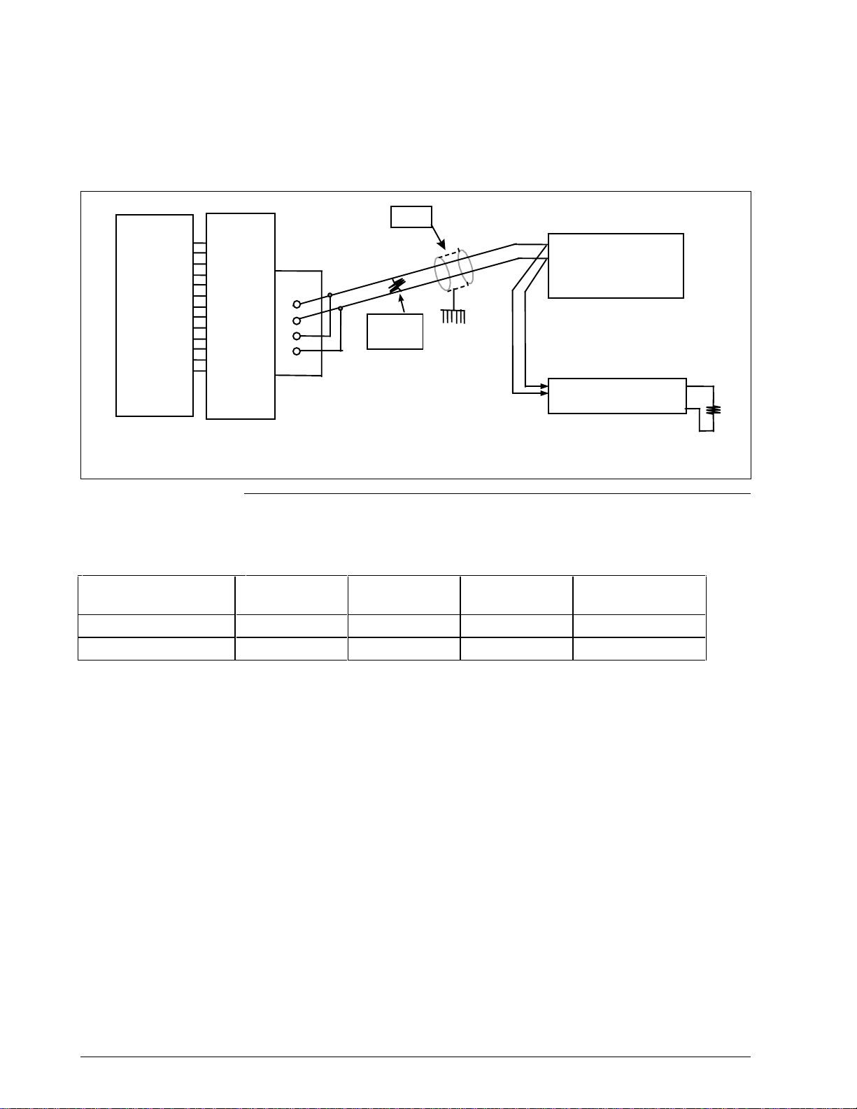
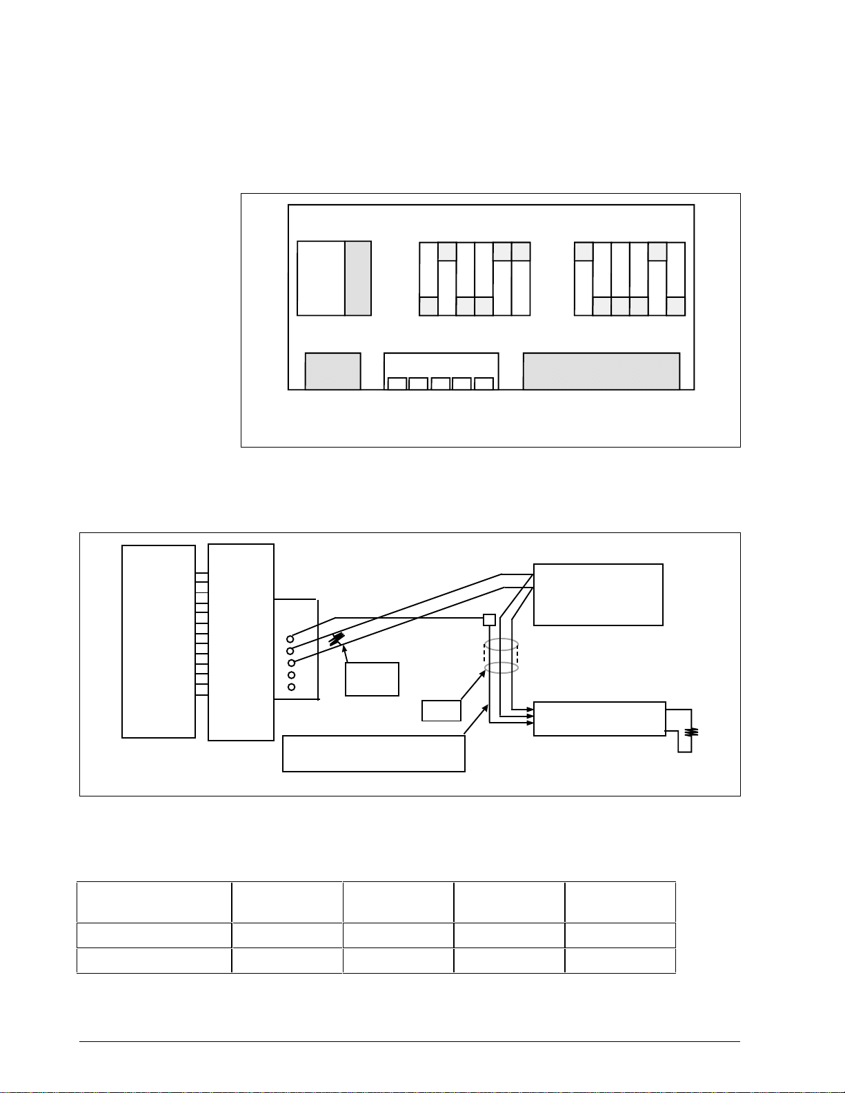
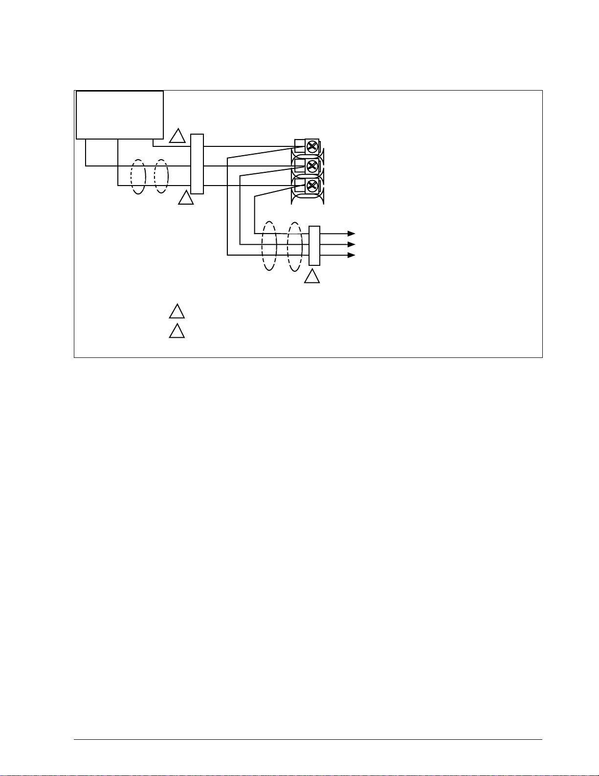
Figure 2-4 UDC3000/3300 Connections
RS422/485
HALF DUPLEX
12
13
14
15
CAUTION
Do not mix half and
full duplex wiring.
SHD
TX+/RX+
TX–/RX–
To Other
Communication
Instruments
(maximum 15)
Master
1
SHD
TX+/RX+
120 Ohm
TX–/RX–
Do not run these
lines in the same
conduit as AC power
120 Ohm Resistor
on Last Leg
Resistor
12
13
14
15
16
17
Use shielded twisted pair cables
1
(Belden 9271 Twinax or equivalent)
RS422/485
FULL DUPLEX
SHD
RX+
RX–
TX+
TX–
Communication
1
To Other
Instruments
(maximum 15)
Master
SHD
TX+
TX–
RX+
RX–
Do not run these
lines in the same
conduit as AC power
120 Ohm Resistor
on Last Leg
120 Ohm
Resistor
120 Ohm
Resistor
24169A
5/99 RS422/485 ASCII Communications Option Product Manual 11
Page 26
2.5 Wiring Diagrams, Continued
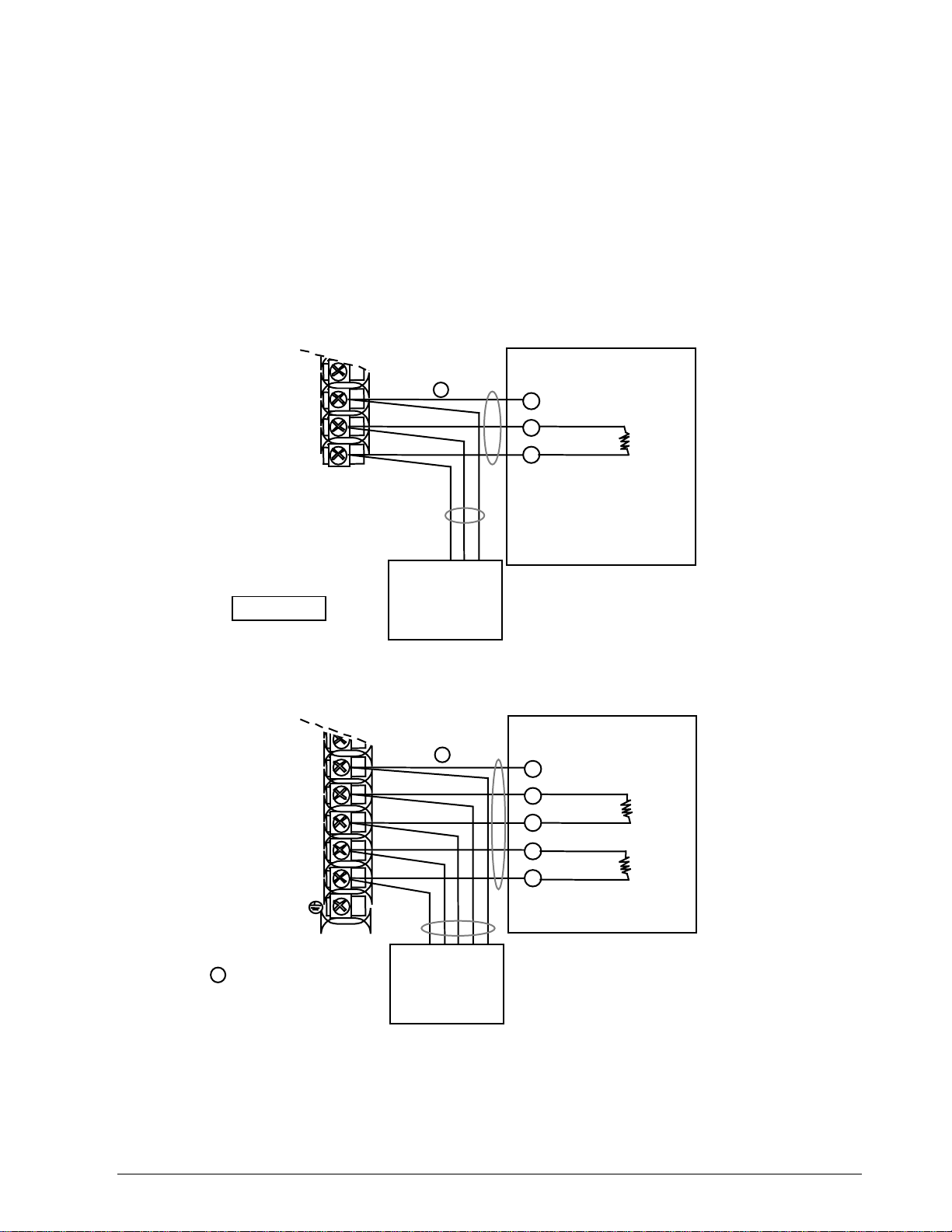
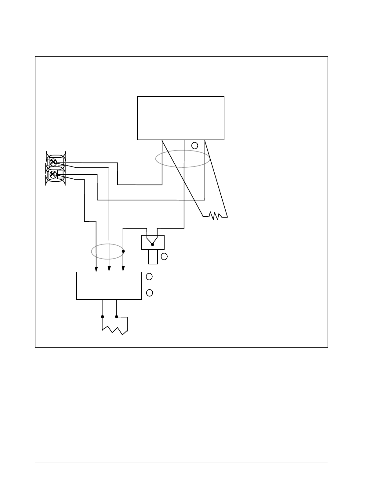
Figure 2-5 UDC6000/6300 Connections
COMMUNICAT ION MASTER
(A) (RTN) (B)
D+
SHLD
21
22
23
D+
D–
D–
2
TO OTHER
COMMUNICATION
CONTROLLERS
D+D–
120 OHMS ON LAST LEG
120 OHMS
1
Connect shield wires together with Honeywell
1
supplied crimp part number 30755381-001
2
Do not run these lines in the same conduit as AC power.
21758A.ppt
12 RS422/485 ASCII Communications Option Product Manual 5/99
Page 27
2.5 Wiring Diagrams, Continued
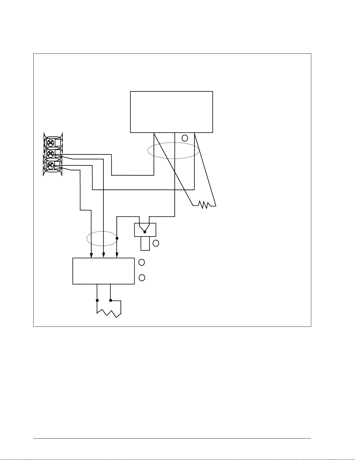
Figure 2-6 UDC5000 Connections (without Digital Input Option)
Communication
Master
D+ SHLD D-
1
11
12
13
2
Optional Communicati on
To Other
Communication
Controllers
4
Do not run these lines in the same conduit as AC power
1
Required for CE Mark Compliance - Kit supplied Part Number
2
51197612-508 contains 8 Ferrite filters
22330A.ppt
5/99 RS422/485 ASCII Communications Option Product Manual 13
Page 28
2.5 Wiring Diagrams, Continued
Figure 2-7 UDC2300 Connections
COMMUNICAT ION MASTER
(A) (RTN) (B)
D+
SHLD
D–
2
13
14
D+
D–
TO OTHER
COMMUNICATION
CONTROLLERS
120 OHMS
1
Connect shield wires together with Honeywell
1
supplied crimp part number 30755381-001
2
Do not run these lines in the same conduit as AC power.
D+D–
120 OHMS ON LAST LEG
21758B.ppt
14 RS422/485 ASCII Communications Option Product Manual 5/99
Page 29

Section 3 – Establishing Communications and Testing
3.1 Preparing the Controller for Communications
Introduction
Synchronization
Configurable
parameters
Each controller on the RS422/485 Communications link must be
configured at the controller level for certain parameters before
communications between the Host and the Controller can be
accomplished.
Before you attempt to exchange messages between your computer and the
controllers on the RS422/485 link, you must set up the controller for the
same form of data transmission that the host computer’s RS422/485
interface uses. This is called Synchronization.
You must match the controller Baud Rate and Parity with that of your
computer.
Table 3-1 is a list of parameters that should be configured, their
definitions, range of settings or selections, the procedure for entering the
information into the controller is found in Table 3-2.
Table 3-1 Communications Parameters
Parameter Definition
Communications
State
Enables or disables the Communication function in the
controller.
Communications
Address
Shed Term used to describe a point in time when the controller,
Shed Time The number selected will represent how many sample
Duplex Selection made for transmission type. Two-wire
TX Delay Configurable response delay timer allows you to force the
This is a number that is assigned to a controller (limited
to 15 controllers) that will be used during
communications. This number will be its address on the
link (address 0-99).
If your controller has two loops, each loop must have its
own individual address (i.e. Loop 1, #6; Loop 2, #7).
which had been working as a slave, reverts to an
independent, stand alone controller using its own inputs,
configuration data and control mode. Shed will happen
when a controller is in slave, the shed is not zero, and the
communication stops.
periods will elapse before the controller sheds from
computer control. Each period equals 1/3 second. 0 = No
shed.
transmission is half duplex. Four-wire transmission is full
duplex.
UDC to delay its response for a time period of from 1 to
500 milliseconds. Compatible with the host system
hardware/software.
5/99 RS422/485 ASCII Communications Option Product Manual 15
Page 30
3.1 Preparing the Controller for Communications, Continued
Parameters,
continued
Table 3-1 Communications Parameters, Continued
Parameter Definition
Shed Controller
Mode and Output
Level
Shed Setpoint
Recall
This selection determines the mode of local control
whenever the controller is SHED from the slave mode.
• Last Mode and Output – The controller will return to
the same mode (Manual or Automatic) and Output
level that it was in before shed.
• Manual Mode, Last Output – The controller will return
to manual mode and the last output level it was in
before shed.
• Manual Mode, Failsafe Output – The controller will
return to manual mode at the output level selected at
ID code 40 – Failsafe Output Value.
• Shed to Automatic Mode – The controller will return to
automatic mode.
This selection determines what setpoint will be used if the
controller is shed from the communications link.
• TO LSP – The controller will use the last local setpoint
stored.
• TO CSP – The controller will store the last computer
setpoint and use it at the Local Setpoint (LSP1, LSP2,
or LSP3, whichever is in use).
Parity Transmitting each ASCII character requires 8 bits:
• 7 bits for the character code
• 1 bit (the eighth) for Parity, which may represent either
ODD or EVEN parity.
Thus, the controller can accommodate your computer's
choice of parity (odd or even) and perform parity checks
on your computer's data transmission. The controller will
return STATUS CODE 04 if it detects incorrect parity.
Baud Rate This is the transmission speed in bits per second. In
order to communicate properly, the controller must be set
to the same Baud Rate as your computer. The Baud
Rate selections are: 300, 600, 1200, 2400, 4800, 9600,
or 19,200.
Communication
Units
Communications
Setpoint Ratio
Communications
Setpoint Bias
This selection determines how the controller values are
expressed during communications:
Percent of span or Engineering units.
Ratio value for computer setpoint. The range is from
-20.00 to +20.00.
Bias value for computer setpoint. The range is from
-999 to 9999.
16 RS422/485 ASCII Communications Option Product Manual 5/99
Page 31

3.1 Preparing the Controller for Communications, Continued
Procedure
The procedure in Table 3-2 tells you what keys to press on the controller
keyboard, the upper and lower display indications, and the range of
settings available to you.
Not all prompts may be available for your particular controller.
Use ▲▼ to make adjustments to the range of setting or selection.
Table 3-2 Controller Procedure for Communication Parameters
Step Press Lower Display Upper Display
Range of Setting
or Selection
1
2
SET
UP
FUNC
COMMUN
successive presses of the [FUNCTION] key will sequentially display all the
functions and their values or selections.
COM STATE DISABLE
DMCS
RS422
ADDRESS 01 to 99*
* Address 00 disconnects it from the
link
Parameter Description
Communication State
Communication Address
(Loop 1)
ADDRESS 2 01 to 99* (must be different
from Loop 1)
* Address 00 disconnects it from the
link
SHED TIME 0 to 255
Sample periods
0 = No Shed will occur
PARITY ODD
EVEN
BAUD RATE 300 4800
600 9600
1200 19200
2400
SHED MODE LAST FAILSAFE
TO MAN TO AUTO
SHED SP TO LSP
TO CSP
DUPLEX HALF
FULL
TX DELAY 1 to 500 milliseconds Transmission Delay
Communication Address
(Loop 2)
Shed Time
Parity
Baud Rate (bits/second)
Controller Shed Mode
and Output Level
Shed Setpoint Recall
Duplex Transmission
Type
Timer
5/99 RS422/485 ASCII Communications Option Product Manual 17
Page 32

3.1 Preparing the Controller for Communications, Continued
Procedure, continued
Table 3-2 Controller Procedure for Communication Parameters, Continued
Step Press Lower Display Upper Display
Range of Setting
or Selection
UNITS PERCENT
ENG UNITS
CSP RATIO –20.00 to +20.00 Commun. SP Ratio
CSP BIAS –999 to +9999 Commun. SP Bias
CSP2 RATIO –20.00 to +20.00 Commun. SP Ratio
CSP2 BIAS –20.00 to +20.00 Commun. SP Bias
3
LOWR
DISP
TO RETURN TO
NORMAL CONTROL
Parameter Description
Communication Units
(Loop 1)
(Loop 1)
(Loop 2)
(Loop 2)
18 RS422/485 ASCII Communications Option Product Manual 5/99
Page 33

3.2 Programming Your Computer
Introduction
Request
Response
Example
To program your computer for communication with the various
controllers on the link, you write input and output statements to send and
receive ASCII character strings to and from the controller. (See ASCII and
Hexadecimal conversion table in Section 12.) You treat the controller like
any I/O device.
To send a request, you program your computer to output the appropriate
character string to the controller.
To get a response, you program your computer to input the expected
character string from the controller.
The following programming statements show how you would output a
request message and read the resulting response. This example is written
in Fortran and uses the following assignments:
• I/O Channel 5 for your computer's RS422/485 Transmit Data Line.
• I/O Channel 6 for your computer's RS422/485 Receive Data Line.
• I/O Channel 7 for your computer's printer or terminal.
Table 3-3 lists the programming statements for this example.
Table 3-3 Programming Statements
Step Statement Action
Sending the
Request
Getting the
Response
Displaying
the
Response
10 Write (5,20)
20 Format (“XXXXXXX”)
30 Read (6,40) Reply
40 Format (12)
50 Write (7,60) Reply
60 Format (12)
Writing the character string the
character string XXXXXXX to I/O
channel 5 which transmits the
character string XXXXXXX to the
controller.
Reading the character string at I/O
Channel 6 which receives data
from the controller into reply.
Writing the contents of Reply to I/O
Channel 7, a printer or terminal.
5/99 RS422/485 ASCII Communications Option Product Manual 19
Page 34

3.3 Message Exchange
What is a message
exchange?
Your computer communicates with the UDC controllers using the
RS422/485 link. Each communication takes place as a message exchange:
Your computer sends a request message (ASCII characters), and then
waits for the resulting response from the controller involved (ASCII
characters). Figure 3-1 shows how this occurs.
Figure 3-1 Message Exchanges
Read request
Host
Host
Response
Write request
Busy
Ready
Status of Last
Transaction
UDC
UDC
23092
Sending requests
Your computer is the host, it initiates a message exchange. The UDC
controllers are respond-only devices.
When you send a Read request, the UDC responds with the data
requested. If you write configuration or override data into a UDC, the
UDC responds with a Busy message (0082xx). The host should send a
Ready message at which time the UDC will respond with a status of the
write transaction. Communication with a single UDC should not be faster
than 1/3 second.
Until the UDC completes processing of the data, any subsequent valid
message received is answered with a busy response.
20 RS422/485 ASCII Communications Option Product Manual 5/99
Page 35

3.4 Request Messages
What is a request
message?
Your computer queries a controller and indicates the communication
function, or operation, that the controller should perform by sending a
request message. Request messages are composed of standard fields,
separated by commas. Each field contains a certain kind of information,
which you must enter in order to have a valid request message.
Request message
fields
Figure 3-2 shows the request message fields and the selections that may be
entered into each field. Table 3-4 lists these selections and their
definitions.
Figure 3-2 Request Message Fields
,,,, ,
Station
Address
A two digit device
address – 01 to 99
NOTE: Two loop
controllers will have an
address assigned to
each loop. Specify the
specific address for the
loop with which you
want to communicate.
Comma
Delimiter
required to separate fields
Protocol Field
4204 –
selects checksum
protocol
0204 –
ignores checksum
UDC Status (hexadecimal)—see matrix below
– REQUEST –
=
Single Byte Decimal – unsigned (digital configuration list) – for
11
Parameter codes 128 to 255
=
Single Byte Decimal – unsigned (extended
41
list) – for Parameter codes 128 to 158 in extended configuration
Oxford Floating Point (analog configuration list) – for Parameter
=
18
codes 001 to 125
Oxford Floating Point (extended
=
48
Parameter codes 001 to 021 in extended configuration
ASCII Text (Loopback only)
=
DD
ASCII Text (Analog configuration list for parameter
=
I D
I D Code #103 - Totalizer value (UDC6300, UDC 3300 only)
Data Type Field
CR LF
Checksum Field
HH=2-digit Hex
representing
Data Field
READ – Item no. only
WRITE – Item no., value
READY – 000
LOOPBACK – ASCII text
analog configuration list) – for
calculated checksum
digital configuration
UDC State and Mode
0 = Slave, Manual
2 = Slave, Toggle between LSP/RSP*
4 = Slave, Automatic
6 = Slave, No Change
E = Monitor, No Change
Change from RSP to LSP or LSP to RSP
*
READ only in Monitor Mode
**
READ and WRITE in Control Mode
Used after WRITE to verify data transaction
***
Protocol Class and Operation Code
4 = Configuration, Read**
5 = Configuration, Write**
6 = Configuration, Ready*** (only E6)
8 = Loopback (only E8)
P
r
o
t
o
c
Mode
SLAVE
MAN
SLAVE
TOGGLE
SLAVE
AUTO
SLAVE
NO CHNG
MON
NO CHNG
CONF
o
l
READ
00000100 00000101 00000110
04 05 06 X
00100100 00100101 00100110
24 25 26 X
01000100 01000101 01000110
44 45 46 X
01100100 01100101 01100110
64 65 66 68
11100100 11100110
CONF
WRITE
E4 X E6 E8
CONF
READY
LOOP
BACK
23083
5/99 RS422/485 ASCII Communications Option Product Manual 21
Page 36

3.4 Request Messages, Continued
Request message
field selections
Table 3-4 is a list of selections for the request message fields and their
definitions.
Table 3-4 Request Message Fields Definitions
Selection Definition
Station Address A two digit device address – from 01 to 99 – that
identifies the specific controller you are addressing. You
must assign a unique station address to each controller
on the link.
For a 2 Loop controller, two distinct addresses must be
configured. One address is used to designate Loop 1;
and one is used to designate Loop 2. Either address may
be used for transactions which are loop independent.
See "Preparing the Controller for Communications" in this
manual. A UDC will not respond to address 0 since the
address results in a disconnect.
Protocol Field A four digit number that selects whether or not you are
going to use a Checksum Protocol (for increased data
security) with your message exchange.
• 4204 selects Checksum Protocol
– see “Checksum Protocol”
UDC State and
Mode
Protocol Class and
Operation Code
• 0204 ignores Checksum Protocol
Any sequence utilizing other than 4 or 0 in the first digit
results in an error with an error message returned.
A hexadecimal number that determines what state you
want the UDC to be in (monitor or slave) and the mode of
operation desired (manual or automatic). You can also
change the controller setpoint from Local setpoint to
Remote setpoint or vice-versa.
ATTENTION
mode will not be indicated in the response until the next
transaction.
A hexadecimal number that allows you to do a Loopback
or do a READ, WRITE, or READY transaction.
Any change made in UDC State or Control
22 RS422/485 ASCII Communications Option Product Manual 5/99
Page 37

3.4 Request Messages, Continued
Request message
field selections,
continued
Table 3-4 Request Message Fields Definitions, Continued
Selection Definition
Data Type Field A two digit number that specifies the format, or data type,
of each of the parameters that can be accessed in the
UDC controller.
11 = Single Byte Decimal (unsigned) – used with
configuration protocol for digital parameter code
numbers 128 through 255.
41 = Single Byte Decimal (unsigned) – used with
configuration protocol of extended digital
parameter code numbers.
18 = Floating Point Format – used with configuration
protocol for analog parameters code numbers 001
through 125.
48 = Floating Point Format – used with configuration
protocol for extended analog parameter code
numbers.
DD = ASCII Text – Used with loopback protocol only.
I D = ASCII Text – Used with configuration protocol for
Analog Parameters ID Code #103 |
(UDC 6300, UDC 3300 only)
Data Field The data in this field is determined by the type of request:
• READ – three digit parameter code which identifies a
particular parameter for which you want to know the
value or selection.
• WRITE – three digit parameter code, which identifies a
particular parameter you want to change, a comma (,),
and the value or selection you want to enter.
• READY – three zero's (000) – used in conjunction with
a write request. Sent after a write request to verify that
the information transmitted was received.
• LOOPBACK – ASCII Text
Checksum Field
(Optional)
Carriage
Return/Line Feed
This field is a one byte hexadecimal value (two ASCII
characters) representing the binary sum, ignoring carries,
generated by adding the ASCII code for each character
in the message exchange, up to but not including the
checksum and the CR and LF characters.
• No Characters = No Checksum
• HH = two digit hexadecimal number representing the
calculated checksum
Terminates a message. The message will not be
exchanged unless used in this order (CR LF).
5/99 RS422/485 ASCII Communications Option Product Manual 23
Page 38

3.5 Response Messages
What is a response
message?
The response message tells your computer the present status of the
operation initiated by the request message. Response messages are
composed of standard fields, separated by commas.
Response message
fields
Each field contains a certain kind of information. Figure 3-3 indicates the
response message fields and lists the information that could be returned in
each field.
Figure 3-3 Response Message Fields Information
– RESPONSE –
,,
Request Message Status Code
00 =
Request message received successfully
01 =
Data Type Code invalid
02 =
Request is invalid
04 =
Checksum protocol indicates a problem or a
parity error
UDC Status Code
UDC functioning properly and has performed the
00 =
operation
UDC received invalid data and aborted the operation
01 =
UDC is busy (Ret'd on WRITES)*
02 =
UDC cannot perform requested operation in current
04 =
mode
UDC performing Autotune or Accutune
06 =
UDC unable to perform request at present time (may
07 =
occur during writes to EEProm or when unit is in set up)
UDC error status has changed (device dependent status)
80 =
Added to above i.e. –82
UDC State and Mode (Hexadecimal No.)
0 = Slave, Manual LSP
2 = Slave, Manual RSP
4 = Slave, Automatic LSP
6 = Slave, Auto RSP
* **To verify what you have sent, send a READY request (see READ/WRITE operations.
Change of state = Alarm went ON or OFF since last communication.
8 = Monitor, Manual LSP
A = Monitor, Manual RSP
C = Monitor, Automatic LSP
E = Monitor, Automatic RSP
item #, value
Checksum
returned for 4204
–
requests
not returned for 0204
Data Field
always item no., value
(integer or floating point)
Alarm Status (Hexadecimal No.)
No Alarm
=
0
Alarm #1 On
=
1
Alarm #1 Change of state** (Note 1)
=
2
Alarm #1 On, Alarm #1 Change of state
=
3
Alarm #2 On
=
4
Alarm #1 On, Alarm #2 On
=
5
Alarm #1 Change of state, Alarm #2 On
=
6
Alarm #1 & #2 On, Alarm #1 Change of state
=
7
Alarm #2 Change of state (Note 1)
=
8
Alarm #2 Change of state, Alarm #1 On
=
9
Alarm #1 & #2 Change of state (Note 1)
=
A
Alarm #1 & #2 Change of state, Alarm #1 On
=
B
Alarm #2 Change of state, Alarm #2 On
=
C
Alarm #1 & #2 On, Alarm #2 Change of state
=
D
Alarm #2 On, Alarm #1 & #2 Change of state
=
E
Alarm #1 & #2 On, Alarm #1 & #2 Changed
=
F
Note 1. On the UDC6300, If alarm 3 and 4 are enabled,
then:
2 = Alarm 3 ON
8 = Alarm 4 ON
A = Alarm 3 and 4 ON
–
requests
23084
24 RS422/485 ASCII Communications Option Product Manual 5/99
Page 39

3.5 Response Messages, Continued
Response message
field Information
Table 3-5 is a list of the information contained in the response message
and their definitions.
Table 3-5 Response Message Fields Definitions
Type of
Information
Request Message
Status Code
UDC Status Code A two digit code that indicates whether or not the UDC
UDC State and
Mode
A two digit code that indicates whether or not the present
request message was successfully processed. For
detailed explanations and recovery procedures for these
codes, refer to ‘Request Message Status Codes” in this
section.
controller addressed is working correctly and has
performed the requested operation. For detailed
explanations and recovery procedures for these codes,
refer to “UDC Status Codes” in this sections.
A hexadecimal number that indicates whether the UDC
controller's present state is "Slave" or "Monitor" and
whether it is in Manual or Automatic mode using the
Local setpoint or Remote setpoint.
ATTENTION
mode will not be indicated in the response until the next
transaction.
Any change made in UDC State or Control
Definition
Alarm Status A hexadecimal number that indicates the status of Alarm
#1 and #2 or both. It indicates when the Alarm is on or
has changed state since last communication. The change
of state indicator is a backup to the on/off state indicator.
If an alarm goes from off to on then off in between
consecutive communications, the on/off would not show
it. The change of state flag would show that it had
happened.
Data Field This field always returns the identifying number for the
parameter in the request message and the value for that
parameter (either an integer or field floating decimal
point).
Optional
Checksum Field
This field is a one byte hexadecimal value (two ASCII
characters) representing the binary sum, ignoring carries,
generated by adding the ASCII code for each character
of the response message, ignoring parity, up to but not
including the checksum. It is returned for 4204 requests
only. See “Checksum Protocol” in this section.
5/99 RS422/485 ASCII Communications Option Product Manual 25
Page 40

3.6 Status Codes
Request message
status codes
The codes, listed in Table 3-6, indicate whether or not the request message
was successfully processed. A suggested recovery procedure is listed for
those that indicate an error.
Table 3-6 Request Message Status Codes
Request
Message
Status Code
00 The request message was
successfully processed.
01 Request message format
invalid.
02 Request is invalid. The
controller addressed does not
support the requested
operation.
04 Checksum indicated in the
request message differs from
the checksum the UDC
calculated. Or UDC has
detected incorrect parity for
character transmitted in
request.
Explanation Suggested Recovery
Not applicable.
Check format of request
message. Re-send message.
Check parameter identifying
code and value.
Check checksum calculations.
Re-send message.
26 RS422/485 ASCII Communications Option Product Manual 5/99
Page 41

3.6 Status Codes, Continued
UDC status codes
All the controllers on the link return the UDC Status Codes listed in
Table 3-7. A suggested recovery procedure is listed for those that indicate
an error.
Table 3-7 UDC Status Codes
UDC
Status
Code
00 UDC functioning properly and
has received the message
correctly.
01 UDC has received invalid data
from the computer and did not
perform the requested
operation.
02 UDC is busy until the data
received is processed.
04 UDC cannot perform the
requested operation in its
current mode.
Explanation Example Suggested Recovery
Data error: Configuration item
number incorrect, data out-ofrange or incorrect.
Returned after each write
when a controller is
processing a change to
configuration database.
1. Request error, request
illegal, request incorrect in
present state (Calib).
2. Requested illegal mode
change.
3. Data received in wrong
format.
Not applicable.
Check the UDC’s configuration
and limits.
1. Do ready request to see if
information received.
2. Wait, then re-send
request.
Check configuration with last
request. Check data field and
data type field.
06 The UDC is performing
Autotune or Adaptive Tune.
07 UDC unable to perform
request at present time.
+80 UDC status change Indicates one or more of the
*Emergency manual, Failsafe, Working calibration checksum error, Configuration checksum error, Factory calibration
error, Hardware failure, Restart after shed, Configuration/calibration memory changed.
Returned when the controller
is performing the Autotune or
Adaptive Tune function.
May occur during writes to
EEPROM or when unit is in
set up and data changing via
the keyboard.
following have changed.*
Wait or stop Autotune/
Adaptive Tune, then re-send
message.
Wait, re-send request.
Read 255 code. Clear by
writing to 255 code.
5/99 RS422/485 ASCII Communications Option Product Manual 27
Page 42

3.7 Checksum Protocol (for Data Security)
Introduction
CAUTION
Using checksum
protocol
The optional Checksum Protocol is used to increase security on the
RS422/485 link. This protocol enables both your computer and your UDC
to detect messages that the RS422/485 link has transmitted inaccurately.
Thus, this protocol makes the RS422/485 communications link more
reliable.
Failure to use checksum protocol could make the undetected error rate for
the RS422/485 link unacceptable for your process control application.
You can use the checksum protocol with any message exchange. The
UDC uses the protocol to check the transmission of request messages.
Your computer uses the protocol to check the transmission of response
messages.
When a message exchange includes checksum protocol:
• Your UDC can tell, with high probability, if the ASCII code in the
request message has changed during transmission from your computer.
• Your computer can tell, with high probability, if the ASCII code in the
response message has changed during transmission from the UDC.
To use Checksum Protocol, you change the format of the request message
as shown in Figure 3-4 as follows:
• You use a 4204 in the request format.
• You insert a 2-digit Hexadecimal number that represents the checksum
that you have calculated from the ASCII codes in the request message
as explained in “Calculating the Checksum”. See Section 12 for an
ASCII Conversion table and a Hexadecimal Binary table.
Figure 3-4 Request Format for Checksum Protocol
ASCII code for these characters is added
to calculate the checksum
,
Address
Protocol Field
UDC Status
Data Type Field
Operation Dependent Data
CHECKSUM
Carriage Return
Line Feed
,,
,
,
CR LF42 04
23085
28 RS422/485 ASCII Communications Option Product Manual 5/99
Page 43

3.7 Checksum Protocol (for Data Security), Continued
Calculating the
Checksum
Table 3-8 lists the procedure for calculating the checksum. See Figure 3-5
for an example.
Table 3-8 Calculating the Checksum Procedure
Step Action
1 Take the binary sum, ignoring carries generated by the most
significant bits, of the ASCII code for each of the message’s
characters, ignoring parity, up to but not including the CHECKSUM
field and the CR and LF characters. The final sum should be an 8-bit
binary number. See Section 12 for ASCII Conversion table and
Hexadecimal to Binary table.
2 Convert the four least significant bits of this sum to the equivalent
hexadecimal digit. This becomes the least significant digit in the
CHECKSUM field.
3 Convert the four most significant bits of this sum to the equivalent
hexadecimal digit. This becomes the most significant digit in the
checksum field.
5/99 RS422/485 ASCII Communications Option Product Manual 29
Page 44

3.7 Checksum Protocol (for Data Security), Continued
Checksum calculation
example
Figure 3-5 shows an example of the result of a checksum calculation
according to instructions in Table 3-8.
Figure 3-5 Example of Checksum Calculation
Example
03,4204,E4,18,001,7C CR LF
0
3
,
4
2
0
4
,
E
4
,
1
8
,
0
0
1
,
0011
0011
0110
0010
1000
0011
1100
0011
1111
0011
0010
0011
0101
0010
1000
0100
1100
0011
1111
0010
0010
0011
0101
0010
1001
0010
1011
0011
1110
0011
0001
0011
0101
0010
0111
0000
0011
0011
1100
1111
0100
0011
0010
0101
0000
0101
0100
1001
1100
0101
0101
1010
0100
1110
1100
1010
0001
1011
1000
0011
1100
1111
0000
1111
0000
1111
0001
0000
1100
1100
Hex ➔
30 RS422/485 ASCII Communications Option Product Manual 5/99
7
C (Checksum)
23086
Page 45

3.7 Checksum Protocol (for Data Security), Continued
Success or failure
After receiving a request that uses checksum protocol, the UDC calculates
the checksum of the characters received and compares this to the
hexadecimal number stated in the checksum field. Depending on whether
the checksums agree, the UDC returns either the “success” or “failure”
response. Figure 3-6 indicates what happens when checksum protocol
is used.
Figure 3-6 Using Checksum Protocol
Request that includes
Host UDC
Checksum protocol
"Failure" response
"Success" response
Computer uses
protocol to check
response messages
Controller uses
23087
protocol to check
request messages
5/99 RS422/485 ASCII Communications Option Product Manual 31
Page 46

3.7 Checksum Protocol (for Data Security), Continued
Success response
If the checksums agree – and no other problems are encountered – the
UDC returns the success response beginning with Request Message Status
Code 00. Figure 3-7 indicates this response.
Figure 3-7 “Success Response” Message Fields
"success" response
0 0 CR LF
Request Message
Status Code
UDC Status Code
UDC State and Mode
Alarm Status
Operation Dependent Data
CHECKSUM
Carriage Return
Line Feed
,,
23088
32 RS422/485 ASCII Communications Option Product Manual 5/99
Page 47

3.7 Checksum Protocol (for Data Security), Continued
Failure response
If the checksums disagree, UDC ignores the request and returns the failure
response Request Message Status Code 04. To recover, your computer
repeats the operation. Figure 3-8 indicates this response.
Figure 3-8 “Failure Response” Message Fields
"failure" response
Request Message Status Code
(checksum protocol indicates a problem or parity error)
The failure response may also show that there is a problem with the UDC.
In this case, the response would be:
Request message status code (CHECKSUM O.K.)
UDC Status Code (01 through 07 indicating an error)
UDC State and Mode
Alarm Status
Checksum (for the 4 previous characters)
04
00 CR LF
CR LF
23089
Checksum Calculation
ATTENTION
After receiving a response that has checksum protocol, your computer
should perform the checksum calculations on the characters received, and
compare the results to the checksum in the response message. If the
checksums disagree, your computer should repeat the operation.
If there is a problem with the UDC itself, a UDC Status Code indicating
an error will be returned.
5/99 RS422/485 ASCII Communications Option Product Manual 33
Page 48

3.8 Shed
What is Shed?
Shed time
Shed controller mode
and output level
Shed setpoint recall
Shed happens when the controller, which has been working in "Slave,"
reverts to "Stand Alone" mode. Upon receiving a "Slave" message, the
controller resets the "SHED TIMER." If this timer expires before the next
valid message, the controller goes to stand alone operation. When the host
reconnects with a valid message, the response will indicate as 8 at the
third digit to indicate a restart after shed.
Thus SHED acts as a safeguard in case the computer or communications
link fail. If something prevents the computer from communicating with
the controller the device returns to the local control mode. The local
operator is then able to regain control over the controller and operate it by
the keyboard.
Shed Time works like a timer. The number selected will represent how
many sample periods there will be before the controller sheds from
computer control. You can configure the shed time to be one that is
between 1/3 second and approximately 83 seconds. 0 = No Shed.
This determines the mode of local control whenever the controller is shed
from the communication link.
This determines what setpoint will be used if the controller is shed from
the communications link.
How to enter this
information
Refer to “Preparing the Controller for Communications” in this section for
these selections and procedure for entering the information into the
controller.
34 RS422/485 ASCII Communications Option Product Manual 5/99
Page 49

3.9 Loopback (UDC 2300, UDC 3000, UDC 3300 Only)
Making sure all the
UDC 2300/3000/3300
controllers are on-line
Loopback message
exchange
Request message
Once you have established communications between the UDC
2300/3000/3300 controller and your computer and understand the message
exchange, it is a good idea to test communications to all the controllers on
the RS422/485 link. The LOOPBACK operation is an easy way to do this.
By including the appropriate address in the loopback operation, you can
send a series of characters from your computer to any device on the link.
After receiving these characters, the device addressed "echoes" back the
same characters. By comparing the characters sent to those returned, you
can tell whether communications are working correctly.
With this message exchange, you can test the communication link
between your computer and any controller.
• In the request message, your computer sends a series of characters to
the desired device.
• In the response message, the device returns the characters it received to
your computer.
Table 3-9 is an example of the Loopback Request Message with or
without the checksum.
Table 3-9 Example of Loopback Request Message
Protocol Message Format
With Checksum AA,4204,E8,DD,123456789ABC,CS CR LF
(12 characters max.)
Without Checksum AA,0204,E8,DD,123456789ABCDE, CR LF
(14 characters max.)
Where:
AA = Status Address
5/99 RS422/485 ASCII Communications Option Product Manual 35
Page 50

3.9 Loopback, Continued
Response message
Programming
example
Table 3-10 is an example of the Loopback Response Message with or
without the checksum.
Table 3-10 Example of Loopback Response Message
Protocol Message Format
With Checksum OOSSMA,123456789ABC,CS CR LF
Without Checksum OOSSMA,123456789ABCDE, CR LF
Where:
OO = UDC Type Error
SS = UDC Status
M=Mode (Hex – see "Message Exchange")
A = Alarm Data (Hex – see "Message
Exchange")
The programming statements in Table 3-11 show how you could perform
the LOOPBACK operation with the UDC controller that has station
address 09– not using checksum.
If the LOOPBACK operation is successful, these statements would print
OOOOMA,HELLO#09.
Where: M = Mode
A = Alarm Data
Table 3-11 Programming Example
Programming Statement Result
Request 10 Write
20 Format
(
"09,0204,E8,DD,HELLO#09")
Response 30 Read (6,40) Reply
40 Format (A15)
50 Write (7,60) Reply
60 Format (A15)
(5,20)
Sending the
LOOPBACK request
message that contains
the eight characters
HELLO#09 to the
controller with station
address 09.
Receiving and printing
the response message
that contains the
characters returned.
36 RS422/485 ASCII Communications Option Product Manual 5/99
Page 51
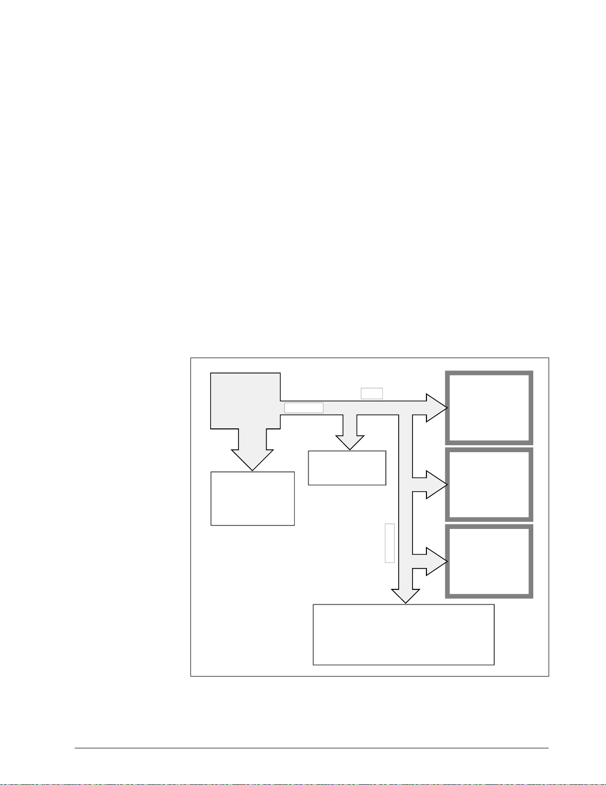
3.10 Recovering from Communications Failures
What is a lost
message?
What happens to a
lost message
When your computer sends a request message but doesn’t receive a
response, a message (either the request or the response) has been lost on
the link. As shown in Figure 3-9, problems in your computer, the link, or
the controller could cause a message to get lost.
Depending on how your programming handles messages, a lost message
could hang up your programming forever. Suppose your programming
uses a high-level language input command (in Fortran, READ) to retrieve
response messages from the input device or buffer fed by the link. Upon
executing this input command, your computer goes to the input device to
retrieve the response message and waits there until the data arrives. If a
message is lost, the message exchange is never completed. Thus, the input
command is left waiting for a response message that will never arrive.
As you can see, you must design your programming to handle the
possibility that the messages will get lost on the link. Make sure that your
programming includes a timing routine that detects the lost message and
aborts the pending input command.
Figure 3-9 Lost Messages
Computer
executes
routine to send
request
message
A problem in your
computer or the RS
interface stops the
transmission of data
on the RS links
REQUEST
A problem in the RS
link stops the
transmission of data
Controllers can't process the request because –
• Your computer has changed Baud rate or parity.
Therefore, the controller is synchronized for data
transmissions different from those your computer
is now using.
• Controller is not operational.
LINK
Controller
Controller
L
I
N
K
Controller
23090
5/99 RS422/485 ASCII Communications Option Product Manual 37
Page 52

3.10 Recovering from Communications Failures, Continued
Timing message
exchanges to detect
lost messages
The flowchart in Figure 3-10 shows how to time a message exchange so
that you can tell if a message has been lost. (This is only an example, not
the suggested method.) Like all timing routines, this one includes a wait
and a read interrupt (in Basic, a PEEK) rather than a standard input
command.
Figure 3-10 Timing a Message Exchange and Checking for a Response
Send the request message.
Wait the appropriate amount of time
On time out, check for the response message.
If controller has not responded,
If controller has responded,
process response message.
retry failed request three times. If
no response, refer to Loopback
instructions.
PROGRAMMING A TIMED MESSAGE EXCHANGE
Longest Request/Response Time
in mSec:
(78 × [19,200/Baud] mSec
PLUS (+)
Wait Time:
35 mSec (includes leeway)
Average Time to Execute Timer
Loop:
1 millisecond
Baud Time
19,200
9600
4800
2400
1200
600
300
113 ms
191 ms
347 ms
659 ms
1283 ms
2531 ms
5027 ms
Send request.
X = X + 1
X = Time
YES
Check input device.
Response
YES
Process response
NO
NO
Request
3 times
YES
See Loopback instructions.
NO
23091
38 RS422/485 ASCII Communications Option Product Manual 5/99
Page 53

3.10 Recovering from Communications Failures, Continued
Wait
Read Interrupt
How long to wait
Timing routine
The WAIT is the amount of time that your computer will wait for a
response before assuming that a message has been lost. If the response
doesn’t appear in the allotted time, your computer should retry the request
– up to three times. If your computer still hasn't gotten a response, your
programming assumes that communications on the link have failed and
calls the recovery or alarm routine.
The READ interrupt merely checks that input device or buffer for data,
instead of waiting indefinitely until data arrives.
Before you can program a timing routine, you must determine how long to
wait for a response. This wait must be at least as long as the response time
for the longest message exchange when executed at your computer's baud
rate. Also note that after the UDC has completed sending a response to
your computer, it will require up to 1/3 second of additional processing
time before it is ready to accept any new request message. If your
computer sends a request to the UDC while it is still busy processing the
previous request, it will respond with a BUSY status. Your computer can
handle this situation by re-trying the request.
Once you have established the appropriate wait time, you can program the
timing routine. To do so, you loop an instruction until the desired wait
time has elapsed, as shown in the figure on the previous page.
This timing routine is the simplest one you could program. But, it is not
efficient – your program waits the same amount of time for the shortest
message as the longest. You devise a more efficient routine, such as a loop
that checks for the response message each time "X" increments.
5/99 RS422/485 ASCII Communications Option Product Manual 39
Page 54

40 RS422/485 ASCII Communications Option Product Manual 5/99
Page 55

Section 4 – Read and Write Operations
4.1 Read Operations
Introduction
Transaction states
Analog or digital
The Read operations (Data Retrieval) allow your computer to read data
from any controller on the RS422/485 link. Data retrieval for each
operation is accomplished through a message exchange between your
computer and the device you are addressing.
You can request the data for only one identifying code at a time, but, the
response may be a single variable or a three variable type depending on
the code used.
Read transactions can be performed in either UDC state: Monitor or Slave.
ATTENTION
Any change made in UDC state or control mode will not be
indicated in the response until the next transaction.
The parameters being read will be either Analog (codes 1 through 125) or
Digital (Codes 128 through 255) value or selections so that all Read
message formats must adhere to the standardization rules shown in the
tables that follow.
5/99 RS422/485 ASCII Communications Option Product Manual 41
Page 56

4.2 Read Analog Parameters
Introduction
Request format
The Analog identifying Codes are codes 001 through 125. Each of these
codes are read using the Request and Response formats shown in tables
4-1 and 4-2.
Table 4-1 lists the request format with or without checksum, for Analog
I.D. Codes 001 through 125.
Where:
AA = Station Address (Each loop of a 2-loop controller has a
unique address – see "Message Exchange")
X = UDC State and Mode (Hex – see "Message Exchange")
NNN = Identifying Code for Analog Parameter (001 to 125)
CS = Checksum Value (2 digit hex – see "Checksum")
CR = Carriage Return
LF = Line Feed
Table 4-1 Analog Parameter Request Format
Format Type Format
With Checksum AA, 4204, X4, 18*, NNN, 0, CS CR LF
Without Checksum AA, 0204, X4, 18*, NNN, 0, CR LF
*Use 48 for extended anal og configuration I.D. codes (001 to 043), UDC 3300,
UDC 6000, UDC 6300 only.
42 RS422/485 ASCII Communications Option Product Manual 5/99
Page 57

4.2 Read Analog Parameters, Continued
Response format
Table 4-2 lists the response format, single or three variable with or
without checksum, for Analog I.D. Codes 1 through 125.
Where:
OO = UDC Type Error (00 = No Error)
SS = UDC Status
M=Mode (Hex – see "Message Exchange")
A = Alarm Data (Hex – see "Message Exchange")
NNN = Identifying Code for Analog Parameter
DDD.D = Floating Point Value
CS = Checksum (two digit hex – see "Checksum")
CR = Carriage Return
LF = Line Feed
Table 4-2 Analog Parameter Response Format
Variable Format Type Format
Single with checksum OOSSMA, NNN, DDD.D, CS, CR LF
(see note 1)
without checksum OOSSMA, NNN, DDD.D, CR LF
(see note 1)
Three with checksum OOSSMA, NNN, DDD.D, DDDD, DDD.D, CS,
CR LF
(see note 1)
without checksum OOSSMA, NNN, DDD.D, DDD.D, DDDD.,CR
LF
(see note 1)
Note 1.Floating point values may look like this:
DDDD. DDD.D DD.DD D.DDD
-DDD.D -DDD. -DD.DD -D.DDD
They must have four characters and one decimal point as shown, negative
sign as an extra character.
5/99 RS422/485 ASCII Communications Option Product Manual 43
Page 58

4.2 Read Analog Parameters, Continued
Example
Figure 4-1 is an example of a Read Analog Parameter message exchange;
specifically, Read the value of heat gain; Analog I.D. Code 001.
Figure 4-1 Read Analog Parameter Message Exchange
request
Address
Protocol Field (without checksum)
UDC State and Mode
E = monitor, no change
4 = configuration, read
Data Type Code for Analog
Identifying Code for Heat Gain
Place Holder for Data Values
response
No UDC Error
No Change in Status
Monitor
No Alarm
Heat Gain Identifying Code
Value of Heat Gain
03 , 0204 , E4 , 18 , 001 ,
00 00 C0 , 001 , 005.0 CR LF
0,
CR LF
23093
44 RS422/485 ASCII Communications Option Product Manual 5/99
Page 59

4.3 Read Digital Parameters
Introduction
Request format
The Digital identifying codes are Codes 128 through 255. Each of these
codes are read using the Request and Response formats shown in Tables
4-3 and 4-4.
Table 4-3 lists the request format, with or without checksum, for digital
I.D. Codes 128 through 255.
Where:
AA = Station Address (Each loop of a 2 loop controller has a
unique address – see "Message Exchange")
X = UDC State and Mode (Hex – see "Message Exchange")
MMM = Identifying Code for Digital Parameter (128 to 255)
CS = Checksum Value (two digit hex – see "Checksum")
CR = Carriage Return
LF = Line Feed
Table 4-3 Digital Parameter Request Format
Format Type Format
With Checksum AA, 4204, X4, 11*, MMM, 0, CS, CR LF
Without Checksum AA, 0204, X4, 11*, MMM, 0, CR LF
*Use 41 for extended digital configuration I.D. codes (128 to 158), UDC 3300,
UDC 6000, UDC 6300 only.
5/99 RS422/485 ASCII Communications Option Product Manual 45
Page 60

4.3 Read Digital Parameters, Continued
Response format
Table 4-4 lists the response format, with or without checksum, for digital
I.D. codes 128 through 255.
Where:
OO = UDC Type Error (00 = No Error)
SS = UDC Status
M=Mode (Hex – see "Message Exchange")
A = Alarm Data (Hex – see "Message Exchange")
MMM = Identifying Code for Digital Parameter
DDD = Digital Value (always 3 characters)
CS = Checksum (2 digit hex – see "Checksum")
CR = Carriage Return
LF = Line Feed
Table 4-4 Digital Parameter Response Format
Format Type Format
With Checksum OOSSMA, MMM, DDD, CS CR LF
Without Checksum OOSSMA, MMM, DDD, CR LF
Example
Figure 4-2 is an example of a Read Digital Parameter message exchange;
specifically, read the algorithm selection: digital I.D. Code 128 and
maintain or change the UDC state to slave.
Figure 4-2 Read Digital Parameter Message Exchange
request
Address
Protocol Field (without checksum)
UDC State and Mode
6 = slave, no change in mode
4 = configuration, read
Data Type Code for Digital
Identifying Code for Algorithm Selection
Placeholder for Data Value
response
No UDC Error
No Change in Status
Monitor
No Alarm
Algorithm Selection Identifying Code
PID-B
NOTE: Change to slave will not be noted until the next message exchange.
0
03 , 0204 , 64 , 11 , 128 , CR LF
00 80 C0 , 128 , 002 CR LF
,
23094
46 RS422/485 ASCII Communications Option Product Manual 5/99
Page 61

4.4 Write Operations
Introduction
Transaction state
Write message
exchange
The Write operations allow your computer to write data type transactions
such as Overriding the PV, Setpoint, inputs as well as writing
configuration data such as Tuning Parameters, Algorithm Selection,
Setpoint Ramp Information, etc. to the controller.
Write transactions can only be performed in the Slave Mode.
In a Write transaction, only single items are permitted to be written.
A Ready transaction is required to determine if the information was
received.
Following any Write, a Busy indication is returned.
Table 4-5 lists the steps for the Write message exchange.
Table 4-5 Write Message Exchange Steps
Step Action
1 Do a Write request to change a parameter (see Table 4- 6).
2 Receive a Busy response (see Table 4-7).
CAUTION
ATTENTION
3 Send Ready request to see if the information has been processed
(see Table 4-8 ).
4 Receive an “Is Ready” response (see Table 4-9 ).
5 Do a Read request to check the value (OPTIONAL).
The data stored in non-volatile memory is expected to be retained for 10
years. However, additional writes will degrade the retentivity of the
non-volatile memory.
Any change made in UDC State or Control Mode will not be indicated in
the response until the next transaction.
5/99 RS422/485 ASCII Communications Option Product Manual 47
Page 62

4.5 Write Analog Parameters
Introduction
Request format
The analog identifying codes are codes 001 through 125. The Write
request and response formats are shown in Tables 4-6, 4-7, 4-8, and 4-9.
Table 4-6 lists the write request format with or without checksum for
Analog I.D. Codes 1 through 125.
Where:
AA = Station Address (Each loop of a 2 loop controller has a
unique address – see "Message Exchange")
X = UDC State and Mode (Hex – see "Message Exchange")
NNN = Identifying Code for Analog Parameter (001 to 125)
DDD.D = Floating Point Value (see note 1)
CS = Checksum Value (two digit hex – see "Checksum")
CR = Carriage Return
LF = Line Feed
Table 4-6 Write Request Format for Analog I.D. Codes
Format Type Format
With Checksum AA, 4204, X5, 18*, NNN, DDD.D, CS CR LF (see note 1)
Without Checksum AA 0204, X5, 18*, NNN, DDD.D, CR LF (see note 1)
*Use 48 for extended anal og I.D. codes 001 through 043, UDC 3300, UDC 6000, or
UDC 6300 only.
Note 1 Floating point values may look like this:
DDDD. DDD.D DD.DD D.DDD
-DDD.D -DDD. -DD.DD -D.DDD
They must have four characters and one decimal point as shown, negative
sign as an extra characters.
48 RS422/485 ASCII Communications Option Product Manual 5/99
Page 63

4.5 Write Analog Parameters, Continued
“Busy” response
“Ready” request
If the controller did not process the information, the controller will return
a four digit status code indicating an error in the third and fourth digit. See
“Status Codes.”
Table 4-7 lists the busy response that can be received, with or without
checksum, after a Write request that indicates a good write:
Where:
M = Mode (Hex - see “Message Exchange”)
A = Alarm Data (Hex – see "Message Exchange")
CS = Checksum (two digit hex – see "Checksum")
CR = Carriage Return
LF = Line Feed
Table 4-7 “Busy” Response
Format Type Format
With Checksum 0002MA, CS, CR LF
Without Checksum 0002MA, CR LF
After receiving a “Busy” response, enter a “Ready” request. Table 4-8 lists
the “Ready” request format, with or without checksum.
Table 4-8 Ready Requests
Format Type Format
With Checksum 03, 4204, 66, 11, 0, CS CR LF
Without Checksum 03, 0204, 66, 11, 0, CR LF
5/99 RS422/485 ASCII Communications Option Product Manual 49
Page 64

4.5 Write Analog Parameters, Continued
“Is Ready” response
Check write
transaction
This is the response to a Ready request. Table 4-9 lists the “Is Ready”
response formats, with or without checksum.
Where:
SS = UDC Status
M = Mode (Hex - see “Message Exchange”)
A = Alarm Data (Hex – see "Message Exchange")
CS = Checksum (two digit hex – see "Checksum")
CR = Carriage Return
LF = Line Feed
Table 4-9 “Is Ready” Response
Format Type Format
With Checksum 00SSMA, CS, CR LF
Without Checksum 00SSMA, CR LF
To check the value a change do a “Read” for the particular parameter
(I.D. Code) you have changed.
50 RS422/485 ASCII Communications Option Product Manual 5/99
Page 65
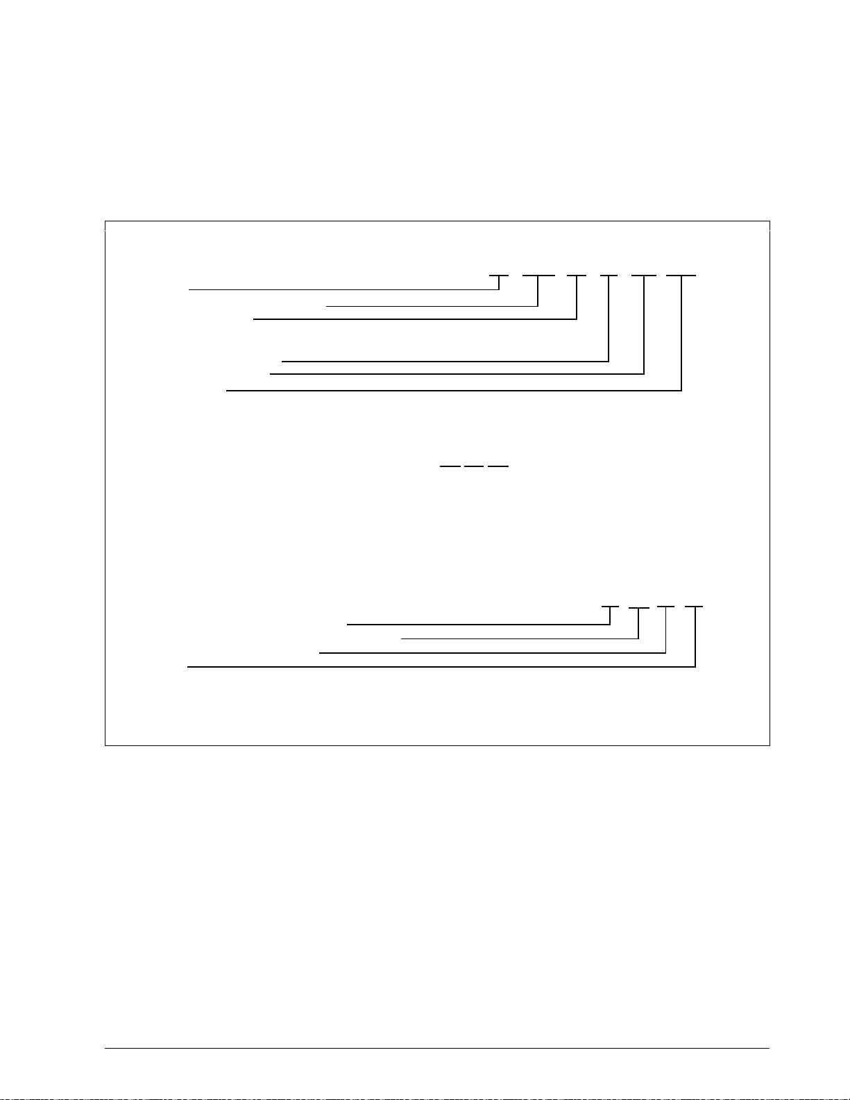
4.5 Write Analog Parameters, Continued
Example
Figure 4-3 is an example of a Write of an analog parameters message
exchange; specifically to change the gain value from 5 to 10; analog I.D.
Code 001.
Figure 4-3 Write Analog Parameter Message Exchange Example
request
Address
Protocol Format (without checksum)
UDC State and Mode
6 = slave, no change
5 = configuration, write
Data Type Code for Analog
Identifying Code for Gain
Gain Value of 10
busy response
ready request
03,0204,66,11, 0 CR LF
03 , 0204 , 65 , 18 , 010.0 , CR LF
8200
00
001 ,
is ready response
Request message received successfully
UDC functioning properly and performed operation
Control state, Automatic LSP Mode
No Alarm
(OPTIONAL) Do a READ operation for Code 001 to verify change to 10.
CR LF00 80 4 0
23095
5/99 RS422/485 ASCII Communications Option Product Manual 51
Page 66

4.6 Write Digital Parameters
Introduction
Request format
The digital identifying codes are Codes 128 through 225. The Write
request and response formats are shown in Tables 4-10, 4-11, 4-12, and 4-
13.
Table 4-10 lists the Write request format, with or without checksum, for
digital I.D. Codes 128 through 255.
Where:
AA = Station Address (Each loop of a 2 loop controller has a
unique address – see "Message Exchange")
X = UDC State and Mode (Hex – see "Message Exchange")
MMM = Identifying Code for Digital Parameter (128 to 255)
DDD = Digital Value (always three characters)
CS = Checksum Value (two digit hex – see "Checksum")
CR = Carriage Return
LF = Line Feed
Table 4-10 Write Request Format for Digital I.D. Codes
Format Type Format
With Checksum AA, 4204, X5, 11*, MMM, DDD, CS CR LF
“Busy” response
Without Checksum AA, 0204, X5, 11*, MMM, DDD, CR LF
*Use 41 for extended digital I.D. codes 128 through 159, UDC 3300, UDC 6000, or U DC
6300 only.
If the controller did not process the information, the controller will return
a four digit status code, indicating an error in the third and fourth digit.
See “Status Codes.”
Table 4-11 lists the busy responses that can be received with or without
checksum, after a write request that indicates a good write:
Where:
M = Mode (Hex - see “Message Exchange”)
A = Alarm Data (Hex – see "Message Exchange")
CS = Checksum Value (2 digit hex – see "Checksum")
CR = Carriage Return
LF = Line Feed
52 RS422/485 ASCII Communications Option Product Manual 5/99
Page 67

4.6 Write Digital Parameters, Continued
“Busy” response,
continued
Table 4-11 Busy Response
Format Type Format
With Checksum OOO2MA, CS, CR LF
Without Checksum OOO2MA, CR LF
“Ready” request
“Is Ready” response
After receiving a “Busy” response, enter a “Ready” request. Table 4-12
lists the “Ready” request format, with or without checksum.
Table 4-12 Ready Request
Format Type Format
With Checksum 03, 4204, 66, 11, 0 CS CR LF
Without Checksum 03, 0204, 66, 11, 0 CR LF
This is the response to the Ready request. Table 4-13 lists the “Is Ready”
response formats, with or without checksum.
Where:
SS = UDC Status
M = Mode (Hex - see “Message Exchange”)
A = Alarm Data (Hex – see "Message Exchange")
CS = Checksum Value (two digit hex – see "Checksum")
CR = Carriage Return
LF = Line Feed
Table 4-13 “Is Ready” Response
Format Type Format
With Checksum 00SSMA, CS, CR LF
Without Checksum 00SSMA, CR LF
Check write
transaction
5/99 RS422/485 ASCII Communications Option Product Manual 53
To check the value of a change, do a “Read” for the particular (I.D. Code)
you have changed.
Page 68

4.6 Write Digital Parameters, Continued
Example
Figure 4-4 is an example of a Write of a digital parameter message
exchange; specifically, to change the setpoint ramp time to 60 minutes
(Code 174).
Figure 4-4 Write Digital Parameter Message Exchange Example
request
Address
Protocol Format (without checksum)
UDC State and Mode
6 = slave, no change
5 = configuration, write
Data Type Code for Digital
Identifying Code for SP Ramp Time
SP Ramp Time in Minutes
busy response
03 , 0204 , 65 , 11 , 060 , CR LF
8200
00
174 ,
ready request
03,0204,66,11,000,0 CR LF
is ready response
Request message received successfully
UDC functioning properly and performed operation
Control state, Automatic LSP Mode
No Alarm
(OPTIONAL) Do a READ operation for Code 174 to verify change.
CR LF00 00 4 0
23096
54 RS422/485 ASCII Communications Option Product Manual 5/99
Page 69

Section 5 – Read, Write and Override Parameters
on UDC 3000 Versa-Pro Controllers
5.1 Overview
Introduction
What’s in this section
This section contains information concerning reading, writing, and
overriding parameters on the UDC 3000 Controllers. There are two types
of parameters:
• Data Transfer—these parameters include reading control data, option
status, and reading or changing setpoints or outputs.
• Configuration Data—all the configuration data is listed in the order in
which it appears in the controller.
Each type of parameter has the identifying codes listed with it. Follow the
message exchange rules listed in “Read and Write Operations.”
This section contains the following topics:
Topic See Page
5.1 Overview 55
5.2 Reading Control Data 57
5.3 Option Status 58
5.4 Miscellaneous Read Only’s 59
5.5 Setpoints 61
5.6 Using a Computer Setpoint 62
5.7 Overriding Input 1 63
5.8 Canceling the Override 64
5.9 Reading or Changing the Output 65
5.10 Local Setpoint/PID Set Selection and Setpoint Ramp
Status
66
5/99 RS422/485 ASCII Communications Option Product Manual 55
Page 70

5.1 Overview - UDC 3000, Continued
What’s in this section,
continued
Topic See Page
General information
5.11 Configuration Parameters
TUNING
SP RAMP/SP PROG
ADAPTIVE TUNE
ALGORITHMS
INPUT 1
INPUT 2
CONTROL
OPTIONS
COMRS422
ALARMS
Analog Parameters
• Whenever analog parameters 001 through 107 (those that can be
changed via Communications) are changed, a write cycle occurs
immediately after receipt of the message.
Override Parameters
• Override analog parameters 123, 124, and 125 (computer setpoint,
output, and input) are not stored in non-volatile memory and can be
changed as frequently as desired with no effect on non-volatile memory
retentivity, but the controller must remain in slave mode.
68
69
71
74
75
76
78
79
81
82
83
Digital Parameters
• Whenever digital configuration parameters 128 through 250 are
updated via communications, the non-volatile memory is updated as
soon as the message is received.
56 RS422/485 ASCII Communications Option Product Manual 5/99
Page 71

5.2 Reading Control Data - UDC 3000
Overview
I.D. codes
You can Read the following control data from the UDC 3000 controller.
• Input 1
• Input 2
• PV
• Internal RV
• PV, Setpoint, Output
Use the identifying codes listed in Table 5-1 to read the specific items.
A Write request for these codes will result in an Error message.
Table 5-1 Control Data Parameters
Parameter
Description
Input #1 118 18 In Engineering Units or
Input #2 119 18 In Engineering Units or
PV 120 18 In Engineering Units or
Identifying
Code
Format
Code
Range or Selection
Percentage
Percentage
Percentage
Internal RV 121 18 In Engineering Units or
Percentage
PV, Setpoint, and
Output*
*This READ request will give a three var iable response (see READ/WRITE operation).
122 18 In Engineering Units or
Percentage
5/99 RS422/485 ASCII Communications Option Product Manual 57
Page 72

5.3 Read Option Status - UDC 3000
Read
Doing a Read of I.D. Code 185 listed in Table 5-2 will tell you which of
the available options are enabled/installed or disabled/not installed.
Table 5-2 Option Status
Parameter
Description
Option Status
(read only)
The data field in the response message will be a decimal number from
0 to 255. Convert the decimal number to binary as shown in Figure 5-1 to
determine which options are or are not active.
Figure 5-1 Option Status Information
0 to 255
Convert decimal to binary
Identifying
Code
Format
Code
Range or Selection
185 11 See Figure 5-1
Input 2
Digital Inputs
Input 2
Adaptive Tune
Set Point
Programming
Not Applicable
Not Applicable
Not Applicable
0 = disabled
1 = enabled
0 = not installed
1 = installed
0 = not installed
1 = installed
0 = not installed
1 = installed
0 = not installed
1 = installed
EXAMPLE:
Binary
023
0
0
Input 2 – enabled
Digital Inputs - installed
Input 2 – installed
Set Pont Programming - Installed
0101
1
1
23097
58 RS422/485 ASCII Communications Option Product Manual 5/99
Page 73

5.4 Miscellaneous Read Only’s - UDC 3000
I.D. codes for read
only’s
The identifying codes listed in Table 5-3 represent some parameters that
are Read only. No Writes allowed.
Table 5-3 Miscellaneous Read Only’s
Parameter
Description
Output Current
Calibration 0%
Output Current
Calibration 100%
Software Type 157 11 READ only
Software Version 167 11 0 to 225
Identifying
Code
33 18 READ only
34 18 READ only
Format
Code
Range or Selection
31 = Basic UDC 3000
32 = Field upgrade for Adaptive
Tune
33 = Field upgrade for Adaptive
Tune + Setpoint
Programming
37 = Limit Controller
UDC Error Status 255 11 See below READ/WRITE*
001 = Emergency Manual
002 = Failsafe
004 = Working Calibration
Checksum Error
008 = Configuration Checksum
Error
016 = Parameter Limit Indicator
032 = Hardware Failure
064 = Restart after Shed
128 = Configuration/Calibration
Memory Changed
*Write to clear.
FOR EXAMPLE: If Read returns 192 (restart after shed-064 plus
configuration change -128)
Write 192 to 255
Read returns 000 (clear)
5/99 RS422/485 ASCII Communications Option Product Manual 59
Page 74

5.4 Miscellaneous Read Only’s - UDC 3000, Continued
Error status
definitions
Table 5-4 lists the UDC error status codes and their definitions.
Table 5-4 Error Status Definitions
Status
Code
001 Emergency Manual Indicates that the output of the unit which
002 Failsafe Error occurs whenever the control
004 Working Calibration
Checksum Error
008 Configuration Checksum
Error
Error Definitions
has been in slave operation, is under
manual control, locally. Error remains
until local control is relinquished at the
controller.
reverts to failsafe operation and remains
as long as the condition exists.
Indicates that an error exists in the
working calibration data. Re-select the
inputs to load factory calibration data or
field calibrate the inputs.
Error exists in the configuration data.
Verify configuration data at the keyboard.
Checksum will be recomputed by
stepping the controller through the status
tests.
016 Parameter Limit Indicator A limit condition exists on one of the
following: PV, RV, Input 1, Input 2, Input
3, Computer Setpoint. User must
determine EXACT limit condition and
correct.
032 Hardware Failure Indicates either a RAM test failure or
Input 1, Input 2, Input 3 failure on two
consecutive conversions.
064 Restart After Shed Error occurs whenever a shed of slave
override is performed. Error is reset
following a WRITE command to I.D.
Code 255 (064).
128 Configuration /Calibration
Memory Changed
Error occurs whenever shed,
configuration, or calibration changed.
Also occurs whenever there is a change
of state in 001, 002, 004, 008, or 016.
Error is reset following a WRITE
command to I.D. Code 255.
60 RS422/485 ASCII Communications Option Product Manual 5/99
Page 75

5.5 Setpoints - UDC 3000
Overview
I.D. codes
You can use two separate setpoints in the UDC 3000 Controller. The
identifying codes listed in Table 5-5 allow you to select which setpoint
you want to use and to enter a value in Engineering Units or Percent
(whichever is selected at Code 161) for that setpoint via communications.
Make your selection using I.D. Code 173 and enter the value for the
setpoint chosen using I.D. Code 39 (SP 1) or 53 (SP 2).
Table 5-5 Setpoint Code Selections
Parameter
Description
Local Setpoint #1 39 18 Value within the setpoint
Local Setpoint #2 53 18 Value within the setpoint
Local Setpoint
Select
Identifying
Code
173 11 000 = Local Set
Format
Code
Range or Selection
range limits
range limits
Point #1 only
001 = 2nd Local Setpoint
via keyboard or
communications*
Associated
parameters
*I.D. Code 131—second input function must be set to 0 (LSP).
Refer to Table 5-6 for the codes required to display or change any of the
parameters associated with setpoints.
Table 5-6 Setpoint Associated Parameters
Parameter Code
Setpoint Limits 007, 008
Computer Setpoint 125
Setpoint Program/Ramp 178
5/99 RS422/485 ASCII Communications Option Product Manual 61
Page 76

5.6 Using a Computer Setpoint (Overriding Controller
Setpoint) -
Overview
I.D. codes
Shed
Override display
UDC 3000
You can use a setpoint generated from the computer to override the
setpoint being used by the controller.
The value generated by the computer will have ratio and bias applied by
the controller.
Use the identifying code in Table 5-7 to enter the computer setpoint.
The computer setpoint override will continue until "SHED" from
communications occurs or the controller is placed into monitor mode
through communications. Doing periodic "SLAVE READS" within the
shed time will allow the override to continue until communication is
stopped and shed time elapses.
ATTENTION
indefinitely or until the Override is canceled. (See Override selection
I.D. Code 183.)
When SP is overridden, the left most digit in the upper display
becomes a "C."
0 Shed (code 154) allows the Override to continue
Associated
parameters
Table 5-7 Computer Setpoint Selection
Parameter
Description
Computer Setpoint 125 18 Within the Setpoint Range
Identifying
Code
Format
Code
Range or Selection
Limits in Engineering Units
or Percent.
Refer to Table 5-8 for the codes required to display or change any of the
parameters associated with the computer setpoint.
Table 5-8 Computer Setpoint Associated Parameters
Parameter Code
Setpoint Limits 007, 008
Local Setpoint #1 039
Local Setpoint #2 053
Local Setpoint Selection 173
62 RS422/485 ASCII Communications Option Product Manual 5/99
Page 77
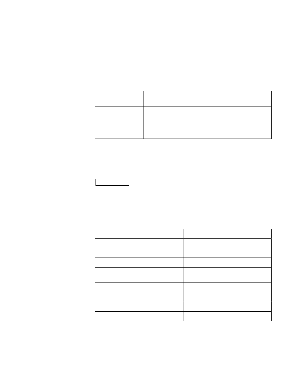
5.7 Overriding Input 1 - UDC 3000
Overview
Override display
Shed
You can override the Input 1 value in the controller using I.D. Code 124
as shown in Table 5-9.
When you override the PV, the first digit in the upper display
becomes a “C.”
Table 5-9 Input 1 Override Code
Parameter
Description
Override Input 1 124 18 Within the input 1 limits in
Identifying
Code
Format
Code
Range or Selection
Engineering Units or
Percent (whichever is
selected at I.D. Code
161).
The Override to Input 1 will continue until “SHED” from communications
occurs or the controller is placed into monitor via communications. Doing
Reads within the shed time will allow the override to continue until Reads
are stopped and shed time elapses (I.D. Code 154).
ATTENTION
0 Shed allows override to continue indefinitely or until
override is canceled. (See Override Selection, I.D. Code 183.)
Associated
parameters
Refer to Table 5-10 for the codes required to display or change any of the
parameters associated with Input 1.
Table 5-10 Input Override Associated Parameters
Parameter Code
High/Low Range Values (Read Only) 029,030
Temperature Units (Read Only) 129
Input 1 Type (Read Only) 168
Transmitter Characterization
(Read Only)
Input 1 Bias 107
Input 1 Filter Time Contrast 042
Burnout 164
Emissivity 023
169
5/99 RS422/485 ASCII Communications Option Product Manual 63
Page 78

5.8 Canceling the Override - UDC 3000
Overview
I.D. codes
Doing a Read of I.D. Code 183 will tell you which Override is active—
Input 1 (PV) or Setpoint.
Doing a Write lets you cancel either the Input 1 override set at Code 124
or setpoint override set at Code 125 or both.
Using the identifying code in Table 5-11 to Read or Write your selection.
Table 5-11 PV or Setpoint Override Cancellation
Parameter
Description
Override Selection 183 11 001 = Cancels Input 1
Identifying
Code
Format
Code
Range or Selection
(PV) Override
008 = Cancels Setpoint
Override
009 = Cancels Both
Overrides
The example below cancels both Input 1 and setpoint overrides:
XX,0204,65,11,183,009,0 CR LF
64 RS422/485 ASCII Communications Option Product Manual 5/99
Page 79

5.9 Reading or Changing the Output - UDC 3000
Overview
I.D. codes
Associated
parameters
You can read the output of a particular UDC 3000 controller (Read
Transaction) or you can change it to suit your needs. (Do a Write
Transaction.)
Use the identifying code in Table 5-12 to monitor (Read) or change
(Write) the output (in manual only).
ATTENTION
To Write (change) the output, the controller must first be in
manual mode.
Table 5-12 Reading or Changing the Output
Parameter
Description
Output 123 18 -5 to +105% of full span
Identifying
Code
Format
Code
Range or Selection
(current output)
0 to 100%
(relay type output)
Refer to Table 5-13 for the codes required to display or change any of the
parameters associated with the output.
Table 5-13 Associated Output Codes
Parameter Code
Output Direction 135
Output Limits 14, 15
Output Dropoff Limits 20
Failsafe Output Values 40
Output Hysteresis 19
Output Type (Read only) 160
5/99 RS422/485 ASCII Communications Option Product Manual 65
Page 80

5.10 Local Setpoint/PID Set Selection/Setpoint Ramp Status
- UDC 3000
Overview
Read
Write
Identifying Code 250 lets you monitor or make selections for:
• Tuning Parameter Set #1 or #2
If Tuning Sets selection is “two keyboard” code 171 = 001
• Local Setpoint #1 or #2
If ”2 Local Setpoints” is selected 131 = 0, 173 = 1
• Run or Hold Setpoint Ramp or a Setpoint Program Data
If SP Ramp or SP Program is enabled 178 = 1 Program, 178 = 2 Ramp
Table 5-14 is a table of numbers that could be returned by the UDC 3000
controller. When a Read is requested for this I.D. Code (250) you can
determine which parameters are active from this table.
To Write information to the controller, select what parameters you want
from Table 5-14 and enter the associated number in the data field of the
Write request.
For example:
• Maintain TUNING SET #2
• Maintain LOCAL SET POINT #1
• CHANGE A SET POINT PROGRAM TO RUN
READ 250 response is 020 or 022
WRITE 250 (023), Response Busy
READ 250 Response is 023
Note: some of the numbers are Read only.
Table 5-14 LSP/PID Set Selection and Setpoint Ramp Status
Parameter
Description
Enhanced Function 250 11 See Figure 5-2
Identifying
Code
Format
Code
Range or Selection
66 RS422/485 ASCII Communications Option Product Manual 5/99
Page 81

5.10 Local Setpoint/PID Set Selection /Setpoint Ramp
Status
- UDC 3000, Continued
Write, continued
Figure 5-2 I.D. Code 250 Indications
Tuning Set #2 Selection
Local Set Point #2 Selection
Tuning Set #2 Selection
Local Set Point #1 Selection
Tuning Set #1 Selection
Local Set Point #2 Selection
Tuning Set #1 Selection
Local Set Point #1 Selection
Set Point Ramp or Program Data Selections
None or SP Ramp, Enabled Not in Progress, (READ) 000 008 016 024
SP Ramp in Progress, Hold (READ/WRITE) 002 010 018 026
SP Ramp in Progress, Run (READ/WRITE) 003 011 019 027
SP Program, Enabled Not in Progress, (READ)
SP Program in Progress, Hold (READ/WRITE)
SP Program in Progress, Run (READ/WRITE)
004 012 020 028
006 014 022 030
007 015 023 031
23098
5/99 RS422/485 ASCII Communications Option Product Manual 67
Page 82

5.11 Configuration Parameters - UDC 3000
Overview
Listed on the following pages are the identifying codes for the parameters
in the various setup groups in the UDC 3000 controller. The table below
lists the setup groups and the table number in which they are listed. Most
of the parameters are configurable through the Host. Some are READ
ONLY and are indicated as such and cannot be changed.
Setup Group Table Number
TUNING 5-15
SP RAMP/PROG 5-16
ADAPTIVE 5-17
ALGORITHMS 5-18
INPUT 1 5-19
INPUT 2 5-20
CONTROL 5-21
OPTIONS 5-22
COMMUNICATIONS 5-23
ALARMS 5-24
Reading or Writing
Do a Read or Write (see “Read/Write Operations”) depending on your
requirements using the identifying code and format code listed in the
tables. The range or selection available for each range is listed in the
tables.
68 RS422/485 ASCII Communications Option Product Manual 5/99
Page 83

5.11 Configuration Parameters - UDC 3000, Continued
Tuning
Table 5-15 lists all the I.D. Codes and ranges or selection for the function
parameters in the setup group “TUNING.”
Table 5-15 Setup Group-Tuning
Parameter
Description
Heat Gain or PB 001 18 PB=0.1 to 9999%
Heat Rate 002 18 0.08 to 10.00 Minutes
Heat Reset or RPM 003 18 Reset=0.00 to 50.0 min/rpt
Manual Reset 013 18 -100 to +100% Output
Cool Gain/Gain #2
or PB
Cool Rate/Rate #2 005 18 0.08 to 10.00 Minutes
Cool Rate/Reset #2
or RPM
Heat Cycle Time 158 11 1 to 120 Seconds
Identifying
Code
004 18 PB=0.1 to 9999%
006 18 Reset=0.00 to 50.0 min/rpt
Format
Code
Range or Selection
Gain=0.1 to 9999
RPM = 0.00 to 50.0 rpt/min
Gain=0.1 to 9999
RPM = 0.00 to 50.0 rpt/min
Cool Cycle Time 159 11 1 to 120 Seconds
Lockout
Changes to data
always possible via
communication
regardless of this
configuration.
132 11 0 = None
1 = Calibration
2 = +Configuration
3 = +View
4 = Maximum
(N/A for Limit)
5/99 RS422/485 ASCII Communications Option Product Manual 69
Page 84

5.11 Configuration Parameters - UDC 3000, Continued
Tuning, continued
Table 5-15 Setup Group-Tuning, Continued
Parameter
Description
Keyboard Lockout 191 11 0 = All keys enabled
Identifying
Code
Format
Code
Range or Selection
1 = Manual Auto Key
Locked
2 = Setpoint Select Key
Locked
3 = Manual/Auto and
Setpoint Select Keys
Locked
4 = Run Hold Key Locked
5 = Run Hold Key and
Manual/Auto Keys
Locked
6 = Run Hold Key and
Setpoint Select Keys
Locked
7 = Run Hold, Setpoint
Select, and
Manual/Auto Keys
Locked.
70 RS422/485 ASCII Communications Option Product Manual 5/99
Page 85

5.11 Configuration Parameters - UDC 3000, Continued
Setpoint
Ramp/Rate/Program
Table 5-16 lists all the I.D. Codes and ranges or selections for the function
parameters in the setup group “SP RAMP/RATE/PROGRAM.”
Table 5-16 Setup Group-SP Ramp, Rate, or SP Program
Parameter
Description
Setpoint Program
Ramp Selection
SP Ramp
Single SP Ramp
Time
Final Ramp SP
Value
SP Rate
Rate Up 108 18 0 to 9999
Identifying
Code
178 11 0 = SP Program, Rate,
174 11 0 to 255 (Minutes)
026 18 PV Range in Engineering
Format
Code
Range or Selection
and Ramp Disabled
1 = SP Program Enabled
2 = SP Ramp Enabled
3 = SP Rate Enabled
Units
Rate Down 109 18 0 to 9999
SP Program
Start Segment
Number
End Segment
Number (Soak)
Program Recycles 177 11 0 to 99
Guaranteed Soak
Deviation
Segment #1 Ramp
Time
Segment #2 Soak
Setpoint Value
Segment #2 Soak
Time
Segment #3 Ramp
Time
175 11 1 to 11
176 11 2, 4, 6, 8, 10, or 12
087 18 0 to 99.9 (0 = no soak)
057 18 99.59 (0-99 Hrs :
0-59 Min) or 999 (0-999
Deg/Min)
058 18 Within Setpoint Limits
059 18 99.59 (0-99 Hrs :
0-59 Min)
060 18 99.59 (0-99 Hrs :
0-59 Min) or 999 (0-999
Deg/Min)
5/99 RS422/485 ASCII Communications Option Product Manual 71
Page 86

5.11 Configuration Parameters - UDC 3000, Continued
Setpoint
Ramp/Rate/Program,
continued
Table 5-16 Setup Group-SP Ramp, Rate, or SP Program, Continued
Parameter
Description
Segment #4 Soak
Setpoint Value
Segment #4 Soak
Time
Segment #5 Ramp
Time
Segment #6 Soak
Setpoint Value
Segment #6 Soak
Time
Segment #7 Ramp
Time
Segment #8 Soak
Setpoint Value
Segment #8 Soak
Time
Identifying
Code
061 18 Within Setpoint Limits
062 18 99.59 (0-99 Hrs :
063 18 99.59 (0-99 Hrs :
064 18 Within Setpoint Limits
065 18 99.59 (0-99 Hrs :
066 18 99.59 (0-99 Hrs :
067 18 Within Setpoint Limits
068 18 99.59 (0-99 Hrs :
Format
Code
Range or Selection
0-59 Min)
0-59 Min) or 999 (0-999
Deg/Min)
0-59 Min)
0-59 Min) or 999 (0-999
Deg/Min)
0-59 Min)
Segment #9 Ramp
Time
Segment #10 Soak
Setpoint Value
Segment #10 Soak
Time
Segment #11 Ramp
Time
Segment #12 Soak
Setpoint Value
Segment #12 Soak
Time
Program End State 181 11 0 = Disable SP Program
Controller Status at
Program End
069 18 99.59 (0-99 Hrs :
0-59 Min) or 999 (0-999
Deg/Min)
070 18 Within Setpoint Limits
071 18 99.59 (0-99 Hrs :
0-59 Min)
072 18 99.59 (0-99 Hrs :
0-59 Min) or 999 (0-999
Deg/Min)
073 18 Within Setpoint Limits
074 18 99.59 (0-99 Hrs :
0-59 Min)
1 = Hold at Program End
180 11 0 = Last Setpoint
1 = Manual, Failsafe
72 RS422/485 ASCII Communications Option Product Manual 5/99
Page 87

5.11 Configuration Parameters - UDC 3000, Continued
Setpoint
Ramp/Rate/Program,
continued
Table 5-16 Setup Group-SP Ramp, Rate, or SP Program, Continued
Parameter
Description
Engineering Units or
Ramp Segments
Present Segment
Number
Time Remaining —
Minutes
Time Remaining —
Hours
Cycles Remaining 254 11 (READ ONLY)
Identifying
Code
182 11 0 = HRS:MIN
251 11 (READ ONLY)
252 11 (READ ONLY)
253 11 (READ ONLY)
Format
Code
Range or Selection
1 = Degrees/Minute
Recycles—Elapsed
Cycles
5/99 RS422/485 ASCII Communications Option Product Manual 73
Page 88

5.11 Configuration Parameters - UDC 3000, Continued
Adaptive tune
Table 5-17 lists all the I.D. Codes and ranges or selections for the function
parameters in the setup group “ADAPTIVE TUNE.”
Table 5-17 Setup Group-Adaptive Tune
Parameter
Description
Adaptive Tune
Selection
Setpoint Change 153 11 Read Only
Process Gain (KPG) 114 18 0.01 to 50.0
Adaptive Tune Error
Codes
Identifying
Code
152 11 Read only
151 11 Read Only
Format
Code
Range or Selection
0 = Disabled
3 = SP Tune
4 = Fast SP Tune
5 to 15
0 = None
1 + Output > or < Output
Limits or Manual
Step = 0
2 = Output > or < Heat/
Cool Limits
4 PV Changes Insufficient
5 = Process Identification
failed
6 = Calculated Reset
Outside Reset Limits
7 = Calculated Gain
Outside Gain Limits
8 = Adaptive Tune
Aborted on Command
9 = Input #1 Error
Detected
10 = Adaptive Tune Illegal
during Ramp/SP
Program
11 = Adaptive Tune
Aborted when
External Switch
Detected
12 = Adaptive Tune
Running
74 RS422/485 ASCII Communications Option Product Manual 5/99
Page 89

5.11 Configuration Parameters - UDC 3000, Continued
Algorithm
Table 5-18 lists all the I.D. codes and ranges or selections for the function
parameters in the setup group “ALGORITHM.”
Table 5-18 Setup Group-Algorithm
Parameter
Description
Algorithm Selection 128 11 0 = ON/OFF
Output Type 160 11 READ ONLY
Identifying
Code
Format
Code
Range or Selection
1 - PID-A
2 = PID-B
3 = PD-A with Manual
Reset
4 = Three Position Step
0 = Not Allowed
1 = Position Proportional
2 = Relay Simplex
3 = Relay Duplex
4 = Current
5 = Current Duplex - Full
Range*
6 = Relay/Current Duplex
(relay on heat)
7 = Relay/Current duplex
(relay on cool)
*Current Duplex with split
range not available with
communications installed.
5/99 RS422/485 ASCII Communications Option Product Manual 75
Page 90

5.11 Configuration Parameters - UDC 3000, Continued
Input 1
Table 5-19 lists all the I.D. Codes and ranges or selections for the function
parameters in the setup group “INPUT 1.”
Table 5-19 Setup Group-Input 1
Parameter
Description
Decimal Point
Location
Temperature Units 129 11 0 = °F
Input Type 1 168 11 READ ONLY
Identifying
Code
155 11 0 = XXXX Fixed
Format
Code
Range or Selection
1 = XXX.X Floating DP
with none
2 = XX.XX Fixed
1 = °C
2 = No Units
0 =B T/C
1 = E T/C H
2 = E T/C L
3 = J T/C H
4 = J T/C L
5 = K T/C H
6 = K T/C L
7 = N T/C H
8 = N T/C L
9 = R T/C
10 = S T/C
11 = T T/C H
12 = T T/C L
13 = W T/C H
14 = W T/C L
15 = 100 PLAT.
16 = 500 PLAT
17 = 100-LO
18 = 4-20 mA*
19 = 0-10 mV*
20 = 10-50 mA*
21 = 1-5 Volts*
22 = 0-10 Volts*
23 = NIC T/C
24 = Radiamatic (RH)
* Limit Control: Non FM Only
76 RS422/485 ASCII Communications Option Product Manual 5/99
Page 91

5.11 Configuration Parameters - UDC 3000, Continued
Input 1, continued
Table 5-19 Setup Group-Input 1, Continued
Parameter
Description
Transmitter
Characterization
Identifying
Code
169 11
Format
Code
Range or Selection
READ ONLY
0 =B T/C
1 = E T/C H
2 = E T/C L
3 = J T/C H
4 = J T/C L
5 = K T/C H
6 = K T/C L
7 = N T/C H
8 = N T/C L
9 = R T/C
10 = S T/C
11 = T T/C H
12 = T T/C L
13 = W T/C H
14 = W T/C L
15 = 100 PLAT.
16 = 500 PLAT
17 = 100-LO
18 = LINEAR
19 = SQ ROOT
20 = NIC T/C
21 = Radiamatic (RH)
High Range Value 029 18 READ ONLY - For
TC/RTD Types ( In
Engineering Units, T/CRTD)
Low Range Value 030 18 READ ONLY-For TC/RTD
Types (In Engineering
Units, T/C-RTD)
Bias 107 18 -999.9 to 9999
Filter Time Constant 042 18 0 to 120 Seconds
(No Filter = 0 )
Burnout (Open
Circuit Detection)
164 11 0 = None and Failsafe
1 = Upscale
2 = Downscale
Limit:
0=Downscale
1=Upscale
Writes Illegal
Power Line
Frequency
166 11 0 = 60 Hz
1 = 50 Hz
Emissivity 023 18 0.01 to 1.00
5/99 RS422/485 ASCII Communications Option Product Manual 77
Page 92

5.11 Configuration Parameters - UDC 3000, Continued
Input 2
Table 5-20 lists all the I.D. Codes and ranges or selections for the function
parameters in the setup group “INPUT 2.”
Table 5-20 Setup Group-Input 2
Parameter
Description
Input Type 170 11 READ ONLY
Transmitter
Characterization
Identifying
Code
171 11 READ ONLY
Format
Code
Range or Selection
(18 = LINEAR)
0 = B T/C
1 = E T/C H
2 = E T/C L
3 = J T/C H
4 = J T/C L
5 = K T/C H
6 = K T/C L
7 = N T/C H
8 = N T/C L
9 = R T/C
10 = S T/C
11 = T T/C H
12 = T T/C L
13 = W T/C H
14 = W T/C L
15 = 100 PLAT.
16 = 500 PLAT
17 = 100-LO
18 = LINEAR
19 = SQ ROOT
20 = NIC T/C
21 = Radiamatic (RH)
High Range Value 035 18 READ ONLY
(In Engineering Units)
Low Range Value 036 18 READ ONLY
(In Engineering Units)
Filter Time Constant 043 18 0 to 120 Seconds
(No Filter = 0)
78 RS422/485 ASCII Communications Option Product Manual 5/99
Page 93

5.11 Configuration Parameters - UDC 3000, Continued
Control
Table 5-21 lists all the I.D. Codes and ranges or selections for the function
parameters in the setup group “CONTROL.”
Table 5-21 Setup Group-Control
Parameter
Description
Number of Tuning
Sets
PV Switchover
Value
Remote Setpoint
Source
Local Setpoint
Select
Identifying
Code
172 11 0 = One Set Only
056 18 Within the PV Range
131 11 0 = None
173 11 000 = Local Setpoint #1
Format
Code
Range or Selection
1 = Two Sets (keyboard or
communications
2 = Two Sets (Auto Switch
PV)
3 = Two Sets (Auto Switch
PV)
1 = Input 2
Only
001 = 2nd Local Setpoint
via keyboard or
communications*
Ratio 021 18 -20.00 to +20.00
Bias 022 18 -999 to +9999 in
Engineering Units
LSP Tracking 138 11 0 = None
1 = Rsp
2 = PV
Power Up Recall 130 11 0 = Manual—LSP
1 = Automatic—LSP
2 = Automatic—RSP
3 = Last Mode, Last
Setpoint
4 = Last Mode, Last Local
Setpoint
High Setpoint Limit 007 18 Within the PV Range
(Engineering Units)
Low Setpoint Limit 008 18 Within the PV Range
(Engineering Units)
5/99 RS422/485 ASCII Communications Option Product Manual 79
Page 94

5.11 Configuration Parameters - UDC 3000, Continued
Control, continued
Table 5-21 Setup Group-Control, Continued
Parameter
Description
Control Output
Direction
Output Change
Rate Limiting
Output Change
Rate Up
Output Change
Rate Down
High Output Limit 014 18 -5 to +105% of output
Low Output Limit 015 18 -5 to +105% of output
Output Dropoff
Limit
Deadband 018 18 -5 to +25.0%
Identifying
Code
135 11 0 = Direct
189 11 0 = Disable
110 18 1 to 9999 %/MIN
111 18 1 to 9999 %/MIN
020 18 -5 to +105% of output
Format
Code
Range or Selection
1 = Direct
2 = Reverse
3 = Reverse
1 = Enable
Output Hysteresis 019 18 0 to 5.0% of PV span
Failsafe Output
Value
Proportional Band
Units
Reset Units 149 11 0 = Minutes
*I.D. Code 131—Second Input Function must be set to 0 (LSP).
040 18 Within the Range of Output
Limits
148 11 0 = Gain
1 = Proportional Band
1 = Repeats per Minute
80 RS422/485 ASCII Communications Option Product Manual 5/99
Page 95

5.11 Configuration Parameters - UDC 3000, Continued
Options
Table 5-22 lists all the I.D. Codes and ranges or selections for the function
parameters in the setup group “OPTIONS.”
Table 5-22 Setup Group-Options
Parameter
Description
Digital Input #1 186 11
Identifying
Code
Format
Code
Range or Selection
0 = None
1 = To Manual
2 = To Local Setpoint #1
3 = To Local Setpoint #2
4 = To Direct Action
5 = To Hold
6 = To PID 2
7 = PV = Input 2
8 = To Run
9 = Reset SP Program
10 = Inhibit PID Integral (I)
Action
11 = To Manual Failsafe
12 = Disable Keyboard
13 = To Automatic
14 = To Timer
15 = To Auto/Manual Station
For Digital Input combinations,
see Figure 5-3
Digital Input #2 187 11 Same as Digital Input #1
(Code 186)
Digital Input Status 188 11 0 = Digital Input 1 Open
Digital Input 2 Open
1 = Digital Input 1 Closed
Digital Input 2 Open
2 = Digital Input 1 Open
Digital Input 2 Closed
3 = Digital Input 1 Closed
Digital Input 2 Closed
5/99 RS422/485 ASCII Communications Option Product Manual 81
Page 96

5.11 Configuration Parameters - UDC 3000, Continued
COMRS422
Table 5-23 lists all the I.D. Codes and ranges or selections for the function
parameters in the setup group “COMRS422.”
Table 5-23 Setup Group-COMRS422
Parameter
Description
Shed Time 154 11 0 to 255 Sample Periods
Shed Controller
Mode and Output
Level
Shed Setpoint
Recall
Identifying
Code
162 11 0 = Last Mode and Last
163 11 0 = Use UDC Setpoint as
Format
Code
Range or Selection
0 = No Shed
Output
1 = Manual Mode, Last
Output
2 = Manual Mode, Failsafe
Output
3 = Automatic Mode
determined by
Remote/Local mode,
LSP unchanged
Communication
Units
1 = Use UDC Setpoint as
determined by
Remote/Local mode,
LPS = Last setpoint prior
to shed
161 11 0 = Percent (%)
1 = Engineering Units
82 RS422/485 ASCII Communications Option Product Manual 5/99
Page 97

5.11 Configuration Parameters - UDC 3000, Continued
Alarms
Table 5-24 lists all the I.D. Codes and ranges or selections for the function
parameter in the setup group “ALARMS.”
Table 5-24 Setup Group-Alarms
Parameter
Description
Alarm #1 SP #1
Value
Alarm #1 SP #2
Value
Alarm #2 SP #1
Value
Alarm #2 SP #2
Value
Alarm #1 SP #1
Type
Identifying
Code
009 18 Value in Engineering Units
010 18 Value in Engineering Units
011 18 Value in Engineering Units
012 18 Value in Engineering Units
140 11 0 = None
Format
Code
Range or Selection
1 = Input 1
2 = Input 2
3 = PV
4 = Deviation
5 = Output
6 = Alarm on Shed
7 = SP Event ON
8 = SP Event OFF
9 = Alarm on Manual
Alarm #1 SP #2
Type
Alarm #2 SP #1
Type
Alarm #2 SP #2
Type
Alarm #1 SP #1
State
Alarm #1 SP #2
State
Alarm #2 SP #1
State
Alarm #2 SP #2
State
Alarm Hysteresis 041 18 0 to 100.0% of full span or
142 11 Same as Code 140
144 11 Same as Code 140
146 11 Same as Code 140
141 11 0 = Low Alarm
1 = High Alarm
143 11 0 = Low Alarm
1 = High Alarm
145 11 0 = Low Alarm
1 = High Alarm
147 11 0 = Low Alarm
1 = High Alarm
full output
5/99 RS422/485 ASCII Communications Option Product Manual 83
Page 98

5.11 Configuration Parameters - UDC 3000, Continued
Digital input
combinations
Figure 5-3 Digital Input Combinations
For digital input combinations and addresses convert
decimal to binary for read, binary to decimal for write.
18 to 255
Convert decimal to binary
or binary to decimal
128 64 32 16 8 4 2 1
Selection 1 to 15
Input combinations
001 = + to PID2
010 = + to Direct
011 = + to SP2
100 = + disable adaptive
EXAMPLE:
0 1 1 0 1 1 0 0 = 108
Selection 12-Disable Keyboard + to SP2
23108
84 RS422/485 ASCII Communications Option Product Manual 5/99
Page 99

Section 6 – Read, Write and Override Parameters
on UDC 5000 Ultra-Pro Controllers
6.1 Overview
Introduction
This section contains information concerning reading, writing, and
overriding parameters on the UDC 5000 Ultra-Pro Controller. There are
two types of parameters:
• Data Transfer—these parameters include reading control data, option
status, and reading or changing setpoints or outputs.
• Configuration Data—all the configuration data is list in the order in
which it appears in the controller.
Each type of parameter has the identifying codes listed with it. Follow the
message exchange rules listed in “Read and Write Operations.”
5/99 RS422/485 ASCII Communications Options Product Manual 85
Page 100

6.1 Overview - UDC 5000, Continued
What’s in this section
This section contains the following topics:
See Page
6.1 Overview 85
6.2 Reading Control Data 88
6.3 Option Status 89
6.4 Miscellaneous Read Only’s 90
6.5 Setpoints 92
6.6 Using a Computer Setpoint 93
6.7 Overriding the Inputs 95
6.8 PV, Setpoint, or Input Override Status or Cancellation 97
6.9 Reading or Changing the Output 98
6.10 Local Setpoint/PID Set Selection and Setpoint Ramp
Status
6.11 Configuration Parameters Setup Groups
Tuning
Tuning 2
SP Ramp Program
Autotune/Adaptive Tune
Algorithm
Output Algorithm
Input 1
Input 2
Input 3
Control
Control 2
Options
Communications
Alarms
Displays
99
101
102
103
104
107
109
113
114
116
119
121
121
123
124
125
127
86 RS422/485 ASCII Communications Options Product Manual 5/99
 Loading...