

Page 1

UDC3500
Universal Digital Controller
Product Manual
51-52-25-120
September 2006
Industrial Measurement and Control
Page 2

WARRANTY/REMEDY
Honeywell warrants goods of its manufacture as being free of defective materials and faulty
workmanship. Contact your local sales office for warranty information. If warranted goods are
returned to Honeywell during the period of coverage, Honeywell will repair or replace without charge
those items it finds defective. The foregoing is Buyer's sole remedy and is in lieu of all other
warranties, expressed or implied, including those of merchantability and fitness for a
particular purpose. Specifications may change without notice. The information we supply is
believed to be accurate and reliable as of this printing. However, we assume no responsibility for its
use.
While we provide application assistance personally, through our literature and the Honeywell web
site, it is up to the customer to determine the suitability of the product in the application.
Notices and Trademarks
Copyright 2006 by Honeywell
Revision 2
September 2006
Industrial Measurement and Control
Honeywell
1100 Virginia Drive
Fort Washington, PA 19034
UDC3500 is a U.S. registered trademark of Honeywell
Other brand or product names are trademarks of their respective owners.
9/06 UDC3500 Universal Digital Controller Product Manual ii
Page 3

About This Document
Abstract
This document provides descriptions and procedures for the Installation, Configuration, Operation, and Troubleshooting of
your UDC3500 Controller.
Contacts
World Wide Web
The following lists Honeywell’s World Wide Web sites that will be of interest to our customers.
Honeywell Organization WWW Address (URL)
Corporate http://www.honeywell.com
Industrial Measurement and Control http://www.honeywell.com/imc
Telephone
Contact us by telephone at the numbers listed below.
United States and Canada Honeywell 1-800-423-9883 Tech. Support
Organization Phone Number
1-800-525-7439 Service
Web
http://content.honeywell.com/ipc/faq/
9/06 UDC3500 Universal Digital Controller Product Manual iii
Page 4
Symbol Definitions
The following table lists those symbols used in this document to denote certain conditions.
Symbol Definition
This CAUTION symbol on the equipment refers the user to the Product Manual for
additional information. This symbol appears next to required information in the manual.
WARNING
PERSONAL INJURY: Risk of electrical shock. This symbol warns the user of a
potential shock hazard where HAZARDOUS LIVE voltages greater than 30 Vrms, 42.4
Vpeak, or 60 VDC may be accessible. Failure to comply with these instructions
could result in death or serious injury.
ATTENTION, Electrostatic Discharge (ESD) hazards. Observe precautions for
handling electrostatic sensitive devices
Protective Earth (PE) terminal. Provided for connection of the protective earth (green
or green/yellow) supply system conductor.
Functional earth terminal. Used for non-safety purposes such as noise immunity
improvement. NOTE: This connection shall be bonded to protective earth at the source
of supply in accordance with national local electrical code requirements.
Earth Ground. Functional earth connection. NOTE: This connection shall be bonded to
Protective earth at the source of supply in accordance with national and local electrical
code requirements.
Chassis Ground. Identifies a connection to the chassis or frame of the equipment shall
be bonded to Protective Earth at the source of supply in accordance with national and
local electrical code requirements.
9/06 UDC3500 Universal Digital Controller Product Manual iv
Page 5

Contents
1 INTRODUCTION ...................................................................................................1
1.1 Overview.........................................................................................................................................1
1.2 Operator Interface...........................................................................................................................6
1.2.1 Function of Displays and Keys............................................................................................7
1.3 Process Instrument Explorer Software............................................................................................8
1.4 CE Conformity (Europe)...............................................................................................................10
2 INSTALLATION...................................................................................................11
2.1 Overview.......................................................................................................................................11
2.2 Condensed Specifications.............................................................................................................13
2.3 Model Number Interpretation ....................................................................................................... 17
2.4 Control and Alarm Relay Contact Information.............................................................................19
2.5 Mounting.......................................................................................................................................20
2.6 Wiring...........................................................................................................................................22
2.6.1 Electrical Considerations ...................................................................................................22
2.7 Wiring Diagrams...........................................................................................................................24
3 CONFIGURATION...............................................................................................43
3.1 Overview.......................................................................................................................................43
3.2 Configuration Prompt Hierarchy ..................................................................................................45
3.3 Configuration Procedure...............................................................................................................48
3.4 Loop 1 Tuning Set Up Group .......................................................................................................49
3.5 Loop 2 Tuning Set Up Group .......................................................................................................53
3.6 SP Ramp Set Up Group ................................................................................................................56
3.7 Accutune Set Up Group................................................................................................................62
3.8 Algorithm Set Up Group...............................................................................................................67
3.9 Math Set Up Group.......................................................................................................................82
3.10 Logic Gates Set Up Group ........................................................................................................89
3.11 Output Set Up Group.................................................................................................................96
3.12 Input 1 Set Up Group ..............................................................................................................107
3.13 Input 2 Set Up Group ..............................................................................................................111
3.14 Input 3 Set Up Group ..............................................................................................................114
3.15 Input 4 Set Up Group ..............................................................................................................117
3.16 Input 5 Set Up Group ..............................................................................................................120
3.17 Control Set Up Group .............................................................................................................123
3.18 Control 2 Set Up Group ..........................................................................................................132
v UDC3500 Universal Digital Controller Product Manual 9/06
Page 6

3.19 Options Set Up Group.............................................................................................................139
3.20 Communications Set Up Group...............................................................................................150
3.21 Alarms Set Up Group..............................................................................................................154
3.22 Real Time Clock Set Up Group...............................................................................................162
3.23 Maintenance Set Up Group.....................................................................................................163
3.24 Display Set Up Group .............................................................................................................166
3.25 Read Maintenance Set Up Group............................................................................................168
3.26 Time Events Set Up Group .....................................................................................................169
3.27 P.I.E. Tool Ethernet and Email Configuration Screens...........................................................171
3.28 Configuration Record Sheet....................................................................................................174
4 MONITORING AND OPERATING THE CONTROLLER...................................181
4.1 Overview.....................................................................................................................................181
4.2 Operator Interface.......................................................................................................................182
4.3 Entering a Security Code ............................................................................................................182
4.4 Lockout Feature..........................................................................................................................183
4.5 Monitoring Your Controller........................................................................................................185
4.5.1 Annunciators....................................................................................................................185
4.5.2 Viewing the operating parameters....................................................................................186
4.5.3 Diagnostic Messages........................................................................................................187
4.6 Start Up Procedure for Operation ...............................................................................................188
4.7 Control Modes ............................................................................................................................189
4.7.1 Mode Definitions .............................................................................................................189
4.7.2 What happens when you change modes...........................................................................190
4.8 Setpoints......................................................................................................................................190
4.9 Timer...........................................................................................................................................192
4.10 Accutune III.............................................................................................................................193
4.10.1 Tune for Simplex Outputs............................................................................................195
4.10.2 Tune for Duplex (Heat/Cool) .......................................................................................196
4.10.3 Using AUTOMATIC TUNE at start-up for Duplex (Heat/Cool).................................197
4.10.4 Using BLENDED TUNE at start-up for Duplex (Heat/Cool)......................................198
4.10.5 Using MANUAL TUNE at start-up for Duplex (Heat/Cool).......................................199
4.10.6 ACCUTUNE Error Codes............................................................................................200
4.11 Fuzzy Overshoot Suppression.................................................................................................201
4.12 Using Two Sets of Tuning Constants......................................................................................202
4.13 Input Math Algorithms............................................................................................................204
4.14 Logic Gate Operation..............................................................................................................206
4.15 Digital Input Option (Remote Switching)...............................................................................208
4.16 Auto/Manual Station ...............................................................................................................213
4.17 Two Loops of Control.............................................................................................................217
4.18 Configuring Two Loops of Control.........................................................................................220
9/06 UDC3500 Universal Digital Controller Product Manual vi
Page 7

4.19 Monitoring Two Loops of Control..........................................................................................221
4.20 Operating Two Loops of Control............................................................................................222
4.21 Alarm Setpoints.......................................................................................................................222
4.22 Three Position Step Control Algorithm...................................................................................225
4.23 Setting a Failsafe Output Value for Restart After a Power Loss.............................................226
4.24 Setting Failsafe Mode..............................................................................................................227
4.25 Carbon Potential, Oxygen and Dewpoint Algorithms.............................................................227
4.26 Healthwatch.............................................................................................................................230
4.27 Setpoint Rate/Ramp/Program Overview.................................................................................230
4.28 Setpoint Rate ...........................................................................................................................231
4.29 Setpoint Ramp.........................................................................................................................231
4.30 Setpoint Ramp/Soak Programming.........................................................................................233
4.31 P.I.E. Tool Maintenance Screens ............................................................................................242
4.32 Configuring your Ethernet Connection...................................................................................252
5 INPUT CALIBRATION.......................................................................................257
5.1 Overview.....................................................................................................................................257
5.2 Minimum and Maximum Range Values.....................................................................................258
5.3 Preliminary Information..............................................................................................................260
5.4 Input Set Up Wiring ....................................................................................................................262
5.4.1 Thermocouple Inputs Using an Ice Bath..........................................................................262
5.4.2 Thermocouple Inputs Using a Thermocouple Source......................................................263
5.4.3 RTD Inputs.......................................................................................................................264
5.4.4 Radiamatic, Millivolts, Volts, Carbon, Oxygen or Thermocouple Differential Inputs....265
5.4.5 0 to 10 Volts or –1 to 1 Volts...........................................................................................267
5.4.6 Milliamperes ....................................................................................................................268
5.4.7 Dual High Level Voltage Inputs......................................................................................269
5.4.8 Dual High Level Milliamperes Inputs..............................................................................270
5.5 Input Calibration Procedure........................................................................................................271
5.6 Restore Input Factory Calibration...............................................................................................273
6 OUTPUT CALIBRATION...................................................................................275
6.1 Overview.....................................................................................................................................275
6.2 First Current Output Calibration.................................................................................................276
6.3 Second Current Output Calibration.............................................................................................278
6.4 Third Current Output Calibration ...............................................................................................280
6.5 Position Proportional and Three Position Step Output Calibration............................................282
6.6 Restore Factory Output Calibration............................................................................................285
7 TROUBLESHOOTING/SERVICE......................................................................287
7.1 Overview.....................................................................................................................................287
vii UDC3500 Universal Digital Controller Product Manual 9/06
Page 8

7.2 Troubleshooting Aids..................................................................................................................288
7.3 Power-up Tests............................................................................................................................290
7.4 Status Tests .................................................................................................................................290
7.5 Background Tests and Diagnostic Messages..............................................................................291
7.6 Controller Failure Symptoms......................................................................................................296
7.7 Troubleshooting Procedures .......................................................................................................297
7.7.1 Procedure #1 – Power ......................................................................................................298
7.7.2 Procedure #2 – Current Outputs.......................................................................................298
7.7.3 Procedure #3 – Position Proportional ..............................................................................300
7.7.4 Procedure #4 – Time Proportional...................................................................................303
7.7.5 Procedure #5 – Current/Time or Time Current/Proportional ...........................................304
7.7.6 Procedure #6 – Alarm Relays ..........................................................................................305
7.7.7 Procedure #7 – Keyboard.................................................................................................306
7.7.8 Procedure #8 – Analog Input ...........................................................................................307
7.7.9 Procedure #9 – RS-485....................................................................................................308
7.7.10 Procedure #10 – Ethernet .............................................................................................310
7.7.11 Procedure #11 – Email .................................................................................................311
7.8 Restoring Factory Configuration ................................................................................................312
7.9 Software Upgrades......................................................................................................................313
8 PARTS LIST......................................................................................................315
8.1 Exploded View............................................................................................................................315
8.2 Removing the chassis..................................................................................................................317
9 MODBUS RTU FUNCTION CODES..................................................................318
9.1 Overview.....................................................................................................................................318
9.2 General Information....................................................................................................................318
9.3 Function Code 20 (14h) - Read Configuration Reference Data..................................................320
9.3.1 Read Configuration Examples .........................................................................................322
9.4 Function Code 21 (15h) - Write Configuration Reference Data.................................................324
9.4.1 Write Configuration Examples ........................................................................................326
10 MODBUS READ, WRITE AND OVERRIDE PARAMETERS PLUS EXCEPTION
CODES........................................................................................................................327
10.1 Overview.................................................................................................................................327
10.2 Reading Control Data..............................................................................................................330
10.3 Read Software Options Status.................................................................................................331
10.4 Miscellaneous Read Onlys......................................................................................................332
10.4.1 Register Addresses for Read Onlys..............................................................................332
10.4.2 SetPoint Program Read Only Information....................................................................332
10.5 Setpoints..................................................................................................................................333
10.6 Using a Computer Setpoint (Overriding Controller Setpoint) ................................................335
9/06 UDC3500 Universal Digital Controller Product Manual viii
Page 9

10.7 Configuration Parameters........................................................................................................338
10.7.1 Tuning Loop 1..............................................................................................................338
10.7.2 Tuning Loop2...............................................................................................................340
10.7.3 SP Ramp/Rate/Program................................................................................................341
10.7.4 Accutune.......................................................................................................................348
10.7.5 Algorithm .....................................................................................................................350
10.7.6 Math..............................................................................................................................355
10.7.7 Logic.............................................................................................................................358
10.7.8 Output Algorithms........................................................................................................362
10.7.9 Input 1...........................................................................................................................364
10.7.10 Input 2...........................................................................................................................366
10.7.11 Input 3...........................................................................................................................368
10.7.12 Input 4...........................................................................................................................370
10.7.13 Input 5...........................................................................................................................372
10.7.14 Control..........................................................................................................................374
10.7.15 Control Loop 2 .............................................................................................................377
10.7.16 Options .........................................................................................................................380
10.7.17 Communications...........................................................................................................384
10.7.18 Alarms ..........................................................................................................................386
10.7.19 Maintenance .................................................................................................................391
10.7.20 Time Event ...................................................................................................................394
10.7.21 Display..........................................................................................................................396
10.7.22 Clock ............................................................................................................................397
10.8 Modbus RTU Exception Codes...............................................................................................398
11 FURTHER INFORMATION................................................................................400
11.1 Modbus RTU Serial Communications ....................................................................................400
11.2 Modbus Messaging on Ethernet TCP/IP.................................................................................400
11.3 How to Apply Digital Instrumentation in Severe Electrical Noise Environments..................400
12 INDEX................................................................................................................401
13 SALES AND SERVICE......................................................................................406
ix UDC3500 Universal Digital Controller Product Manual 9/06
Page 10

Tables
Table 2-1 Condensed Specifications ____________________________________________________ 13
Table 2-2 Control Relay Contact Information _____________________________________________ 19
Table 2-3 Alarm Relay Contact Information ______________________________________________ 19
Table 2-4 Mounting Procedure _________________________________________________________ 21
Table 2-5 Permissible Wiring Bundling__________________________________________________ 23
Table 2-6 Single or Cascade Loop Controller – Loop 1 Output Functionality and Restrictions _______ 25
Table 2-7 Dual Loop Controller – Loop 2 Output Functionality and Restrictions __________________ 26
Table 2-8 Terminals for connecting a UDC to a MDI Compliant Hub or Switch utilizing a cross-over cable
______________________________________________________________________________ 39
Table 2-9 Terminals for connecting a UDC directly to a PC utilizing a straight-through cable________ 40
Table 3-1 Configuration Topics ________________________________________________________ 43
Table 3-2 Configuration Prompt Hierarchy _______________________________________________ 45
Table 3-3 Configuration Procedure _____________________________________________________ 48
Table 3-4 TUNING Group Function Prompts _____________________________________________ 49
Table 3-5 TUNING 2 Group Function Prompts____________________________________________ 53
Table 3-6 SPRAMP Group Function Prompts_____________________________________________ 56
Table 3-7 ACCUTUNE Group Function Prompts__________________________________________ 63
Table 3-8 ALGORTHM Group Function Prompts _________________________________________ 67
Table 3-9 MATH Group Function Prompts_______________________________________________ 82
Table 3-10 LOGIC Group Function Prompts ______________________________________________ 89
Table 3-11 OUTPUT Group Function Prompts ____________________________________________ 96
Table 3-12 INPUT 1 Group Function Prompts ___________________________________________ 107
Table 3-13 INPUT 2 Group Function Prompts ___________________________________________ 111
Table 3-14 INPUT 3 Group Function Prompts ___________________________________________ 114
Table 3-15 INPUT 4 Group Function Prompts ___________________________________________ 117
Table 3-16 INPUT 5 Group Function Prompts ___________________________________________ 120
Table 3-17 CONTROL Group Function Prompts__________________________________________ 123
Table 3-18 CONTROL2 Group Function Prompts_________________________________________ 132
Table 3-19 OPTION Group Function Prompts ___________________________________________ 139
Table 3-20 Communications Group Function Prompts _____________________________________ 150
Table 3-21 ALARMS Group Function Prompts __________________________________________ 155
Table 3-22 CLOCK Group Function Prompts ____________________________________________ 162
Table 3-23 MAINTENANCE Group Function Prompts ____________________________________ 163
Table 3-24 DISPLAY Group Function Prompts __________________________________________ 166
Table 3-25 READ MAINTENANCE Group Function Prompts ______________________________ 168
Table 3-26 TIME EVT Group Function Prompts _________________________________________ 169
Table 3-27 Configuration Record Sheet _________________________________________________ 174
Table 4-1 Procedure to Enter a Security Code____________________________________________ 183
Table 4-2 Annunciators _____________________________________________________________ 185
Table 4-3 Lower Display Key Parameter Prompts_________________________________________ 186
Table 4-4 Procedure for Starting Up the Controller________________________________________ 188
Table 4-5 Control Mode Definitions ___________________________________________________ 189
Table 4-6 Changing Control Modes____________________________________________________ 190
Table 4-7 Procedure for Changing the Local Setpoints _____________________________________ 191
Table 4-8 Procedure for Switching Between Setpoints _____________________________________ 191
Table 4-9 Procedure for Starting “TUNE”_______________________________________________ 195
Table 4-10 Procedure for Using AUTOMATIC TUNE at Start-up for Duplex Control ____________ 197
Table 4-11 Procedure for Using BLENDED TUNE at Start-up for Duplex Control _______________ 198
9/06 UDC3500 Universal Digital Controller Product Manual x
Page 11

Table 4-12 Procedure for Using MANUAL TUNE for Heat side of Duplex Control ______________ 199
Table 4-13 Procedure for Using MANUAL TUNE for Cool side of Duplex Control______________ 199
Table 4-14 Procedure for Accessing Accutune Error Codes _________________________________ 200
Table 4-15 Accutune Error Codes _____________________________________________________ 200
Table 4-16 Set Up Procedure _________________________________________________________ 202
Table 4-17 Procedure for Switching PID SETS from the Keyboard ___________________________ 203
Table 4-18 Logic Gates Constraints and Dynamic Operation Status___________________________ 206
Table 4-19 Digital Input Option Action on Contact Closure _________________________________ 208
Table 4-20 Digital Input Combinations “DIG IN1” or “DIG IN2” ____________________________ 211
Table 4-21 Digital Inputs 1 and 2 Combination___________________________________________ 212
Table 4-22 Auto/Manual Station Mode Configuration Procedure_____________________________ 214
Table 4-23 Procedure for selecting Two Loop Algorithm ___________________________________ 220
Table 4-24 Digital Display Indication—Two Loops _______________________________________ 221
Table 4-25 Procedure for Displaying Alarm Setpoints _____________________________________ 223
Table 4-26 Procedure for Displaying TPSC Motor Position _________________________________ 225
Table 4-27 Procedure for Setting a Failsafe Value_________________________________________ 226
Table 4-28 Procedure for Setting a Failsafe Mode_________________________________________ 227
Table 4-29 Running A Setpoint Ramp__________________________________________________ 232
Table 4-30 Program Contents_________________________________________________________ 234
Table 4-31 Run/Monitor Functions ____________________________________________________ 240
Table 5-1 Voltage, Milliamp and Resistance Equivalents for Input Range Values _______________ 258
Table 5-2 Equipment Needed_________________________________________________________ 260
Table 5-3 Set Up Wiring Procedure for Thermocouple Inputs Using an Ice Bath ________________ 262
Table 5-4 Set Up Wiring Procedure for Thermocouple Inputs using a Thermocouple Source _______ 263
Table 5-5 Set Up Wiring Procedure for RTD Inputs _______________________________________ 264
Table 5-6 Set Up Wiring Procedure for Radiamatic, Millivolts, Volts, Carbon, Oxygen or Thermocouple
Differential Inputs (Except 0-10 Volts and –1 to 1 Volts)________________________________ 265
Table 5-7 Procedure to determine calibration voltages for Thermocouple Differential input types other than the
Factory Setting_________________________________________________________________ 266
Table 5-8 Set Up Wiring Procedure for 0 to 10 Volts or –1 to 1 Volts _________________________ 267
Table 5-9 Set Up Wiring Procedure for Milliampere Inputs _________________________________ 268
Table 5-10 Set Up Wiring Procedure for Dual High Level Voltage Inputs______________________ 269
Table 5-11 Set Up Wiring Procedure for Dual High Level Milliampere Inputs __________________ 270
Table 5-12 Input Calibration Procedure _________________________________________________ 271
Table 5-13 Restore Factory Calibration _________________________________________________ 273
Table 6-1 Set Up Wiring Procedure for the First Current Output _____________________________ 276
Table 6-2 First Current Output Calibration Procedure______________________________________ 277
Table 6-3 Set Up Wiring Procedure for the Second Current Output ___________________________ 278
Table 6-4 Second Current Output Calibration Procedure ___________________________________ 279
Table 6-5 Set Up Wiring Procedure for the Third Current Output ____________________________ 280
Table 6-6 Third Current Output Calibration Procedure _____________________________________ 281
Table 6-7 Position Proportional and Three Position Step Output Calibration Procedure ___________ 283
Table 6-8 Restore Factory Calibration __________________________________________________ 285
Table 7-1 Procedure for Identifying the Software Version __________________________________ 289
Table 7-2 Procedure for Displaying the Status Test Results _________________________________ 290
Table 7-3 Background Tests__________________________________________________________ 291
Table 7-4 Controller Failure Symptoms_________________________________________________ 296
Table 7-5 Troubleshooting Power Failure Symptoms ______________________________________ 298
Table 7-6 Troubleshooting Current Output Failure ________________________________________ 298
Table 7-7 Troubleshooting Position Proportional Output Failure _____________________________ 300
xi UDC3500 Universal Digital Controller Product Manual 9/06
Page 12

Table 7-8 Troubleshooting Time Proportional Output Failure _______________________________ 303
Table 7-9 Troubleshooting Current/Time or Time/Current Proportional Output Failure ___________ 304
Table 7-10 Troubleshooting Alarm Relay Output Failure ___________________________________ 305
Table 7-11 Troubleshooting a Keyboard Failure __________________________________________ 306
Table 7-12 Troubleshooting an Analog Input Failure ______________________________________ 307
Table 7-13 Troubleshooting a RS-485 Communications Failure______________________________ 308
Table 7-14 Troubleshooting an Ethernet Communications Failure ____________________________ 310
Table 7-15 Troubleshooting an Email Failure ____________________________________________ 311
Table 7-16 Restoring Factory Configuration _____________________________________________ 312
Table 7-17 Software Upgrades________________________________________________________ 313
Table 8-1 Parts Identification_________________________________________________________ 316
Table 8-2 Parts Not Shown___________________________________________________________ 316
Table 8-3 Software Upgrades (see Section 7.9)___________________________________________ 317
Table 9-1 Integer Parameter Type _____________________________________________________ 319
Table 9-2 Floating Point Parameter Type________________________________________________ 319
Table 9-3 Register Parameter ID Address Format for Function Code 20 _______________________ 321
Table 9-4 Register Parameter ID Address Format for Function Code 21 _______________________ 325
Table 10-1 Control Data Parameters ___________________________________________________ 330
Table 10-2 Option Status ____________________________________________________________ 331
Table 10-3 Miscellaneous Read Onlys__________________________________________________ 332
Table 10-4 SetPoint Program Read Only Information______________________________________ 332
Table 10-5 Setpoint Code Selections ___________________________________________________ 333
Table 10-6 Setpoint Associated Parameters______________________________________________ 334
Table 10-7 Computer Setpoint Selection ________________________________________________ 335
Table 10-8 Computer Setpoint Associated Parameters for Loop 1 ____________________________ 336
Table 10-9 Computer Setpoint Associated Parameters for Loop2_____________________________ 337
Table 10-10 Set-up Group – Tuning Loop 1 _____________________________________________ 338
Table 10-11 Set-up Group – Tuning Loop 2______________________________________________ 340
Table 10-12 Set-up Group – Setpoint Ramp/Rate _________________________________________ 341
Table 10-13 Set-up Group – Adaptive Tune _____________________________________________ 348
Table 10-14 Set-up Group – Algorithm _________________________________________________ 350
Table 10-15 Set-up Group – Math _____________________________________________________ 355
Table 10-16 Set-up Group – Logic_____________________________________________________ 358
Table 10-17 Set-up Group – Output Algorithms __________________________________________ 362
Table 10-18 Set-up Group – Input 1____________________________________________________ 364
Table 10-19 Set-up Group – Input 2____________________________________________________ 366
Table 10-20 Set-up Group – Input 3____________________________________________________ 368
Table 10-21 Set-up Group – Input 4____________________________________________________ 370
Table 10-22 Set-up Group – Input 5____________________________________________________ 372
Table 10-23 Set-up Group – Control ___________________________________________________ 374
Table 10-24 Set-up Group – Control2 __________________________________________________ 377
Table 10-25 Set-up Group – Options ___________________________________________________ 380
Table 10-26 Set-up Group – Communications____________________________________________ 384
Table 10-27 Set-up Group – Alarms ___________________________________________________ 386
Table 10-28 Set-up Group – Maintenance _______________________________________________ 391
Table 10-29 Set-up Group – Time Event________________________________________________ 394
Table 10-30 Set-up Group – Display ___________________________________________________ 396
Table 10-31 Set-up Group – Clock ____________________________________________________ 397
Table 10-32 Modbus RTU Data Layer Status Exception Codes ______________________________ 399
9/06 UDC3500 Universal Digital Controller Product Manual xii
Page 13

Figures
Figure 1-1 UDC3500 Operator Interface __________________________________________________ 6
Figure 1-2 Screen capture of Process Instrument Explorer running on a Pocket PC_________________ 8
Figure 1-3 Depiction of infrared communications ___________________________________________ 9
Figure 2-1 Model Number Interpretation_________________________________________________ 18
Figure 2-2 Mounting Dimensions (not to scale)____________________________________________ 20
Figure 2-3 Mounting Methods _________________________________________________________ 21
Figure 2-4 Composite Wiring Diagram___________________________________________________ 27
Figure 2-5 Mains Power Supply ________________________________________________________ 28
Figure 2-6 Input 1 Connections_________________________________________________________ 29
Figure 2-7 Input 2 Connections_________________________________________________________ 30
Figure 2-8 Input 3 Connections_________________________________________________________ 31
Figure 2-9 HLAI Inputs 2 and 4 Connections______________________________________________ 32
Figure 2-10 HLAI Inputs 3 and 5 Connections_____________________________________________ 33
Figure 2-11 Optional Analog Input Jumper Positions________________________________________ 33
Figure 2-12 First Current Output________________________________________________________ 34
Figure 2-13 Second Current Output _____________________________________________________ 34
Figure 2-14 Output #2 – Electromechanical Relay Output____________________________________ 35
Figure 2-15 Output #2 – Solid State Relay Output __________________________________________ 35
Figure 2-16 Output #2 – Open Collector Output- Third ______________________________________ 36
Figure 2-17 Output #2 – Third Current Output_____________________________________________ 36
Figure 2-18 Output #2 – Dual Relay Output for Time Duplex_________________________________ 37
Figure 2-19 Output #2 – Dual Relay Output for Position Proportional or Three Position Step Control _ 37
Figure 2-20 RS-422/485 Communications Option Connections________________________________ 38
Figure 2-21 Ethernet Communications Option with Adaptor Board_____________________________ 38
Figure 2-22 Ethernet Communications Option without Adaptor Board __________________________ 39
Figure 2-23 Digital Inputs_____________________________________________________________ 40
Figure 2-24 Optional Electromechanical Relay Outputs______________________________________ 41
Figure 2-25 Transmitter Power for 4-20 mA — 2 wire Transmitter Using Open Collector Output_____ 41
Figure 2-26 Transmitter Power for 4-20 mA — 2 Wire Transmitter Using Second Current Output ____ 42
Figure 3-1 Mass Flow Example ________________________________________________________ 80
Figure 3-2 Example of Eight Segment Characterizer________________________________________ 88
Figure 3-3 Ethernet Configuration Screen _______________________________________________ 171
Figure 3-4 Email Configuration Screen _________________________________________________ 172
Figure 4-1 Operator Interface_________________________________________________________ 182
Figure 4-2 Auto/Manual Station_______________________________________________________ 213
Figure 4-3 Functional Overview Block Diagram of a Single Loop (Loop #1) or Dual Loop Controller (Loop #1
and Loop #2) __________________________________________________________________ 218
Figure 4-4 Functional Overview Block Diagram of Internal Cascade Controller _________________ 219
Figure 4-5 Hi/Lo Override Selector ____________________________________________________ 220
Figure 4-6 Carbon Potential Control ___________________________________________________ 229
Figure 4-7 Ramp/Soak Profile Example_________________________________________________ 237
Figure 4-8 Program Record Sheet _____________________________________________________ 238
Figure 4-9 Loop Data Maintenance Screen ______________________________________________ 242
Figure 4-10 Alarm Details Maintenance Screen __________________________________________ 243
Figure 4-11 Status Data Maintenance Screen_____________________________________________ 245
Figure 4-12 Diagnostic History Maintenance Screen_______________________________________ 246
Figure 4-13 Ethernet Status Maintenance Screen__________________________________________ 247
Figure 4-14 Healthwatch Data Maintenance Screen _______________________________________ 248
xiii UDC3500 Universal Digital Controller Product Manual 9/06
Page 14

Figure 4-15 Healthwatch Data Reset Screen _____________________________________________ 249
Figure 4-16 Totalizer Maintenance Screen ______________________________________________ 250
Figure 4-17 Real Time Clock Maintenance Screen ________________________________________ 251
Figure 4-18 IR Communications Address _______________________________________________ 252
Figure 4-19 Configuration Upload in Progress ___________________________________________ 253
Figure 4-20 Ethernet Communications Address __________________________________________ 255
Figure 4-21 Configuration Upload in Progress ___________________________________________ 256
Figure 5-1 Input Wiring Terminals ____________________________________________________ 260
Figure 5-2 Wiring Connections for Thermocouple Inputs Using an Ice Bath ____________________ 262
Figure 5-3 Wiring Connections for Thermocouple Inputs Using a Thermocouple Source __________ 263
Figure 5-4 Wiring Connections for RTD (Resistance Thermometer Device) ____________________ 264
Figure 5-5 Wiring Connections for Radiamatic, Millivolts, Volts, Carbon, Oxygen or
Thermocouple Differential Inputs (Except 0-10 Volts and –1 to 1 Volts)____________________ 265
Figure 5-6 Wiring Connections for 0 to 10 Volts or –1 to 1 Volts_____________________________ 267
Figure 5-7 Wiring Connections for Milliampere Inputs_____________________________________ 268
Figure 5-8 Wiring Connections for Dual High Level Voltage Inputs __________________________ 269
Figure 5-9 Wiring Connections for Dual High Level Milliampere Inputs_______________________ 270
Figure 6-1 Wiring Connections for Calibrating the First Current Output _______________________ 276
Figure 6-2 Wiring Connections for Calibrating the Second Current Output _____________________ 278
Figure 6-3 Wiring Connections for Calibrating Third Current Output _________________________ 280
Figure 8-1 UDC3500 Exploded View __________________________________________________ 315
Figure 10-1 Software Option Status Information__________________________________________ 331
9/06 UDC3500 Universal Digital Controller Product Manual xiv
Page 15

1.1 Overview
Function
The UDC3500 is a microprocessor-based stand-alone controller. It combines a high
degree of functionality and operating simplicity in a 1/4 DIN size controller. This
instrument is an ideal controller for regulating temperature and other process variables in
numerous heating and cooling applications, as well as in metal working, food,
pharmaceuticals, semiconductor, testing and environmental work.
The UDC3500 monitors and controls temperatures and other variables in applications
such as environmental chambers, plastic processing machines, furnaces and ovens, and
packaging machinery.
Features
Introduction
1 Introduction
• 3 Universal Analog Inputs (can be configured to act as one Universal and four High
Level)
• ± 0.10% Analog Input Accuracy (can be Field Calibrated to ± 0.05%)
• 16-bit Analog Input resolution typical
• Fast scanning rate (166ms)
• Up to 7 Analog and Digital Outputs
• 4 Digital Inputs
• Two Math Functions, two Characterizers, one Polynomial equation and one
Totalizer available
• Two Independent Loops or Cascade Loop
• Ethernet TCP/IP with Email or RS-485 Modbus communication
• Infrared PC & Pocket PC configuration
• NEMA4X and IP66 front face protection
• Multilanguage prompts
• ¼ DIN Size
• Easily Field Upgradeable
Easy to read displays
Bright, dual displays with multi-language prompts (in English, French, German, Spanish,
or Italian) make the operator interface easy to read, understand, and operate. Simple
keystrokes let you set operating parameters that meet your process control needs.
9/06 UDC3500 Universal Digital Controller Product Manual 1
Page 16

Introduction
Analog Inputs
The UDC3500 has three universal analog inputs with a typical accuracy of ±0.10% of
full-scale input and a typical resolution of 16 bits. These can be configured to act as one
Universal and four High Level Inputs for a total of five analog inputs. All analog inputs
are sampled six times per second (every 166 ms).
The Process Variable input can be one of the various thermocouple, RTD, Radiamatic or
linear actuations. Linear actuations have thermocouple, RTD, and Radiamatic transmitter
characterization capability as a standard feature. Linear actuations also have square root
capability.
The optional second and third inputs are isolated from each other and all other inputs and
outputs and accept the same actuations as input one. Input 3 provides the Slidewire input
for Position Proportional control. These optional inputs can each be split into two high
level inputs. The fourth input is enabled by first configuring Input 2 as a 20 mA or 5 Vdc
type (high level) input and moving a jumper on the Second Optional Input Board. Input 4
will then be available as a high level input. The fifth input is enabled by first configuring
Input 3 as a 20 mA or 5 Vdc type (high level) and moving a jumper on the Third Optional
Input Board. Input 5 will then be available as a high level input.
All actuations and characterizations are keyboard configurable. Cold junction
compensation is provided for thermocouple type inputs. Upscale, downscale or failsafe
sensor break protection is keyboard configurable. A configurable digital filter of 0 to 120
seconds provides input signal damping.
Thermocouple Health—In addition to the standard configurable upscale, downscale or
failsafe output burnout selections, the condition of the thermocouple can be monitored to
determine if it is good, failing or in danger of imminent failure.
Math Functions
Algorithm—Two pre-configured algorithms are available for easy implementation. This
includes the capability of using a Ratio and Bias with any input. You can select from the
following menu:
Feedforward Summer—Uses any input, followed by a Ratio/Bias calculation, summed
directly with the computed PID output value to provide a resultant output to the final
control element (standard feature).
Weighted Average —Computes the weighted average of a PV or SP for the control
algorithm from two inputs (standard feature).
Feedforward Multiplier—Uses any input, multiplied by the calculated PID output to
provide a resultant output, which is sent to the final control element (standard feature).
Summer/Subtractor—Will add or subtract inputs with the result used as the derived PV.
Multiplier/Divider—Uses the analog inputs to calculate a derived PV. It is available
with or without Square Root.
Input High/Low Select—Specifies the PV input as the higher or lower of two inputs.
2 UDC3500 Universal Digital Controller Product Manual 9/06
Page 17

8 Segment Characterizers—Two characterizers are available that can be applied to any
Analog Input, to Loop 1 Output or to Loop 2 Output. The Characterizers can be
combined to produce a single 16-segment characterizer.
Totalizer—Calculates and displays the total flow volume as measured by any of the
analog inputs or as derived by either Math algorithm. Displayed value is eight digits with
a configurable scaling factor. The totalizer value may be reset.
Combinational Inputs—Inputs can be combined for use with Relative Humidity, %
Oxygen, Carbon Potential, Dewpoint or Math Algorithms. This controller can accept
carbon probes from Cambridge, Marathon Monitors, Corning, A.A.A.C, Barber
Coleman, MacDhui, Bricesco or Furnace Controls.
Polynomial Curve Characterizer—A fifth order polynomial equation can be used on
any one of the analog inputs.
Logic Gates—Five Logic Gates configurable as OR, NOR, AND, NAND, XOR, XNOR,
or COMPARATOR. Each Gate has two inputs and one output. The Gates may be linked
together to perform more complex functions.
Digital Inputs
Introduction
Four isolated digital inputs are provided for remote dry contact closure to select one of 25
actions. Also, two of these digital inputs can allow one of six additional selections to be
combined with one of the above selections.
Outputs
Output Types - The UDC3500 may have up to seven of the following outputs:
Alarms
Up to four electromechanical alarm relays are available to activate external equipment
when preset alarm setpoints are reached. Each of the four alarms can be set to monitor
two independent setpoints. Each alarm setpoint can be either high or low alarm. The
alarm type can be selected to be either of the inputs, the Process Variable, Deviation,
Output, Shed from communications, PV rate of change, or to alarm on manual mode
activation or a Current Output Open failure. It can also be used as an On or Off event at
the beginning or end of a Ramp/Soak segment. An individual alarm hysteresis setting is
provided for each relay and these are configurable from 0 to 100% of range.
• Current Outputs (4-20 or 0-20 mA)
• Electromechanical Relays (5 amps)
• Solid State Relay (1 amp)
• Dual Electromechanical Relays (2 amps)
• Open Collector Output (+30 VDC @ 20 mA)
• Alarms can be configured as latching or non-latching.
9/06 UDC3500 Universal Digital Controller Product Manual 3
Page 18

Introduction
• Alarm blocking is also available which allows start-up without alarm energized
until after it first reaches the operating region.
• PV rate of change alarm.
• Loop break alarm.
• Timer output reset.
• Diagnostic Alarm
Communications
A communications link is provided between the UDC3500 and a host computer or PLC
via the RS422/485 Modbus® RTU or Ethernet TCP/IP * communications option. An
infrared communication link is also available allowing a non-intrusive configuration of
the instrument.
Miscellaneous Features
Auxiliary Output * (optional)—All of the three current outputs can function as Auxiliary
Outputs which can be scaled from 4-20 ma for 0 to 100% for any range. These can be
configured to represent any analog input, PV, active Setpoint, Local SP1, Deviation, or
the Control Output for either control loop.
Transmitter Power—This feature provides up to 30 volts dc to power a 2-wire transmitter (requires the use of open collector output selection or one of the current outputs).
Four Local and one Remote Setpoints—Can be configured to provide four Local and
one Remote Setpoints, which are selectable either via the keyboard or by Digital Input.
Universal Switching Power—Operates on any line voltage from 90 to 264 Vac 50/60 Hz
without jumpers. 24 Vac/dc instrument power is available as an option.
Timer—This standard feature provides a configurable time period of 0 to 99 hours, 59
minutes or units of minutes and seconds. It can be started via the keyboard, alarm 2, or by
a digital input. The timer output is Alarm 1, which energizes at the end of the Timer
Period. Alarm 1 can be automatically reset. The Timer Period can be changed between
each batch. Status is shown on the lower display.
Healthwatch—Consists of three timers and three counters, which can each be assigned to
track UDC3500 controller functions. Selected Maintenance & Diagnostic data can be
accessed from the front panel or via communications. Alarms can be configured to
activate when a desired threshold is reached. A security code is required to perform
resetting of any of the above listed counter or timer functions.
Real Time Clock—An optional battery-backed clock feature that allows the user to
perform such things as starting an SP Program on a specific date and time.
Auto/Manual Station Plus Back-up Control—A UDC3500 can act as both an
Auto/Manual Station PLUS as a back-up PID Controller, should the primary loop
controller fail. Since the PID control is sometimes implemented via a PLC, this feature
provides a very cost-effective way to insure the process does not have to shutdown or
4 UDC3500 Universal Digital Controller Product Manual 9/06
Page 19

Introduction
remain in manual mode if the PLC should fail. Switching from the Auto/Manual Station
to the back-up control mode is accomplished using the Digital Input option.
Moisture Protection—The NEMA4X and IP66 rated front face permits use in
applications where it may be subjected to moisture, dust, or hose-down conditions. UL
and CSA approved as Type 4 protection.
Setpoint Ramp/Soak Programming (Optional)—Enables you to program and store ten
Ramp and ten Soak segments (total of twenty segments) for setpoint programming. Run
or Hold of program is keyboard or remote digital switch selectable.
Setpoint Rate—Lets you define a ramp rate to be applied to any local setpoint change. A
separate upscale or downscale rate is configurable. A single setpoint ramp is also
available as an alternative.
Output Rate Limiter—A maximum output rate may be configured for both the upscale
and the downscale output directions.
CE Mark—Conformity with 73/23/EEC, Low Voltage Directive and 89/336/EEC, the
EMC Directive as a standard feature.
Approval Body Options—CSA certification and UL listing are available as an option.
Four Sets of Tuning Constants—Four sets of PID parameters can be configured for each
loop and automatically or keyboard selected.
Data Security—Five levels of keyboard security protect tuning, configuration, and
calibration data, accessed by a configurable 4-digit code. Nonvolatile EEPROM memory
assures data integrity during loss of power.
Diagnostic/Failsafe Outputs—Continuous diagnostic routines detect failure modes,
trigger a failsafe output value and identify the failure to minimize troubleshooting time.
High Noise Immunity—The controller is designed to provide reliable, error-free
performance in industrial environments that often affect highly noise-sensitive digital
equipment.
Accutune III™ —This standard feature provides a truly plug and play tuning algorithm,
which will, at the touch of a button or through a digital input, accurately identify and tune
any process including those with deadtime and integrating processes. This speeds up and
simplifies start-up plus allows retuning at any setpoint. The algorithm used is an
TM
improved version of the Accutune II
algorithm found on earlier controllers. Two
possibilities are now offered when tuning your process: Fast Tune and Slow Tune.
Fast Tune will tune the process in such a way that the temp is reached faster, a
slight overshoot will be allowed.
Slowtune will minimize overshoot, but it will take more time for the process
temperature to reach the target setpoint.
Heat/Cool (Duplex Tune) will automatically tune both the heating and cooling
sides of the process.
9/06 UDC3500 Universal Digital Controller Product Manual 5
Page 20
Introduction
Fuzzy Logic—This standard feature uses fuzzy logic to suppress process variable
overshoot due to SP changes or externally induced process disturbances. It
operates independently from Accutune III™ tuning. It does not change the PID
constants, but temporarily modifies the internal controller response to suppress
overshoot. This allows more aggressive tuning to co-exist with smooth PV
response. It can be enabled or disabled depending on the application or the control
criteria.
* The Second Current Output option is mutually exclusive with the Ethernet
Communications option.
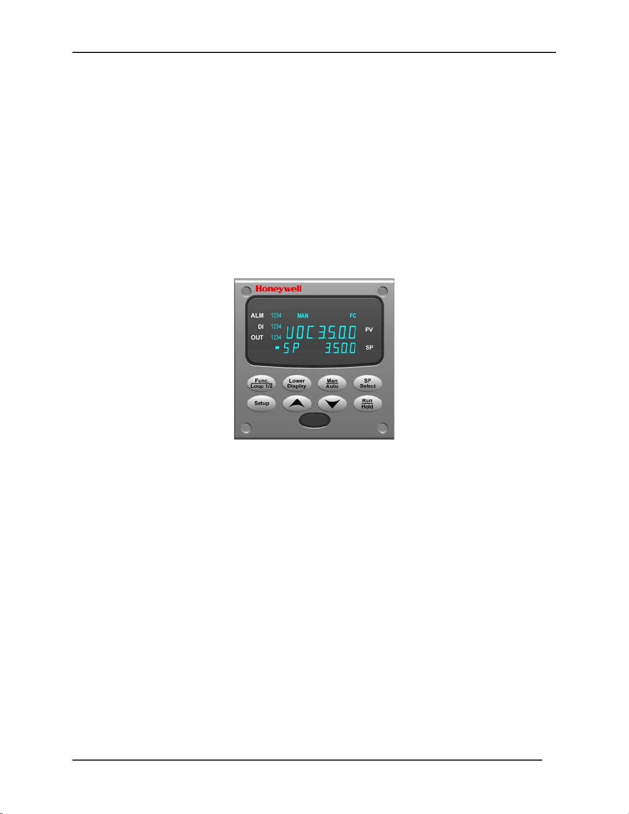
1.2 Operator Interface
Figure 1-1 UDC3500 Operator Interface
6 UDC3500 Universal Digital Controller Product Manual 9/06
Page 21
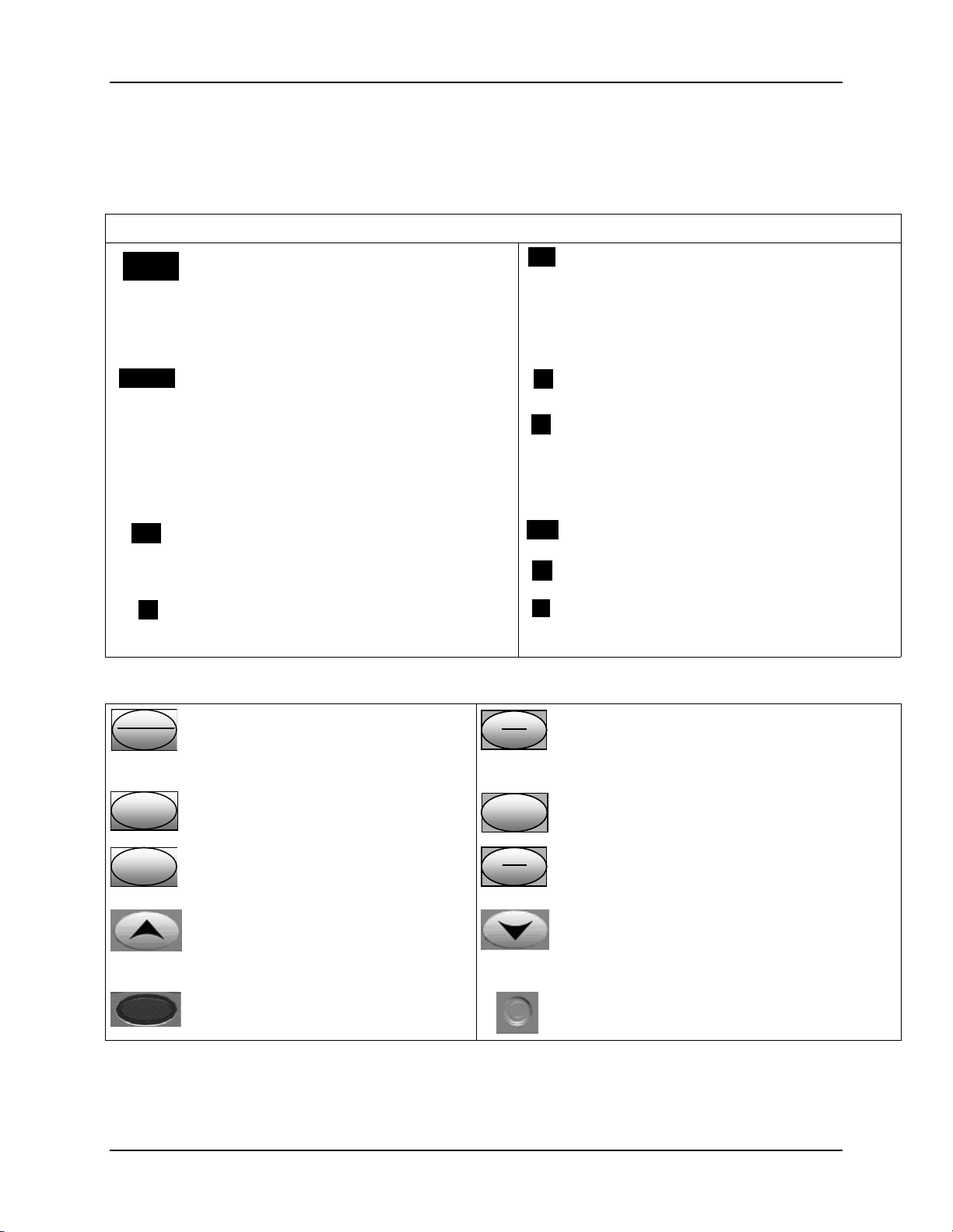
1.2.1 Function of Displays and Keys
Table 1-1 Function of Displays and Keys
Display Indicators
Introduction
3200
3500
SP 3500
SP
ALMALM
3200
DIDI
Upper display with 4 larger digits shows
Process Variable value (normal operation)
and special annunciator features. During
Configuration, the upper display provides
guidance for the operator through prompts (7
– characters)
During normal operation, the lower display
shows key-selected operating parameters
such as Output, Setpoints, Inputs, Deviation,
active Tuning Parameter Set, Timer Status, or
minutes remaining in a setpoint ramp (4
digits). During configuration, the lower display
provides guidance for the operator through
prompts (8-characters).
Indicates Alarm 1 and/or Alarm 2 conditions
exist.
Indicates Digital Input 1 and/or 2 on.
Keys and Functions
Indicates Control Relay 1 and/or 2 on.
OUT
FF
Or
Indicates either degrees Fahrenheit or
Centigrade.
CC
MAN
Or
Indicates either Manual or Auto mode.
AA
Indicates Local Setpoint #1. Also, a bar is
SPSP
lighted when the setpoint being used is shown
on the lower display.
Func
Loop 1/2
Selects functions within each
configuration group. Switches between
Loop Displays for Two Loop and
Man
Man
Man
Auto
Auto
Auto
Selects Manual or Auto mode.
Cascade units.
SetupSetup
Lower
Lower
Lower
Display
Display
Display
Scrolls through the configuration
groups.
Returns Controller to normal display
from Set Up mode. Toggles various
operating parameters for display.
Increases setpoint or output value.
Increases the configuration values or
changes functions in Configuration
mode groups.
Infrared transceiver
SP
SP
SP
Select
Select
Select
Run
Run
Run
Hold
Hold
Hold
Hold key down to cycle through configured
setpoints.
Enables Run/Hold of the SP Ramp or Program
plus Timer start.
Decreases setpoint or output value. Decreases
the configuration values or changes functions in
Configuration mode groups.
NEMA4X and IP66 screw attachment (each
corner)
9/06 UDC3500 Universal Digital Controller Product Manual 7
Page 22
Introduction
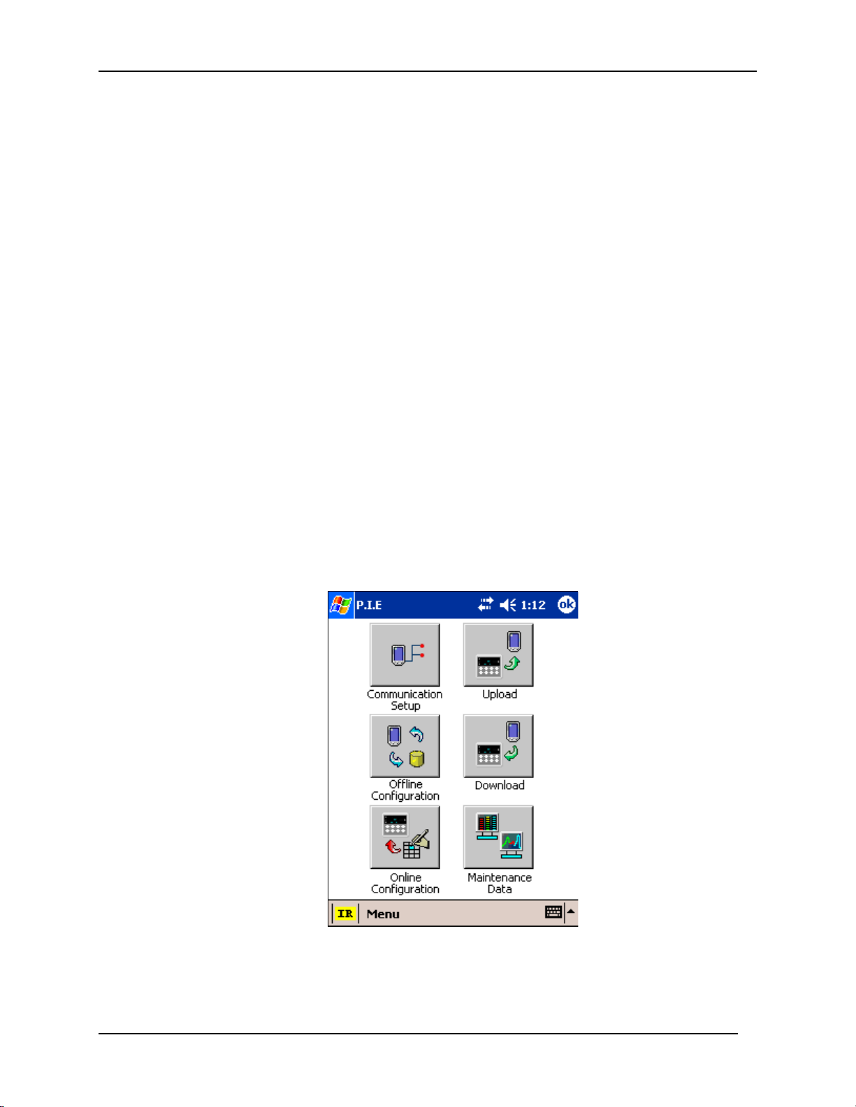
1.3 Process Instrument Explorer Software
Overview
Process Instrument Explorer (P.I.E.) lets you configure your instrument on a
desktop/laptop or Pocket PC. For details see Process Instrument Explorer Manual #5152-25-131.
Features
• Create configurations with intuitive software program running on a Pocket PC, a
Desktop or a laptop computer.
• Create/edit configurations live, just connect software to the controller via a
communications port.
• Create/edit configurations offline and download to controller later via a
communications port.
• Communication types available on every UDC3500:
Infrared (standard)
RS 485 (optional)
Ethernet (optional)
• Same port types on UDC2500 and UDC3200 allow interconnectivity.
• This software is available in English, Spanish, Italian, German and French.
Figure 1-2 Screen capture of Process Instrument Explorer
running on a Pocket PC
8 UDC3500 Universal Digital Controller Product Manual 9/06
Page 23
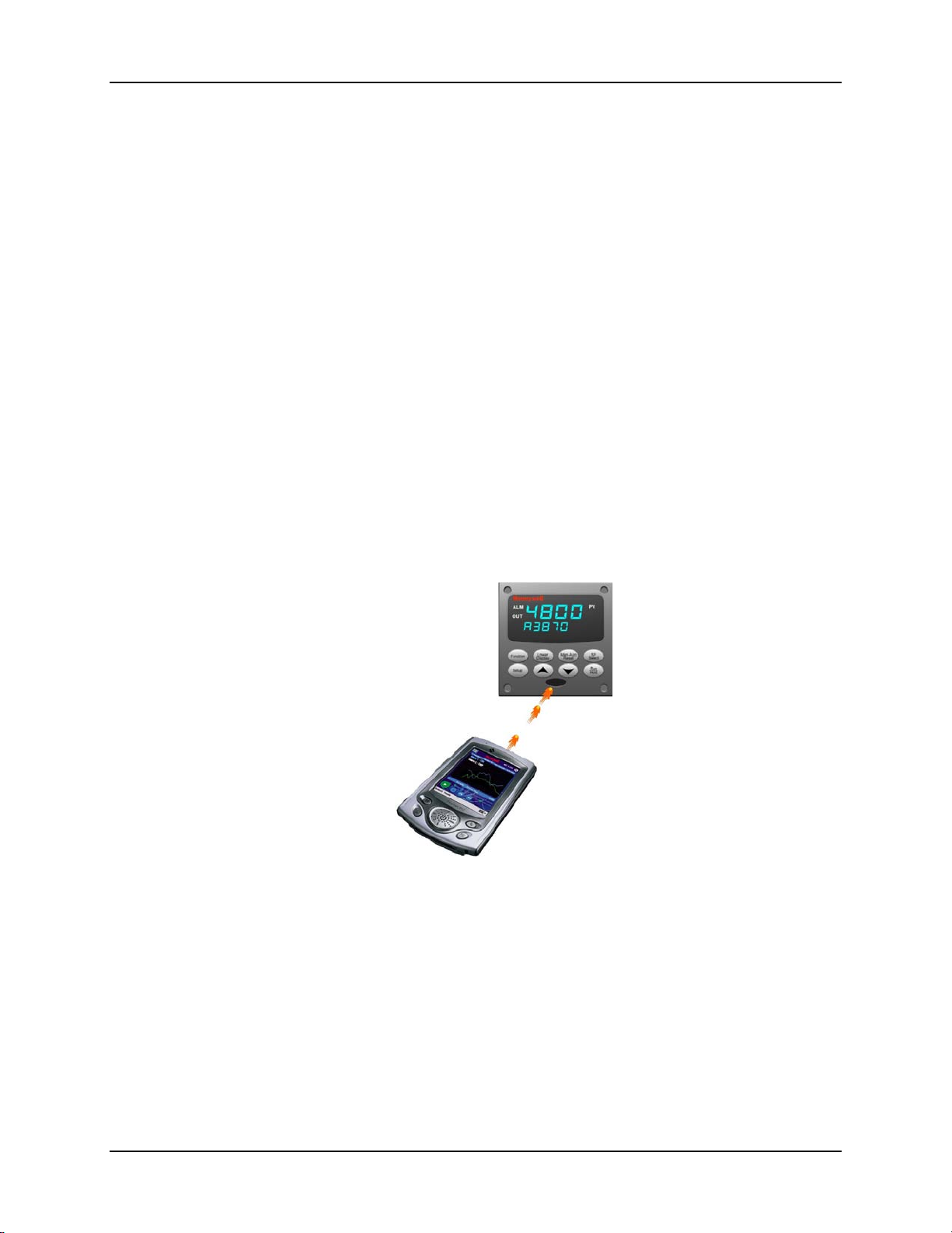
Infrared communications
The infrared connection provides a non-intrusive wireless connection with the instrument
and maintains NEMA4X AND IP66 integrity.
No need to get access to the back of the controller to communicate with the instrument,
no need to take your screw driver to wire the communication cable, no wiring mistake
possible. You can now duplicate an instrument’s configuration, upload or download a
new configuration in a matter of seconds, just by pointing your Pocket PC in the direction
of the instrument.
It takes just a few seconds to upload a configuration from an instrument. You can then
save the configuration file onto your PC or pocket PC for review, modification or
archiving. Furthermore, this software also gives you important maintenance information
on the controller: instantly, get information on the current operating parameters, digital
inputs and alarm status, identify internal or analog input problems.
Question: What if I have several controllers on the same panel? How can I be sure I am
communicating with the correct one?
Answer: The infrared port of the controller is normally “off”. You activate the infrared
port by pressing any controller’s key. You can now communicate. After 4 minutes, the
port will be shut down again. Each controller may also be assigned a different
communications address.
Introduction
Figure 1-3 Depiction of infrared communications
9/06 UDC3500 Universal Digital Controller Product Manual 9
Page 24

Introduction
1.4 CE Conformity (Europe)
This product is in conformity with the protection requirements of the following European
Council Directives: 73/23/EEC, the Low Voltage Directive, and 89/336/EEC, the EMC
Directive. Conformity of this product with any other “CE Mark” Directive(s) shall not be
assumed.
Product Classification: Class I: Permanently connected, panel-mounted Industrial
Control Equipment with protective earthing (grounding) (EN61010-1).
Enclosure Rating: This controller must be panel-mounted with the rear terminals
enclosed within the panel. The front panel of the controller is rated at NEMA4X and IP66
when properly installed.
Installation Category (Overvoltage Category): Category II (EN61010-1)
Pollution Degree: Pollution Degree 2: Normally non-conductive pollution with
occasional conductivity caused by condensation. (Ref. IEC 664-1)
EMC Classification: Group 1, Class A, ISM Equipment (EN61326, emissions), Industrial
Equipment (EN61326, immunity)
Method of EMC Assessment: Technical File (TF)
Declaration of Conformity: 51453681
Deviation from the installation conditions specified in this manual, and the special
conditions for CE conformity in Subsection 2.1, may invalidate this product’s conformity
with the Low Voltage and EMC Directives.
ATTENTION
The emission limits of EN61326 are designed to provide reasonable protection
against harmful interference when this equipment is operated in an industrial
environment. Operation of this equipment in a residential area may cause harmful
interference. This equipment generates, uses, and can radiate radio frequency
energy and may cause interference to radio and television reception when the
equipment is used closer than 30 meters (98 feet) to the antenna(e). In special
cases, when highly susceptible apparatus is used in close proximity, the user may
have to employ additional mitigating measures to further reduce the
electromagnetic emissions of this equipment.
WARNING
If this equipment is used in a manner not specified by the manufacturer, the
protection provided by the equipment may be impaired.
10 UDC3500 Universal Digital Controller Product Manual 9/06
Page 25

2.1 Overview
Introduction
Installation of the UDC3500 consists of mounting and wiring the controller according to
the instructions given in this section. Read the pre-installation information, check the
model number interpretation (Subsection 2.3) and become familiar with your model
selections, then proceed with installation.
What’s in this section?
The following topics are covered in this section.
2.1 Overview 11
Installation
2 Installation
TOPIC See Page
2.2 Condensed Specifications 13
2.3 Model Number Interpretation 17
2.4 Control and Alarm Relay Contact Information 19
2.5 Mounting 20
2.6 Wiring 22
2.7 Wiring Diagrams
Figure 2-4 Composite Wiring Diagram
Figure 2-5 Mains Power Supply
Figure 2-6 Input 1 Connections
Figure 2-7 Input 2 Connections
Figure 2-8 Input 3 Connections
Figure 2-9 HLAI Inputs 2 and 4
Figure 2-10 HLAI Inputs 3 and 5
Figure 2-11 Optional Analog Input Jumper Positions
Figure 2-12 First Current Output
Figure 2-13 Second Current Output
Figure 2-14 Output #2 – Electromechanical Relay Output
Figure 2-15 Output #2 – Solid State Relay Output
Figure 2-16 Output #2 – Open Collector Output
Figure 2-17 Output #2 – Third Current Output
Figure 2-18 Output #2 – Dual Relay Output for Time Duplex
Figure 2-19 Output #2 – Dual Relay Output for Position
Proportional or Three Position Step Control
Figure 2-20 RS-422/485 Communications Option
27
28
29
30
31
32
33
33
34
34
35
35
36
36
37
37
38
39
9/06 UDC3500 Universal Digital Controller Product Manual 11
Page 26

Installation
Figure 2-22 Ethernet Communications Option
Figure 2-23 Digital Inputs
Figure 2-24 Optional Electromechanical Relay Outputs
Figure 2-25 Transmitter Power for 4-20 mA — 2 wire
Transmitter Using Open Collector Output
Figure 2-26 Transmitter Power for 4-20 mA — 2 Wire
Transmitter Using Second Current Output
40
41
41
42
12 UDC3500 Universal Digital Controller Product Manual 9/06
Page 27

Pre-installation Information
If the controller has not been removed from its shipping carton, inspect the carton for
damage then remove the controller.
• Inspect the unit for any obvious shipping damage and report any damage due to
transit to the carrier.
• Make sure a bag containing mounting hardware is included in the carton with the
controller.
• Check that the model number shown on the inside of the case agrees with what you
have ordered.
2.2 Condensed Specifications
Honeywell recommends that you review and adhere to the operating limits listed in Table
2-1 when you install your controller.
Table 2-1 Condensed Specifications
Analog Inputs
Analog Input Signal
Failure Operation
Stray Rejection Common Mode
Digital Inputs (Four)
(Optional)
Up to three Universal analog inputs. These can easily be configured to operate as 2
Universal and 2 High Level or as 1 Universal and 4 High Level inputs.
Accuracy:
± 0.10% of full scale typical (± 1 digit for display)
Can be field calibrated to ± 0.05% of full scale typical
16-bit resolution typical
Sampling Rate: All inputs are sampled six times per second
Temperature Stability: ± 0.0075% of Full Scale span / ˚C change—typical
Input Impedance:
0-20 and 4-20 Milliampere Inputs: 250 ohms
0-10 Volt and –1 to +1 Volt Input: 200K ohms
All Others: 10 megohms
Maximum Lead Wire Resistance:
Thermocouples: 50 ohms/leg
100 ohm, 200 ohm, 500 ohm and 1000 ohm RTD: 100 ohms/leg
100 ohm Low RTD: 10 ohms/leg
Slidewire Input for Position Proportional Control (Input 3 only):
100 ohm to 1000 ohm resistive slidewire types
Herculine
Burnout Selections: Upscale, Downscale, Failsafe or None
Thermocouple Health: Good, Failing, Failure Imminent or Failed
Failsafe Output Level: Configurable 0-100% of Output range
AC (50 or 60 Hz): 120 dB (with maximum source impedance of 100 ohms) or ± 1 LSB (least
significant bit) whichever is greater with line voltage applied.
DC: 120 dB (with maximum source impedance of 100 ohms) or a ±1 LSB whichever is
greater with 120 Vdc applied.
DC (to 1 KHz): 80 dB (with maximum source of impedance of 100 ohms) or ±1 LSB
whichever is greater with 50 Vac applied.
Normal Mode
AC (50 or 60 Hz): 60 dB (with 100 % span peak-to-peak maximum)
+30 Vdc source for external dry contacts or isolated solid-state contacts. Digital Inputs are
isolated from line power, earth ground, analog inputs and all outputs.
©
Models 10260 and 11280 Slidewire Emulation
Installation
Specifications
9/06 UDC3500 Universal Digital Controller Product Manual 13
Page 28

Installation
Current and Auxiliary
Outputs
Output 2 Options
Three Relay Board
(Optional)
Specifications
Up to three Milliamp Outputs. These outputs provide a 0 to 21 mA current output into a
negative or positive grounded load or into a non-grounded load. Current outputs are isolated
from each other, line power, earth ground and all inputs. Outputs can easily be configured
via the keyboard to be 0 to 20 mA or 4 to 20 mA without field calibration and for either direct
or reverse action when used as a control output.
Any current output not being used as a control output can be used in an Auxiliary Output
mode. Auxiliary Outputs can be configured to represent any Analog Input, PV, Setpoint,
Deviation, or Control Output. The range of an Auxiliary Output can be scaled per the range
of the selected variable and can be set anywhere between 0 to 21 mA.
Resolution: 14 bits over 0 to 21 mA
Accuracy: 0.05% of full scale
Temperature Stability: 0.01% F.S./°C typical
Load Resistance: 0 to 1000 ohms
The First Current Output is a standard feature and is present on all instruments. The Second
Current Output is an option and is mutually exclusive with Ethernet Communications. The
Third Current Output is an option and is mutually exclusive with the other Output 2 Options
listed directly below.
Output 2 is a socket which may be populated with any one of the following output types:
Electromechanical Relay
SPDT contacts. Both Normally Open and Normally Closed contacts are brought out to the
rear terminals.
Resistive Load: 5 amps @ 120 Vac or 240 Vac or 30 Vdc
Inductive Load (cos
Inductive Load (L/R = 7 milliseconds): 3.5 amps @ 30 Vdc
Motor: 1/6 H.P.
Dual Electromechanical Relays
Two SPST relays. One Normally Open contact for each relay is brought out to the rear
terminals. This option must be used as the Loop 1 output for On-Off Duplex, Time Duplex,
Three Position Step Control and Position Proportional Control applications. Instruments with
this option can have a total of five relays plus one or two current outputs.
Resistive Load: 2 amps @ 120 Vac, 240 Vac or 30 Vdc
Inductive Load (cos
Inductive Load (L/R = 7 milliseconds): 1 amp @ 30 Vdc
Solid State Relay
SPST solid-state contact consisting of a triac N.O. output with zero-crossing detection.
Resistive Load: 1.0 amp @ 25°C ambient temperature and 120 or 240 Vac
0.5 amp @ 55°C ambient temperature and 120 or 240 Vac
Inductive Load: 50 VA @ 55°C ambient temperature and 120 or 240 Vac
Minimum Load: 20 milliamps
Open Collector Output
Transistor drive for powering an external relay. Isolated from earth ground and all other
circuits except the First Current Output. Internally powered @ 30 Vdc.
Note: Applying an external power supply to this output will damage the instrument.
Maximum Sink Current: 20 mA
Overload Protection: 100 mA
Third Current Output
See above.
Three SPDT contacts. Both Normally Open and Normally Closed contacts are brought out to
the rear terminals for each relay. These relays are used for Alarm outputs or for the output of
the second control loop. They may also be used as outputs for Logic Gate functions.
Resistive Load: 5 amps @ 120 Vac or 240 Vac or 30 Vdc
Inductive Load (cos
Inductive Load (L/R = 7 milliseconds): 3.5 amps @ 30 Vdc
Motor: 1/6 H.P.
ϕ
= 0.4): 3 amps @ 130 Vac or 250 Vac
ϕ
= 0.4): 1 amp @ 130 Vac or 250 Vac
ϕ
= 0.4): 3 amps @ 130 Vac or 250 Vac
14 UDC3500 Universal Digital Controller Product Manual 9/06
Page 29
Specifications
Alarm Outputs
(Optional)
Isolation (Functional)
RS422/485 Modbus
RTU
Communications
Interface (Optional)
Ethernet TCP/IP
Communications
Interface (Optional)
RS-485 and Ethernet
Transaction rates
Infrared
Communications
(Standard)
Power Consumption 24 VA maximum (90 to 264 Vac)
Power Inrush Current
Weight
A maximum of four alarm relays are available, depending upon the type and quantity of
outputs used for control purposes. Each alarm may have one or two setpoints, each of which
can be independently set as high or low alarm. Setpoints can be on any Input, Process
Variable, Deviation, Manual Mode, Failsafe, PV Rate, RSP Mode, Communication Shed, or
Output. A single adjustable hysteresis of 0.0 to 100.0% is provided. The alarm can also be
set as an ON or OFF event at the beginning of a Setpoint Program Ramp or Soak segment.
Alarm status is accessible via any communications port and is shown on the display
annunciators.
AC Power: Electrically isolated from all other inputs and outputs and earth ground to
withstand a HIPOT potential of 1900 Vdc for 2 seconds per Annex K of EN61010-1.
Analog Inputs and Outputs: Are isolated from each other and all other circuits to withstand a
HIPOT potential of 850 Vdc for 2 seconds per Annex K of EN61010-1.
Digital Inputs and Digital Outputs: Electrically isolated from all other circuits to withstand a
HIPOT potential of 850 Vdc for 2 seconds per Annex K of EN61010-1.
Relay Contacts: With a working voltage of 115/230 Vac, these are electrically isolated from
all other circuits to withstand a HIPOT potential of 345 Vdc for 2 seconds per Annex K of
EN61010-1
Baud Rate: 4800, 9600,19,200 or 38,400 baud selectable
Data Format: Floating point or integer
Length of Link:
2000 ft (600 m) max. with Belden 9271 Twinax Cable and 120 ohm termination resistors
4000 ft. (1200 m) max. with Belden 8227 Twinax Cable and 100 ohm termination resistors
Link Characteristics: Two-wire (half-duplex), multi-drop Modbus RTU protocol, 15 drops
maximum or up to 31 drops for shorter link length.
Type: 10Base-T
Length of Link: 330 ft. (100 m) maximum. Use Shielded twisted-pair, Category 5 (STP
CAT5) Ethernet cable.
Link Characteristics: Four-wire plus shield, single drop, five hops maximum
IP Address: IP Address is 10.0.0.2 as shipped from the Factory
Recommended network configuration: Use Switch rather than Hub in order to maximize
UDC Ethernet performance.
Configuration: Ethernet parameters are configured via the Process Instrument Explorer.
Email: The capability to send two different Emails is provided. These must be configured via
the Process Instrument Explorer. It is recommended that the Real Time Clock Option be
purchased for any instrument that needs to send Email.
Ethernet Communications is mutually exclusive with the Second Current Output.
Host computer must allow a minimum of 20 milliseconds between Read transactions and a
minimum of 200 milliseconds between Write transactions.
Type: Serial Infrared (SIR)
Length of Link: 3 ft. (1 m) maximum for IrDA 1.0 compliant devices
Baud Rate: 19,200 or 38,400 baud selectable
18 VA maximum (24 Vac/dc)
10A maximum for 4 ms (under operating conditions), reducing to a maximum of 265 mA (90
to 264 Vac operation) or 900 mA (24 Vac/dc operation) after one second.
CAUTION
power is supplied. Otherwise, the instruments may not start up normally due to voltage drop
from the inrush current.
3 lbs. (1.3 kg)
When applying power to more than one instrument, make sure that sufficient
Installation
9/06 UDC3500 Universal Digital Controller Product Manual 15
Page 30

Installation
Environmental and Operating Conditions
Parameter Reference Rated Operative
Ambient Temperature
Relative Humidity
Vibration
Frequency (Hz)
Acceleration (g)
Mechanical Shock
Acceleration (g)
Duration (ms))
Line Voltage (Vdc)
24 Vdc
Line Voltage (Vac)
90 to 240 Vac
24 Vac
Frequency (Hz)
(For Vac)
* The maximum moisture rating only applies up to 40 °C (104 °F). For higher temperatures, the RH specification is derated to
maintain constant moisture content.
25 ± 3 °C
77 ± 5 °F
10 to 55* 10 to 90* 5 to 90* 5 to 95*
0
0
0
0
+24 ± 1
120 ± 1
240 ± 2
24 ± 1
50 ± 0.2
60 ± 0.2
15 to 55 °C
58 to 131 °F
0 to 70
0.4
1
30
22 to 27
90 to 240
20 to 27
49 to 51
59 to 61
Limits
0 to 55 °C
32 to 131 °F
0 to 200
0.6
5
30
20 to 30
90 to 264
20 to 27
48 to 52
58 to 62
Transportation and Storage
–40 to 66 °C
–40 to 151 °F
0 to 200
0.5
20
30
- -
- -
- -
- -
- -
- -
16 UDC3500 Universal Digital Controller Product Manual 9/06
Page 31

Installation
_
_ __
_
_
2.3 Model Number Interpretation
Introduction
Write your controller’s model number in the spaces provided below and circle the corresponding
items in each table. This information will also be useful when you wire your controller.
Instructions
Select the desired key number. The arrow to the right marks the selection available.
Make the desired selections from Tables I through VI using the column below the
proper arrow. A dot ( ) denotes availability.
Key Number
_ _ _ _ _
I
-- - -_ _ _ _ _ - _
_
_ _ _
KEY NUMBER - UDC3500 Single & Dual Loop Controller
Digital Controller for use with 90 to 264Vac Power + Current Output #1 DC3500
Digital Controller for use with 24Vac/dc Power + Current Output #1 DC3501
TABLE I - Specify optional Output and/or Alarms
Output #2
Relay Outputs #3, #4
and #5
TABLE II - Communications and Software Selections
Communications
Software Selections
Loops of Control
Real-Time Clock
TABLE III - Input types can be changed in the field
Input 1
Input 2
Input 3
None
Current Output (4 to 20mA, 0 to 20 mA) (Current Output #3)
Electro Mechanical Relay (5 Amp Form C)
Solid State 1 Amp (Zero-Crossing Type)
Open Collector transistor output
Dual 2 Amp Relays (Form A) (Heat/Cool, Pos Prop, TPSC, Relays 1 & 2)
None
Three (3) E-M Relay (5 Amp Form C)
None
Current Output #2 + (4) Digital Inputs
Current Output #2 + (4) Digital Inputs + Modbus RS-485
10 Base-T Ethernet (Modbus RTU) + (4) Digital Inputs
Standard Functions, Includes Accutune
Math Option
Set Point Programming (1 Program, 20 Segments)
Set Point Programming Plus Math
HealthWatch
SPP + HealthWatch
Math + HealthWatch
SPP + Math + HealthWatch
Single Loop
2 Loops + Internal Cascade
None
Real-Time Clock (RTC)
TC, RTD, mV, 0-5V, 1-5V
TC, RTD, mV, 0-5V, 1-5V, 0-20mA, 4-20mA
TC, RTD, mV, 0-5V, 1-5V, 0-20mA, 4-20mA, -1-1V, 0-10V
Relative Humidity (Requires Input 2)
Carbon, Oxygen or Dewpoint (Requires Input 2)
None
TC, RTD, mV, 0-5V, 1-5V, 0-20mA, 4-20mA
TC, RTD, mV, 0-5V, 1-5V, 0-20mA, 4-20mA, -1-1V, 0-10V
Two HLAI instead of 1 LLAI
None
TC, RTD, mV, 0-5V, 1-5V, 0-20mA, 4-20mA
TC, RTD, mV, 0-5V, 1-5V, 0-20mA, 4-20mA, -1-1V, 0-10V
Two HLAI instead of 1 LLAI _ _3
Slidewire Input for Position Prop. (Requires Dual Relay Output)
IIIII
_ _
Description
VIIV V
Selection
Availability
0 _
C _
E _
A _
T _
R _
_ 0
_ E
0 _ _ _
1 _ _ _
2 _ _ _
3 _ _ _
_ 0 _ _
_ A _ _
_ B _ _
_ C _ _
_ D _ _
_ E _ _
_ F _ _
_ G _ _
_ _ 0 _
_ _2 _
_ _ _ 0
_ _ _ C
Availability
DC3500 3501
Selection
1 _ _
2 _ _
3 _ _
1 5 _
1 6 _
_ 0 _
_ 1 _
_ 2 _
_ 3 _
_ _0
_ _1
_ _2
_ _4
aa
9/06 UDC3500 Universal Digital Controller Product Manual 17
Page 32

Installation
TABLE IV - Options
Approvals
Tags
Future Options
TABLE V - Product Manuals
Manuals
Certificate
TABLE VI
CE (Standard)
CE, UL and CSA
None
Stainless Steel Customer ID Tag - 3 lines w/22 characters/line
None
None
None
Product Information on CD - (English) 0 _
English Manual (Hard Copy) E _
French Manual (Hard Copy) F _
German Manual (Hard Copy) G _
Italian Manual (Hard Copy) I _
Spanish Manual (Hard Copy)
None
Certificate of Conformance (F3391)
None 0
0 _ _ _ _
1 _ _ _ _
_ 0 _ _ _
_ T _ _ _
_ _ 0 _ _
_ _ _ 0 _
_ _ _ _ 0
S _
_ 0
_ C
Figure 2-1 Model Number Interpretation
18 UDC3500 Universal Digital Controller Product Manual 9/06
Page 33

2.4 Control and Alarm Relay Contact Information
Control Relays
ATTENTION
Control relays operate in the standard control mode (that is, energized when output state is on).
Table 2-2 Control Relay Contact Information
Installation
Unit Power Control Relay
Alarm Relays
ATTENTION
Alarm relays are designed to operate in a failsafe mode (that is, de-energized during alarm
sate). This results in alarm actuation when power is OFF or when initially applied, until the unit
completes self-diagnostics. If power is lost to the unit, the alarms will de-energize and thus the
alarm contacts will close.
Power
Off
On
Control Relay
Wiring
N.O. Open
N.C. Closed
N.O.
N.C.
Contact
Open
Closed
Closed
Open
Table 2-3 Alarm Relay Contact Information
Alarm Relay
Wiring
Variable NOT in Alarm State Variable in Alarm State Unit
Relay
Contact
Indicators Relay
Output #1 or #2
Indicator Status
Off
Off
On
Off
On
Indicators
Contact
Off
On
9/06 UDC3500 Universal Digital Controller Product Manual 19
N.O. Open Open
N.C. Closed
N.O. Closed Open
N.C. Open
Off
Closed
Off
Closed
Off
On
Page 34

Installation
2.5 Mounting
Physical Considerations
The controller can be mounted on either a vertical or tilted panel using the mounting kit
supplied. Adequate access space must be available at the back of the panel for installation
and servicing activities.
• Overall dimensions and panel cutout requirements for mounting the controller are
shown in Figure 2-2.
• The controller’s mounting enclosure must be grounded according to CSA standard
C22.2 No. 0.4 or Factory Mutual Class No. 3820 paragraph 6.1.5.
• The front panel is moisture rated NEMA3 and IP55 rated and can be easily upgraded
to NEMA4X and IP66. See Figure 2-3 and Table 2-4 Mounting Procedure.
Overall Dimensions
mm
inches
Max. panel thickness
19,1
0.75
9,0
0.35
92,0 + 0,8
- 0,00
3.62 + 0.03
- 0.00
Mounting Notes
Before mounting the controller, refer to the nameplate on the outside of the case and
make a note of the model number. It will help later when selecting the proper wiring
configuration.
Panel
Cutout
92,0 + 0,8
- 0,00
3.62 + 0.03
- 0.00
Figure 2-2 Mounting Dimensions (not to scale)
17,9
0.70
148,0
5.81
90,6
3.57
108,6
4.28
20 UDC3500 Universal Digital Controller Product Manual 9/06
Page 35

Mounting Method
Before mounting the controller, refer to the nameplate on the outside of the case and
make a note of the model number. It will help later when selecting the proper wiring
configuration.
Attach screws and
washers here for
water protection
Installation
Mounting clips
Mounting Procedure
Step Action
Mark and cut out the controller hole in the panel according to the dimension
1
information in Figure 2-2.
Orient the case properly and slide it through the panel hole from the front.
2
Remove the mounting kit from the shipping container and install the kit as follows:
3
• For normal installation (NEMA 3/IP55) two mounting clips are required. Insert
the prongs of the clips into the two holes in the top and bottom center of the case
• For water-protected installation (NEMA 4/IP66) four mounting clips are
required. There are two options of where to install the mounting clips:
1) Insert the prongs of the clips into the two holes on the left and right side of the
top and bottom of the case or
2) on the center on each of the four sides.
• Tighten screws to 2 lb-inch (22 N•cm) to secure the case against the panel.
CAUTION: Over tightening will cause distortion and the unit may not seal properly.
For water-protected installation (NEMA 4/IP66), install four screws with washers into
4
the four recessed areas in the corners of the front bezel (Figure 2-3). Push the point of
the screw through the center piercing the elastomeric material and then tighten screws
to 5 lb-in (56 N•cm).
Figure 2-3 Mounting Methods
Table 2-4 Mounting Procedure
9/06 UDC3500 Universal Digital Controller Product Manual 21
Page 36

Installation
2.6 Wiring
2.6.1 Electrical Considerations
Line voltage wiring
This controller is considered “rack and panel mounted equipment” per EN61010-1,
Safety Requirements for Electrical Equipment for Measurement, Control, and Laboratory
Use, Part 1: General Requirements. Conformity with 72/23/EEC, the Low Voltage
Directive requires the user to provide adequate protection against a shock hazard. The
user shall install this controller in an enclosure that limits OPERATOR access to the rear
terminals.
Mains Power Supply
This equipment is suitable for connection to 90 to 264 Vac or to 24 Vac/dc 50/60 Hz,
power supply mains. It is the user’s responsibility to provide a switch and non-time delay
(North America), quick-acting, high breaking capacity, Type F (Europe), 1/2A, 250V
fuse(s), or circuit breaker for 90-264 Vac applications; or 2 A, 125 V fuse or circuit
breaker for 24 Vac/dc applications, as part of the installation. The switch or circuit
breaker shall be located in close proximity to the controller, within easy reach of the
OPERATOR. The switch or circuit breaker shall be marked as the disconnecting device
for the controller.
Applying 90-264 Vac to an instrument rated for 24 Vac/dc will severely
damage the instrument and is a fire and smoke hazard.
When applying power to multiple instruments, make certain that sufficient current is
supplied. Otherwise, the instruments may not start up normally due to the voltage drop
caused by the in-rush current.
Controller Grounding
PROTECTIVE BONDING (grounding) of this controller and the enclosure in which it is
installed shall be in accordance with National and Local electrical codes. To minimize
electrical noise and transients that may adversely affect the system, supplementary
bonding of the controller enclosure to a local ground, using a No. 12 (4 mm2) copper
conductor, is recommended.
Control/Alarm Circuit Wiring
The insulation of wires connected to the Control/Alarm terminals shall be rated for the
highest voltage involved. Extra Low Voltage (ELV) wiring (input, current output, and
low voltage Control/Alarm circuits) shall be separated from HAZARDOUS LIVE (>30
Vac, 42.4 Vpeak, or 60 Vdc) wiring per Permissible Wiring Bundling, Table 2-5.
Electrical Noise Precautions
Electrical noise is composed of unabated electrical signals, which produce undesirable
effects in measurements and control circuits.
22 UDC3500 Universal Digital Controller Product Manual 9/06
Page 37

Digital equipment is especially sensitive to the effects of electrical noise. Your controller
has built-in circuits to reduce the effect of electrical noise from various sources. If there
is a need to further reduce these effects:
• Separate External Wiring—Separate connecting wires into bundles
(See Permissible Wiring Bundling - Table 2-5) and route the individual bundles
through separate conduit metal trays.
Use Suppression Devices—For additional noise protection, you may want to add
suppression devices at the external source. Appropriate suppression devices are
commercially available.
ATTENTION
For additional noise information, refer to document number 51-52-05-01, How to Apply Digital
Instrumentation in Severe Electrical Noise Environments.
Permissible Wiring Bundling
Table 2-5 Permissible Wiring Bundling
Bundle No. Wire Functions
1
2 Analog signal wire, such as:
3
Installation
• Line power wiring
• Earth ground wiring
• Line voltage control relay output wiring
• Line voltage alarm wiring
• Input signal wire (thermocouple, 4 to 20 mA, etc.)
• 4-20 mA output signal wiring
Digital input signals
• Low voltage alarm relay output wiring
• Low voltage wiring to solid state type control circuits
• Low voltage wiring to open collector type control circuits
9/06 UDC3500 Universal Digital Controller Product Manual 23
Page 38

Installation
2.7 Wiring Diagrams
Identify Your Wiring Requirements
To determine the appropriate diagrams for wiring your controller, refer to the model
number interpretation in this section. The model number of the controller is on the
outside of the case.
Output Functionality and Restrictions
Table 2-6 and Table 2-7 show the control functionality and number of alarms that are
available based upon the installed outputs quantity and type. First, use the left-most
column to find the Control Output Algorithm desired for your instrument. Then use the
second column to find the Output 2 Option selection installed in your instrument. The
rest of the columns will then show how the instrument delivers your desired Output
functionality and the quantity of alarms available.
In Table 2-6, “HEAT” is used as meaning Loop 1 Control Output #1 and “COOL” is
used as meaning Loop 1 Control Output #2. When Position Proportional or Three
Position Step Control (TPSC) is configured, then “HEAT” means OPEN while “COOL”
means CLOSE.
In Table 2-7, “Loop 2 HEAT” is used as meaning Loop 2 Control Output #1 and “Loop 2
COOL” is used as meaning Loop 2 Control Output #2.
See Figure 2-4 Composite Wiring Diagram, for information on where the customer
terminals are for all of these outputs and alarms.
ATTENTION
The selection for Loop 1 Output takes precedence over the selection for Loop 2 Output.
For example, if you select the Loop 1 Output Algorithm as Current Duplex 50%, then
you cannot have Current Duplex 50% as the Output Algorithm for Loop 2.
The Output 2 option shown in these tables as “Single Relay” can be any of the
following selections: Electro-Mechanical Relay, Solid-State Relay or Open Collector
Output.
If the controller is configured to use the same relay for more than one function, then the
following priority is used to determine how the relay functions: Control Outputs take
precedence over Alarms, which in turn take precedence over Time/Events, which in turn
take precedence over Logic Gate Outputs.
For example, if you select the Loop 2 Output Algorithm as Time Simplex (which uses
Relay 3), enable Alarm 3 (which also uses Relay 3) and configure a Logic Gate to use
Relay 3, then the instrument will use Relay #3 to perform the Time Simplex output and
ignore the Alarm and Logic Gate functions.
24 UDC3500 Universal Digital Controller Product Manual 9/06
Page 39

Output Alg.
Selection
Time Simplex
or ON-OFF
Simplex
Time Duplex or
ON-OFF
Duplex or
TPSC or
Position
Proportional **
Current
Simplex
Current Duplex
100 %
1st Current
Output =
COOL and
HEAT
Current Duplex
50 % ***
Cur #1 = HEAT
Cur #2 or #3 =
COOL
Current/Time
First Current
Out = COOL
Time = HEAT
Time/Current
Time = COOL
First Current
Out = HEAT
Installation
Table 2-6 Single or Cascade Loop Controller – Loop 1 Output Functionality
and Restrictions
Output #2
Option
Single Relay HEAT NUL1 NUL1 Alarm 3 Alarm 2 Alarm 1
Third Current Output N/A N/A N/A N/A N/A N/A
Dual Relay HEAT NUL1 NUL1 Alarm 3 Alarm 2 Alarm 1
None N/A N/A N/A N/A N/A N/A
Single Relay N/A N/A N/A N/A N/A N/A
Third Current Output N/A N/A N/A N/A N/A N/A
Dual Relay HEAT and
None N/A N/A N/A N/A N/A N/A
Single Relay Alarm 4 HEAT NUL1 Alarm 3 Alarm 2 Alarm 1
Third Current Output NUL1 HEAT NUL1 Alarm 3 Alarm 2 Alarm 1
Dual Relay Alarm 4 HEAT NUL1 Alarm 3 Alarm 2 Alarm 1
None N/A HEAT NUL1 Alarm 3 Alarm 2 Alarm 1
Single Relay Alarm 4 HEAT and
Third Current Output NUL1 HEAT and
Dual Relay Alarm 4 HEAT and
None N/A HEAT and
Single Relay Alarm 4 HEAT COOL Alarm 3 Alarm 2 Alarm 1
Third Current Output NUL1 *** HEAT COOL *** Alarm 3 Alarm 2 Alarm 1
Dual Relay Alarm 4 HEAT COOL Alarm 3 Alarm 2 Alarm 1
None N/A HEAT COOL Alarm 3 Alarm 2 Alarm 1
Single Relay HEAT COOL NUL1 Alarm 3 Alarm 2 Alarm 1
Third Current Output N/A N/A N/A N/A N/A N/A
Dual Relay HEAT COOL NUL1 Alarm 3 Alarm 2 Alarm 1
None N/A N/A N/A N/A N/A N/A
Single Relay COOL HEAT NUL1 Alarm 3 Alarm 2 Alarm 1
Third Current Output N/A N/A N/A N/A N/A N/A
Dual Relay COOL HEAT NUL1 Alarm 3 Alarm 2 Alarm 1
None N/A N/A N/A N/A N/A N/A
Function of
Output #2
COOL
1st Current
Output
NUL1 NUL1 Alarm 3 Alarm 2 Alarm 1
COOL
COOL
COOL
COOL
2nd Current
Output *
NUL1 Alarm 3 Alarm 2 Alarm 1
NUL1 Alarm 3 Alarm 2 Alarm 1
NUL1 Alarm 3 Alarm 2 Alarm 1
NUL1 Alarm 3 Alarm 2 Alarm 1
Relay #3 Relay #4 Relay #5
TPSC = Three Position Step Control
N/A = The output form or the individual output is N
Output #2 Option selection.
NUL1 = N
9/06 UDC3500 Universal Digital Controller Product Manual 25
ot Used on Loop 1 – This particular output is not used for the selected Loop 1 Output
Type, But it may be used for the Second Loop Output Type. Refer to the selection made in
Table 2-7. Any current output not used as a Control Output for either loop may be used as
an Auxiliary Output.
ot Available, not operable or is not used for this
Page 40

Installation
Loop 2 Output
Algorithm
Selection
ON-OFF Simplex
Table 2-7 Dual Loop Controller – Loop 2 Output Functionality and
Restrictions
Output #2
Option
Third Current
Output
Function of
Output #2
NUL2 NUL2 NUL2 Loop 2
1st Current
Output
2nd Current
Output *
Relay #3 Relay #4 Relay #5
HEAT
Alarm 2 Alarm 1 Time Simplex or
ON-OFF Duplex
100 %
Second or Third
Current Out =
COOL and HEAT
50 % ***
Second Current =
HEAT
Third Current =
COOL
Second or Third
Current = COOL
Time = HEAT
All Other
Options
Third Current
Output
All Other
Options
Third Current
Output
All Other
Options
Third Current
Output
All Other
Options
Third Current
Output
All Other
Options
Third Current
Output
All Other
Options
NUL2 NUL2 NUL2 Loop 2
HEAT
NUL2 NUL2 NUL2 Loop 2
HEAT
NUL2 NUL2 NUL2 Loop 2
HEAT
Loop 2 HEAT NUL2 NUL2 Alarm 3 Alarm 2 Alarm 1 Current Simplex
NUL2 NUL2 Loop 2
HEAT
Loop 2 HEAT
and COOL
NUL2 NUL2 Loop 2
Loop 2 HEAT NUL2 Loop 2
N/A2 N/A2 N/A2 N/A2 N/A2 N/A2
Loop 2 COOL NUL2 NUL2 Loop 2
NUL2 NUL2 Loop 2
NUL2 NUL2 Alarm 3 Alarm 2 Alarm 1 Current Duplex
HEAT and
COOL
COOL
COOL
Alarm 3 Alarm 2 Alarm 1
Alarm 3 Alarm 2 Alarm 1
Alarm 3 Alarm 2 Alarm 1 Current Duplex
HEAT
Loop 2
HEAT
Alarm 2 Alarm 1
Loop 2
COOL
Loop 2
COOL
Alarm 2 Alarm 1 Current/Time
Alarm 2 Alarm 1
Alarm 1 Time Duplex or
Alarm 1
Time = COOL
Second or Third
Current = HEAT
NUL2 = N ot Used on Loop 2 – This particular output is not used for the selected Second Loop
N/A2 = Current Duplex 50% is N
* The Second Current Output and Ethernet Communications are mutually exclusive.
** TPSC and Position Proportional are available only on Loop 1.
*** Current Duplex 50% is available only on Loop 1 or Loop 2, it cannot be used on both loops. If the
Second Current Output is not present, then the Third Current Output is used as Loop 1 COOL output.
26 UDC3500 Universal Digital Controller Product Manual 9/06
Third Current
Output
All Other
Options
Output type, but it may be used for the First Loop Output type. Refer to the selection made
in Table 2-6. Any Current Output not used as a Control Output on either loop may be
configured as an Auxiliary Output.
installed.
Loop 2 HEAT NUL2 NUL2 Loop 2
COOL
NUL2 NUL2 Loop 2
HEAT
ot Available on Loop 2 unless the Third Current Output is
Loop 2
COOL
Alarm 2 Alarm 1 Time/Current
Alarm 2 Alarm 1
Page 41

Wiring the Controller
Using the information contained in the model number, select the appropriate wiring
diagrams from the composite wiring diagram below. Refer to the individual diagrams
listed to wire the controller according to your requirements.
Installation
8
10
1
9
2
3
L1
11
L2/N
12
4
13
5
14
6
15
7
16
8
17
18
9
See table for callout details
19
20
21
22
23
24
25
26
27
7
28
29
30
31
32
33
34
35
36
9
Figure 2-4 Composite Wiring Diagram
Callout Details
1 AC/DC Line Voltage Terminals. See Figure 2-5.
2 First Current Output Terminals. See Figure 2-12.
6
5
4
3 Output 2 Option Terminals. See Figure 2-14 through Figure 2-19.
4 Input #1 Terminals. See Figure 2-6.
5 Input #2 Terminals. See Figure 2-7.
Dual HLAI Inputs #2 and #4 Terminals. See Figure 2-9 and Figure 2-11.
6 Input #3 Terminals. See Figure 2-8.
Dual HLAI Inputs #3 and #5 Terminals. See Figure 2-10 and Figure 2-11.
7 Digital Inputs Terminals. See Figure 2-23.
8 Optional Relays Terminals (Relays 3, 4 and 5). See Figure 2-24.
9 Optional Interface
Second Current Output Terminals. See Figure 2-13.
RS-485 Communications Terminals. See Figure 2-20.
Ethernet Communications Terminals. See Figure 2-22.
9/06 UDC3500 Universal Digital Controller Product Manual 27
Page 42

Installation
Voltage
Voltage
Earth
Earth
1
1
Ground
3
3
AC/DC
AC/DC
Line
Line
1
1
PROTECTIVE BONDING (grounding) of this controller and the enclosure in which it is
PROTECTIVE BONDING (grounding) of this controller and the enclosure in which it is
installed, shall b e in accordance w ith National and lo ca l ele c trica l co des. To minimize
installed, shall b e in accordance w ith National and lo ca l ele c trica l co des. To minimize
electrical noise and transients that may adversely affect the system, supplementary
electrical noise and transients that may adversely affect the system, supplementary
bonding of the controller enclosure to local ground using a No. 12 (4 mm
bonding of the controller enclosure to local ground using a No. 12 (4 mm
conductor is recommended. Before powering the controller, see “Prelimnary Checks” in
conductor is recommended. Before powering the controller, see “Prelimnary Checks” in
this section of the Product Manual.
this section of the Product Manual.
2
2
Ground
Hot
Hot
Neutral
Neutral
L1
L1
L2/N
L2/N
4
4
5
5
6
6
7
7
8
8
9
9
10
10
11
11
12
12
13
13
14
14
15
15
16
16
17
17
18
18
19
19
20
20
21
21
22
22
23
23
24
24
25
25
26
26
27
27
2
2
) copper
) copper
28
28
29
29
30
30
31
31
32
32
33
33
34
34
35
35
36
36
2
2
It is the user’s responsibility to provide a swit ch and non-time delay (North America),
It is the user’s responsibility to provide a swit ch and non-time delay (North America),
quick-acting, high breaking capacity, Type F (Europe), 1/2A, 250V fuse(s), or circuit-
quick-acting, high breaking capacity, Type F (Europe), 1/2A, 250V fuse(s), or circuitbreaker for 90-264 Vac applications; or 2 A, 125 V fuse or circuit breaker for 24 Vac/dc
breaker for 90-264 Vac applications; or 2 A, 125 V fuse or circuit breaker for 24 Vac/dc
applications, as part of the installation.
applications, as part of the installation.
3
3
Applying 90-264 Vac to an instrument rated for 24 Vac/dc will severely
Applying 90-264 Vac to an instrument rated for 24 Vac/dc will severely
damage the instrument a nd i s a fire and smoke hazard.
damage the instrument a nd i s a fire and smoke hazard.
Figure 2-5 Mains Power Supply
28 UDC3500 Universal Digital Controller Product Manual 9/06
Page 43

Ω
Ω
Input #2
Input #1
Thermocouple
Thermocouple
Use Thermocouple
Use Thermocouple
extension wire only
extension wire only
3
1
3 2
0-10 Volts or –1 to 1 Volts
+
+
1
1
100K
100K
2
Volt
Volt
source
source
2
1
3
100K
100K
3
3
–
–
22
34
23
35
24
36
22
34
23
35
24
36
R
R
+
+
–
–
R
R
+
+
–
–
Milliamps
Milliamps
Xmitter
Xmitter
–
–
+
+
RTD
RTD
Power
Power
Supply
Supply
250
250
Installation
Carbon, Oxygen, Millivolt or Volts
except 0 to 10 Volts or –1 to 1 Volts
22
34
R
R
mV or
23
35
+
+
–
–
24
36
R
R
22
34
1
3
–+
–+
23
35
24
36
+
+
–
–
mV or
+
+
Volt
Volt
source
source
–
–
Thermocouple Differential
Thermocouple Differential
Use Thermocouple
Use Thermocouple
extension wire only
extension wire only
+
+
–
–
2
4
–
–
5
+
+
22
34
23
35
24
36
R
R
+
+
–
–
22
R
34
R
23
+
35
+
–
–
24
36
1
Remove the “R” terminal screw and install the C/J Sensor in its place. Connect the t ang to the “−“ termin al.
This controller does not produce a steady current for burnout detection. For that reason, when a
2
thermocouple is used in parallel with another instrument, it may be desirable to configure the burnout
selection for this controller to “NOFS” and use the burnout current from the other instrument to also drive
this controller. The Failsafe Output must be set to ensure proper operation when the thermocouple fails.
The 250 ohm resistor for milliamp inputs or the voltage divider for 0 to10 Volt or –1 to 1Volt inputs are
3
supplied with the controller when those inputs are specified. These items must be installed prior to start up
when the controller is wired. For 0-20 mA, -1 to 1 Volt and 0-10 Volt applications, the resistor should be
located at the transmitter terminals if Burnout detection is desi red.
Splice and tape this junction between the two thermocouples. This junction may be located anywhere
4
between the thermocouples and the instrument terminals, it does not need to be close to the other
thermocouple junctions. Both thermocouples must be of the same type. For the highest accuracy, the
thermocouples should be matched or, preferably, made from the same batch of wire.
The millivolt values for the Thermocouple Differential Input are for a pair of J thermocouples at an ambient
5
temperature mean of 450°F / 232°C. Cold Junction Compensation is not required for this input type.
Figure 2-6 Input 1 Connections
9/06 UDC3500 Universal Digital Controller Product Manual 29
Page 44

Installation
Ω
Ω
Input #2
Input #2
Millivolt or Volts except
RTD
Thermocouple
Thermocouple
Use Thermocouple
Use Thermocouple
extension wire only
extension wire only
3 2
22
R
31
23
32
24
33
R
+
+
–
–
3
1
0-10 Volts or –1 to 1 Volts
22
R
31
23
32
24
33
R
+
+
–
–
+
+
1
1
100K
100K
0 – 10
Volt
Volt
source
source
1
Remove the “R” terminal screw and install the C/J Sensor in its place. Connect the t ang to the “−“ termin al.
This controller does not produce a steady current for burnout detection. For that reason, when a
2
thermocouple is used in parallel with another instrument, it may be desirable to configure the burnout
selection for this controller to “NOFS” and use the burnout current from the other instrument to also drive
this controller. The Failsafe Output must be set to ensure proper operation when the thermocouple fails.
2
2
1
3
100K
100K
3
3
–
–
RTD
Milliamps
Milliamps
–
–
Xmitter
Xmitter
+
+
250
250
Power
Power
–+
–+
Supply
Supply
0 to 10 Volts or –1 to 1 Volts
source
22
31
R
R
23
32
+
+
–
–
24
33
R
R
22
31
1
3
23
32
24
33
+
+
–
–
source
mV or
mV or
+
+
Volt
Volt
source
source
–
–
Thermocouple Differential
Thermocouple Differential
Use Thermocouple
Use Thermocouple
extension wire only
extension wire only
+
+
–
–
2
4
–
–
5
+
+
22
31
23
32
24
33
R
R
+
+
–
–
22
R
31
R
23
+
32
+
–
–
24
33
The 250 ohm resistor for milliamp inputs or the voltage divider for 0 to10 Volt or –1 to 1Volt inputs are
3
supplied with the controller when those inputs are specified. These items must be installed prior to start up
when the controller is wired. For 0-20 mA, -1 to 1 Volt and 0-10 Volt applications, the resistor should be
located at the transmitter terminals if Burnout detection is desi red.
Splice and tape this junction between the two thermocouples. This junction may be located anywhere
4
between the thermocouples and the instrument terminals, it does not need to be close to the other
thermocouple junctions. Both thermocouples must be of the same type. For the highest accuracy, the
thermocouples should be matched or, preferably, made from the same batch of wire.
The millivolt values for the Thermocouple Differential Input are for a pair of J thermocouples at an ambient
5
temperature mean of 450°F / 232°C. Cold Junction Compensation is not required for this input type.
Figure 2-7 Input 2 Connections
30 UDC3500 Universal Digital Controller Product Manual 9/06
Page 45

Installation
Ω
Ω
Input #2
Input #3
Thermocouple RTD
Thermocouple RTD
Use Thermocouple
Use Thermocouple
extension wire only
extension wire only
0-10 Volts or –1 to 1 Volts
Volt
Volt
source
source
22
R
28
22
28
23
29
24
30
23
29
24
30
R
+
+
–
–
R
R
+
+
–
–
Milliamps
Milliamps
Xmitter
Xmitter
–
–
+
+
250
250
Power
Power
–+
–+
Supply
Supply
Slidewire Input
Slidewire Input
3
1
3 2
+
+
1
1
100K
100K
2
2
1
3
100K
100K
3
3
–
–
(for Position Proportional Control or Three Position Step Contro
(for Position Proportional Control or Three Position Step Control)
Millivolt or Volts except
0 to 10 Volts or –1 to 1 Volts
source
22
R
28
R
2324+
2930+
–
–
22
R
28
R
1
3
23
29
24
30
+
+
–
–
source
mV or
mV or
+
+
Volt
Volt
source
source
–
–
Thermocouple Differential
Thermocouple Differential
Use Thermocouple
Use Thermocouple
extension wire only
extension wire only
+
+
–
–
2
4
–
–
5
+
+
22
28
23
29
24
30
R
R
+
+
–
–
22
R
28
R
23
+
29
+
–
–
24
30
4
46
Open
Open
Wiper
Wiper
Close
Close
1
Remove the “R” terminal screw and install the C/J Sensor i n its pl ace. Connect the tang to the “
1
The 250 ohm resistor for milliamp inputs or the voltage divider for 0-10 Volt inputs are supplied
with the controller when those inputs are specified. These items must be installed prior to start
This controller does not produce a steady current for burnout detection. For that reason, when a
2
up when the controller is wire d. For 0-20 mA applications, the resistor should be located at the
thermocouple is used in parallel with another instrument, it may be desirable t o configure the burnout
transmitter terminals if Burnout detec tion is desired.
selection for this controller to “NOFS” and use the burnout current from the other inst rument to als o drive
this controller. The Failsafe Output must be set to ensure proper operation when the thermocouple fails.
2
Splice and tape this junction between the two thermocouples. Thi s junction may be located
anywhere between the thermocouples and the instrument terminals, it does not need to be close
The 250 ohm resistor for milliamp inputs or the voltage divider for 0 to10 Volt or –1 to 1Volt inputs are
3
to the other thermocou ple junctions. Both thermocouples must be of the same type. For bes t
supplied with the controller when those inputs are specified. These items must be i nstalled prior to start up
accuracy, the two thermocouples should be matched or, preferably , made from the same batch
when the controller is wired. For 0-20 mA, -1 to 1 Volt and 0-10 Volt applications, the resistor should be
of wire.
located at the transmitter terminals if B u rnout detection is desired.
This controller does not produce a steady current for burnout detection. For that rea son, when a
3
Splice and tape this junction between the two thermocouples. This junction may be located anywhere
4
thermocouple is used in parallel with another instrument, it m ay be desirable to configure the
between the thermocouples and the instrument terminals, it does not need to be close to the ot her
burnout selection for this controller to “NOFS” and use the burnout current from the other
thermocouple junctions. Both thermocouples m ust be of the same type. For the highest accuracy, the
instrument to also drive this controller.
thermocouples should be matched or, preferably, made from the same batch of wire.
The millivolt values for the Thermocouple Differenti al I nput are for a pair of J thermocouples at an ambient
5
temperature mean of 450°F / 232°C. Cold Junction Compensation is not required f or this i nput type.
Input 3 is used to measure the Slidewire Input for Position Proportional Control.
6
22
28
2324+
2930+
R
R
–
–
“ terminal.
−
xxxx
Figure 2-8 Input 3 Connections
9/06 UDC3500 Universal Digital Controller Product Manual 31
Page 46

Installation
Ω
A
TTENTION:
Check Input 2 jumper when
replacing single input with two
HLAI.
0-5V or 1-5V Connections
Input 4 Source
Input 2 Source
1
The 250 ohm resistors for milliamp inputs are supplied with the controller when those inputs are specified.
These items must be installed prior to start up when the controller is wired. For 0-20 mA applications, the
resistor sho uld be located at the transmitter termina ls if Burnout detection is de sired.
+
–
+
–
10
L1
11
12
L2/N
13
4
14
5
15
6
16
7
17
8
18
9
28
19
29
20
30
21
31
22
32
23
33
24
34
25
35
26
36
27
+
+
–
0-20 or 4-20mA Connections
High Level
Analog Input
Connections
See Below
Transmitter 4
31
31
32
33
+
+
–
Transmitter 2
+
–
+
–
+
1
Ω
250
250
1
–
32
33
+
+
–
Power
Supply
Figure 2-9 HLAI Inputs 2 and 4 Connections
See Figure 2-11 for Jumper Positions.
32 UDC3500 Universal Digital Controller Product Manual 9/06
Page 47

Ω
A
2
TTENTION:
Check Input 3 jumper when
replacing single input with two
HLAI.
0-5V or 1-5V Connections
Input 5 Source
Input 3 Source
+
–
+
–
Installation
L1
11
L2/N
12
4
13
5
14
6
15
7
16
8
17
18
9
29
20
30
21
31
22
32
23
33
24
34
25
35
26
36
27
0-20 or 4-20mA Connections
28
19
10
+
+
–
High Level
Analog Input
Connections
See Below
Transmitter 5
28
28
29
30
+
+
–
Transmitter 3
+
–
+
–
+
1
Ω
250
250
1
–
29
30
+
+
–
Power
Supply
See Figure 2-11 for Jumper Positions.
Jumper
Location
Jumper
Position
Input Types
Available
1
The 250 ohm resistors for milliamp inputs are supplied with the controller when those inputs are specified.
These items must be installed prior to start up when the controller is wired. For 0-20 mA applications, the
resistor should be located at the transmitter terminals if Burnout detection is desired.
Figure 2-10 HLAI Inputs 3 and 5 Connections
Top of unit
W1
W2
nd
2
Input becomes HLAI Inputs 2 & 4
rd
3
Input becomes HLAI Inputs 3 & 5
W1
W2
W1
W2
Two HLAI
3rd Input PWA
nd Input PWA
MCU/Input PWA
Single Input
Thermocouple, RTD, Volt, Millivolt,
Milliamp, Radiamatic and
(Input 3 only) Slidewire
Figure 2-11 Optional Analog Input Jumper Positions
9/06 UDC3500 Universal Digital Controller Product Manual 33
Page 48

Installation
_
28
29
30
31
32
33
34
35
36
+
Output Load
0 - 1000 ohms
1
The First Current Output is standard on all instruments.
Current Output
0-20 or 4-20 mA
–
1
L1
L2/N
4
5
6
7
8
9
Figure 2-12 First Current Output
See Table 2-6 and Table 2-7 for other information about output types.
19
20
21
22
1
23
24
+
Output Load
0 – 1000 ohms
25
26
27
Connect shield
to ground at one
end only.
1
The Second Current Output is mutually exclusive with Ethernet
Communications.
Figure 2-13 Second Current Output
See Table 2-6 and Table 2-7 for other information about output types.
34 UDC3500 Universal Digital Controller Product Manual 9/06
Page 49

Installation
28
L1
L2/N
4
5
6
7
Load
Supply
Power
Electromechanical relays are rated at 5 Amps @ 120 Vac or 240 Vac or 30 Vdc.
1
Customer should size fuses accordingly. Use Fast Blo fuses only.
Relay Load
7 (N.C.) or 9 (N.O.)
1
To terminal
8
9
N.C.
N.O.
29
30
31
32
33
34
35
36
Figure 2-14 Output #2 – Electromechanical Relay Output
See Table 2-6 and Table 2-7 for other information about output types.
28
L1
L2/N
4
5
1
Dummy Resistor
Load
Supply
Power
If the load current is less than the minimum rated value of 20 mA, then there may be residual voltage across both
1
ends of the load even if the relay is turned off. Use a dummy resistor as shown to counteract this. The total
current through the resistor and the the load must exceed 20 mA. Solid State Relays are zero-crossing type.
Solid State relays are rated at 1 Amp at 25°C and derated linearly to 0.5 Amp at 55°C. Customer should size
2
fuse accordingly. Use Fast Blo fuses only.
Relay Load
2
6
7
8
N.O.
9
29
30
31
32
33
34
35
36
Figure 2-15 Output #2 – Solid State Relay Output
See Table 2-6 and Table 2-7 for other information about output types.
9/06 UDC3500 Universal Digital Controller Product Manual 35
Page 50

Installation
28
29
30
31
32
33
34
35
36
Customer Supplied
Electromechanical relay
+
–
Customer Supplied
Solid-State relay
1
CAUTION
Open collector outputs are internally powered at +30 Vdc. Connecting an external
power supply will damage the controller.
L1
L2/N
4
5
6
+
–
7
8
9
+
OC Output
–
1
Figure 2-16 Output #2 – Open Collector Output- Third
See Table 2-6 and Table 2-7 for other information about output types.
28
29
30
31
32
33
34
35
Output Load
+
Current Output
0-20 or 4-20 mA
L1
L2/N
4
5
6
7
8
0 - 1000 ohm s
–
9
36
Figure 2-17 Output #2 – Third Current Output
See Table 2-6 and Table 2-7 for other information about output types.
36 UDC3500 Universal Digital Controller Product Manual 9/06
Page 51

28
Installation
L1
L2/N
4
5
6
Cool Relay Load
Load
1
Power
Supply
1
Dual Electromechanical relays are rated at 2 Amps @120 Vac or 240 Vac or
Heat Relay Load
7
8
9
Out Relay #2
N.O.
Out Relay #1
N.O.
30 Vdc. Customer should size fuses accordingly. Use Fast Blo fuses only.
29
30
31
32
33
34
35
36
Figure 2-18 Output #2 – Dual Relay Output for Time Duplex
See Table 2-6 and Table 2-7 for other information about output types.
28
Motor
Power
Supply
Motor
L2/N
L1/Hot
L1
L2/N
4
5
Close (CCW)
Open (CW)
6
7
8
9
Out Relay #2
N.O.
Out Relay #1
N.O.
29
30
31
32
33
34
35
36
1
2
1
Dual Electromechanical relays are rated at 2 Amps @120 Vac or 240 Vac or
30 Vdc. Customer should size fuses accordingly. Use Fast Blo fuses only.
See Input 3 Wiring Diagram for Slidewire Connections.
2
Figure 2-19 Output #2 – Dual Relay Output for Position Proportional or
Three Position Step Control
See Table 2-6 and Table 2-7 for other information about output types. See Figure 2-8 for
Slidewire connections.
9/06 UDC3500 Universal Digital Controller Product Manual 37
Page 52

Installation
4 SHLD
UDC3500
SHLD
COMMUNICATION MASTER
SHLD D– (A)
D+ (B)
1
2
26 D+ (B)
27 D– (A)
Do not run the communications lines in the same conduit as AC power.
1
Use shielded twisted pair cables (Belden 9271 Twinax or equivalent).
2
D+
D–
TO OTHER
COMMUNICATION
CONTROLLERS
D+D–
120 OHMS ON LAST LEG
120 OHMS
Connect shield
to ground at one
end only.
Figure 2-20 RS-422/485 Communications Option Connections
RS-422/485 connections must be “daisy-chained,” T-drop connections are not allowed.
10
11
L1
12
L2/N
13
4
14
5
15
6
16
7
17
8
9
18
Tie Wraps (2)
19
20
21
22
23
24
25
26
27
28
Ethernet
29
30
31
32
33
Ethernet
Cable To
34
Hub or
35
36
24
27
Figure 2-21 Ethernet Communications Option with Adaptor Board
Instruments equipped with the Ethernet Communications Option come with an Ethernet
Adaptor Kit. To use this kit, first remove the four screws on your instrument from
Terminal Block positions 24 through 27. Place the Ethernet Adaptor Board on to the
terminal block as shown and then secure it in place with the four long screws provided in
the kit. Route the long wire on the Ethernet Adaptor Board over to Terminal #4 on your
38 UDC3500 Universal Digital Controller Product Manual 9/06
Page 53

Installation
instrument. The RJ-45 connector on the Ethernet Adaptor Board will allow you to use a
straight-through cable to connect the controller to a MDI Compliant Hub or Switch.
Alternatively, you may use a crossover cable to connect your controller directly to a PC,
which is useful for commissioning purposes. Use only Category 5 (STP CAT5) shielded
twisted-pair Ethernet cables. For strain relief, secure your Ethernet cable to the controller
with the tie wraps included in the kit using the holes in the bottom controller flange.
4 SHLD
COMMUNICATION MASTER
TXD +TXD -SHLD
RXD -
24 RXD +
25 RXD -
1
2
3
4
26 TXD +
27 TXD -
Do not run the communications lines in the same conduit as AC
power. Direct connection to a PC may require the use of an
Ethernet cross-over cable.
Use Shielded twisted-pair, Category 5 (STP CAT5) Ethernet cable.
Use Switch rather than Hub to maximize performance.
Ethernet Communications is mutually exclusive with the Second Current
Output.
3
RXD +
1
2
Figure 2-22 Ethernet Communications Option without Adaptor Board
If you would rather wire your UDC to your Ethernet connection without using the
Ethernet Adaptor Board, then Figure 2-22 and Table 2-8 show the connections for a
UDC to a MDI Compliant Hub or Switch utilizing a straight-through cable or for
connecting a UDC to a PC utilizing a crossover cable.
Table 2-9 shows the connections for a UDC to a PC utilizing a straight-through cable
(wiring the UDC cable this way makes the necessary cross-over connections).
Table 2-8 Terminals for connecting a UDC to a MDI Compliant Hub or
Switch utilizing a cross-over cable
UDC Terminal UDC Signal Name RJ45 Socket Pin # Switch Signal Name
Position 4 Shield Shield Shield
Position 24 RXD- 6 TXDPosition 25 RXD+ 3 TXD+
Position 26 TXD- 2 RXDPosition 27 TXD+ 1 RXD+
9/06 UDC3500 Universal Digital Controller Product Manual 39
Page 54

Installation
_
Table 2-9 Terminals for connecting a UDC directly to a PC utilizing a straight-
through cable
UDC Terminal UDC Signal Name RJ45 Socket Pin # PC Signal Name
Position 4 Shield Shield Shield
Position 24 RXD- 2 TXDPosition 25 RXD+ 1 TXD+
Position 26 TXD- 6 RXDPosition 27 TXD+ 3 RXD+
Use only Category 5 (STP CAT5) shielded twisted-pair Ethernet cables.
19
20
21
22
23
+
+
+
+
Digital Input #1
Digital Input #2
Digital Input #3
Digital Input #4
24
25
26
27
Connect shield
to ground at one
end only.
Figure 2-23 Digital Inputs
40 UDC3500 Universal Digital Controller Product Manual 9/06
Page 55

Installation
A
A
_
A
Ω
Relay #3
Load
Supply
Power
Load
Supply
Power
Load
Supply
Power
Electromechanical relays are rated at 5 Amps @ 120 Vac or 240 Vac or 30 Vdc. Size fuses
1
accordingly. Use only Fast-Blo fuze types.
Relay #3 Load
To terminal
10 (N.C.) or 12 (N.O.)
1
Relay #4 Load
To terminal
13 (N.C.) or 15 (N.O.)
1
Relay #5 Load
To terminal
16 (N.C.) or 18 (N.O.)
1
10
11
13
14
15
16
17
18
12
N.C.
N.O.
Relay #4
N.C.
N.O.
Relay #5
N.C.
N.O.
28
29
30
31
32
33
34
35
36
Figure 2-24 Optional Electromechanical Relay Outputs
See Table 2-6 and Table 2-7 for other information about output types.
2 Wire Transmitter
1
+
8 +
250
9 -
larm 4
If necessary, install a zener diode here to reduce voltage at the
1
transmitter. A 1N4733 will reduce the voltage at the transmitter to
approximately 25 Vdc.
Configure:
A4S1TY = DEV
Configure:
A4S1VAL = 9999
4S1TY = NONE
A4S1HL = HIGH
4S2TY = NONE
A4S2TY = NONE
OUTALG = CURRENT
35 +
36 -
Input 1
Figure 2-25 Transmitter Power for 4-20 mA — 2 wire Transmitter Using Open
Collector Output
9/06 UDC3500 Universal Digital Controller Product Manual 41
Page 56

Installation
_
Ω
2 Wire Transmitter
Configure:
1
CUROUT2 = OUT
Current Output #2 Calibration
+
24 +
250
25 -
Second Current Output
If necessary, install a zener diode here to reduce voltage at the
1
transmitter. A 1N4733 will reduce the voltage at the transmitter to
approximately 25 Vdc.
ZEROVAL = 16383
SPANVAL = 16383
35 +
36 -
Input #1
Figure 2-26 Transmitter Power for 4-20 mA — 2 Wire Transmitter Using Second
Current Output
42 UDC3500 Universal Digital Controller Product Manual 9/06
Page 57

3.1 Overview
Introduction
Configuration is a dedicated operation where you use straightforward keystroke
sequences to select and establish (configure) pertinent control data best suited for your
application.
To assist you in the configuration process, there are prompts that appear in the upper and
lower displays. These prompts let you know what group of configuration data (Set Up
prompts) you are working with and also, the specific parameters (Function prompts)
associated with each group.
Table 3-1 shows an overview of the prompt hierarchy as it appears in the controller.
What’s in this section?
Configuration
3 Configuration
The following topics are covered in this section.
Table 3-1 Configuration Topics
TOPIC See Page
3.1 Overview 43
3.2 Configuration Prompt Hierarchy 45
3.3 Configuration Procedure 48
3.4 Loop 1 Tuning Set Up Group 49
3.5 Loop 2 Tuning Set Up Group 53
3.6 SP Ramp Set Up Group 56
3.7 Accutune Set Up Group 62
3.8 Algorithm Set Up Group 67
3.9 Math Set Up Group 82
3.10 Logic Gates Set Up Group 89
3.11 Output Set Up Group 96
3.12 Input 1 Set Up Group 107
3.13 Input 2 Set Up Group 111
3.14 Input 3 Set Up Group 114
3.15 Input 4 Set Up Group 117
3.16 Input 5 Set Up Group 120
3.17 Control Set Up Group 123
3.18 Control 2 Set Up Group 132
9/06 UDC3500 Universal Digital Controller Product Manual 43
Page 58

Configuration
3.19 Options Set Up Group 139
3.20 Communications Set Up Group 150
3.21 Alarms Set Up Group 154
3.22 Real Time Clock Set Up Group 162
3.23 Maintenance Set Up Group 163
3.24 Display Set Up Group 166
3.25 Read Maintenance Set Up Group 168
3.26 Time Events Set Up Group 169
3.27 P.I.E. Tool Ethernet and Email Configuration Screens 171
3.28 Configuration Record Sheet 174
TOPIC See Page
44 UDC3500 Universal Digital Controller Product Manual 9/06
Page 59

3.2 Configuration Prompt Hierarchy
Table 3-2 Configuration Prompt Hierarchy
Set Up Group Function Prompts
Configuration
TUNING
TUNING 2
SPRAMP
PROP BD
or
GAIN
RATE3MIN RSET3MIN
LOCKOUT AUTO MAN RUN HOLD SP SEL
PROP BD5
or
GAIN5
RATE7MIN RSET7MIN
SP RAMP TIME MIN FINAL SP HOTSTART SP RATE EU/HR UP EU/HR DN SP PROG
STRT SEG END SEG RAMPUNIT RECYCLES PROG END STATE POWER UP KEYRESET
HOTSTART
RATE MIN RSET MIN
or
RSET3RPM
RATE5MIN RSET5MIN
or
RSET7RPM
SEGxRAMP
or
SEGxRATE*
or
RSET RPM
PROPBD4
or
GAIN 4
or
RSET5RPM
PROPBD8
or
GAIN 8
SEG x PID* SEGx SP* SEGxTIME* SOAKxDEV
MAN RSET PROPBD2
or
GAIN 2
RATE4MIN RSET4MIN
or
RSET4RPM
MAN RSET PROPBD6
or
GAIN 6
RATE8MIN RSET8MIN
or
RSET8RPM
RATE2MIN RSET2MIN
CYC SEC
or
CYC SX3
RATE6MIN RSET6MIN
CYC5 SEC
or
CYC5 SX3
or
RSET2RPM
CYC2 SEC
or
CYC2 SX3
or
RSET6RPM
CYC6 SEC
or
CYC6 SX3
* x = 1 to 20. Program
concludes after
Segment 20
PROPBD3
or
GAIN 3
SECURITY
PROPBD7
or
GAIN 7
ACCUTUNE
ALGORTHM
MATH
FUZZY
SP CHANG2
CONT ALG PIDLOOPS CONT2ALG OUT OVRD TIMER PERIOD START LWR DISP
RESET INCRMENT INALG 1 MATH K CALC HI CALC LO ALG1 INA ALG1 INB
ALG1 INC PCO SEL PCT CO PCT H2 ATM PRES ALG1 BIAS INALG 2 MATH K2
CALC HI CALC LO ALG2 INA ALG2 INB ALG2 INC ALG2 BIAS
8 SEG CH1 Xn VALUE Yn VALUE 8 SEG CH2 Xn VALUE Yn VALUE
TOT SCAL TOT SCR Σ RESET? TOT RATE POLYNOM C0 VALUE C1 VALUE
C2 X 10 -3 C2 X 10 -4 C2 X 10 -5
ACCUTUNE
KPG2 CRITERIA2 AT ERROR AT ERR 2
DUPLEX
SP CHANGE
KPG CRITERIA
ACCUTUN2
TOTALIZE
DUPLEX
ΣXXXXXXX
C2 X 10 -1
9/06 UDC3500 Universal Digital Controller Product Manual 45
Page 60

Configuration
Set Up Group Function Prompts
LOGIC
OUTPUT
INPUT1
INPUT2
INPUT3
LOG GATE GATE1TYP GATE1INA GATE1 K GATE1INB GATE1OUT GATE2TYP GATE2 K
GATE2INB GATE2OUT GATE3TYP GATE3INA GATE3 K GATE3INB GATE3OUT GATE4TYP
GATE4INA GATE4 K GATE4INB GATE4OUT GATE5TYP GATE5INA GATE5 K GATE5INB
GATE5OUT
OUT ALG OUT RNG C1 RANGE RLYSTATE RLY TYPE MOTOR TI OUT2 ALG OUT2 RNG
C3 RANGE RLYSTAT2 CUR OUT1 LOW VAL HIGH VAL
IN1 TYPE XMITTER1 IN1 HIGH IN1 LOW RATIO 1 BIAS IN1 FILTER 1 BURNOUT1
EMISSIV1
IN2 TYPE XMITTER2 IN2 HIGH IN2 LOW RATIO 2 BIAS IN2 FILTER 2 BURNOUT2
EMISSIV2
IN3 TYPE XMITTER3 IN3 HIGH IN3 LOW RATIO 3 BIAS IN3 FILTER 3 BURNOUT3
EMISSIV3
INPUT4
INPUT5
CONTROL
CONTROL2
OPTIONS
IN4 TYPE XMITTER4 IN4 HIGH IN4 LOW RATIO 4 BIAS IN4 FILTER 4 BURNOUT4
IN5 TYPE XMITTER5 IN5 HIGH IN5 LOW RATIO 5 BIAS IN5 FILTER 5 BURNOUT5
PV SOURC PID SETS SW VAL12 SW VAL23 SW VAL34 LSP’S RSP SRC AUTOBIAS
SP TRACK
PCT/M DN OUTHiLIM OUTLoLIM I Hi LIM I Lo LIM DROPOFF
FAILMODE FAILSAFE SW FAIL MAN OUT AUTO OUT PBorGAIN MINorRPM
PV 2SRC LINK LPS PID SETS SW VAL 12 SW VAL23 SW VAL34 LSP’S RSP SRC
AUTOBIAS SP TRACK PWRMODE SP HiLIM SP LoLIM ACTION OUT RATE PCT/M UP
PCT/M DN OUTHiLIM OUTLoLIM I Hi LIM I Lo LIM DROPOFF
FAILSAFE
CUR OUT2 C2RANGE HIGH VAL LOW VAL CUR OUT3 C3RANGE LOW VAL HIGH VAL
DIG1 INP
PWR MODE
DIG1 COMB
PWR OUT SP HiLIM SP LoLIM ACTION OUT RATE PCT/M UP
DIG INP2
DIG2 COMB
DEADBAND
DEADBAND
DIG INP3 DIG INP4 Dion LP2
OUT HYST
FAILMODE
46 UDC3500 Universal Digital Controller Product Manual 9/06
Page 61

Set Up Group Function Prompts
Configuration
COM
ALARMS
CLOCK
MAINTNCE
DISPLAY
READ
MAINTNCE
Com ADDR ComSTATE IR ENABLE BAUD TX DELAY WSFLOAT SHEDENAB SHEDTIME
SHEDMODE
A1S1TYPE A1S1 VAL A1S1 H L A1S1 EV A1S2 TYPE A1S2 VAL A1S2 H L A1S2 EV
ALHYST1 A2S1TYPE A2S1 VAL A2S1 H L A2S1 EV A2S2TYPE A2S2 VAL A2S2 H L
A2S2 EV ALHYST2 A3S1TYPE A3S1 VAL A3S1 H L A3S1 EV A3S2TYPE A3S2 VAL
A3S2 H L A3S2 EV ALHYST3 A4S1TYPE A4S1 VAL A4S1 H L A4S1 EV A4S2TYPE
A4S2 VAL A4S2 H L A4S2 EV ALHYST4 ALM OUT1 BLOCK DIAGNOST ALRM MSG
HOURS MINUTES SECONDS YEAR MONTH DAY SET CLK? ADJUST
TIME 1 TIME 2 TIME 3 COUNT 1 COUNT 2 COUNT 3
DECIMAL DECIMAL2 TEMPUNIT PWR FREQ RATIO 2
DAYS 1 HRS:MIN1 DAYS 2 HRS:MIN2 DAYS 3
COUNTS 3
SHEDSP UNITS CSP RATO CSP BIAS CSP2RATO CSP2BIAS
PASSWORD
LANGUAGE IDNUMBER
HRS:MIN3 COUNTS 1 COUNTS 2
LOOPBACK
RES TYPE
TIME
EVENT
CALIB
STATUS
EVENT 1 TIME 1 HOUR 1 MINUTE 1 MONTH 1
HOUR 2 MINUTE2 MONTH 2 DAY 2
USED FOR FIELD CALIBRATION
VERSION FAILSAFE TESTS
DAY 1 EVENT 2
TIME 2
9/06 UDC3500 Universal Digital Controller Product Manual 47
Page 62

Configuration
3.3 Configuration Procedure
Introduction
Each of the Set Up groups and their functions are pre-configured at the factory.
The factory settings are shown in Table 3-4 through Table 3-21. If you want to change
any of these selections or values, follow the procedure in Table 3-3. This procedure tells
you the keys to press to get to any Set Up group and any associated Function prompt.
Procedure
ATTENTION
The prompting scrolls at a rate of one group every 2/3 seconds when the SET UP or FUNC/LOOP 1/2 key
is held in. Also, or keys will move group prompts forward or backward twice as fast.
Table 3-3 Configuration Procedure
Step Operation Press Result
1
2
3
4
5
6
Enter Set Up Mode
Select any Set Up
Group
Select a Function
Parameter
Change the Value
or Selection
Enter the Value or
Selection
Exit Configuration
Set Up Upper Display = SETUP
Lower Display = TUNING (This is the first Set Up Group title)
Set Up
Func
or
Func
Lower
Display
Sequentially displays the other Set Up group titles shown in the
prompt hierarchy in Table 3-2 Configuration Prompt Hierarchy.
You can also use the
in both directions. Stop at the Set Up group title that describes the
group of parameters you want to configure. Then proceed to the
next step.
Upper Display = the current value or selection for the first function
prompt of the selected Set Up group.
Lower Display = the first Function prompt within that Set Up group.
Sequentially displays the other function prompts of the Set Up
group you have selected. Stop at the function prompt that you want
to change, then proceed to the next step.
Increments or decrements the value or selection that appears for
the selected function prompt. If you change the value or selection of
a parameter while in Set Up mode but then decide not to enter it,
press the Man/Auto key once. This will recall the original
configuration. This “recall” procedure does not work for a Field
Calibration process. Field Calibration is a one-way operation.
Enters value or selection made into memory after another key is
pressed.
Exits configuration mode and returns controller to the same state it
was in immediately preceding entry into the Set Up mode. It stores
any changes you have made.
If you do not press any keys for 30 seconds, the controller times out
and reverts to the mode and associated display used prior to entry
into Set Up mode.
or keys to scan the Set Up groups
48 UDC3500 Universal Digital Controller Product Manual 9/06
Page 63

3.4 Loop 1 Tuning Set Up Group
Introduction
Tuning consists of establishing the appropriate values for the tuning constants you are
using so that your controller responds correctly to changes in process variable and
setpoint. You can start with predetermined values but you will have to watch the system
to see how to modify them. The Accutune feature automatically selects Gain, Rate, and
Reset on demand.
There can be as many as four PID sets available for Loop 1.
ATTENTION
Because this group contains functions that have to do with security and lockout, we recommend
that you configure this group last, after all other configuration data has been loaded.
Function Prompts
Table 3-4 TUNING Group Function Prompts
Configuration
Function Prompt
Lower Display
PROP BD
or
GAIN
Selections or
Range of Setting
Upper Display
0.1 to 9999 %
or
0.001 to 1000
Parameter
Definition
PROPORTIONAL BAND (simplex) is the percent of
the range of the measured variable for which a
proportional controller will produce a 100 % change
in its output.
GAIN is the ratio of output change (%) over the
measured variable change (%) that caused it.
100%
G =
where PB is the proportional band (in %)
If the PB is 20 %, then the Gain is 5. And, at those
settings, a 3 % change in the error signal (SP-PV)
will result in a 15 % change in the controller’s output
due to proportional action. If the Gain is 2, then the
PB is 50 %.
Also defined as “HEAT” Gain on Duplex models for
variations of Heat/Cool applications.
The selection of Proportional Band or Gain is made
in the CONTROL parameter group under prompt
PBorGAIN.
PB%
RATE MIN
9/06 UDC3500 Universal Digital Controller Product Manual 49
0.00 to 10.00 minutes
RATE action, in minutes, affects the controller’s
output whenever the deviation is changing; and
affects it more when the deviation is changing faster.
Also defined as “HEAT” Rate on Duplex models for
variations of Heat/Cool applications.
Page 64

Configuration
Function Prompt
Lower Display
RSET MIN
or
RSET RPM
MAN RSET
Selections or
Range of Setting
Upper Display
0.02 to 50.00
–100 to +100
(in % output)
Parameter
Definition
RSET MIN = Reset in Minutes per Repeat
RSET RPM = Reset in Repeats per Minute
RESET (or Integral Time) adjusts the controller’s
output in accordance with both the size of the
deviation (SP–PV) and the time that it lasts. The
amount of the corrective action depends on the
value of Gain. The Reset adjustment is measured as
how many times proportional action is repeated per
minute or how many minutes before one repeat of
the proportional action occurs.
Used with control algorithm PID-A or PID-B.
Also defined as “HEAT” Reset on Duplex models for
variations of Heat/Cool applications.
ATTENTION The selection of whether Minutes per
Repeat or Repeats per Minute is used is made in the
CONTROL parameters group under the prompt
MINorRPM.
MANUAL RESET is only applicable if you use
control algorithm PD WITH MANUAL RESET in the
Algorithm Set Up group. Because a proportional
controller will not necessarily line out at setpoint,
there will be a deviation (offset) from setpoint. This
eliminates the offset and lets the PV line out at
setpoint.
PROPBD2
or
GAIN 2
RATE2MIN
RSET2MIN
RSET2RPM
PROPBD3
or
GAIN 3
RATE3MIN
ATTENTION Bias is shown on the lower display.
0.1 to 9999 %
or
0.001 to 1000
PROPORTIONAL BAND 2 or GAIN 2, RATE 2, and
RESET 2 parameters are the same as previously
described for “Heat” except that they refer to the
cool zone tuning constants on duplex models or the
second set of PID constants, whichever is pertinent.
0.00 to 10.00 minutes
This is the same as above except that it applies to
Duplex models for the “COOL” zone of Heat/Cool
applications or for the second set of PID constants.
0.02 to 50.00 These are the same as above except that they apply
to Duplex models for the “COOL” zone of Heat/Cool
applications or for the second set of PID constants.
0.1 to 9999 %
or
0.001 to 1000
0.00 to 10.00 minutes
PROPORTIONAL BAND 3 or GAIN 3 parameters
are the same as previously described. This prompt
appears only when four PID sets are enabled.
RATE 3 MINUTES parameter is the same as
previously described. This prompt appears only
when four PID sets are enabled.
50 UDC3500 Universal Digital Controller Product Manual 9/06
Page 65

Configuration
Function Prompt
Lower Display
RSET3MIN
RSET3RPM
PROPBD4
or
GAIN 4
RATE4MIN
RSET4MIN
RSET4RPM
CYC SEC
or
CYC SX3
Selections or
Range of Setting
Upper Display
0.02 to 50.00
0.1 to 9999 %
or
0.001 to 1000
0.00 to 10.00 minutes
0.02 to 50.00
1 to 120
Parameter
Definition
RESET 3 MINUTES or RSET 3 REPEATS PER
MINUTE parameters are the same as previously
described. This prompt appears only when four PID
sets are enabled.
PROPORTIONAL BAND 4 or GAIN 4, RATE 4, and
RESET 4 parameters are the same as previously
described. This prompt appears only when four PID
sets are enabled.
RATE 4 MINUTES parameter is the same as
previously described. This prompt appears only
when four PID sets are enabled.
RESET 4 MINUTES or RSET 3 REPEATS PER
MINUTE parameters are the same as previously
described. This prompt appears only when four PID
sets are enabled.
CYCLE TIME (HEAT) determines the length of one
time proportional output relay cycle. Defined as
“HEAT” cycle time for Heat/Cool applications.
CYC2 SEC
or
CYC2 SX3
SECURITY
1 to 120
0 to 9999
CYC SEC—Electromechanical relays
CYC SX3—Solid state relays
ATTENTION Cycle times are in either second or
1/3-second increments depending upon the
configuration of RLY TYPE in the Output Algorithm
Set Up group.
CYCLE TIME 2 (COOL) is the same as above
except it applies to Duplex models as the cycle time
in the “COOL” zone of Heat/Cool applications or for
the second set of PID constants.
CYC2 SEC—Electromechanical relays
CYC2 SX3—Solid state relays
ATTENTION Cycle times are in either second or
1/3-second increments depending upon the
configuration of RLY TYPE in the Output Algorithm
Set Up group.
SECURITY CODE—The level of keyboard lockout
may be changed in the Set Up mode. Knowledge of
a security code may be required to change from one
level to another. This configuration should be copied
and kept in a secure location.
NOTE: The Security Code is for keyboard entry only
and is not available via communications.
ATTENTION Can only be changed if LOCKOUT
selection is NONE.
9/06 UDC3500 Universal Digital Controller Product Manual 51
Page 66

Configuration
Function Prompt
Lower Display
LOCKOUT
AUTO MAN
Selections or
Range of Setting
Upper Display
NONE
CALIB
+ CONF
+ VIEW
MAX
Parameter
Definition
LOCKOUT applies to one of the functional groups:
Configuration, Calibration, Tuning, or Accutune.
DO NOT CONFIGURE UNTIL ALL OTHER
CONFIGURATION IS COMPLETE.
NONE—No lockout; all groups are read/write.
CALIB—All groups are available for read/write
except for the Calibration and Keyboard Lockout
groups.
+ CONF—Tuning, SP Ramp, and Accutune groups
are read/write. All other groups are read only.
Calibration and Keyboard Lockout groups are not
available.
+ VIEW—Tuning and Setpoint Ramp parameters are
read/write. No other parameters are viewable.
MAX—Tuning and Setpoint Ramp parameters are
available for read only. No other parameters are
viewable.
MANUAL/AUTO KEY LOCKOUT—Allows you to
disable the Manual/Auto key
RUN HOLD
SP SEL
DISABLE
ENABLE
DISABLE
ENABLE
DISABLE
ENABLE
DISABLE
ENABLE
ATTENTION Can only be viewed if LOCKOUT is
configured for NONE.
RUN/HOLD KEY LOCKOUT—Allows you to disable
the Run/Hold key, for either SP Ramp or SP
Program. The Run/Hold key is never disabled when
used to acknowledge a latched alarm 1
DISABLE
ENABLE
ATTENTION Can only be viewed if LOCKOUT is
configured for NONE.
SETPOINT SELECT KEY LOCKOUT—Allows you
to disable the Setpoint Select key
DISABLE
ENABLE
ATTENTION Can only be viewed if LOCKOUT is
configured for NONE.
52 UDC3500 Universal Digital Controller Product Manual 9/06
Page 67

3.5 Loop 2 Tuning Set Up Group
Introduction
Tuning consists of establishing the appropriate values for the tuning constants you are
using so that your controller responds correctly to changes in process variable and
setpoint. You can start with predetermined values but you will have to watch the system
to see how to modify them. The Accutune feature automatically selects Gain, Rate, and
Reset on demand.
There can be as many as four PID sets available for Loop 2.
Function Prompts
Table 3-5 TUNING 2 Group Function Prompts
Configuration
Function Prompt
Lower Display
PROP BD5
or
GAIN 5
Selections or
Range of Setting
Upper Display
0.1 to 9999 %
or
0.001 to 1000
Parameter
Definition
PROPORTIONAL BAND (simplex) is the percent of
the range of the measured variable for which a
proportional controller will produce a 100 % change
in its output.
GAIN is the ratio of output change (%) over the
measured variable change (%) that caused it.
100%
G =
where PB is the proportional band (in %)
If the PB is 20 %, then the Gain is 5. And, at those
settings, a 3 % change in the error signal (SP-PV)
will result in a 15 % change in the controller’s output
due to proportional action. If the Gain is 2, then the
PB is 50 %.
Also defined as “HEAT” Gain on Duplex models for
variations of Heat/Cool applications.
The selection of Proportional Band or Gain is made
in the CONTROL parameter group under prompt
PBorGAIN.
PB%
RATE5MIN
9/06 UDC3500 Universal Digital Controller Product Manual 53
0.00 to 10.00 minutes
RATE action, in minutes, affects the controller’s
output whenever the deviation is changing; and
affects it more when the deviation is changing faster.
Also defined as “HEAT” Rate on Duplex models for
variations of Heat/Cool applications.
Page 68

Configuration
Function Prompt
Lower Display
RSET5MIN
or
RSET5RPM
MAN5RSET
Selections or
Range of Setting
Upper Display
0.02 to 50.00
–100 to +100
(in % output)
Parameter
Definition
RSET5MIN = Reset in Minutes per Repeat
RSET5RPM = Reset in Repeats per Minute
RESET (or Integral Time) adjusts the controller’s
output in accordance with both the size of the
deviation (SP–PV) and the time that it lasts. The
amount of the corrective action depends on the
value of Gain. The Reset adjustment is measured as
how many times proportional action is repeated per
minute or how many minutes before one repeat of
the proportional action occurs.
Used with control algorithm PID-A or PID-B.
Also defined as “HEAT” Reset on Duplex models for
variations of Heat/Cool applications.
ATTENTION The selection of whether Minutes per
Repeat or Repeats per Minute is used is made in the
CONTROL2 parameters group under the prompt
MINorRPM.
MANUAL5RESET is only applicable if you use
control algorithm PD WITH MANUAL RESET for
Loop 2 in the Algorithm Set Up group. Because a
proportional controller will not necessarily line out at
setpoint, there will be a deviation (offset) from
setpoint. This eliminates the offset and lets the PV
line out at setpoint.
PROPBD6
or
GAIN 6
RATE6MIN
RSET6MIN
RSET6RPM
PROPBD7
or
GAIN 7
RATE7MIN
ATTENTION Bias is shown on the lower display.
0.1 to 9999 %
or
0.001 to 1000
PROPORTIONAL BAND 6 or GAIN 6, RATE 6 and
RESET 6 parameters are the same as previously
described for “Heat” except that they refer to the
cool zone tuning constants on duplex models or the
second set of PID constants, whichever is pertinent.
0.00 to 10.00 minutes
This is the same as above except that it applies to
Duplex models for the “COOL” zone of Heat/Cool
applications or for the second set of PID constants.
0.02 to 50.00 These are the same as above except that they apply
to Duplex models for the “COOL” zone of Heat/Cool
applications or for the second set of PID constants.
0.1 to 9999 %
or
0.001 to 1000
0.00 to 10.00 minutes
PROPORTIONAL BAND 7 or GAIN 7 parameters
are the same as previously described. This prompt
appears only when four PID sets are enabled.
RATE 7 MINUTES parameter is the same as
previously described. This prompt appears only
when four PID sets are enabled.
54 UDC3500 Universal Digital Controller Product Manual 9/06
Page 69

Configuration
Function Prompt
Lower Display
RSET7MIN
RSET7RPM
PROPBD8
or
GAIN 4
RATE8MIN
RSET8MIN
RSET8RPM
CYC5 SEC
or
CYC5 SX3
Selections or
Range of Setting
Upper Display
0.02 to 50.00
0.1 to 9999 %
or
0.001 to 1000
0.00 to 10.00 minutes
0.02 to 50.00
1 to 120
Parameter
Definition
RESET 7 MINUTES or RSET 7 REPEATS PER
MINUTE parameters are the same as previously
described. This prompt appears only when four PID
sets are enabled.
PROPORTIONAL BAND 8 or GAIN 8, RATE 8, and
RESET 8 parameters are the same as previously
described. This prompt appears only when four PID
sets are enabled.
RATE 8 MINUTES parameter is the same as
previously described. This prompt appears only
when four PID sets are enabled.
RESET 8 MINUTES or RSET 8 REPEATS PER
MINUTE parameters are the same as previously
described. This prompt appears only when four PID
sets are enabled.
CYCLE TIME (HEAT) determines the length of one
time proportional output relay cycle. Defined as
“HEAT” cycle time for Heat/Cool applications.
CYC6 SEC
or
CYC6 SX3
1 to 120
CYC5 SEC—Electromechanical relays
CYC5 SX3—Solid state relays
ATTENTION Cycle times are in either second or
1/3-second increments depending upon the
configuration of RLY TYPE in the Output Algorithm
Set Up group.
CYCLE TIME 2 (COOL) is the same as above
except it applies to Duplex models as the cycle time
in the “COOL” zone of Heat/Cool applications or for
the second set of PID constants.
CYC6 SEC—Electromechanical relays
CYC6 SX3—Solid state relays
ATTENTION Cycle times are in either second or
1/3-second increments depending upon the
configuration of RLY TYPE in the Output Algorithm
Set Up group.
9/06 UDC3500 Universal Digital Controller Product Manual 55
Page 70

Configuration
3.6 SP Ramp Set Up Group
Introduction
Set Point Ramp, Set Point Programs and Set Point Rates can be configured in this group.
A single Setpoint Ramp [SP RAMP] can be configured to occur between the current local
setpoint and a final local setpoint over a time interval of from 1 to 255 minutes.
A Set Point Rate [SPRATE] lets you configure a specific rate of change for any local
setpoint change.
A single Set Point Program [SP PROG] with up to 20 segments can be configured.
For more information on Set Point Rate, Ramp and Programming, see Sections 4.27
through 4.30.
You can start and stop the ramp/program using the RUN/HOLD key.
PV Hot Start is a configurable feature and means that, at initialization, the setpoint is set
to the current PV value and the Ramp or Rate or Program then starts from this value.
Added Features not found in other UDC products:
• 20 segments instead of 12
• 10 Guaranteed Soak Settings (one for each Soak Segment)
• PID Set selection for each Segment
Function Prompts
Function Prompt
Lower Display
SP RAMP
SP Program must be
disabled for SP Ramp
prompts to appear
TIME MIN
Table 3-6 SPRAMP Group Function Prompts
Selections or
Range of Setting
Upper Display
DISABLE
ENABLE
0 to 255 minutes
SINGLE SETPOINT RAMP—Make a selection to
enable or disable the setpoint ramp function. Make
sure you configure a ramp time and a final setpoint
value.
SP Programming must be disabled.
DISABLE SETPOINT RAMP—Disables the setpoint
ramp option.
ENABLE SETPOINT RAMP—Allows the single
setpoint ramp prompts to be shown.
SETPOINT RAMP TIME—Enter the number of
minutes desired to reach the final setpoint. A ramp
time of “0” implies an immediate change of setpoint.
Parameter
Definition
56 UDC3500 Universal Digital Controller Product Manual 9/06
Page 71

Configuration
Function Prompt
Lower Display
FINAL SP
HOTSTART
Selections or
Range of Setting
Upper Display
Within setpoint limits
DISABLE
ENABLE
Parameter
Definition
SETPOINT RAMP FINAL SETPOINT—Enter the
value desired for the final setpoint. The controller will
operate at the setpoint set here when ramp is ended.
ATTENTION If the ramp is on HOLD, the held
setpoint can be changed by the ▲ and ▼ keys.
However, the ramp time remaining and original ramp
rate is not changed. Therefore, when returning to
RUN mode, the setpoint will ramp at the same rate
as previous to the local setpoint change and will stop
if the final setpoint is reached before the time
expires. If the time expires before the final setpoint is
reached, it will jump to the final setpoint.
ATTENTION SP RAMP and SP RATE will cause
the SP portion of Accutune to abort. PV Tune will
continue to function normally. Ramp is placed into
HOLD while tuning (TUNE configuration).
DISABLE—LSP1 is used as the initial ramp setpoint.
ENABLE—Current PV value is used as the initial
ramp setpoint.
SP RATE
SP Rate operates on
any LSP when both
SP Ramp and SP
Programming are not
active.
EU/HR UP
EU/HR DN
DISABLE
ENABLE
0 to 9999 in engineering
units per hour
0 to 9999 in engineering
units per hour
SETPOINT RATE—Lets you configure a specific
rate of change for any local setpoint change.
DISABLE SETPOINT RATE—Disables the setpoint
rate option.
ENABLE SETPOINT RATE—Allows the SP rate
feature.
RATE UP—Rate up value. When making a setpoint
change, this is the rate at which the controller will
change from the original setpoint up to the new one.
The ramping (current) setpoint can be viewed as
SPn in the lower display.
Entering a 0 will imply an immediate step change in
Setpoint (i.e., no rate applies).
RATE DOWN—Rate down value. When making a
setpoint change, this is the rate at which the
controller will change from the original setpoint down
to the new one. The ramping (current) setpoint can
be viewed as SPn in the lower display.
Entering a 0 will imply an immediate step change in
Setpoint (i.e., no rate applies).
9/06 UDC3500 Universal Digital Controller Product Manual 57
Page 72

Configuration
Function Prompt
Lower Display
SP PROG
(optional feature)
SP Ramp must be
disabled for SP
Program prompts to
appear. If SP Rate is
enabled, it does not
operate while an SP
Program is running.
STRT SEG
END SEG
RAMPUNIT
Selections or
Range of Setting
Parameter
Definition
Upper Display
DISABLE
ENABLE
ENABLE2
ENABL12
SETPOINT RAMP/SOAK PROGRAM—Available
only with controllers that contain this option.
SP RAMP must be disabled.
DISABLE—Disables setpoint programming.
ENABLE—Enables setpoint programming–Loop 1.
ENABLE2—Enables setpoint programming–Loop 2.
ENABL12—Enables setpoint programming–Both
Loop1 and Loop 2.
ATTENTION Detailed information for the prompts
for SP Programming may be found in Section 4.30.
The listing below is only for reference purposes.
1 to 20 Start Segment Number
2 to 20 even numbers
End Segment Number
Always end in a soak
segment
(2, 4, ... 20)
TIME
EU/MIN
EU/HR
RAMPUNIT—Engineering Units for Ramp Segments
TIME in hours: minutes
RATE in Engineering units per minute
RATE in Engineering units per hour
RECYCLES
PROG END
STATE
POWER UP
KEYRESET
0 to 100 recycles Number of Program Recycles
LASTSP (Hold at last
Program Termination State
setpoint in the program)
F SAFE (Manual
mode/Failsafe output)
DISABLE
Program State at Program End
HOLD
This configuration determines what the Program will
do in the case of a power outage during the
Program. This prompt only appears on those
instruments that have the Real Time Clock option.
ABORT
RESUME
RESTART
ABORT—Program terminated on power up
RESUME—Continue at the same point in program
RESTART—Restart program at beginning of the
same cycle
DISABLE
KEY RESET—Reset/Rerun SP Program
DISABLE
58 UDC3500 Universal Digital Controller Product Manual 9/06
Page 73

Configuration
Function Prompt
Lower Display
Selections or
Range of Setting
Upper Display
ToBEGIN
RERUN
Parameter
Definition
RESET TO BEGINNING OF SETPOINT
PROGRAM— When enabled, this selection allows
you to reset via the keyboard to the beginning of the
program and resets the Recycle value to 0. The
program mode is placed in HOLD.
If the current Local Setpoint 1 value is at any value
other than that Setpoint value used in the first Soak
segment in the program, then the program will restart
at the current Local Setpoint 1 value and at the
beginning of the first Ramp segment in the program.
If the current Local Setpoint 1 value is at the same
Setpoint value as that used for the first Soak
segment in the program, then the first Ramp
segment is skipped and the program will restart at
the beginning of the first Soak segment in the
program.
RERUN CURRENT CYCLE—When enabled, this
selection allows you to reset the program via the
keyboard to the beginning of the current cycle. The
Recycle value is not affected. The program mode
(RUN or HOLD) is not affected.
HOTSTART
SEG1RAMP or
SEG1RATE
SEG1PID
SEG2 SP
SEG2TIME
SOAK2DEV
DISABLE
ENABLE
0-99 hours.0-59 minutes
Engineering units/minute
or
Engineering units/hour
1-4
Within the Setpoint limits
0-99 hours.0-59 minutes
0.000 to 99.99
HOT START—This feature allows the SP Program
to start at the current PV value rather than the
current Setpoint value.
Segment #1 Ramp Time or
Segment #1 Ramp Rate
ATTENTION This parameter is affected by the
RAMPUNIT configuration (see above). All ramps will
use the same selection.
PID Set Selection
ATTENTION The PID Set Selection prompts will
only show up when PID SETS in the Control 1 or
Control 2 Setup Group is set to 4 KEYBD. See
Section 3.17 (Control 1) and Section 3.18 (Control
2).
Segment #2 Soak Setpoint Value
Segment #2 Soak Duration
Guaranteed Soak Deviation Value For Soak
Segment #2—The number selected will be the PV
value (in engineering units) above and below the
setpoint outside of which the Soak Segment timer
halts. A value of 0.000 is equivalent to no
Guaranteed Soak.
9/06 UDC3500 Universal Digital Controller Product Manual 59
Page 74

Configuration
Function Prompt
Lower Display
SEG2 PID
SEG3RAMP or
SEG3RATE
SEG3 PID
SEG4 SP
SEG4TIME
SOAK4DEV
SEG4 PID
SEG5RAMP or
SEG5RATE
SEG5 PID
SEG6 SP
SEG6TIME
SOAK6DEV
SEG6 PID
SEG7RAMP or
SEG7RATE
SEG7 PID
SEG8 SP
SEG8TIME
SOAK8DEV
SEG8 PID
SEG9RAMP or
SEG9RATE
SEG9 PID
SG10 SP
SG10TIME
SOAK10DEV
SG10 PID
SG11RAMP or
SG11RATE
SG11 PID
SG12 SP
SG12TIME
SOAK12DEV
SG12 PID
SG13RAMP or
SG13RATE
SG13 PID
SG14 SP
SG14TIME
Selections or
Range of Setting
Upper Display
1-4
Selections are same as
above.
Parameter
Definition
PID Set Selection—This selection is Loop
dependent.
ATTENTION The PID Set Selection prompts will
only show up when PID SETS in the Control 1 or
Control 2 Setup Group is set to 4 KEYBD. See
Section 3.17 (Control 1) and Section 3.18 (Control
2).
Same as above
60 UDC3500 Universal Digital Controller Product Manual 9/06
Page 75

Configuration
Function Prompt
Lower Display
SOAK14DEV
SG14 PID
SG15RAMP or
SG15RATE
SG15 PID
SG16 SP
SG16TIME
SOAK16DEV
SG16 PID
SG17RAMP or
SG17RATE
SG17 PID
SG18 SP
SG18TIME
SOAK18DEV
SG18 PID
SG19RAMP or
SG19RATE
SG19 PID
SG20 SP
SG20TIME
SOAK20DEV
SG20 PID
Selections or
Range of Setting
Upper Display
Parameter
Definition
9/06 UDC3500 Universal Digital Controller Product Manual 61
Page 76

Configuration
3.7 Accutune Set Up Group
Introduction
Accutune III automatically calculates GAIN, RATE, and RESET TIME (PID) tuning
constants for your control loop. When initiated on demand, the Accutune algorithm
measures a process step response and automatically generates the PID tuning constants
needed for no overshoot on your process.
The Accutune III set up group offers these selections:
Fuzzy, Fuzzy Overshoot Suppression: When enabled, this configuration will suppress
or eliminate any overshoot that may occur as a result of the existing tuning
parameters, as the PV approaches the setpoint.
Tune, Demand Tuning: This tuning cycles the output to the output limits causing the
PV to oscillate around the SP value. This tuning does not require the process to be at
lineout (stabilized) and may be moving. The tuning process is initiated through the
operator interface keys or via a digital input (if configured). The algorithm then
calculates new tuning parameters and enters them in the tuning group. Tune will
operate with PIDA, PIDB, PD+MR and Three Position Step Control algorithms.
SP, SP Tuning: When activated in automatic control, the output makes an output step
in the direction of the SP and starts measurement activities to calculate the tuning
parameters based on the PV response. In order to work properly, this tuning requires
that the process be at lineout (stabilized) for a period before SP Tune is initiated.
SP tuning continuously adjusts the PID parameters in response to setpoint changes.
You can select tuning on minimum setpoint changes of 5 % up to 15 % span.
Perform SP tuning after you have configured the controller. SP Tuning does not
operate with the Three Position Step Control algorithm.
Tune + PV or SP + PV, PV Tuning: The (TUNE) Demand Tuning or the (SP) Setpoint
Tuning portions of these selections work as stated above. PV Adapt will occur during
Process Variable (PV) disturbances (0.3% span or larger) which result from nonlinearities, process dynamics, load changes, or other operating conditions. When this
condition exists, the controller monitors the process response for 1 and 1/2 process
cycles around the setpoint to determine whether there has been a true process change
or a momentary upset.
Process retuning occurs as the process dynamics are learned. When the process is
being learned with possible retune, a “t” is shown in the upper left display digit.
Simplex Tuning is used when a Simplex Control Algorithm is configured and uses the
current SP value and alters the output over the Output Limit Range.
Duplex Tuning is used when a Duplex Control Algorithm is configured. To perform a
Duplex Tune, Two Local Setpoints must be configured per the Control Group in
Section 3.17.
See Section 4.10 for additional information.
62 UDC3500 Universal Digital Controller Product Manual 9/06
Page 77

Function Prompts
Table 3-7 ACCUTUNE Group Function Prompts
Configuration
Function Prompt
Lower Display
FUZZY
ACCUTUNE
Selections or
Range of Setting
Upper Display
DISABLE
ENABLE
ENABLE2
ENABL12
DISABLE
TUNE
Parameter
Definition
FUZZY OVERSHOOT SUPPRESSION—Can be
enabled or disabled independently of whether
Demand Tuning or SP Tuning is enabled or
disabled.
DISABLE—Disables Fuzzy Overshoot Suppression.
ENABLE—The instrument uses Fuzzy Logic to
suppress or minimize any overshoot that may occur
when PV approaches SP. It will not recalculate any
new tuning parameters.
ENABLE ON LOOP2 ONLY—Fuzzy Tune used only
on Loop 2.
ENABLE ON BOTH LOOPS—Fuzzy Tune used on
both loops.
ACCUTUNE III
DISABLE—Disables the Accutune function.
DEMAND TUNING—If TUNE is selected, and tuning
is initiated through the operator interface or digital
input (if configured), the algorithm calculates new
tuning parameters and enters them into the tuning
group. This tuning requires no process knowledge
and does not require line out for initialization.
TUNE is the recommended start-up mode—to be
used when no knowledge of the process tuning
values is available. In the Start-up mode, after
enabling ACCUTUNE, the operator simply
configures the desired SP value and enables the
ACCUTUNE process via the keyboard.
9/06 UDC3500 Universal Digital Controller Product Manual 63
SP
SETPOINT TUNING—This selection tunes on
setpoint changes only. It employs time domain
analysis to accelerate line out at any desired setpoint
without prior initialization or process knowledge. This
method should only be used after the process has
lined out (stabilized).
ATTENTION When SP Tune is active (T displayed)
the Tuning Group parameters cannot be changed.
Page 78

Configuration
Function Prompt
Lower Display
DUPLEX
Selections or
Range of Setting
Upper Display
TUNE+PV
SP+PV
Parameter
Definition
DEMAND TUNING PLUS PV ADAPTIVE
TUNING—This selection provides “TUNE” on
demand tuning plus PV Adaptive tuning whenever a
PV process disturbance equal to or greater than
0.3% of span occurs. After a disturbance of 1.5
process cycles around the Setpoint occurs, this
selection will initiate a recalculation of the Tuning
parameters.
SETPOINT TUNING PLUS PV ADAPTIVE
TUNING—This selection tunes whenever the SP is
changed plus performs a PV Adaptive Tune
whenever a PV process disturbance equal to or
greater than 0.3% of span occurs. After a
disturbance of 1.5 process cycles around the
Setpoint occurs, this selection will initiate a
recalculation of the Tuning parameters.
ATTENTION When SP Tune is active (T displayed)
the Tuning Group parameters cannot be changed.
DUPLEX ACCUTUNING III—These prompts only
appear when a duplex output type has been
configured and TUNE or TUNE+PV has been
selected.
SP CHANG
MANUAL
AUTO
DISABLE
5 to 15%
MANUAL—Tune manually using LSP 1 and LSP 2
values. LSP 1 is used to derive tuning parameters
associated with HEAT (output > 50 %). LSP 2 is
used to derive tuning parameters associated with
COOL (output < 50 %).
AUTOMATIC—Tuning is performed automatically on
both HEAT and COOL sequentially. LSP 1 is used
for HEAT tuning and LSP 2 is used for COOL tuning.
To initiate tuning, either LSP 1 or LSP 2 must be in
use.
DISABLE—The current Setpoint is used to derive a
single set of blended tuning parameters. This tuning
is performed over the range of the output limits
similar to Simplex Tuning. The Tuning Parameters
derived are placed into both the HEAT and COOL
tune sets (PID 1 and PID 2).
SETPOINT CHANGE—This prompt appears only
when SP or SP+PV has been selected. This is the
minimum Setpoint change on Loop 1 that will result
in a re-tuning process.
For example, if the SP range is 0 to 2400 and
Setpoint change is set to 5%, then a re-tuning
process will take place whenever the SP is changed
by 120 or more.
64 UDC3500 Universal Digital Controller Product Manual 9/06
Page 79

Configuration
Function Prompt
Lower Display
KPG
CRITERIA
Selections or
Range of Setting
Upper Display
0.10 to 10.00
NORMAL
FAST
Parameter
Definition
PROCESS GAIN—This prompt appears only when
SP or SP+PV has been selected. This is the Gain of
the Loop 1 process being tuned. It is automatically
recalculated during the tuning process. This is
normally a READ ONLY value, but can be changed
manually if the controller fails to identify the process.
In that case, set the KPG value to the algebraic
value of PV in percent divided by the output in
percent while in manual mode.
For example, if the PV range is 0 to 2400, the PV is
currently at 1200 and the output is currently at
50.0%, then KPG should be set to
1200/2400∗100/50 or 1.0.
TUNING CRITERIA (SETPOINT ADAPTIVE)—This
prompt appears only when SP or SP+PV has been
selected. Select criteria best suited for your process.
NORMAL—Original critical damping (no overshoot).
FAST—A more aggressive tuning with overshoot
equal to or less than 0.5%.
ACCUTUNE2
DUPLEX 2
SP CHAN2
KPG 2
CRITERA2
Same selections as for
Loop 1.
Same selections as for
Loop 1.
5 to 15%
0.10 to 10.00
ACCUTUNE III FOR LOOP 2—Available only when
the instrument is configured for Cascade or Two
Loop operation.
Same selections as for Loop 1.
DUPLEX ACCUTUNING III FOR LOOP 2—These
prompts only appear when a duplex output type has
been configured for Loop 2 and TUNE or TUNE+PV
has been selected.
Same selections as for Loop 1.
SETPOINT CHANGE—This prompt appears only
when SP or SP+PV has been selected for Loop 2.
This is the minimum Setpoint change on Loop 2 that
will result in a re-tuning process.
PROCESS GAIN FOR LOOP 2—This prompt
appears only when SP or SP+PV has been selected.
This is the Gain of the Loop 2 process being tuned.
TUNING CRITERIA (SETPOINT ADAPTIVE) FOR
LOOP 2—This prompt appears only when SP or
SP+PV has been selected for Loop 2.
Same selections as for
Same selections as for Loop 1.
Loop 1.
9/06 UDC3500 Universal Digital Controller Product Manual 65
Page 80

Configuration
Function Prompt
Lower Display
AT ERROR
(Read Only)
Selections or
Range of Setting
Upper Display
NONE
RUNNING
ABORT
SP2
Parameter
Definition
ACCUTUNE ERROR STATUS—When an error is
detected in the Accutune process, an error prompt
will appear.
NONE—No errors occurred during last Accutune
procedure.
RUNNING—An Accutune process is still active
checking process gain, even though “T” is not lit. It
does not affect keyboard operation.
CURRENT ACCUTUNE PROCESS ABORTED—
Caused by one of the following conditions:
• changing to manual mode
• input detected
• heat region of output but a cool output was
calculated, or vice versa
• SP was changed while PV (error) tune was in
process
SP2—LSP2 not configured or a Setpoint other than
LSP1 or LSP2 is in use.
AT ERR 2
(Read Only)
OUTLIM
IDFAIL
LOW PV
Same as Loop 1.
OUTPUT LIMIT REACHED (HIGH OR LOW)—
Applies only to SP or SP+PV tuning. Output
insufficient to get to SP value.
ATTENTION This error will cause the controller to
switch from Automatic to Manual Mode. The output
is then set to the value present at the beginning of
the ACCUTUNE process.
PROCESS IDENTIFICATION PROCESS FAILED—
Applies only to SP or SP+PV tuning. An illegal value
for Gain, Rate or Reset was calculated.
LOW PV—Applies only to SP or SP+PV tuning. PV
did not change sufficiently or the PV has increased
by more than 4% but Deadtime was not determined.
ACCUTUNE ERROR STATUS FOR LOOP 2
66 UDC3500 Universal Digital Controller Product Manual 9/06
Page 81

3.8 Algorithm Set Up Group
Introduction
This data deals with various control algorithms and Timer functions.
The Timer section allows you to configure a time-out period and to select the timer start
by either the keyboard (RUN/HOLD key) or Alarm 2. An optional digital input can also be
configured to the start the timer. The timer display is selectable as either “time
remaining” (see TI REM) or “elapsed time” (see E TIME).
Alarm 1 is activated at the end of the time-out period. When the timer is enabled, it has
exclusive control of the alarm 1 relay—any previous alarm 1 configuration is ignored. At
time-out, the timer is ready to be activated again by whatever action has been configured.
Function Prompts
Table 3-8 ALGORTHM Group Function Prompts
Configuration
Function Prompt
Lower Display
CONT ALG
Selections or
Range of Setting
Upper Display
ON-OFF
Parameter
Definition
CONTROL ALGORITHM FOR LOOP 1—The
Control Algorithm lets you select the type of control
that is best for your process.
ON/OFF—The simplest control type. The output can
be either ON (100 %) or OFF (0 %). The Process
Variable (PV) is compared with the setpoint (SP) to
determine the sign of the error (ERROR = PV–SP).
The ON/OFF algorithm operates on the sign of the
error signal.
In Direct Acting Control, when the error signal is
positive, the output is 100 %; and when the error
signal is negative, the output is 0 %. If the control
action is reverse, the opposite is true. An adjustable
overlap (Hysteresis Band) is provided between the
on and off states.
ATTENTION Other prompts affected: OUT HYST
DUPLEX ON/OFF—This is an extension of the ON-
OFF algorithm when the output is configured for a
Duplex control algorithm. It allows the operation of a
second ON/OFF output. There is a deadband
between the operating ranges of the two inputs and
an adjustable overlap (hysteresis) of the on and off
states of each output. Both Deadband and
Hysteresis are separately adjustable. With no relay
action the controller will read 50 %.
ATTENTION Other prompts affected: OUT HYST
and DEADBAND
9/06 UDC3500 Universal Digital Controller Product Manual 67
Page 82

Configuration
Function Prompt
Lower Display
Selections or
Range of Setting
Upper Display
PID A
ATTENTION PID A
should not be used for
Proportional only action;
i.e., no integral (reset)
action. Instead, use
PD+MR with rate set to 0.
PID B
Parameter
Definition
PID A—This normally used for three-mode control.
Three mode control means that the output can be
adjusted to be at any point between 0 % and 100 %.
It applies all three control actions—Proportional (P),
Integral (I), and Derivative (D)—to the error signal.
Proportional (Gain)
—Regulates the controller’s
output in proportion to the error signal (the difference
between Process Variable and Setpoint).
Integral (Reset
)—Regulates the controller’s output
to the size of the error and the time the error has
existed. (The amount of corrective action depends
on the value of proportional Gain.)
Derivative (Rate)
—Regulates the controller’s output
in proportion to the rate of change of the error. (The
amount of corrective action depends on the value of
proportional Gain.)
PID B—Unlike the PID A equation, the controller
gives only an integral response to a setpoint change,
with no effect on the output due to the gain or rate
action, and it gives full response to PV changes.
Otherwise controller action is as described for the
PID A equation. See note on PID A.
PD+MR
PD WITH MANUAL RESET—This is used whenever
integral action is not wanted for automatic control
action. The equation is computed with no integral
contribution. The MANUAL RESET value, which is
operator adjustable, is then added to the present
output to form the controller output.
Switching between manual and automatic mode is
bumpless (output does not change value).
If you select PD with Manual Reset you can also
configure the following variations:
• PD (Two Mode) control,
• P (Single Mode) control.
Set Rate (D) to 0.
ATTENTION Other prompts affected: MAN RSET
in the Tuning Set Up group
68 UDC3500 Universal Digital Controller Product Manual 9/06
Page 83

Configuration
Function Prompt
Lower Display
Selections or
Range of Setting
Upper Display
3PSTEP
Parameter
Definition
THREE POSITION STEP—The Three Position Step
Control algorithm allows the control of a valve (or
other actuator) with an electric motor driven by two
controller relay outputs; one to move the motor
upscale, the other downscale without a feedback
slidewire linked to the motor shaft. The deadband is
adjustable in the same manner as the duplex output
algorithm.
The Three Position Step Control algorithm provides
an output display (OUT), which is an estimated
motor position, since the motor is not using any
slidewire feedback. Although this output indication is
only an approximation, it is “corrected” each time the
controller drives the motor to one of its stops (0 % or
100 %). It avoids all the control problems associated
with the feedback slidewire (wear, dirt, noise). When
operating in this algorithm, the estimated OUT
display is shown to the nearest percent (i.e., no
decimal). This selection forces the Output Algorithm
selection to “POSPROP”. See Subsection 3.11.
Refer to the Operation section for motor position
displays.
PID LOOPS
1 LOOP
2 LOOPS
CASCADE
As a customer configurable option, when a third
input board is installed, the motor slidewire can be
connected to the controller. The actual slidewire
position is then shown on the lower display as POS.
This value is used for display only. It is NOT
used in the Three Position Step algorithm. To
configure this option, set Input 3 actuation to
SLIDEW and then calibrate Input 3 per Subsection
6.5.
ATTENTION Other prompts affected: DEADBAND
PID LOOPS—Number of PID Loops to be used.
1 LOOP—Select one loop of control.
2 LOOPS—Select two independent loops of control,
each with its own PID tuning sets and control
parameters.
CASCADE—Select Cascade Control. In a Cascade
control system, the output of the primary loop (loop
2) is used to adjust the remote setpoint of the
secondary loop (loop 1). The output of the
secondary loop is used to control the final control
element.
9/06 UDC3500 Universal Digital Controller Product Manual 69
Page 84

Configuration
Function Prompt
Lower Display
CONT2ALG
OUT OVRD
Selections or
Range of Setting
Upper Display
PID A
PID B
PD+MR
DISABLE
HI SEL
Parameter
Definition
CONTROL ALGORITHM FOR LOOP 2—This
prompt only appears if Two Loop or Cascade control
has been selected.
3PSTEP and ON-OFF control are not available on
the Second Control Loop.
PID A—Same as Loop 1.
PID B—Same as Loop 1.
PD WITH MANUAL RESET—Same as Loop 1.
OUTPUT OVERRIDE SELECT—This selection lets
you select high or low output override. Only available
if the controller is configured for Two Loop operation.
Not applicable for Three Position Step applications.
ATTENTION Loop 1 must be in Automatic for this
selection to work. While the output is being
overridden, a blinking “O” appears on the left of the
upper display.
DISABLE—Disables the override function.
HIGH SELECT—The controller will select the higher
of output 1 or output 2 and direct it to the rear
terminals for output 1.
TIMER
PERIOD
START
LO SEL
DISABLE
ENABLE
0:00 to 99:59
KEY
ALARM 2
LOW SELECT—The controller will select the lower
of output 1 or output 2 and direct it to the rear
terminals for output 1.
TIMER—Enable or disable the timer option.
The timer option allows you to configure a timeout
period and to select timer start by either the
keyboard (via the
Run/Hold key) or Alarm 2. A digital
input can also be configured to start the timer.
When the timer is enabled, it has exclusive control of
the alarm 1 relay; any previous alarm configuration is
ignored. At timeout, the timer is ready to be reactivated by whatever action has been configured.
Alarm 1 is activated at the end of the timeout period.
PERIOD—The length of timeout period (either from
0 to 99 hours: 59 minutes or from 59 minutes: 59
seconds depending upon Period configuration).
START—Select whether the timer starts with the
keyboard (via the
Run/Hold key) or via Alarm 2.
70 UDC3500 Universal Digital Controller Product Manual 9/06
Page 85

Configuration
Function Prompt
Lower Display
LWR DISP
RESET
INCRMENT
Selections or
Range of Setting
Upper Display
TI REM
EL TIME
KEY
ALARM 1
MINUTE
SECOND
Parameter
Definition
LOWER DISPLAY—Select whether time remaining
(TI REM) or elapsed time (EL TIME) is displayed for
the timer option.
The time is shown on the lower display in HH:MM
format along with a rotating “clock” character.
• If the “clock” rotation is clockwise, elapsed time is
indicated.
• If the “clock” rotation is counterclockwise, time
remaining is indicated.
TIMER RESET CONTROL—Select how the timer is
reset.
KEY - Timer reset with the
Run/Hold key.
ALARM 1 - Timer reset with either Alarm 1 or by the
Run/Hold key
INCREMENT—Select the increments of the Period
configuration.
INPUT MATH ALGORITHMS—Controllers with at least two analog inputs are provided with two input
algorithms. Each algorithm can be configured to provide a derived (calculated) PV or a derived Remote
Setpoint. Up to three inputs may be used in each algorithm. In addition, the two algorithms may be
“linked” so as to combine the calculations by configuring one algorithm to be an input to the other
algorithm.
All algorithms operate in Engineering Units except Feedforward, which operates in percent of range units.
ATTENTION When the Input C configuration is set to NONE, the value of Input C used in the functions is
automatically set to 1.0, except for the Summer algorithm, where it is set to 0.0.
INP ALG1
INPUT ALGORITHM 1—Represents one of the
following selections:
NONE
W AVG
(See Note 2)
(Standard feature on
controllers with two or
NONE—No algorithm configured
WEIGHTED AVERAGE—When you configure for
Weighted Average, the controller will compute a PV
or SP for the control algorithm from the following
equation:
more analog inputs)
Alg1 = [(Input A x Ratio A + Bias A) + (K x Input B x Ratio B + Bias B)] / (1 + K)] +
Alg1Bias
9/06 UDC3500 Universal Digital Controller Product Manual 71
Page 86

Configuration
Function Prompt
Lower Display
Selections or
Range of Setting
Parameter
Definition
Upper Display
F FWRD
(Standard feature on
controllers with two or
more analog inputs)
FEEDFORWARD SUMMER—Feedforward uses
Input A, following a Ratio and Bias calculation, as a
value summed directly with the PID computed output
value and sent, as an output value, to the final
control element.
This algorithm will only function in automatic mode
and is not used for Three Position Step Control
applications. Algorithm 1 Feedforward works only on
Loop 1 while Algorithm 2 Feedforward works only on
Loop 2.
The following formula applies:
Controller Output = PID Output + (Input A x Ratio A + Bias A) x (100 / Input A
Range)
FFWDMu
(Standard feature on
controllers with two or
more analog inputs)
FEEDFORWARD MULTIPLIER—Feedforward uses
Input A, following a Ratio and Bias calculation, as a
value multiplied directly with the PID computed
output value and sent, as an output value, to the final
control element.
This algorithm will only function in automatic mode
and cannot be used for Three Position Step Control
applications. Algorithm 1 Feedforward works only on
Loop 1 while Algorithm 2 Feedforward works only on
Loop 2.
The following formula applies:
Controller Output = PID Output x (Input A x Ratio A + Bias A) / Input A Range
RELHUM
(Standard feature on
controllers with two or
more analog inputs)
RELATIVE HUMIDITY—Input 1 reads the wet bulb
temperature. Input 2 reads the dry bulb temperature.
The controller will indicate measured Relative
Humidity as a Process Variable (PV) with a Setpoint
range of 0 % to 100 % RH.
ATTENTION The Relative Humidity selection will
automatically force both Input 1 and Input 2
actuations to the RTD 100 ohm low setting.
See Note 6.
SUMMER
(See Note 2)
SUMMER WITH RATIO AND BIAS—The following
formula applies:
Alg1 = (Input A x Ratio A + Bias A) + (Input B x Ratio B + Bias B) + (Input C x
Ratio C + Bias C) + Alg1Bias
HI SEL
(See Note 2)
INPUT HIGH SELECT WITH RATIO AND BIAS—
This selection specifies the PV or SP as the higher
of Input A or Input B. The following formula applies:
Alg1 = higher of (Input A x Ratio A + Bias A) or (Input B x Ratio B + Bias B)
72 UDC3500 Universal Digital Controller Product Manual 9/06
Page 87

Configuration
Function Prompt
Lower Display
Selections or
Range of Setting
Parameter
Definition
Upper Display
LO SEL
(See Note 2)
INPUT LOW SELECT WITH RATIO AND BIAS—
This selection specifies the PV or SP as the lower of
Input A or Input B. The following formula applies:
Alg1 = lower of (Input A x Ratio A + Bias A) or (Input B x Ratio B + Bias B)
√MuDIV
(See Note 1)
MULTIPLIER DIVIDER WITH SQUARE ROOT—
The following formula applies:
Alg1 = K * Sq.Rt. {(Input A x Ratio A + Bias A) x (Input C x Ratio C + Bias C) / (Input B * Ratio B + Bias
B)}
x (Calc Hi – Calc Lo) + Alg1Bias
See Figure 3-1 at the end of this section for an example of Mass Flow
Compensation using the Multiplier/Divider Algorithm.
√MULT
(See Note 1)
MULTIPLIER WITH SQUARE ROOT—The following
formula applies:
Alg1 = K x Sq.Rt. {(Input A x Ratio A + Bias A) x (Input B x Ratio B + Bias B) x
(Input C x Ratio C + Bias C)} x (Calc Hi – Calc Lo) + Alg1Bias
MuDIV
(See Note 1)
MULTIPLIER DIVIDER—The following formula
applies:
Alg1 = K x [{(Input A x Ratio A + Bias A) x (Input C x Ratio C + Bias C)} / (Input B x Ratio B + Bias B)]
x (Calc Hi – Calc Lo) + Alg1Bias
MULT
MULTIPLIER—The following formula applies:
(See Note 1)
Alg1 = K x [(Input A x Ratio A + Bias A) x (Input C x Ratio C + Bias C) x (Input B x Ratio B + Bias B)]
x (Calc Hi – Calc Lo) + Alg1Bias
CARB A
CARBON POTENTIAL A—Make this selection if
you have a Cambridge or Marathon monitor type
Zirconium Oxide sensor. It should also be used if
using an Automotive probe (no thermocouple). This
algorithm requires a temperature range within the
region of 1500 to 2000°F. See
Carbon/Oxygen/Dewpoint Notes.
CARB B
CARBON POTENTIAL B—Make this selection if
you have a Corning type Zirconium Oxide sensor.
This algorithm requires a temperature range within
the region of 1500 to 1800°F. See
Carbon/Oxygen/Dewpoint Notes.
CARB C
CARBON POTENTIAL C—Make this selection if
you have an A.A.C.C. type Zirconium Oxide sensor.
This algorithm requires a temperature range within
the region of 1500 to 1900°F. See
Carbon/Oxygen/Dewpoint Notes.
9/06 UDC3500 Universal Digital Controller Product Manual 73
Page 88

Configuration
Function Prompt
Lower Display
Selections or
Range of Setting
Upper Display
CARB D
FCC
DEW PT
Parameter
Definition
CARBON POTENTIAL D—Make this selection if
you have a Barber Coleman, MacDhui, or Bricesco
type Zirconium Oxide sensor. This algorithm
requires a temperature range within the region of
800 to 1100°C. See Carbon/Oxygen/Dewpoint
Notes.
CARBON POTENTIAL FCC—Make this selection if
you have a Furnace Controls Corp Accucarb type
Zirconium Oxide sensor. This algorithm requires a
temperature range within the region of 1500 °F to
1900°F. See Carbon/Oxygen/Dewpoint Notes.
DEWPOINT OF CARBONIZING ATMOSPHERE—
Use this selection if you are using any Zirconium
Oxide Carbon Probe and you want to measure the
atmosphere in terms of Dewpoint. The range is –50
°F to 100 °F or –48 °C to 38 °C. This algorithm
requires a temperature range within the region of
1000 °F to 2200 °F and a minimum carbon probe
value of 800 millivolts. See
Carbon/Oxygen/Dewpoint Notes.
OXYGEN
PERCENT OXYGEN RANGE—Make this selection
if you are using a Zirconium Oxide Oxygen Probe to
measure Percent of Oxygen in a range of 0 to 40 %
O
. This algorithm requires a temperature range
2
within the region of 800 °F to 3000 °F. See
Carbon/Oxygen/Dewpoint Notes.
ATTENTION Carbon/Oxygen/Dewpoint Notes
• The Carbon and Dewpoint selections will automatically set Input 1 actuation to CARBON.
The Oxygen selection will automatically set Input 1 actuation to OXYGEN.
• Input 2 can be any input actuation, but it is normally a type K, R or S thermocouple input,
depending upon the probe type selected.
• All calculations are performed by the Controller, with Percent Carbon, Percent Oxygen or
Dewpoint shown as the PV display. The actual value of each analog input may be viewed via the
lower display.
• For all Carbon Types, if the value of Percent Carbon falls below 0.1% - such as can happen when
the Carbon Probe voltage output falls below 900 mVdc – then the Controller will continue to
update the PV display, but the accuracy is unspecified. Likewise, if the measured temperature falls
outside of the specified ranges as noted above for the Carbon, Oxygen and Dewpoint input types,
then the Controller will continue to update the PV display, but the accuracy is unspecified.
• For the Dewpoint algorithm, if the Carbon Sensor voltage falls below 800 mVdc, then the Dewpoint
is calculated as if the sensor voltage was at 800 mVdc.
• If the Ratio for Input 2 is set to 0.0, then a constant value may be used for the Input 2 value via the
Input 2 Bias setting. When Input 2 Ratio is set to 0.0, the Input 2 low range and Sooting diagnostic
messages are disabled.
74 UDC3500 Universal Digital Controller Product Manual 9/06
Page 89

Configuration
Function Prompt
Lower Display
MATH K
CALC HI
CALC LO
ALG1 INA
Selections or
Range of Setting
Upper Display
0.001 to 1000 floating
–999. To 9999. Floating
(in engineering units)
–999. To 9999. Floating
(in engineering units)
INPUT 1
INPUT 2
INPUT 3
INPUT 4
INPUT 5
LP1OUT
LP2OUT
IN AL1
IN AL2
Parameter
Definition
WEIGHTED AVERAGE RATIO OR MASS FLOW
ORIFICE CONSTANT (K) FOR MATH
SELECTIONS—Only applicable for algorithms
W AVG or General Math selections √MuDIV,
√MULT, MuDIV, or MULT.
CALCULATED VARIABLE HIGH SCALING
FACTOR FOR INPUT ALGORITHM 1—Used only
when Summer, Input Hi/Lo, or one of the General
Math functions was selected as the Input Algorithm.
See Note 2.
CALCULATED VARIABLE LOW SCALING
FACTOR FOR INPUT ALGORITHM 1—Used only
when Summer, Input Hi/Lo, or one of the General
Math functions was selected as the Input Algorithm.
See Note 2.
ALGORITHM 1, INPUT A SELECTION—
Represents one of the following selections:
INPUT 1
INPUT 2
INPUT 3
INPUT 4
INPUT 5
LOOP 1 OUTPUT—Should not be used for Three
Position Step Control applications
LOOP 2 OUTPUT—Should not be used for Three
Position Step Control applications
INPUT ALGORITHM 1
INPUT ALGORITHM 2
ALG1 INB
INPUT 1
INPUT 2
INPUT 3
INPUT 4
INPUT 5
LP1OUT
LP2OUT
IN AL1
IN AL2
9/06 UDC3500 Universal Digital Controller Product Manual 75
ALGORITHM 1, INPUT B SELECTION—
Represents one of the following selections:
INPUT 1
INPUT 2
INPUT 3
INPUT 4
INPUT 5
LOOP 1 OUTPUT—Should not be used for Three
Position Step Control applications
LOOP 2 OUTPUT—Should not be used for Three
Position Step Control applications
INPUT ALGORITHM 1
INPUT ALGORITHM 2
Page 90

Configuration
Function Prompt
Lower Display
ALG1 INC
PCO SEL
Selections or
Range of Setting
Upper Display
NONE
INPUT 1
INPUT 2
INPUT 3
INPUT 4
INPUT 5
LP1OUT
LP2OUT
IN AL1
IN AL2
MANUAL
INPUT 3
Parameter
Definition
ALGORITHM 1, INPUT C SELECTION—
Represents one of the following selections:
NONE
INPUT 1
INPUT 2
INPUT 3
INPUT 4
INPUT 5
LOOP 1 OUTPUT—Should not be used for Three
Position Step Control applications
LOOP 2 OUTPUT—Should not be used for Three
Position Step Control applications
INPUT ALGORITHM 1
INPUT ALGORITHM 2
SOURCE OF PERCENT CARBON MONOXIDE—
Select either a fixed value for %CO value (PCT CO)
or use a live value from Analog Input 3.
MANUAL—Operator enters %CO as a Fixed Value
per the PCT CO configuration.
INPUT 3—Input 3 is used to provide the %CO value
to the Carbon Potential algorithm.
PCT CO
PCT H2
ATM PRES
0.020 to 0.350 (fractional
percent of CO)
1.0 to 99.0 (% H2)
590.0 to 760.0 (mm Hg)
ATTENTION This prompt only appears when one
of the Carbon Potential algorithms is selected and
Input 3 is one of the following types: 0-20 mA, 4-20
mA, 0-5 V or 1-5 V.
PERCENT CARBON MONOXIDE—Used only when
a Carbon Potential algorithm is selected and PCO
SEL is set to MANUAL. Enter a value in percent of
carbon monoxide that is applicable for the enriching
gas used in fractional form.
FOR EXAMPLE:
Natural Gas = 20.0 % CO, then setting is 0.200
Propane Gas = 23.0 % CO, setting is 0.230
ATTENTION This prompt appears only when one
of the Carbon Potential algorithms is selected.
HYDROGEN CONTENT FOR DEWPOINT—Used
only when Dewpoint is selected. Enter a value for
the percentage of Hydrogen content that is
applicable.
ATMOSPHERIC PRESSURE COMPENSATION—
Used only when Relative Humidity is selected. Enter
the value of the atmospheric pressure of the
process.
76 UDC3500 Universal Digital Controller Product Manual 9/06
Page 91

Configuration
Function Prompt
Lower Display
Selections or
Range of Setting
Parameter
Definition
Upper Display
ALG1BIAS
-999 to 9999 floating (in
engineering units)
INPUT ALGORITHM 1 BIAS—Does not apply to
selections: FFWRD, FFWDMU, HISEL or LOSEL.
ATTENTION
• All Input Algorithms operate in engineering units except Feed-forward which operates in percent of
range units.
• For General Math functions, when Input C is disabled, the value of Input C used in the functions is
automatically set to 1.0.
INP ALG2
NONE
W AVG
F FWR2
FFWDM2
A-B/C
INPUT ALGORITHM 2—The formulas for these
selections are the same as those for IN ALG 1 with
the following exceptions: Relative Humidity, all
Carbon Potential and Oxygen algorithms are not
available. Feedforward works only on Loop 2.
HI SEL
LO SEL
√MuDIV
√MULT
MuDIV
MULT
DEW PT
ATTENTION Selection A–B/C algorithm is used in
place of IN ALG1 A+B+C algorithm. The A-B/C
algorithm subtracts Input B with Ratio/Bias from
Input A with Ratio/Bias and divides the result by
Input C with Ratio/Bias using engineering units. This
selection is only available on Input Algorithm 2.
EXAMPLE:
MATH K2
CALC HI
CALC LO
0.001 to 1000 floating
–999. To 9999. Floating
(in engineering units)
–999. To 9999. Floating
(in engineering units)
(A–B)
PV or SP = K
(Calc Hi – Calc Lo)
C
WEIGHTED AVERAGE RATIO OR MASS FLOW
ORIFICE CONSTANT (K) FOR MATH
SELECTIONS—Only applicable for algorithm
W AVG or General Math selections ⎟MuDIV, ⎟MULT,
MuDIV, or MULT.
CALCULATED VARIABLE HIGH SCALING
FACTOR FOR INPUT ALGORITHM 2—Does not
apply to Feedforward algorithms. Range is used for
either PV or RSP, depending upon Algorithm
application.
CALCULATED VARIABLE LOW SCALING
FACTOR FOR INPUT ALGORITHM 2—Does not
apply to Feedforward algorithms. Range is used for
either PV or RSP, depending upon Algorithm
application.
9/06 UDC3500 Universal Digital Controller Product Manual 77
Page 92

Configuration
Function Prompt
Lower Display
ALG2 INA
ALG2 INB
Selections or
Range of Setting
Upper Display
INPUT 1
INPUT 2
INPUT 3
INPUT 4
INPUT 5
LP1OUT
LP2OUT
IN AL1
IN AL2
INPUT 1
INPUT 2
INPUT 3
INPUT 4
INPUT 5
LP1OUT
LP2OUT
IN AL1
IN AL2
Parameter
Definition
ALGORITHM 2, INPUT A SELECTION—
Represents one of the following selections:
INPUT 1
INPUT 2
INPUT 3
INPUT 4
INPUT 5
LOOP 1 OUTPUT—Should not be used for Three
Position Step Control applications
LOOP 2 OUTPUT—Should not be used for Three
Position Step Control applications
INPUT ALGORITHM 1
INPUT ALGORITHM 2
ALGORITHM 2, INPUT B SELECTION—
Represents one of the following selections:
INPUT 1
INPUT 2
INPUT 3
INPUT 4
INPUT 5
LOOP 1 OUTPUT—Should not be used for Three
Position Step Control applications
LOOP 2 OUTPUT—Should not be used for Three
Position Step Control applications
INPUT ALGORITHM 1
INPUT ALGORITHM 2
ALG2 INC
ALG2BIAS
78 UDC3500 Universal Digital Controller Product Manual 9/06
NONE
INPUT 1
INPUT 2
INPUT 3
INPUT 4
INPUT 5
LP1OUT
LP2OUT
IN AL1
IN AL2
-999 to 9999 floating (in
engineering units)
ALGORITHM 2, INPUT C SELECTION—
Represents one of the following selections:
NONE
INPUT 1
INPUT 2
INPUT 3
INPUT 4
INPUT 5
LOOP 1 OUTPUT—Should not be used for Three
Position Step Control applications
LOOP 2 OUTPUT—Should not be used for Three
Position Step Control applications
INPUT ALGORITHM 1
INPUT ALGORITHM 2
INPUT ALGORITHM 2 BIAS—Does not apply to
selections: FFWR2, FFWM2, HI SEL or LO SEL.
Page 93

Configuration
Function Prompt
Lower Display
Selections or
Range of Setting
Parameter
Definition
Upper Display
Math Algorithm Notes:
1. Calculation ranges for the Math Algorithms are set via CALC HI and CALC LO parameters and
are between –999. and 9999. The SP High and Low values (SP Range) are independent of
these settings and can be any value between –999. and 9999.
2. The CALC HI and CALC LO values determine the range limits for the SP High and Low values
for the Weighted Average, Summer, Hi Select and Low Select algorithms.
3. Does not apply to Three Position Step Control.
4. If the calculated value of the quantity under the square root sign decreases to a value less than
0.010, then the calculation will become linear as the calculated value decreases below 0.010.
5. Input 2 is always used in all of the Feedforward algorithms.
6. When Relative Humidity is selected as the Input Algorithm, both Input 1 (Wet Bulb) and Input 2
(Dry Bulb) are forced to the RTD 100 Ohm Low activation. This activation normally has a range
of a -300 to 300ºF (-184 to 149ºC). However, for Relative Humidity, the range of both inputs is
restricted such that the Input measurements below 21ºF or above 212ºF (-6 ºC or 100ºC) for
either input will result in an Input Range diagnostic message being shown on the lower display.
This is because input values outside of this range will not calculate valid %RH values. If the
calculated %RH value falls below zero, the “RH LOW” diagnostic message will appear on the
lower display.
9/06 UDC3500 Universal Digital Controller Product Manual 79
Page 94

Configuration
A
A
A
Example - Mass Flow Compensation
gas flow rate of 650 SCFM develops a differential pressure of 90" H O across an orifice plate
at reference conditions of 30 psig and 140 F. Compensate this gas flow for temperature and
pressure variations.
Figure 3-1 Mass Flow Example
2
Flow = K
DP f x P
T
f
T
ref
f
x
P
ref
Where:
ref = reference conditions (in absolute units)
f = flowing conditions
pply Multiplier/Divider Algorithm:
PV = K
(Input A x Ratio A + Bias A) x (Input C x Ratio C + Bias C)
(Input B x Ratio B + Bias B)
X (Calc – Calc )
ssign inputs using En gin e ering un its :
Let:
Input A = DP = IN1 (in H O)
Input B = T = IN2 + Bias2 = IN2 F + 460 ( R)
Input C = P = IN3 + Bias3 = IN3psig + 14.7(psia)
T = 140 F + 460 = 600 R
ref
P = 30 psig + 14.7 = 44.7 psia
ref
Calc = 650.0
Hi
Calc = 0.0
Lo
f
f
f
2
Flow in SFCM at Refer ence Conditions
K = to be determined next
Note: If temperature and pressure signals are already ranged in absolute units,
no Bias is required for inputs B and C.
HI
LO
DP
x
PV = Q =
SCFM
(IN3 + 14.7)
f
(IN2 + 460)
2
x
x
K
(650.0 - 0.0)
Note: When IN2 and IN3 are at the reference conditions of 600 R (140 F) and 44.7psia (30
psig) respectively and DP = 90" H O, the equation must calculate 650 SCFM. To accomplish
f
2
this, divide the DP value by "90" to normalize the equation.
Q =
SCFM
DP
90
(IN3 + 14.7)
f
x
(IN2 + 460)
T
ref
x
x
P
ref
650
Rearranging terms:
Q =
SCFM
DP
(IN3 + 14.7)
x
f
(IN2 + 460)
Variable
1
x
90
Constant = K
T
ref
x x
P
ref
2
650
Example continued
on next page
22049
80 UDC3500 Universal Digital Controller Product Manual 9/06
Page 95

Example - Mass Flow Compensation - continued
Determined value of K:
K
2
1
= x
90
P
ref
ref
600
= =
(90) (44.7)
0.14914
T
Therefore K = 0.386
Configuration
Q =
SCFM
Reference
Conditions
(0.386) (650)
DPf(in H O) (IN3 + 14.7)
2
(IN2 + 460)
(Calc - Calc )
K
HI
LO
Summary of Flow Values At Values Conditions
Temp (T )
( R)
140 F + 460
170 F + 460
170 F + 460
110 F + 460
110 F + 460
f
Pressure (T )
(psia)
f
30 psi + 14.7
50 psi + 14.7
20 psi + 14.7
50 psi + 14.7
20 psi + 14.7
DP = 45" H O (50%)
f 2
459
539
395
567
415
Flow (SFCM)
DP = 90" H O (100%)
f 2
650
763
559
802
587
22050
9/06 UDC3500 Universal Digital Controller Product Manual 81
Page 96

Configuration
3.9 Math Set Up Group
Introduction
These selections are provided only as part of the Math Options package.
Function Prompts
Table 3-9 MATH Group Function Prompts
Function Prompt
Lower Display
8SEG CH1
Selections or
Range of Setting
Upper Display
DISABLE
INPUT1
INPUT2
INPUT3
INPUT4
INPUT5
L1 OUT
L2 OUT
Parameter
Definition
8 SEGMENT CHARACTERIZER #1—An eight-
segment characterizer can be applied to any analog
input, Output 1 or Output 2.
DISABLE—Disables characterizer.
INPUT 1—Characterizer is applied to Input 1.
INPUT 2—Characterizer is applied to Input 2.
INPUT 3—Characterizer is applied to Input 3.
INPUT 4—Characterizer is applied to Input 4.
INPUT 5—Characterizer is applied to Input 5.
LOOP 1 OUTPUT—Characterizer is applied to Loop
1 Output. – Should not be used for Three Position
Step Control or Position Proportional Control
applications
LOOP 2 OUTPUT—Characterizer is applied to Loop
2 Output.
There are eight (Xn) Input values and eight (Yn)
Output values to be selected. The following rules
apply:
• When any analog input is used, the Input Ratio
and Bias for that input are applied to the Xn
Values.
• When one of the Loop outputs are selected, the
Xn Input values are the Output from the control
algorithm, and the Yn Output is the final control
element action. This application is useful for nonlinear control elements or Process Variable.
A simple example is shown in Figure 3-2.
ATTENTION The X values below should be entered as increasing values (from 0% to 99.99%)
from N = 0 to 8.
X0 VALUE
X1 VALUE
X2 VALUE
X3 VALUE
X4 VALUE
82 UDC3500 Universal Digital Controller Product Manual 9/06
0.00 to 99.99 %
0.00 to 99.99 %
0.00 to 99.99 %
0.00 to 99.99 %
0.00 to 99.99 %
X0 INPUT VALUE (X AXIS)
X1 INPUT VALUE (X AXIS)
X2 INPUT VALUE (X AXIS)
X3 INPUT VALUE (X AXIS)
X4 INPUT VALUE (X AXIS)
Page 97

Configuration
Function Prompt
Lower Display
X5 VALUE
X6 VALUE
X7 VALUE
X8 VALUE
Y0 VALUE
Y1 VALUE
Y2 VALUE
Y3 VALUE
Y4 VALUE
Y5 VALUE
Y6 VALUE
Y7 VALUE
Y8 VALUE
Selections or
Range of Setting
Upper Display
0.00 to 99.99 %
0.00 to 99.99 %
0.00 to 99.99 %
0.00 to 99.99 %
0.00 to 99.99 %
0.00 to 99.99 %
0.00 to 99.99 %
0.00 to 99.99 %
0.00 to 99.99 %
0.00 to 99.99 %
0.00 to 99.99 %
0.00 to 99.99 %
0.00 to 99.99 %
Parameter
Definition
X5 INPUT VALUE (X AXIS)
X6 INPUT VALUE (X AXIS)
X7 INPUT VALUE (X AXIS)
X8 INPUT VALUE (X AXIS)
Y0 INPUT VALUE (Y AXIS)
Y1 INPUT VALUE (Y AXIS)
Y2 INPUT VALUE (Y AXIS)
Y3 INPUT VALUE (Y AXIS)
Y4 INPUT VALUE (Y AXIS)
Y5 INPUT VALUE (Y AXIS)
Y6 INPUT VALUE (Y AXIS)
Y7 INPUT VALUE (Y AXIS)
Y8 INPUT VALUE (Y AXIS)
9/06 UDC3500 Universal Digital Controller Product Manual 83
Page 98

Configuration
Function Prompt
Lower Display
8SEG CH2
Selections or
Range of Setting
Upper Display
DISABLE
INPUT1
INPUT2
INPUT3
INPUT4
INPUT5
L1 OUT
L2 OUT
LINK
Parameter
Definition
8 SEGMENT CHARACTERIZER #2—An eight-
segment characterizer can be applied to any analog
input, Output 1 or Output 2. When Characterizer # 2
is set to LINK, then a single sixteen-segment
characterizer is formed.
DISABLE—Disables characterizer.
INPUT 1—Characterizer is applied to Input 1.
INPUT 2—Characterizer is applied to Input 2.
INPUT 3—Characterizer is applied to Input 3.
INPUT 4—Characterizer is applied to Input 4.
INPUT 5—Characterizer is applied to Input 5.
LOOP 1 OUTPUT—Characterizer is applied to Loop
1 Output. – Should not be used for Three Position
Step Control or Positional Proportional Control
applications.
LOOP 2 OUTPUT—Characterizer is applied to Loop
2 Output.
There are eight (Xn) Input values and eight (Yn)
Output values to be selected. The following rules
apply:
• When any analog input is used, the Input Ratio
and Bias for that input are applied to the Xn
Values.
• When one of the Loop outputs are selected, the
Xn Input values are the Output from the control
algorithm, and the Yn Output is the final control
element action. This application is useful for nonlinear control elements or Process Variable.
LINK—Concatenate the two 8 segment
characterizers into a single 16-segment
characterizer. Application of the characterizer is then
selected by the Characterizer #1 configuration.
ATTENTION The X values below should be entered as increasing values (from 0% to 99.99%) from
N=9 to 17.
X9 VALUE
X10VALUE
X11VALUE
X12VALUE
X13VALUE
X14VALUE
X15VALUE
X16VALUE
X17VALUE
84 UDC3500 Universal Digital Controller Product Manual 9/06
0.00 to 99.99 %
0.00 to 99.99 %
0.00 to 99.99 %
0.00 to 99.99 %
0.00 to 99.99 %
0.00 to 99.99 %
0.00 to 99.99 %
0.00 to 99.99 %
0.00 to 99.99 %
X9 INPUT VALUE (X AXIS)
X10 INPUT VALUE (X AXIS)
X11 INPUT VALUE (X AXIS)
X12 INPUT VALUE (X AXIS)
X13 INPUT VALUE (X AXIS)
X14 INPUT VALUE (X AXIS)
X15 INPUT VALUE (X AXIS)
X16 INPUT VALUE (X AXIS)
X17 INPUT VALUE (X AXIS)
Page 99

Configuration
Function Prompt
Lower Display
Y9 VALUE
Y10VALUE
Y11VALUE
Y12VALUE
Y13VALUE
Y14VALUE
Y15VALUE
Y16VALUE
Y17VALUE
TOTALIZE
ΣXXXXXXX Σ*En
TOT SCAL
TOT SCR
Selections or
Range of Setting
Upper Display
0.00 to 99.99 %
0.00 to 99.99 %
0.00 to 99.99 %
0.00 to 99.99 %
0.00 to 99.99 %
0.00 to 99.99 %
0.00 to 99.99 %
0.00 to 99.99 %
0.00 to 99.99 %
DISABLE
INPUT 1
INPUT 2
INPUT 3
INPUT 4
INPUT 5
IN AL1
IN AL2
E0 = 1 x 100 = 1
E1 = 1 x 101 = 10
E2 = 1 x 102 = 100
E3 = 1 x 103 = 1,000
E4 = 1 x 104 = 10,000
E5 = 1 x 105 = 100,000
E6 = 1 x 106 = 1,000,000
UNLOCK
LOCK
Parameter
Definition
Y9 INPUT VALUE (Y AXIS)
Y10 INPUT VALUE (Y AXIS)
Y11 INPUT VALUE (Y AXIS)
Y12 INPUT VALUE (Y AXIS)
Y13 INPUT VALUE (Y AXIS)
Y14 INPUT VALUE (Y AXIS)
Y15 INPUT VALUE (Y AXIS)
Y16 INPUT VALUE (Y AXIS)
Y17 INPUT VALUE (Y AXIS)
TOTALIZER FUNCTION calculates and displays the
total flow volume as measured by any analog input
or applied to either Input Algorithm 1 or Input
Algorithm 2 to totalize the compensated flow rate
being calculated by the algorithm. Displayed value is
eight digits with a configurable scale factor.
DISABLE—Disables the totalizer function.
INPUT 1—Input 1 is Totalized.
INPUT 2—Input 2 is Totalized.
INPUT 3—Input 3 is Totalized.
INPUT 3—Input 4 is Totalized.
INPUT 5—Input 5 is Totalized.
IN ALG1—Input Algorithm 1 is Totalized.
IN ALG2—Input Algorithm 2 is Totalized.
ATTENTION The totalizer should always be reset
to initialize the counters whenever it is enabled.
TOTALIZER VALUE—READ ONLY
Current Scale Factor (Upper Display)
Actual Current Totalized Value (Lower Display)
TOTALIZER SCALE FACTOR—Selects the desired
Scale Factor (i.e., Multiplier).
The desired factor is applied to the calculated value
to extend the maximum flow range that can be
displayed.
TOTALIZER RESET SECURITY LOCK—Allows the
totalizer to be reset.
UNLOCK—Allows the totalizer value to be reset.
LOCK—Prevents the totalizer value from being
reset.
9/06 UDC3500 Universal Digital Controller Product Manual 85
Page 100

Configuration
Function Prompt
Lower Display
Σ RESET?
TOT RATE
Selections or
Range of Setting
Upper Display
NO
YES
SECOND
MINUTE
HOUR
DAY
ML/DAY
Parameter
Definition
TOTALIZER RESET—This prompt appears only if
the totalizer is unlocked.
NO—No Reset
YES—Resets the Totalizer value on next
FunctionFunctionFunction
key press.
TOTALIZER INTEGRATION RATE—Determines
the rate at which the Totalizer is updated.
SECOND—Engineering units per second
MINUTE—Engineering units per minute
HOUR—Engineering units per hour
DAY—Engineering units per day
MIL/DAY—Millions of units per day
ATTENTION The source of the Totalizer is
averaged over the sample and update rates. For
example, as the loop cycle speed is six per second,
then with the Totalizer Rate set at once per minute,
the source is averaged six times per second and the
Totalizer value is updated with this average value ÷
60 once per second.
POLYNOM
C0 VALUE
C1 VALUE
DISABLE
INPUT 1
INPUT 2
INPUT 3
INPUT 4
POLYNOMIAL EQUATION—A fifth order
Polynomial Equation can be used on any one of the
five Analog Inputs.
INPUT 5
The equation is in the form:
Y = C0 + C1 X + C2 * 10-1 X2 + C3 * 10-3 X3 + C4 * 10-5 X4 + C5 * 10-7 X5
Where:
X is the value of the input in % of span
C0 is a value between –99.99 to +99.99
C1 – C5 are values between –9.999 to +9.999
Ratio and Bias can be applied on the “Y” output term
as follows:
Calculated “Y” Value = Y * Input X Ratio + Input X
Bias
After the Polynomial is enabled, refer to the prompts
listed below and enter the coefficients.
–99.99 to 99.99
–9.999 to 9.999
POLYNOMIAL COEFFICIENT C0
POLYNOMIAL COEFFICIENT C1
C2 X 10 –1
C3 X 10 –3
86 UDC3500 Universal Digital Controller Product Manual 9/06
–9.999 to 9.999
–9.999 to 9.999
POLYNOMIAL COEFFICIENT C2
POLYNOMIAL COEFFICIENT C3
 Loading...