

Page 1
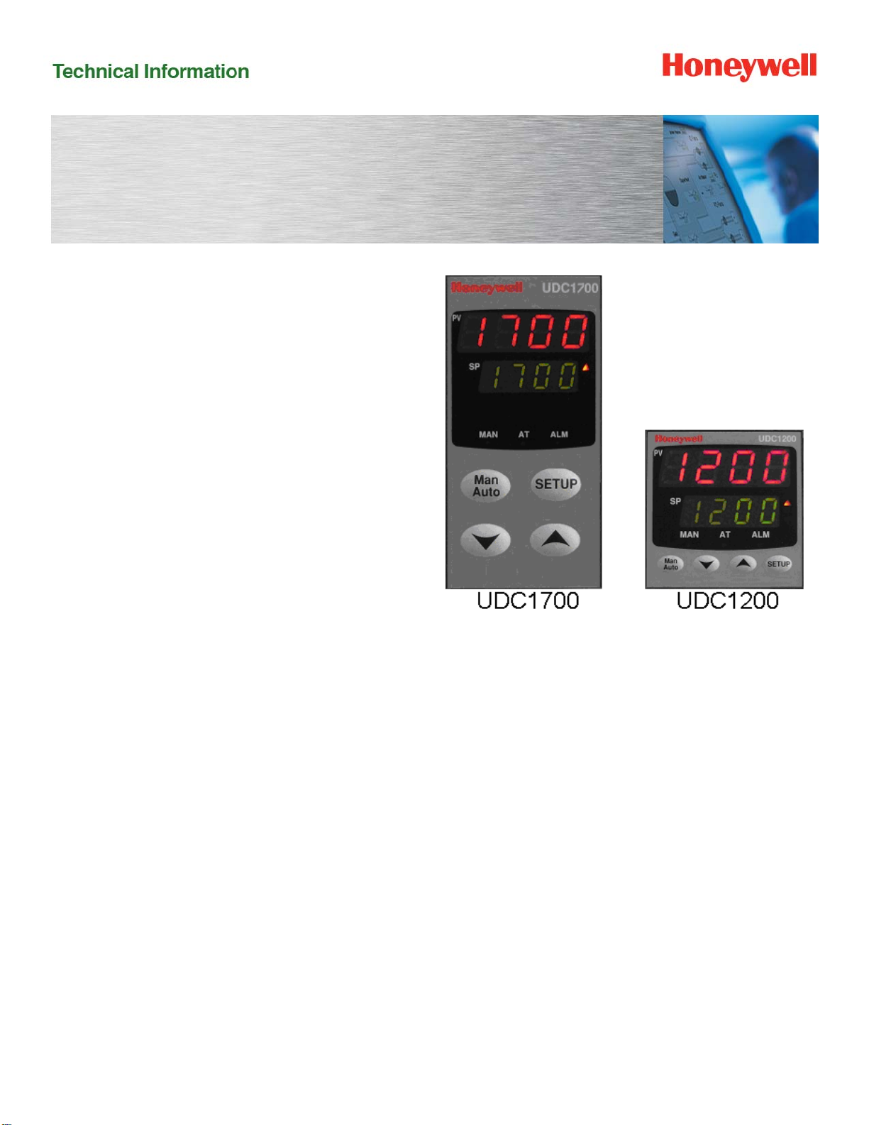
UDC1200 & UDC1700 Universal Digital Controllers
Series Micro-Pro
Specifications
51-52-03-35 June 2011
Overview
The UDC1200 & UDC1700 are microprocessor-based
1/16 DIN and 1/8 DIN controllers, which combine a
high degree of functionality and reliability at low cost.
They are fully dedicated to monitor and control
temperatures, pressures and levels in a wide range of
applications such as environmental chambers,
furnaces, ovens, packaging machines and other
applications in plastics and the food and beverage
industries. The large and easy-to-read dual 4-digit
display and tactile keypad make the UDC1200 and
UDC1700 easy to configure and use. Their
outstanding flexibility enables you to configure any unit
for any application and change it if required.
For the thousands of satisfied UDC1000/1500 users,
the UDC1200/ 1700 controllers are downward
compatible to existing UDC1000/1500 applications
and installations.
Features
Dual display
Two 4-digit displays with 7 LED segments, each
configurable for:
PV and SP (non adjustable)
PV and SP (adjustable)
PV and Ramping SP
PV only
Easier to configure
Two different configuration levels (Configuration mode
and set-up mode) provide easy access to parameters.
A 4-digit security code prevents unauthorized changes.
Moisture resistant front-face
Meets NEMA 3 / IP65 front-face protection against
dust and water.
Universal input
Accept seven different types of thermocouples, RTDs,
current and voltage linear inputs. All inputs are configurable
as standard.
Universal power supply
The UDC1200 and UDC1700 can operate on any line
voltage from 90 Vac to 264 Vac at 50/60 Hz. A 24/48 Vac/dc
model is available as an option.
Easy upgrade
All the option boards are jumper free and detected
automatically by the instrument.
Easy output selection
All the outputs (including the control output) of the
instrument can be changed to meet the exact
customer’s needs.
Page 2
UDC1200 & UDC1700 Universal Digital Controllers 2
p
Alarm strategy
Two soft alarms for PV, deviation high/low/absolute. A
special loop alarm is also provided to detect faults in
the control loop by continuously analyzing the PV
response to the control output. Alarm inhibit is
available on power up and setpoint switching.
Manual/Automatic mode
Manual control (via bumpless transfer) is enabled by
simply pressing the front-face AUTO/MAN key. The
“SET” LED flashes and the output power is displayed
on the lower display. Output can be adjusted with the
upper and lower keys.
Pre-tuning and self-tuning strategy
Pre-tuning is used to set up the PID parameters close
to the optimum values, which the self-tuning algorithm
uses to subsequently optimize the tuning parameters.
Limit controller
Packaged in 1/16 DIN, the UDC1200 limit controller is
designed to provide a safety shut-off and optional
alarm for use in a wide variety of applications.
Highly secure
A non-volatile memory based on EEPROM technology
ensures data integrity during loss of power supply, with
retention of more than 100 years. A 4-digit security code
prevents unauthorized or accidental change.
Upper display: 4 characters
dedicated to show the PV.
In configuration mode, it shows
the parameter value or selection
Lower display: 4 characters
dedicated in normal operation
mode to display the SP. In
configuration mode, it displays
the
arameter name.
Up to three outputs
The UDC1200 and UDC1700 provide up to three
outputs for time and current proportioning, duplex
mode (heat/cool), PV or SP retransmission, and
alarms.
Setpoint ramp
The current setpoint can ramp to a new-targeted
setpoint by way of a user defined ramp rate.
Dual setpoint
Dual setpoint option is available on the UDC1200 and
UDC1700. The current setpoint is selected by a digital
input. This option is exclusive with UDC1200 limit
model remote alarm reset.
Communication
An optional RS485 communications interface is
available on the UDC1200 and UDC1700. It provides a
link for up to 32 units and a host computer through
ASCII or Modbus RTU protocol at up to 19200 baud.
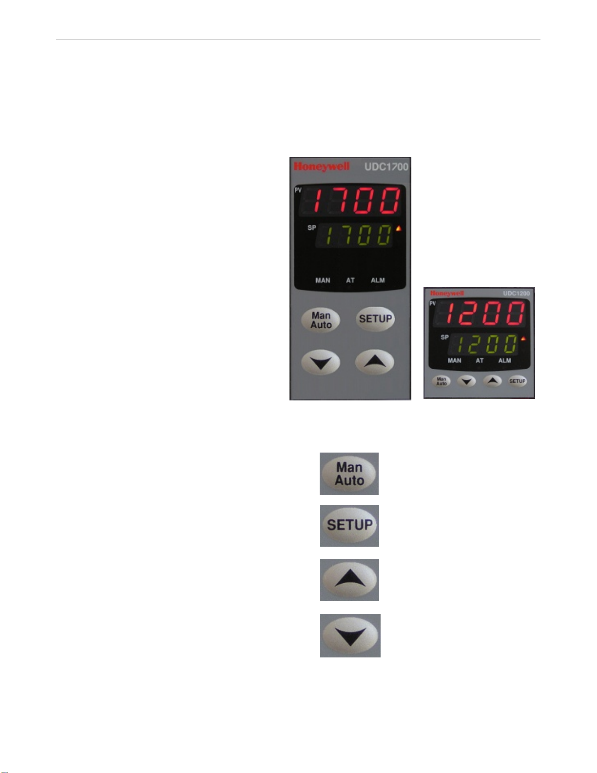
UDC1700 UDC1200
Selects manual or automatic mode. Becomes
« Reset » on UDC1200 Limit model.
Allows operator mode parameters to be scrolled.
In combination with the «Upper» key, allows
configuration mode or Setup mode to be entered.
Increases setpoint, output or configuration
parameter values.
Decreases setpoint, output or configuration
parameter values.
Page 3

UDC1200 & UDC1700 Universal Digital Controllers 3
Optional Features
The following can be selected via the Model selection
Guide (see page 8):
RS485 ASCII communication
RS485 Modbus RTU communication
Digital Input
Output 2
Output 3
Power Supply 24/48 Vac/dc
Physical Description
The UDC1200 controller is housed in a 110 mm (4.33
inches) deep case with a standard UDC gray bezel. It
can be mounted in a 1/16 DIN panel cutout.
The UDC1700 controller is housed in a 100 mm (3.94
inches) deep case and can be mounted in a 1/8 DIN
panel cutout. By using the pre-assembled mounting
fixture delivered with the unit, you can easily and
securely install the controller into the panel cutout.
Modular plug-in construction allows rapid access and
saves time. All inputs and outputs are connected on
the rear terminal block by screws.
Operator Interface
Four display combinations are offered to the operator.
The upper 4-digit 7-segment display is always
dedicated to monitor the PV. The lower display can
show:
SETPOINT (read only)
SETPOINT (adjustable)
RAMPING setpoint (ramp mode)
BLANK
Universal Inputs
All input types are available on any unit. Selection
among the various types of inputs is made by prompt
configuration. As soon as the Process Variable
reaches the value of the input range limit, the controller
displays a message. A sensor break indication is also
provided. A configurable digital filter is available from
0.5 seconds to 100.0 seconds.
Outputs
Three types of outputs (RELAY, SSR driver or DC linear)
are selectable for three outputs, through the model selection
guide or by adding a plug-in module for outputs 1, 2 and 3.
Outputs Algorithm
The UDC1200 and UDC1700 are available with the
following output algorithms:
Time proportional:
ON/OFF or time proportional with
electromechanical relay SPDT 2 A or SSR driver
(open collector).
Current proportional:
Supply directly proportional current or voltage
signal to the final control elements which require 020 mA, 4 20 mA, 0-10 V or 0-5 V.
Time proportional duplex:
Three duplex modes can be selected, either
ON/OFF duplex, time proportional duplex
(heat/cool with two proportional bands, two cycle
times and deadband) or TPSC.
Current proportional duplex:
In addition to the first current/voltage output, a
second similar output with its own proportional
band is provided.
Current/Time or Time/Current duplex:
Provides a variation of traditional time or current
duplex mode by mixing current and time
proportioning together.
Control Algorithms
Four control algorithms can be set up through the
configuration menu:
On/Off PID
PD + MR TPSC
The TPSC (Three Position Step Control) control algorithm is
dedicated to control valve positioning without slidewire
feedback from the motor shaft.
Page 4

UDC1200 & UDC1700 Universal Digital Controllers 4
Configuration
There are two levels of configuration. The SET-UP
mode allows modification of current parameters such
as tuning parameters, alarm values, setpoint limit,
ramp enable, auto-manual mode enable and autopretune enable.
The CONFIGURATION mode is more oriented to unit
personality: input selection, output 2 and 3 usage,
alarm type, communication address and lockout code.
The operator mode screens are only selectable via the
configuration software only. For instance, the alarm
value screen can be moved from setup mode to
normal operator mode if desired.
Control Mode
Manual or automatic mode with bumpless transfer is
standard feature. In manual mode, the operator can
directly control the output through the two front face
keys (raise and lower keys). The output value is
monitored on the lower display.
Alarms
Outputs 1, 2 and 3 can be used as alarms. Two
electromechanical single pole double throw relays can
activate external equipment when alarm setpoints are
reached. An LED is also activated on the front-face. A
direct or reverse acting alarm output can be
configured. A logical combination of the two alarms:
OR, AND or hysteresis (active when both alarms are
active and inactive when both alarms are inactive) can
be set which associates the two alarms status before
energizing the relay. In order to detect a defective
control loop, the controller can supply special loop
alarm control by continually monitoring the PV
response to output demand. A timer is automatically
set up when any output is on saturation mode. When
the timer reaches twice the reset time with no PV
response, the loop alarm is activated. With this soft
alarm there is no need for a heater circuit breaker,
saving wiring time and costs.
Limit Controller
The UDC1200 1/16 DIN limit controller provides a latched
relay output which is activated when the process parameters
either exceed or fall bellow the desired value, providing a
failsafe cut-off which has to be manually reset before the
process can continue.
The UDC1200 limit controller can be configured to be either
a “high limit” unit where the delay will de-energize when the
PV is above the limit setpoint, or a “low limit”, where the
relay will drop out when the PV falls below the setpoint.
A LED indicator shows when limits have been exceeded,
and when the relay is latched out.
The optional digital input allows a remote reset function.
Remote Setpoint Model
The UDC1700 1/8 DIN "R" model controller has a second
input available that accepts either a linear or potentiometer
input signal as a remote setpoint. The input signals
accepted are field-configurable and are: 0-5 V, 1-5 V, 0-10
V, 2-10 V, 0-20 mA, 4-20 mA (factory set), 0-50 mV, 10-50
mV, 0 100 mV, or 0-2000 ohms. This allows the controller
to act as a "slave" controller accepting a setpoint value from
a 'master' device such as a PLC or setpoint-programming
controller (such as the DCP50, DCP100, DCP300, or
DCP550 series).
The UDC1700R also includes a standard digital input
allowing remote switching between the local setpoint and
the remote setpoint value. Also standard in this model is
"fuzzy" autotune software that minimizes process variable
overshoot when responding to a setpoint change.
PC Software
The UDC1200 & 1700 are supported with PC software
allowing you to quickly configure your device using
configuration wizards, or to perform diagnostics.
Display
Dual, four-digit LED display with decimal point location
configurable up to three places for linear ranges only.
Page 5
UDC1200 & UDC1700 Universal Digital Controllers 5
Specifications (Applies to both UDC1200 and UDC1700)
Technical data
Accuracy 0.1 % of span 1 LSD
Temperature Stability 0.01 % of span per ºC
Input Signal Failure Fail-safe output value: Achieved when burnout is detected.
Input Impedance Voltage impedance: 47 Kohms
Input Sampling Rate Four samples per second
Input Filter Digital filter configurable from front panel
Input Resolution 14 bits approxi m ately, always four times better than display resolution
Input Isolation Universal input isolated at 2500 V from all outputs except SSR and from power supply
Stray Rejection Common mode rejection: > 120 dB at 50/60 Hz
Approvals UL recognized to US & Canadian standards
Control Output Type Type available:
Alarms Maximum number of alarms: 2 soft alarms setpoint + 1 loop alarm
Value depends on configuration.
For thermocouple and mV input detected by any lead break: Upscale burnout
For RTD: Burnout detected by any lead break
Current or voltage input: Burnout set by open circuit detection
Current input: 4.7 ohms
All others: 100 Mohms
0.0 (Off), from 0.5 seconds to 100.0 seconds in 0.5 seconds increment
Serial mode rejection: > 500% of span at 50/60 Hz
FM approval on the UDC1200 limit model
Product design to meet CE MARK requirement
Output 1/2/3: DC, Electromechanical relay, SSR drive (open collector)
DC linear output:
0-20 mA, 4-20 mA, 0-5 V, 0-10 V
Accuracy: 0.25 % (250 ohms for mA, 2 Kohms for voltage)
Resolution: 80 bits in 250 ms (10 bits in 1 second typical > 10 bits in > 1 second)
Load impedance: 500 ohms maximum for current output,
500 ohms minimum for voltage output
Isolation: Isolated 2500 V from all other inputs and outputs
Range selection method: Front panel code setting
Temperature stability: 0.01 % / °C
Electromechanical relay: SPDT contact
Resistive load: 2 A at 120 V or 240 V
Life time: > 500000 operations at rated voltage/current
SSR drive/TTL:
Drive capability: SSR > 10 Vdc into 250 ohms minimum
Isolation: Not isolated from input and other SSR output
Alarm inhibit available on power up and setpoint switching
Alarm output: Up to two relays or SSR output on outputs 2 and 3
Types: PV high or low, band, deviation high or low, loop
Combination alarms: Logical “OR”, “AND” or hysteresis of alarms availab le to
individual hardware output
Page 6

UDC1200 & UDC1700 Universal Digital Controllers 6
Loop Control Automatic tuning type: Pre-tune and self-tune
Proportional bands: 0 (inactive), 0.5 % to 999.9 % of input span with 0.1% increments.
Two proportional bands available for duplex mode
Reset: Off or from 1sec. to 99 min 59 sec.
Rate: From 0 sec. to 99 min 59 sec.
Manual reset: from 0 to 100 % of output (single output), from –100 % to 100 % of
output (dual output)
Deadband: 20 of PB1 + PB2
ON/OFF hysteresis: 0.1% to 10.0 % of input span
Auto/manual mode: Front key selectable with bumpless transfer between automatic
and manual mode
Cycle times: Up to two cycle times available for time duplex control
Selection: 0.5, 1, 2, 4, 8, 16, 32, 64, 128, 256, or 512 seconds
Setpoint ramp: From 1 to 9999 engineering units per hour
Retransmission Output Any output can be selected to retransmit the process value or setpoint as a linear
(current or voltage) output
Digital Input (optional) On contact the digital input will switch between SP1/SP2 or Auto/Manual or DC100L
Remote Reset
Communication Interface RS485 – ASCII or Modbus RTU (selectable from the menu)
Baud rate: 1200, 2400, 4800, 9600 or 19200 baud
Link characteristics: 32 drops maximum, ASCII or Modbus protocols, two wires
Mounting Plug-in with pre-assembled mounting fixture
Wiring Connection Screw terminals on the rear of the case (combination head)
Power Consumption 4 W
Physical (UDC1200) Weight: 210 grams maximum
Height: 48 mm / 1.89 in
Width: 48 mm / 1.89 in
Depth: 110 mm / 4.33 in
Cut out: 45 mm x 45 mm / 1.77 in x 1.77 in
Physical (UDC1700) Weight: 250 grams maximum
Height: 96 mm / 3.78 in
Width: 48 mm / 1.89 in
Depth: 100 mm / 3.94 in
Cut out: 45 mm x 92 mm / 1.77 in x 3.62 in
Environmental EMI Susceptibility: Designed to meet EN55101
EMI Emission: Designed to meet EN55022
Safety Considerations: Designed to comply with IEC1010-1as far as applicable
Front Panel Sealing NEMA 3 / IP66
Page 7

UDC1200 & UDC1700 Universal Digital Controllers 7
Input Actuations
Ranges
Thermocouple types °F °C
(Fixed decimal) R
S
J
J
T
T
K
K
L
L
B
C
N
RTD: (3 wires connection)
PT100 (IEC) = 0.00385
(Fixed decimal)
DC linear:
32 – 3198
32 – 3204
-328 – 2192
-199.9 – 999.9
-400 – 752
-199.9 – 752
-400 – 2503
-128.8 – 537.7
32 – 1403
32 – 999.9
211 – 3315
32 – 4208
32 – 2551
-328 – 1472
-199.9 – 999.9
10 – 50 mV
4 – 20 mA
1 – 5 V
2 – 10 V
0 – 1759
0 – 1762
-200 – 1200
-128.8 – 537.7
-250 – 400
-128.8 – 400
-240– 1373
-199.9 – 999.9
0 – 762
0 – 537.7
100 – 1824
0 – 2320
0 – 1399
-199 – 800
-128.8 – 537.7
0 – 50 mV
0 – 20 mA
0 – 5 V
0 – 10 V
Operating Conditions
Ambient Temperature 20 °C 2 °C
Relative Humidity 60-70 % 20-95 % non -condensing
Voltage 90-264 Vac 1 % 90-264 Vac
Frequency 50 Hz 50-60 Hz
Source Resistance < 10 ohms for
Lead resistance for RTD < 0.1 ohm/lead
Reference
Conditions
(68 °F 4 °F)
1000 ohms maximum for
thermocouple
50 ohms per lead maximum
(PT100)
Operative
Limits
0 °C to 55 °C
(32 °F to 131 °F)
thermocouple
balanced
Transportation and
Storage
–20 °C to 80 °C
(–4 °F to 176 °F)
Page 8

UDC1200 & UDC1700 Universal Digital Controllers 8
Sales and Service
For application assistance, current specifications, pricing, or name of the nearest Authorized Distributor, contact one of the offices below.
Asia Pacific Global
Technical Support
Field Instruments
Phone: +65 6580 3156
Fax: +65 6445-3033
Australia
Honeywell Limited
Phone: +(61) 7-3846 1255
FAX: +(61) 7-3840 6481
Toll Free 1300-36-39-36
Toll Free Fax:
1300-36-04-70
China – PRC - Beijing
Honeywell China Inc.
Phone: +(86-10) 84583280
Fax: +(86-10) 8458-4650
China – PRC - Shanghai
Honeywell China Inc.
Phone: (86-21) 5257-4568
Fax: (86-21) 6237-2826
China – PRC - Chengdu
Honeywell China Inc.
Phone: +(86-28) 66135078
Fax: +(86-28) 8678-7061
China – PRC - Xi’an
Honeywell China Ltd Xi’an.
Phone: +(86-29) 88337490
Fax: +(86-29) 8833-7489
China – PRC - Shenzhen-
Honeywell China Inc.
Phone: +(86) 755-25181226
Fax: +(86) 755-2518-1221
Indonesia
PT Honeywell Indonesia
Phone: +(62) 21-535-8833
FAX: +(62) 21-5367 1008
Honeywell Automation
India Ltd.
Honeywell Ltd.
Phone:+(91) 6603-9400
Fax: +(91) 6603-9600
Japan
Honeywell Inc.
Phone: +(81) 3 6730 7197
Fax: +(81) 3 6730 7228
Malaysia
Honeywell Engineering
Sdn Bhd
Phone: +(603) 7958-4788
Fax: +(603) 7958-8922
New Zealand
Honeywell Limited
Phone: +(64-9) 623-5050
Fax: +(64-9) 623-5060
Toll Free (0800) 202-088
Singapore
Honeywell Pte Ltd.
Phone: +(65) 6580 3278
Fax: +(65) 6445-3033
South Korea
Honeywell Korea Co Ltd
Phone: +(822) 799 6114
Fax: +(822) 792 9015
Thailand
Honeywell Systems
(Thailand) Ltd.
Phone: +(662) 693-3099
FAX: +(662) 693-3089
Taiwan R.O.C.
Honeywell Taiwan Ltd.
Phone: +(886-2) 22451000
FAX: +(886-2) 2245-3243
SE Asia Countries
see Honeywell Pte Ltd
(Singapore)
for: Philippines, Pakistan,
Cambodia, Guam, Laos,
Myanmar, Vietnam,
East Timor
SE Asia Countries
see Honeywell
Automation India Ltd for:
Bangladesh
Nepal
Sri Lanka
EUROPE
Austria
Honeywell Austria GmbH
Phone: +43 (316)400123
FAX: +43 (316)40017
Belgium
Honeywell SA/NV
Phone:+32 (0)2728 24 07
FAX: +32 (0)2728 22 45
Bulgaria
Honeywell EOOD
Phone: +(359) 2 40 20
900
FAX: +(359) 2 40 20 990
Czech Republic
Honeywell spol. s.r.o.
Phone:+420 242 442 232
FAX: +420 242 442 131
Denmark
Honeywell A/S
Phone: +(45) 39 55 55 55
FAX: +(45) 39 55 55 58
Finland
Honeywell OY
Phone: +358 (0)20752 2753
FAX: +358 (0) 20752 2751
France
Honeywell SA
Phone: +33 (0)1 60198075
FAX: +33 (0)1 60198201
Germany
Honeywell AG
Phone: +49 (69)8064-299
FAX: +49 (69)806497336
Hungary
Honeywell Kft.
Phone: +36-1-451 4300
FAX: +36-1-451 4343
Italy
Honeywell S.p.A.
Phone:+390292146307
FAX: +39 0292146377
The Netherlands
Honeywell B.V.
Phone: +31 (0) 20 5656200
FAX: +31 (0) 20 5656210
Norway
Honeywell A/S
Phone: (45) 39 55 55 55
Poland
Honeywell Sp. zo.o
Phone: +48-22-6060900
FAX: +48-22-6060901
Portugal
Honeywell Portugal Lda
Phone: +351 21 424 5000
FAX: +351 21 424 50 99
Romania
Honeywell Bucharest
Phone: +40 (0) 21 2316437
FAX: +40 (0) 21 2316439
Russian Federation (RF),
Honeywell Field Solutions
Kievskaya str., 7,
Moscow 121059, Russia
Phone +7 (495) 796 98 60
Fax +7 (495) 797 99 64
Slovak Republic
Honeywell s.r.o.
Phone: +421-2-58247 410
FAX: +421-2-58247 415
Spain
Honeywell S.A.
Phone: +34 (0)91313 61 00
FAX: +34 (0)91313 61 30
Sweden
Honeywell AB
Phone: +(46) 8 775 55 00
FAX: +(46) 8 775 56 00
Switzerland
Honeywell AG
Phone: +41 18552448
FAX: +(41) 1 855 24 45
Turkey
Honeywell Turkey A.S.
Phone: +90 216 578 71 00
FAX: +90 216 575 66 35
Ukraine
Honeywell
Tel: +380-44-201 44 74
Fax: +380-44-201-44-75
United Kingdom
Honeywell Control Systems
Ltd.
Phone: +44 (0)1344 655251
FAX: +44 (0) 1344 655554
MIDDLE EAST
Abu Dhabi U A E
Middle East Headquarters
Honeywell Middle East Ltd.
Phone: +971 2 4041246
FAX: +971 2 4432536
Sultanate of Oman
Honeywell & Co Oman LLC
Phone: +968 24 701153/
Ext.33
FAX +968 24 787351
Saudia Arabia
Honeywell Turki Arabia Ltd
Jubail Office
Phone: +966-3-341-0140
Fax: +966-3-341-0216
Honeywell - ATCO
Dammam Office
Phone: 0096638304584
Fax: 0096638338059
Kuwait
Honeywell Kuwait KSC
Phone: +965 242 1327 to 30
Fax: +965 242 8315
And
Phone: +965 326
2934/1821Fax: +965 326
1714
AFRICA
Mediterranean & African
Distributors
Honeywell SpA
Phone: +39 (02) 250 10 604
FAX: +39 (02) 250 10 659
South Africa (Republic of)
and sub saharan
Honeywell Southern Africa
Honeywell S.A. Pty. Ltd.
Phone: +27 11 6958000
FAX +27 118051504
NORTH AMERICA
Canada
Honeywell LTD
Phone: 1-800-737-3360
FAX: 1-800-565-4130
USA
Honeywell Process
Solutions,
Phone: 1-800-423-9883
Or 1-800-343-0228
Email: ask-
ssc@honeywell.com
SOUTH AMERICA
Argentina
Honeywell S.A.I.C.
Phone: +(54-11) 4383-3637
FAX: +(54-11) 4325-6470
Brazil
Honeywell do Brasil & Cia
Phone: +(55-11) 7266-1900
FAX: +(55-11) 7266-1905
Chile
Honeywell Chile, S.A.
Phone: +(56-2) 233-0688
FAX: +(56-2) 231-6679
Mexico
Honeywell S.A. de C.V.
Phone: +(52) 55 5259-1966
FAX: +(52) 55 5570-2985
Puerto Rico
Honeywell Inc.
Phone: +(809) 792-7075
FAX: +(809) 792-0053
Trinidad
Honeywell Inc.
Phone: +(868) 624-3964
FAX: +(868) 624-3969
Venezuela
Honeywell CA
Phone: +(58-2) 238-0211
FAX: +(58-2) 238-3391
Page 9

UDC1200 & UDC1700 Universal Digital Controllers 9
r
R
Model Selection Guides are subject to change and are inserted into the specifications as guidance only.
Prior to specifying or ordering a model check for the latest revision Model Selection Guide s which are published at:
http://hpsweb.honeywell.com/Cultures/en-US/Products/Instrumentation/ProductModelSelectionGuides/default.htm
Model Selection Guide
51-51-16U-78
Issue 13
Page 1 of 3
UDC1200 MICRO-PRO
Model Selection Guide
Un iver sa l Digital Con trolle
Instructions
Select the desired key number. T he ar r ow to the right marks the selections available.
M ak e one select ion eac h from Tables I through VI II using the column below the proper arr ow.
Key N umber I II III IV V VI VIIVIII
DC _ _ _ _ -_-_-_-_-_-_-_-_
KEY NUMBE
1/16 DI N Controller: RTD or Linear mV
48x4 8mm Thermocouple
Input Type
(Field Selec table) Linear Voltage
TABLE I
Output 1
Description
Linear mA
Limit Controller - FM Approv ed
TPS C Controller (Ther mocouple F ac tory S et)
Relay 1
SSR Dr iver 2
Linear: 0 - 10 Volts 3
Linear: 0 - 20 mA 4
Linear: 0 - 5 Volts 5
Linear: 4- 20mA 7
Selection Availability
DC1201
DC1202
DC1203
DC1204
DC120L
DC120T
TABLE II
Output 2
TABLE III
Output 3
TABLE IV
Communications No Selection 0
None 0
Relay 1
SSR Dr iver 2
Linear: 0 - 10 Volts 3
Linear: 0 - 20 ma 4
Linear: 0 - 5 Volts 5
Linear: 4- 20mA 7
Dual Relay B oar d 9
None 0
Relay 1
SSR Dr iver 2
Linear: 4- 20mA 7
Transmitter P ower S upply (24Vdc) 8
RS485 ASCII S er ial Communication 1
Digital Input (SP1/SP2 Selection or Auto/Manual 2
Select ion or DC100L Remote Reset)
RS485 MODBUS Communication 3
Basic Remote Setpoint 4
Page 10

UDC1200 & UDC1700 Universal Digital Controllers 10
Availability
DC120_
TABLE V
Power Supply Power Supply 90 to 264 Vac 1
Power S upply 24 to 48 Vac/dc 2
TABLE VI
Manuals English (51-52-25-123)
(Single sheet Frenc h (51-52-25-123- FR) 1
Concise manuals German (51-52-25-123-GE) 2
for UDC1200) It alian (51-52-25- 123- IT) 3
Spanish (51-52-25-123-SP) 4
TABLE VII
Packaging Individual Carton 0
Bulk P ac k of 10 identical models 1
Bulk P ac k of 50 identical models 2
Bulk Pac k of 100 identical models 3
TABLE VIII
Specials
UDC1200 sty l e overlay 0
Special Instrument (Consult Factory) S
UDC1200 MICRO-PRO
Universal Digital Controller
Selection 1 2 3 4 L T
Supplemental
Accessori es & Kits
0
Des cr ip tion
Option Slot 1
Relay module 51453391-501
10 Vdc SSR Driver module 51453391-502
Linear (mA/V d c ) module 51453391-504
Option Slot 2 & 3
Relay module 51453391-506
10 Vdc SSR Driver module 51453391-507
Linear (mA/V d c ) module 51453391-509
Dual Relay B oard ( S lot 2 only) 51453391-510
24V dc t r ansmitter module (Slot 3 only) 51453391-511
Option Slot A
RS485 communication module 51453391-512
Digital Input module 51453391-513
Basic Remote Set p oint module 51453391- 515
Others
PC Software (inc ludes th e c able) 51453391-514
Produc t Manual ( 8 1/2 x 11) English 51-52-25-122
French 51-52-25-122-FR
UDC1000/1200 Fixing str ap 46189016-501
UDC1500/1700 Fixing str ap 46189017-501
UDC1000/1200 Rep lac ement c ase 46189018-501
UDC1500/1700 Rep lac ement c ase 46189019-501
DIN Rail Adaptor Kit 46189025-501
Part Number
Page 11

UDC1200 & UDC1700 Universal Digital Controllers 11
s
V
_
_-_-_-_-_-_-_-_
Model Selection Guides are subject to change and are inserted into the specifications as guidance only.
Prior to specifying or ordering a model check for the latest revision Model Selection Guide s which are published at:
http://hpsweb.honeywell.com/Cultures/en-US/Products/Instrumentation/ProductModelSelectionGuides/default.htm
Model Selection Guide
51-51-16U-85
Issue 8
Page 1 of 3
UDC1700 MICRO-PRO
Model Selection Guide
Un i versal D igital Controller
Instruction
Select the desired key number. The ar r ow t o the right marks the selections available.
M ak e one select ion eac h from Tables I through VII I using the column below the pr oper ar r ow.
Key Number I II III IV V VI VII
_ _ _ _ _ -
KEY NUMBER Selection Availability
1/8 DIN Controller:
48x96mm RTD or Linear mV DC1701
Input Type
(Field S elec table) Linear mA DC1703
TABLE I
Output 1
Description
Thermocouple DC1702
Linear Voltage DC1704
TP S C Controller * DC170T
Remote Set poin t, Fuzz y Logic, Digital Input * DC170R
* fac tory set for thermocouple input
Relay 1
SSR Dr iver 2
Linear 0 t o 10 Volts 3
Linear 0 to 20 ma 4
Linear 0 to 5 Volts 5
Linear 4 to 20 mA 7
III
TABLE II
Output 2
TABLE III
Output 3
None 0
Relay 1
SSR Dr iver 2
Linear 0 t o 10 Volts 3
Linear 0 to 20 ma 4
Linear 0 to 5 Volts 5
Linear 4 to 20 mA 7
Dual Relay Board 9
None 0
Relay 1
SSR Dr iver 2
Linear 0 t o 10 Volts 3
Linear 0 to 20 ma 4
Linear 0 to 5 Volts 5
Linear 4 to 20 mA 7
Tr ansmitter P ower S upply (24Vdc) 8
Dual Relay Board 9
Page 12

UDC1200 & UDC1700 Universal Digital Controllers 12
Model Selection Guide (continued)
DC170 _ Availability
TABLE IV
Selection 1 2 3 4 T R
No Selec tion 0
Option 1 RS485 ASCII Serial Communication 1
Digital Input (SP1/SP2 Selection) 2
RS485 MODB US Communication 3
Basic Remote Setpoint 4
TABLE V
Option 2 Power S upply 90 t o 264 Vac 1
Power S uppl y 24 to 48 Vac/ dc 2
TABLE VI
Manuals English (51-52-25-123) 0
(Singl e sheet Frenc h (51-52- 25- 123- FR) 1
Concise manuals Ger man (51-52-25-123- GE) 2
for UDC1200) Italian (51-52-25-123- IT) 3
Spanish (51-52-25-123-SP) 4
TABLE VII
Pack agi ng I ndividual Carton 0
Bulk Pack of 10 identical models 1
Bulk Pack of 50 identical models 2
TABLE VIII
Special None 0
Special I nstrument (Consult F ac t or y) S
Page 13

UDC1200 & UDC1700 Universal Digital Controllers 13
t
UDC1700 MICRO-PRO
Universal Digital Controller
Descr iption
Option Slot 1
Relay module 51453391-501
10 Vdc SSR Dr iver module 51453391-502
Linear (mA/Vdc) module 51453391-504
Option Slot 2 & 3
Relay module 51453391-506
10 Vdc SSR Dr iver module 51453391-507
Linear (mA/Vdc) module 51453391-509
Dual Relay B oar d 51453391-510
24V dc transmitt er module (Slot 3 only) 51453391-511
Option Slot A
RS485 communication module 51453391-512
Digita l I n put module 51453391-513
Basic Remote Se tpoint module 51453391-515
Supplemental
Accessories & Ki t s
Part Num ber
Option Slot B
Full r e mote Setpoint module (to upgrade a DC1700 t o a DC17 0R) 51 453391-516
Others
PC Software ( i nc ludes t he c a ble) 51453391-514
Produc t M anual ( 8 1/2 x 11) English 51-52- 25- 122
French 51-52-25-122-FR
UDC1000/ 1200 Fix ing str ap 46189016-501
UDC1500/ 1700 Fix ing str ap 46189017-501
UDC1000/ 1200 R eplac ement c ase 46189018-501
UDC1500/ 1700 R eplac ement c ase 46189019-501
DIN Rail Adaptor K i
46189025-501
Page 14

UDC1200 & UDC1700 Universal Digital Controllers 14
Warranty/Remedy
Honeywell warrants goods of its manufacture as being free of defective materials and faulty workmanship. Contact your local
sales office for warranty information. If warranted goods are returned to Honeywell during the peri od of coverage, Honeywell
will repair or replace without charge those items it finds defective. The foregoing is Buyer's sole remedy and is in lieu of all
other warranties, expressed or implied, including those of merchantability and fitness for a particular purpose.
Specifications may change without notice. The information we supply is believed to be accurate and reliable as of this
printing. However, we assume no responsibility for its use.
While we provide application assistance personally, throug h our literature and the Honeywell web site, it is up to the
customer to determine the suitability of the product in the application.
Specifications are subject to change without notice.
For More Information
Learn more about how Honeywell’s UDC1200/1700
Micro-Pro Series can monitor and control
temperatures, pressures and levels in a wide
range of applications visit our website
www.honeywell.com/ps/hfs
or contact your
Honeywell account manager.
Honeywell Process Solutions
1860 W. Rose Garden Lane
Phoenix, Arizona 85027
Tel: 1-800-423-9883 or 1-800-343-0228
www.honeywell.com/ps
51-52-03-35
June 2011
© 2011 Honeywell International Inc.
 Loading...