

Page 1

UDA2182
Universal Dual Analyzer
Product Manual
70-82-25-119
January 2009
Honeywell Process Solutions
Page 2

WARRANTY/REMEDY
Honeywell warrants goods of its manufacture as being free of defective materials and faulty
workmanship. Contact your local sales office for warranty information. If warranted goods are
returned to Honeywell during the period of coverage, Honeywell will repair or replace without charge
those items it finds defective. The foregoing is Buyer's sole remedy and is in lieu of all other
warranties, expressed or implied, including those of merchantability and fitness for a particular
purpose. Specifications may change without notice. The information we supply is believed to be
accurate and reliable as of this printing. However, we assume no responsibility for its use.
While we provide application assistance personally, through our literature and the Honeywell web
site, it is up to the customer to determine the suitability of the product in the application.
Notices and Trademarks
Copyright 2008 by Honeywell
Revision 5 January 2009
Honeywell Process Solutions
Honeywell
2500 W. Union Hill Drive
Phoenix, Arizona 85027
UDA2182 is a U.S. registered trademark of Honeywell
Other brand or product names are trademarks of their respective owners.
ii UDA2182 Universal Dual Analyzer Product Manual January 2009
Page 3

About This Document
Abstract
This document provides descriptions and procedures for the Installation, Configuration, Operation, and Troubleshooting of
your UDA2182 Universal Dual Analyzer.
Contacts
World Wide Web
The following lists Honeywell’s World Wide Web sites that will be of interest to our customers.
Honeywell Organization WWW Address (URL)
Corporate http://www.honeywell.com
Honeywell Field Solutions http://www.honeywell.com/ps
Technical tips http://content.honeywell.com/ipc/faq
Telephone
Contact us by telephone at the numbers listed below.
United States and Canada Honeywell 1-800-423-9883 Tech. Support
Organization Phone Number
1-800-525-7439 Service
January 2009 UDA2182 Universal Dual Analyzer Product Manual iii
Page 4
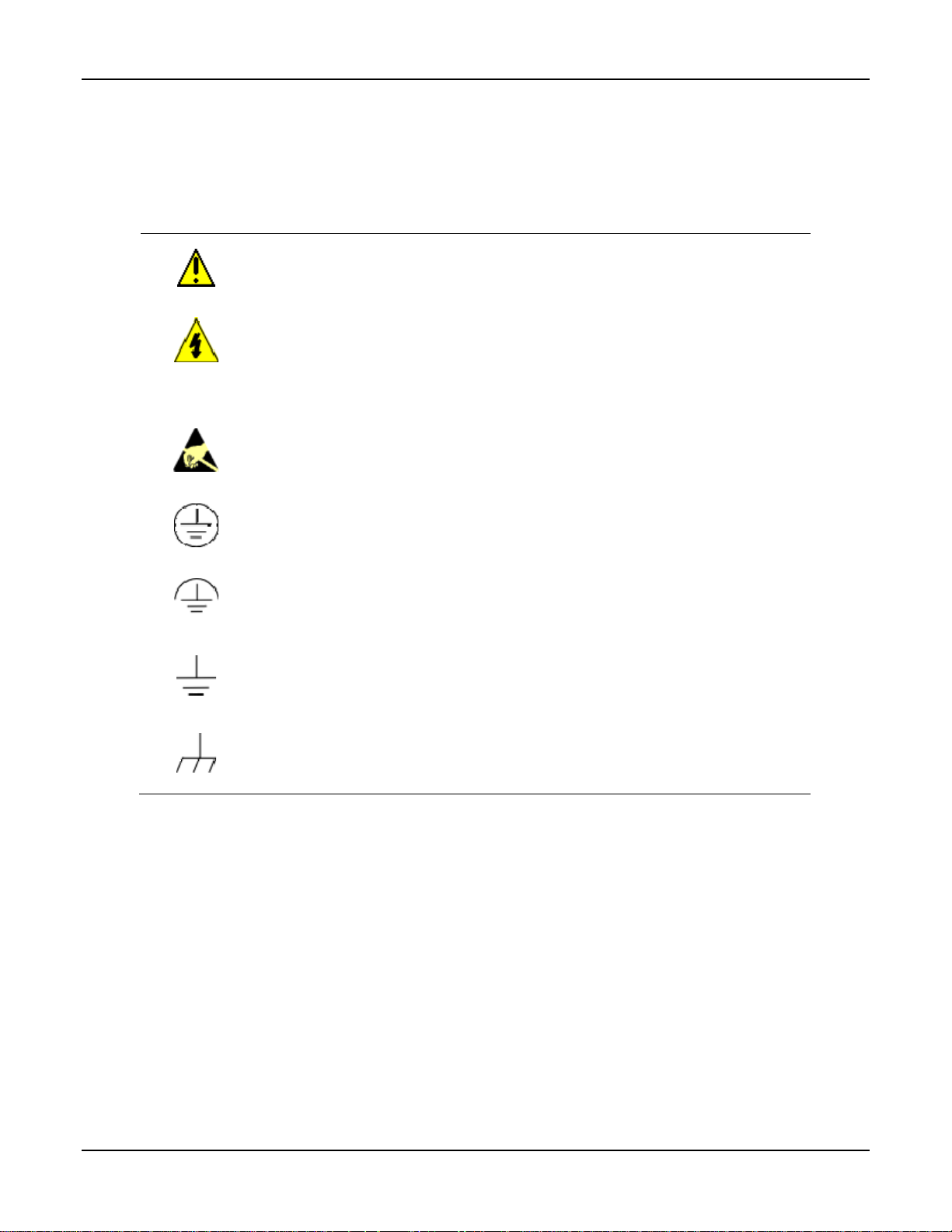
Symbol Definitions
The following table lists those symbols used in this document to denote certain conditions.
Symbol Definition
This CAUTION symbol on the equipment refers you to the Product Manual for
additional information. This symbol appears next to required information in the manual.
WARNING
PERSONAL INJURY: Risk of electrical shock. This symbol warns you of a potential
shock hazard where HAZARDOUS LIVE voltages greater than 30 Vrms, 42.4 Vpeak,
or 60 VDC may be accessible. Failure to comply with these instructions could result in
death or serious injury.
ATTENTION, Electrostatic Discharge (ESD) hazards. Observe precautions for
handling electrostatic sensitive devices
Protective Earth (PE) terminal. Provided for connection of the protective earth (green
or green/yellow) supply system conductor.
Functional earth terminal. Used for non-safety purposes such as noise immunity
improvement. NOTE: This connection shall be bonded to protective earth at the source
of supply in accordance with national local electrical code requirements.
Earth Ground. Functional earth connection. NOTE: This connection shall be bonded to
Protective earth at the source of supply in accordance with national and local electrical
code requirements.
Chassis Ground. Identifies a connection to the chassis or frame of the equipment shall
be bonded to Protective Earth at the source of supply in accordance with national and
local electrical code requirements.
iv UDA2182 Universal Dual Analyzer Product Manual January 2009
Page 5

Contents
1 INTRODUCTION ...................................................................................................1
1.1 Overview.........................................................................................................................................1
1.2 Features...........................................................................................................................................3
2 SPECIFICATIONS.................................................................................................5
2.1 Specifications..................................................................................................................................5
2.2 CE Conformity (Europe).................................................................................................................7
3 UNPACKING, PREPARATION, AND MOUNTING...............................................9
3.1 Overview.........................................................................................................................................9
3.2 Unpacking and Preparing..............................................................................................................10
3.3 Mounting.......................................................................................................................................10
4 POWER WIRING.................................................................................................15
4.1 Overview.......................................................................................................................................15
4.2 General Wiring Practices..............................................................................................................16
4.3 Power Wiring Considerations.......................................................................................................17
4.4 Installing Power Wiring................................................................................................................17
5 OPERATING THE ANALYZER...........................................................................20
5.1 Overview.......................................................................................................................................20
5.2 Analyzer Overview.......................................................................................................................21
5.3 Key Navigation.............................................................................................................................22
5.4 Displays Overview........................................................................................................................23
5.5 Input Displays...............................................................................................................................25
5.6 PID Displays.................................................................................................................................26
5.7 Auto Cycle Displays .....................................................................................................................28
5.7.1 Overview............................................................................................................................ 28
5.7.2 Access to Auto Cycle Displays..........................................................................................28
5.7.3 How it works......................................................................................................................29
5.7.4 Displays..............................................................................................................................29
5.7.5 Hold Active........................................................................................................................30
5.7.6 Probe Transit......................................................................................................................30
5.7.7 Cycle Start Src ...................................................................................................................30
5.7.8 Cycle Interval.....................................................................................................................30
5.7.9 Rinse Cycle Cnt .................................................................................................................30
5.7.10 Rinse Mins......................................................................................................................30
5.7.11 Resume Dly Mins...........................................................................................................30
3/08 UDA2182 Universal Dual Analyzer Product Manual v
Page 6

5.7.12 Manual Starting/Stopping the Auto Cycle .....................................................................31
5.7.13 Auto Cycle Fail ..............................................................................................................32
5.7.14 Conditional Sequencer Steps..........................................................................................32
5.8 Pharma Display............................................................................................................................. 33
5.8.1 Overview............................................................................................................................ 33
5.8.2 How it works......................................................................................................................33
5.8.3 Access to Pharma Display..................................................................................................34
5.8.4 Displays..............................................................................................................................34
5.8.5 Pharma Warning and Fail Signal .......................................................................................36
5.9 Cation Calc Display......................................................................................................................37
5.9.1 Overview............................................................................................................................ 37
5.9.2 How it works......................................................................................................................37
5.9.3 pH Calculation from Specific and Cation Conductivity Setup..........................................38
5.9.4 Calibration..........................................................................................................................39
5.9.5 CO2 by Degassed Conductivity..........................................................................................39
5.9.6 Access to Cation Display...................................................................................................39
5.9.7 Troubleshooting.................................................................................................................40
5.10 Status Display............................................................................................................................41
5.11 Event History.............................................................................................................................46
5.12 Process Instrument Explorer Software......................................................................................48
5.13 Modbus Communications..........................................................................................................50
6 CONFIGURATION...............................................................................................51
6.1 Overview.......................................................................................................................................51
6.2 UDA2182 Block Diagram ............................................................................................................52
6.3 Main Setup Menu..........................................................................................................................53
6.4 Basic Configuration Procedure.....................................................................................................55
6.4.1 General Rules for Editing...................................................................................................55
6.5 Analog and Digital Signal Sources...............................................................................................58
6.6 Inputs Configuration.....................................................................................................................63
6.7 Outputs Configuration ..................................................................................................................74
6.8 Relays Configuration....................................................................................................................76
6.9 Alarms Configuration ...................................................................................................................81
6.10 Monitors Configuration.............................................................................................................83
6.11 Math Configuration...................................................................................................................85
6.12 Logic Configuration..................................................................................................................87
6.13 Auxiliary Configuration............................................................................................................89
6.14 PID Control Configuration........................................................................................................92
6.15 Auto Cycling Configuration....................................................................................................100
6.15.1 Overview ......................................................................................................................100
6.15.2 Accessing Auto Cycle Menu........................................................................................100
6.15.3 Auto Cycling Configuration.........................................................................................101
6.15.4 pH Auto Cycling Configuration Example....................................................................103
vi UDA2182 Universal Dual Analyzer Product Manual January 2009
Page 7

6.16 Variables Configuration..........................................................................................................105
6.17 Communication Configuration................................................................................................106
6.18 Maintenance Configuration.....................................................................................................108
7 INPUTS AND OUTPUTS WIRING.....................................................................114
7.1 Overview.....................................................................................................................................114
7.2 General Wiring Practices............................................................................................................115
7.3 Inputs and Outputs......................................................................................................................117
7.4 Direct pH/ORP Input Wiring Diagrams......................................................................................120
7.5 pH Input from External Preamplifier/Cap Adapter Wiring Diagrams........................................126
7.6 Conductivity................................................................................................................................130
7.7 Dissolved Oxygen.......................................................................................................................131
7.8 Communications Card.................................................................................................................133
7.9 Outputs........................................................................................................................................134
7.10 Option Card.............................................................................................................................135
8 INPUT CALIBRATION.......................................................................................136
8.1 Overview.....................................................................................................................................136
8.2 Calibration Menu........................................................................................................................137
8.3 pH/ORP and Conductivity Overview .........................................................................................138
8.4 Recommendations for Successful Measurement and Calibration...............................................139
8.5 pH Calibration.............................................................................................................................140
8.5.1 Introduction......................................................................................................................140
8.5.2 Calibrating pH Electrodes Using Automatic Buffer recognition.....................................141
8.5.3 Buffering Method of Calibrating pH Electrodes..............................................................145
8.5.4 Sample Method of Calibrating pH Electrodes ................................................................. 148
8.5.5 Viewing and resetting pH Offset and (Standardization) pH Slope..................................150
8.6 ORP Calibration..........................................................................................................................151
8.6.1 Introduction......................................................................................................................151
8.6.2 ORP Calibration Using Reference Solution.....................................................................151
8.6.3 ORP Calibration Using Voltage Input .............................................................................154
8.6.4 Viewing and Resetting ORP Offset .................................................................................156
8.7 Conductivity Calibration.............................................................................................................157
8.7.1 Introduction......................................................................................................................157
8.7.2 Entering the Cal Factor for each cell................................................................................157
8.7.3 Determining and Entering the TDS Conversion Factor...................................................157
8.7.4 Determining TDS conversion factor................................................................................158
8.7.5 Performing Calibration Trim............................................................................................159
8.7.6 Resetting Calibration Trim...............................................................................................162
8.7.7 Cation pH Calibration......................................................................................................163
8.7.8 Resetting pH Offset..........................................................................................................165
8.8 Dissolved Oxygen Calibration....................................................................................................166
3/08 UDA2182 Universal Dual Analyzer Product Manual vii
Page 8

9 OUTPUTS CALIBRATION................................................................................178
9.1 Overview.....................................................................................................................................178
9.2 Output Calibration ......................................................................................................................179
10 TEMPERATURE INPUT CALIBRATION ..........................................................185
10.1 Overview.................................................................................................................................185
10.2 Temperature Input Calibration................................................................................................186
11 CALIBRATION HISTORY .................................................................................189
11.1 Overview.................................................................................................................................189
11.2 Clear Calibration History ........................................................................................................190
12 DIAGNOSTICS AND MESSAGES....................................................................191
12.1 Overview.................................................................................................................................191
12.2 System Status Messages..........................................................................................................192
12.3 Calibration Diagnostics...........................................................................................................193
12.4 Auto Cycle Fail Messages.......................................................................................................194
12.5 Pharma Fail Messages.............................................................................................................195
13 ETHERNET AND COMMUNICATIONS ............................................................196
13.1 Overview.................................................................................................................................196
14 ACCESSORIES AND REPLACEMENT PARTS LIST......................................197
14.1 Overview.................................................................................................................................197
14.2 Part Numbers...........................................................................................................................198
15 APPENDICES....................................................................................................199
15.1 Table of Contents ....................................................................................................................199
15.2 Appendix A – Entering Values for Lead Resistance Compensation.......................................200
15.3 Appendix B – Entering Values for Lead Resistance Compensation [Titanium Cells]............202
15.4 Appendix C - Cyanide Waste Treatment.................................................................................204
15.5 Appendix D – Chrome Waste Treatment................................................................................208
15.6 Appendix E – Two-cell Applications......................................................................................212
15.7 Appendix F – Using a Precision Check Resistor (For Conductivity) ....................................216
15.8 Appendix G – Noise Testing, Dissolved Oxygen Application................................................218
15.9 Appendix H – DO Probe and Analyzer Tests .........................................................................219
15.10 Appendix I – Parameters Affecting Dissolved Oxygen Measurement................................222
15.11 Appendix J – Discussion on Chemical Interferences on Measured DO Currents ...............223
15.12 Appendix K – Percent Saturation Readout..........................................................................225
viii UDA2182 Universal Dual Analyzer Product Manual January 2009
Page 9

15.13 Appendix L – Leak Detection in PPB Applications............................................................226
15.14 Appendix M – Procedure for Low Level ppb Dissolved Oxygen Testing ..........................227
15.15 Appendix N – Sample Tap Electrode Mounting Recommendations...................................229
15.16 Appendix O – Auto Clean and Auto Cal Examples ............................................................231
15.17 Appendix P – AutoClean and AutoCal Theory and Piping.................................................234
15.17.1 AutoCal Sequence and Piping......................................................................................235
INDEX..........................................................................................................................239
3/08 UDA2182 Universal Dual Analyzer Product Manual ix
Page 10

Tables
Table 3-1 Procedure for Unpacking and Preparing the UDA2182 ______________________________ 10
Table 3-2 Panel Mounting Procedure ____________________________________________________ 11
Table 4-1 Procedure for installing AC Power Wiring________________________________________ 17
Table 5-1 Function of Keys____________________________________________________________ 22
Table 5-2 Display Details Functions_____________________________________________________ 24
Table 5-3 Changing PID Parameters on the Display_________________________________________ 27
Table 5-4 Manually Starting/Stopping the Auto Cycle_______________________________________ 31
Table 5-5 Conditional Sequencer Steps for Auto Cycle ______________________________________ 32
Table 5-6 Selecting the Pharma Test on Display ___________________________________________ 35
Table 5-7 Status Display Details________________________________________________________ 41
Table 6-1 Basic Configuration Procedure_________________________________________________ 56
Table 6-2 Signal Sources______________________________________________________________ 58
Table 6-3 Analog Signal Sources _______________________________________________________ 59
Table 6-4 Digital Signal Sources________________________________________________________ 60
Table 6-5 Input Configuration__________________________________________________________ 63
Table 6-6 Outputs Configuration________________________________________________________ 74
Table 6-7 Relays Configuration ________________________________________________________ 77
Table 6-8 Alarms Configuration ________________________________________________________ 82
Table 6-9 Monitors Configuration_______________________________________________________ 83
Table 6-10 Math Configuration_________________________________________________________ 86
Table 6-11 Logic Configuration ________________________________________________________ 88
Table 6-12 Auxiliary Configuration _____________________________________________________ 90
Table 6-13 PID Configuration __________________________________________________________ 94
Table 6-14 PID Tuning _______________________________________________________________ 97
Table 6-15 PID Alarms _______________________________________________________________ 98
Table 6-16 Auto Cycling Configuration _________________________________________________ 101
Table 6-17 Example Auto Cycling Configuration for pH____________________________________ 103
Table 6-18 Variables Configuration ____________________________________________________ 105
Table 6-19 Communication Configuration _______________________________________________ 106
Table 6-20 Maintenance Configuration__________________________________________________ 108
Table 7-1 Recommended Maximum Wire Size ___________________________________________ 116
Table 7-2 Procedure for installing Input and Output wiring__________________________________ 119
Table 8-1 Standard pH Buffer Values___________________________________________________ 142
Table 8-2 Calibrating pH Electrodes Using Automatic Buffer Recognition______________________ 143
Table 8-3 Procedure for Buffering Method of Calibrating pH Electrodes _______________________ 146
Table 8-4 Procedure for Sample Method of Calibrating pH Electrodes _________________________ 148
Table 8-5 Oxidation-Reduction Potential of Reference Solutions at Specified Temperature________ 152
Table 8-6 Procedure for Calibrating ORP System Using a Reference Solution ___________________ 152
Table 8-7 Procedure for Calibrating ORP Analyzer Using Voltage Input _______________________ 154
Table 8-8 Conductivity of Potassium Chloride Solutions at 25 °C_____________________________ 160
Table 8-9 Procedure for Performing Calibration Trim Using a Reference Solution________________ 160
Table 8-10 Procedure for Sample Method of Calibrating Cation pH ___________________________ 163
Table 8-11 Calibrating a Dissolved Oxygen Probe Using Air Calibration Method ________________ 167
Table 8-12 Calibrating a Dissolved Oxygen Probe Using Sample Calibration Method_____________ 169
Table 8-13 Calibrating the Integral Pressure Sensor________________________________________ 171
Table 8-14 Running a Probe Bias Scan__________________________________________________ 174
Table 9-1 Procedure for Calibrating Analyzer Outputs______________________________________ 181
Table 10-1 Procedure for Calibrating the Temperature Inputs ________________________________ 186
x UDA2182 Universal Dual Analyzer Product Manual January 2009
Page 11

Table 11-1 Cal History items _________________________________________________________ 189
Table 12-1 Status Messages __________________________________________________________ 192
Table 12-2 Probe Calibration Diagnostics________________________________________________ 193
Table 12-3 Auto Cycle Fail Messages___________________________________________________ 194
Table 12-4 Pharma Fail Messages______________________________________________________ 195
Table 14-1 Part Numbers_____________________________________________________________ 198
Table 15-1 Data for Concentration Range Measurements ___________________________________ 217
Table 15-2 Dissolved Oxygen Solubility vs. Temperature ___________________________________ 225
Figures
Figure 3-1 Panel Mounting Dimensions (not to scale) _______________________________________ 11
Figure 3-2 Rear Panel Support Plate Dimensions___________________________________________ 12
Figure 3-3 Pipe Mounting Dimensions (not to scale) ________________________________________ 13
Figure 3-4 Wall Mounting Dimensions (not to scale)________________________________________ 14
Figure 4-1 Power Wiring______________________________________________________________ 19
Figure 5-1 UDA2182 Operator Interface (all display items shown)_____________________________ 21
Figure 5-2 Example – Two Input Display_________________________________________________ 25
Figure 5-3 PID Loop 1 Edit Display screen example ________________________________________ 26
Figure 5-4 Auto Cycle Display screen example ____________________________________________ 28
Figure 5-5 Pharma Display screen example _______________________________________________ 34
Figure 5-6 UDA for Cation and Degassed CO2_____________________________________________ 37
Figure 5-7 Cation Display screen example for pH calculations ________________________________ 39
Figure 5-8 Status Display screen example ________________________________________________ 41
Figure 5-9 Event History Display screen example __________________________________________ 46
Figure 5-10 Alarm Event Display screen example (Read Only)________________________________ 46
Figure 5-11 Screen capture of Process Instrument Explorer running on a Pocket PC_______________ 48
Figure 6-1 UDA2182 Block Diagram____________________________________________________ 52
Figure 7-1 Wiring Terminals and board Location__________________________________________ 118
Figure 7-2 Terminal Designations for Durafet III Electrode__________________________________ 120
Figure 7-3 Terminal Designations for Durafet II Electrode __________________________________ 121
Figure 7-4 Terminal Designations for Meredian II Electrode_________________________________ 122
Figure 7-5 Terminal Designations for Meredian II Electrode with Quick Disconnect______________ 122
Figure 7-6 Terminal Designations for ORP ______________________________________________ 123
Figure 7-7 Terminal Designations for Direct pH/ORP with Quick Disconnect Option_____________ 123
Figure 7-8 Terminal Designations for HPW7000 System____________________________________ 124
Figure 7-9 Terminal Designations for HB Series pH or ORP_________________________________ 125
Figure 7-10 Terminal Designations for Meredian Electrode with External Preamplifier____________ 126
Figure 7-11 Terminal Designations for Durafet II Electrode with External Preamplifier____________ 127
Figure 7-12 Terminal Designations for Durafet II Electrode with Cap Adapter___________________ 128
Figure 7-13 Terminal Designations for Durafet III Electrode with Cap Adapter __________________ 129
Figure 7-14 Terminal Designations for Conductivity with Integral Cable _______________________ 130
Figure 7-15 Terminal Designations for Conductivity Cells with Quick Disconnect _______________ 130
Figure 7-16 Terminal Designations for Dissolved Oxygen with Integral Cable___________________ 131
Figure 7-17 Terminal Designations for Dissolved Oxygen with Quick Disconnect Option _________ 132
Figure 7-18 Terminal Designations for Communications Card _______________________________ 133
Figure 7-19 Terminal Designations for Power, Analog Output, and Relay Output ________________ 134
Figure 7-20 Terminal Designations for Option Board ______________________________________ 135
Figure 8-1 Resetting pH Offset and pH Slope_____________________________________________ 150
3/08 UDA2182 Universal Dual Analyzer Product Manual xi
Page 12

Figure 8-2 Resetting ORP Offset ______________________________________________________ 156
Figure 8-3 Resetting Calibration Trim __________________________________________________ 162
Figure 8-4 Resetting pH Offset ________________________________________________________ 165
Figure 8-5 Display of Probe Bias Test Done in Air ________________________________________ 173
Figure 8-6 Resetting Pressure Offset or Bias Volts_________________________________________ 177
Figure 9-1 Resetting Output 1 Offsets (example) __________________________________________ 184
Figure 10-1 Resetting temperature offset ________________________________________________ 188
Figure 15-1 Example of a Conductivity Loop_____________________________________________ 200
Figure 15-2 Example of a Conductivity Loop_____________________________________________ 202
Figure 15-3 Cyanide Treatment System _________________________________________________ 204
Figure 15-4 First Stage Cyanide Oxidation - Typical Titration Curve __________________________ 205
Figure 15-5 Chrome Treatment System _________________________________________________ 208
Figure 15-6 Chrome Reduction - Typical Titration Curve ___________________________________ 209
Figure 15-7 Suggested ppb Dissolved Oxygen Test Set-up __________________________________ 228
Figure 15-8 Typical Probe Installation __________________________________________________ 229
Figure 15-9 Auto Clean Setup_________________________________________________________ 232
Figure 15-10 Auto Cal Setup__________________________________________________________ 233
Figure 15-11 Automatic Electrode Wash Setup __________________________________________ 235
Figure 15-12 Rinse and One-Point Calibration____________________________________________ 236
Figure 15-13 Two-Point AutoCal Operation______________________________________________ 237
xii UDA2182 Universal Dual Analyzer Product Manual January 2009
Page 13

Introduction
1 Introduction
1.1 Overview
Multi-function instrument
The UDA2182 Universal Dual Analyzer is the next level of dual channel analyzers
providing unprecedented versatility and flexibility.
The UDA2182 can accept single or dual inputs from Honeywell Direct pH, pH from
preamp, ORP (Oxidation Reduction Potential), Contacting Conductivity and Dissolved
Oxygen sensors. Measurements for Dual channel units can be arranged in any
combination of measurement.
User interface
“Process Information at a Glance” is a unique feature of the UDA2182 graphical
backlit LCD.
Two PV values with corresponding UOM (unit of measure), temperature, alarm state,
scales, and limits, tagging, and status messages can be displayed simultaneously.
Ten dedicated keys provide direct access to Setup configuration menus and sub-menus
and Calibration.
Easy to configure
Menu-driven configuration of the UDA2182 is intuitive, fast and easy. A Setup menu is
provided for every configuration task. You will be permitted to configure only those
parameters relevant to your application and supported by the Analyzer model you
purchased.
In fact, Setup configuration screens will contain only prompts and menu choices that
apply to your application.
Multi-language prompts guide the operator step-by-step through the configuration
process assuring quick and accurate entry of all configurable parameters. Nine languages
are available via configuration: English, French, German, Spanish, Italian, Russian,
Turkish, Polish and Czech.
Inputs
Analytical measurements of Direct pH, pH from preamp, ORP, Conductivity and
Dissolved Oxygen (ppm or ppb) can all be done in one analyzer. The unit can be used as
a single input or dual input instrument – you decide what measurements are included.
The input boards are factory calibrated and easily replaced. Addition of additional relays
or an analog output is done with a single board. The “Mix –n- Match” design reduces
inventory and increases flexibility. You can purchase a basic unit and then add input and
output boards as needed.
January 2009 UDA2182 Universal Dual Analyzer Product Manual 1
Page 14

Introduction
Outputs
Two standard Analog outputs 0 –20 or 4–20 mAdc, 750 ohms maximum, isolated from
inputs, ground, and each other, and independently assignable to any parameters and
ranges Proportional to user-set output range(s) of selected parameter(s).
One optional Analog output 0 –20 or 4–20 mAdc, 750 ohms maximum, isolated from
inputs, ground, and each other, and independently assignable to any parameters and
ranges.
Relays
Two 4A SPDT alarm/control relays are standard; with an additional two 4A relays
available as an option.
Infrared Communications
The infrared connection provides a non-intrusive wireless connection with the instrument
and maintains its weather tight integrity when combined with the optional PIE (Process
Instrument Explorer).
No need to get access to the back of the analyzer to communicate with the instrument, no
need to take your screw driver to wire the communication cable, no wiring mistake
possible. You can now duplicate an instrument’s configuration, upload or download a
new configuration in a matter of seconds, just by pointing your Pocket PC in the direction
of the instrument.
Communications Card (Optional)
The Communication card provides one Serial Port and one Ethernet Port.
Serial port provides
RS422/RS485 multi-drop
Modbus RTU protocol to read signals and read/write variables
Ethernet port provides:
Multi-language web pages to monitor readings, alarms, statuses, events
Multi-language web pages to setup Ethernet port settings
Multi-language email to send alarm status changes
Modbus TCP protocol to read signals and read/write variables
Both ports can communicate to a PIE tool
2 UDA2182 Universal Dual Analyzer Product Manual January 2009
Page 15

Introduction
1.2 Features
Standard and solution temperature compensation
Measured pH temperature is compensated in one of two ways. Electrode temperature
sensitivity is automatically compensated to display the correct pH value at temperature.
In addition, displayed pH can be optionally normalized to a solution temperature of 25°C
as determined by the current Solution Temperature Coefficient, which is expressed in
units of pH/°C with precision to the hundredths decimal place. The parameter “Solu
Temp Coeff” allows the selection of Pure Water, Ammonia, Phosphate, Morpholine, and
Custom or None (User Entry).
Measured Conductivity and Resistivity can optionally be temperature compensated to
25°C for a specific solution type. TDS and concentration are always measured based on a
specific solution type. The cell constant and measurement type determines which solution
types are available for selection.
Dissolved Oxygen accurately measures the concentration of dissolved oxygen in water.
The Analyzer energizes the probe and receives dissolved oxygen and temperature signals.
Optional salinity compensation is provided. The Analyzer provides for Air or Sample
calibration with ambient temperature and atmospheric pressure compensation.
Calculated pH
High purity water pH can be calculated from Specific and Cation conductivities to be
used as a check on in-line high purity water pH measurements.
Automatic buffer recognition
“Buffer Group” types NIST/USP, USA, or Europe determines the set of standard pH
buffer values to be used for Zero and Slope calibration by automatic buffer recognition.
Each of the available Buffer Groups is a set of 5 or 6 pH buffer standards.
Solution Temperature Compensation
For high purity water measurement you can select pre-set compensations or configure
custom values.
USP26 Alarm Capabilities
Relays can be configured to alarm on conductivity values as determined by the USP26
standards.
Computed Variables
The availability of calculated variables in the list of available sources for alarms, math
and control and for status display is determined by similarity of units of measure between
the two input boards. For example with Dual Conductivity, %Rejection/Passage,
Difference, or Ratio can be displayed and assigned to the outputs or alarms.
CO2 concentration in ppm can be calculated from de-gassed conductivity measurement.
January 2009 UDA2182 Universal Dual Analyzer Product Manual 3
Page 16

Introduction
Password protection
Keyboard security protects configuration and calibration data. A password (up to four
digits) can be configured. If the security feature is enabled, the password will be required
to access configuration and calibration software functions.
Auto Clean/Auto Cal
Built-in real time clock is used to set-up versatile cycles that can be used to initiate
automatic sensor cleaning and then calibration.
Diagnostic/Failsafe Outputs
Continuous diagnostic routines detect failure modes, trigger a failsafe output value and
identify the failure to minimize troubleshooting time. The UDA2182 Analyzer performs
extensive self-diagnostics as a background task during normal operation. If a problem is
detected, a message is displayed on the Message stripe to alert the operator. In addition,
the operator can initiate keypad and display tests using Maintenance Menu functions.
High Noise Immunity
The analyzer is designed to provide reliable, error-free performance in industrial
environments that often affect highly noise-sensitive digital equipment.
Watertight corrosion-resistant case
CSA Type 4X (NEMA 4X) rated enclosure permits use in applications where it may be
subjected to moisture, dust, or hose-down conditions. The UDA2182 is designed for
panel, pipe or wall mounting.
4 UDA2182 Universal Dual Analyzer Product Manual January 2009
Page 17

Specifications
2 Specifications
2.1 Specifications
UDA2182 Universal Dual Analyzer
Display Graphical LCD with white LED Backlight
Viewing Area: 66.8 mm (W) X 35.5 mm (H)
Dot Pixels: 128 (W) X 64 (H)
Display Ranges pH:
Keypad 10 Button Membrane Switch w/Directional Functionality
Case Material GE Valox® 357 (un-reinforced thermoplastic polyester)
Performances (Under
reference operating
conditions)
Operating Conditions Ambient Temperature
Standard Analog Output Two 0-20 mAdc or 4-20 mAdc, 750 ohms max., isolated from inputs, ground, and each other,
Optional Analog Output One 0-20 mAdc or 4-20 mAdc, 750 ohms max., isolated from inputs, ground, and each other.
0-14 pH
Temperature: -10 to 110°C (14 to 230°F)
ORP:
-1600 to +1600 mV
Conductivity:
0.01 Cell: 0-2 uS/cm displayable to 200 uS/cm; 0-0.2 mS/cm;
0-2,000 ppb TDS; 0-200 ppm TDS
0.1 Cell: 0-20 uS/cm displayable to 2000 uS/cm; 0-2 mS/cm,
0-2,000 ppb TDS; 0-2,000 ppm TDS,
1.0 Cell: 0-200 uS/cm displayable to 20,000 uS/cm; 0-20 mS/cm;
0-200 ppm TDS; 0-20 ppt TDS
10 Cell: 0-2,000 uS/cm displayable to 99999 uS/cm; 0-200 mS/cm;
0-2,000 ppm TDS; 0-200 ppt TDS
25 Cell: 0-20,000 uS/cm displayable to 99999 uS/cm; 0-500 mS/cm;
0-10% Concentration displayable to 20%
50 Cell: 0-20,000 uS/cm displayable to 99999 uS/cm; 0-1,000 mS/cm;
0-20% Concentration
Temperature: 0 to + 140°C (32 to 284°F)
Dissolved Oxygen:
0 - 20 ppm
0 –200 ppb, displayable to 20000 ppb
0 – 100% saturation, displayable to 200% saturation
Temperature: 2 – 60°C (35.6 – 104°F), must not freeze
UV/Solvent/Abrasion Resistant
Accuracy: 0.5% of reading
Output Accuracy: +/- 0.01 mA
Drift: Negligible
Repeatability: 0.05%
Temperature Accuracy:
pH and Conductivity Thermistor: +/- 0.1°C from –10 to 100° C, +/- 1.0° C from 101° to 140° C
pH 1000 ohm RTD: +/- 0.4° C
D.O. Thermistor: +/- 0.1° C from 0 to 60° C
Reference Operating Conditions: 25 +/- 1° C; 10-40% RH; 120 or 240 Vac
Operating: 0 to 60°C (32 to 140°F)
Storage: -30 to 70°C (-22 to 158°F)
RH: 5 to 90% max. Non-condensing up to 40°C (104°F). For higher temperatures the RH specification
is derated to maintain constant moisture content
Vibration:
5-15 Hz disp 8 mm pk to pk
15-200 Hz accel 2 G
Independently field-assignable to any parameters and ranges.
Proportional to user-set output range(s) of selected parameter(s),
Independently field-assignable to any parameters and ranges
January 2009 UDA2182 Universal Dual Analyzer Product Manual 5
Page 18

Specifications
UDA2182 Universal Dual Analyzer
Control Loop/Outputs Control Loops: 2 standard (one for each PV); current, pulse frequency, or time proportional
Control Loop Types: PID (optional), Duplex (optional), On/Off (standard)
Auto-tuning: Accutune II, fuzzy logic overshoot suppression, applicable to both PID loops
Standard Alarm/ Control
Relays
Optional Additional
Alarm/Control Relays
Alarm/Control Settings Alarm/on-off control delay: 0-100 seconds.
Remote Preamplifier Input
Option
pH Temperature
Compensation
Calculated pH from
Differential Conductivity
Auto Buffer Recognition
(pH)
Conductivity
Compensations
Dissolved Oxygen
Measurement
Auto Clean/ Auto Cal
Function
Event History Screen Event history screen stores 256 events with a description of the event and a Date/time stamp.
Calibration History Screen Calibration history screen stores information on 128 calibration events with a date/time stamp.
Power Requirements 90 -264 Vac, 47-63 Hz, 15 VA. Memory retained by E2PROM when power is off.
Wireless Interface
RS422/RS485 Modbus
RTU Slave
Communications Interface
(Optional)
Two SPDT (Form “C”) Relays
Resistive Load Rating: 4A, 120/240 Vac
Two SPDT (Form “C”) Relays
Resistive Load Rating: 4A, 120/240 Vac
Alarm/on-off control deadbands: individually set, from 1 count to full scale for pH, ORP, and
temperature.
On/off cycle period: 0 to 1000 seconds.
On/off percent “on” time: 0 to 100%, 1% resolution.
Set point and proportional band limit ranges: ±19.99 pH, ±1999 mV, -10 to 130°C, 1 count resolution.
DAT cycle period: 1 to 1999 seconds.
PFT maximum frequency: 1 to 200 pulses/minute.
PFT pulse width: 50 ms, compatible with electronic pulse-type metering pumps.
Optional input card to accept input signal from Honeywell digital preamplifiers:
Meridian II – 31075707 and 31022283
Durafet – 31079288 and Cap Adapter cables
Conventional compensation for changing electrode output (Nernst response), plus selectable solution
temperature compensation for high-purity water.
User selectable when unit has two Conductivity inputs. Used when ammonia or amine is the water
treatment chemical.
User Selectable
Available Buffer Series: NIST/USP, US, and Euro
NaCl, HCl, H
Max flowrate (probe): 950 ml/min with flow chamber; no dependence on stirring or flowrate
Atmospheric pressure: 500-800 mm Hg with internal sensor, for calibration
Calibration with either Air or Sample
Real time clock is used to set-up cycles to initiate a cleaning and calibration sequence. Cycle Set-up is
user configurable.
Type: Infrared (IR)
Length of Link: 0 –1 M, 0 –15° Offset
Baud Rate: 9600
Data Format: Modbus Protocol
Baud Rate: 2400, 4800, 9600, 19200, 38400, 57600, or 115200 selectable
Data Format:: IEEE floating point and 32-bit integer. Word swap configurable.
Length of Link:
2000 ft (600 m) max. with Belden 9271 Twinax Cable and 120 ohm termination resistors
4000 ft (1200 m) max. with Belden 8227 Twinax Cable and 100 ohm termination resistors
Link Characteristics: Two-wire (half-duplex), multi-drop Modbus RTU protocol, 15 drops maximum or
up to 31 drops for shorter link length.
Modbus RTU slave: Provides monitoring of inputs outputs, statuses, alarms, and variables. Provides
writing of variables for remotely modifying parameter settings.
, PO4, NaOH, NH3, C4H9C, Pure Water, Custom (User Selectable)
2SO4
6 UDA2182 Universal Dual Analyzer Product Manual January 2009
Page 19

Specifications
UDA2182 Universal Dual Analyzer
Ethernet TCP/IP
Communications Interface
(Optional)
Safety Compliance UL/CSA General Purpose
CE Compliance CE Conformity (Europe): CE Mark on all models signifies compliance to EMC Directive 84/336/EEC
Case Dimensions 156 mm X 156 mm X 150 mm (6.14” X 6.14” X 5.91”)
Enclosure Rating CSA Type 4X (NEMA 4X) rated enclosure
Installation Ratings Installation Category (Overvoltage Category): Category II
Weight Approx 3 lbs (6.6kg)
Mounting Panel mounting-hardware supplied.
Type: 10 or 100 BaseT; auto-speed and auto-polarity sensing
Length of Link: 330 ft. (100 m) maximum. Use Shielded twisted-pair, Category 5 (STP CAT5) Ethernet
cable.
Link Characteristics: Four-wire plus shield, single drop, five hops maximum
IP Address: IP Address is 192.168.1.254 as shipped from the factory
Recommended network configuration: Use Switch rather than Hub in order to maximize UDA Ethernet
performance
Configuration: Ethernet parameters are configured via the front-panel or web pages.
Modbus TCP/IP: Five simultaneous socket connections provide monitoring of inputs outputs, statuses,
alarms, and variables. Provides writing of variables for remotely modifying parameter settings.
Modbus TCP/IP Data Format: IEEE floating point and 32-bit integer. Word swap configurable.
Web server: multiple client support
Multi-language Web pages: monitoring inputs, outputs, statuses, alarms, and events
Multi-language Email: Alarm notification to eight email addresses. These must be configured using
web pages signed in as the administrator.
DHCP: ( Dynamic Host Configuration Protocol) selectable via web page or front-panel
FM/CSA Approval for Class I, Div 2; Groups A, B, C and D. T4, T
and LVD Directive 73/23/EEC.
EMC Classification: Group 1, Class A, ISM Equipment
Method of Assessment: Technical File (EN61010-1; EN 61326)
Declaration of Conformity: 51453667
Panel cutout: 138.5 mm X 138.5 mm (5.45” X 5.45”)
Panel thickness: 1.52 mm (0.06”) min, 9.5 mm (0.38”) max
FM Class 1, Div 2
Pollution Degree: 2
Altitude: 2000 m
Optional Wall and 1” to 2” pipe mounting. Select option appropriate in Model Number.
=60°C
a
2.2 CE Conformity (Europe)
This product is in conformity with the protection requirements of the following European
Council Directives: 73/23/EEC, the Low Voltage Directive, and 89/336/EEC, the EMC
Directive. Conformity of this product with any other “CE Mark” Directive(s) shall not be
assumed.
Product Classification: Class I: Permanently connected, panel-mounted Industrial
Control Equipment with protective earthing (grounding) (EN61010-1).
Enclosure Rating: The front panel of the analyzer is rated at NEMA4X when properly
installed.
Installation Category (Overvoltage Category): Category II (EN61010-1)
Pollution Degree: Pollution Degree 2: Normally non-conductive pollution with
occasional conductivity caused by condensation. (Ref. IEC 664-1)
EMC Classification: Group 1, Class A, ISM Equipment (EN61326, emissions), Industrial
Equipment (EN61326, immunity)
Method of EMC Assessment: Technical File (TF)
January 2009 UDA2182 Universal Dual Analyzer Product Manual 7
Page 20

Specifications
ATTENTION
The emission limits of EN61326 are designed to provide reasonable protection against harmful interference
when this equipment is operated in an industrial environment. Operation of this equipment in a residential
area may cause harmful interference. This equipment generates, uses, and can radiate radio frequency
energy and may cause interference to radio and television reception when the equipment is used closer
than 30 meters (98 feet) to the antenna (e). In special cases, when highly susceptible apparatus is used in
close proximity, you may have to employ additional mitigating measures to further reduce the
electromagnetic emissions of this equipment.
WARNING
If this equipment is used in a manner not specified by the manufacturer, the protection provided by the
equipment may be impaired.
8 UDA2182 Universal Dual Analyzer Product Manual January 2009
Page 21
Unpacking
3 Unpacking, Preparation, and Mounting
3.1 Overview
Introduction
This section contains instructions for unpacking, preparing, and mounting the Analyzer.
Instructions for wiring are provided in Section 4 (power wiring) and Section 7 (input
wiring). Software configuration is described in Section 6.
The UDA2182 Analyzer can be panel, wall, or pipe mounted.
Each unit has (4) 22.22mm [.87"] dia. holes on the bottom of the unit for lead wires and
conduit fittings. The user supplies the conduit fittings.
CAUTION
To avoid damage to the case when connecting to a rigid metallic conduit system, the
conduit hub must be connected to the conduit before the hub is connected to the
enclosure
ATTENTION
When installing the unit, you must select appropriate watertight fittings to insure
watertight integrity.
What’s in this section?
The topics in this section are listed below.
3.1 Overview 9
3.2 Unpacking and Preparing 10
3.3 Mounting 10
Topic See Page
January 2009 UDA2182 Universal Dual Analyzer Product Manual 9
Page 22
Unpacking
3.2 Unpacking and Preparing
Procedure
Table 3-1 Procedure for Unpacking and Preparing the UDA2182
Step Action
ATTENTION
For prolonged storage or for shipment, the instrument should be kept in its shipping container.
Do not remove shipping clamps or covers. Store in a suitable environment only (see specifications in Section 2).
Carefully remove the instrument from the shipping container.
1
Compare the contents of the shipping container with the packing list.
2
• Notify the carrier and Honeywell immediately if there is equipment damage or shortage.
• Do not return goods without contacting Honeywell in advance.
Remove any shipping ties or packing material. Follow the instructions on any attached tags, and then
3
remove such tags.
All UDA2182 Analyzers are calibrated and tested at the factory prior to shipment. Examine the model
4
number on the nameplate to verify that the instrument has the correct optional features.
Select an installation location that meets the specifications in Section 2. The UDA2182 can be panel-
5
, wall-, or pipe-mounted (see Section 3.3).
ATTENTION
Pipe mounting is not recommended if the pipe is subject to severe vibration. Excessive vibration may affect
system performance.
If extremely hot or cold objects are near the installation location, provide radiant heat shielding for the
6
instrument.
3.3 Mounting
Introduction
The Analyzer can be mounted on either a vertical or tilted panel or can be pipe or wall
mounted (option) using the mounting kit supplied. Overall dimensions and panel cutout
requirements for mounting the analyzer are shown in Figure 3-1. Pipe mounting is
shown in Figure 3-3. Wall Mounting is shown in Figure 3-4.
For Sample Tap Electrode Mounting recommendations, See Section 15.15 – page 229.
The analyzer’s mounting enclosure must be grounded according to CSA standard C22.2
No. 0.4 or Factory Mutual Class No. 3820 paragraph 6.1.5.
Before mounting the analyzer, refer to the nameplate on the outside of the case and make
a note of the model number. It will help later when selecting the proper wiring
configuration.
10 UDA2182 Universal Dual Analyzer Product Manual January 2009
Page 23
Unpacking
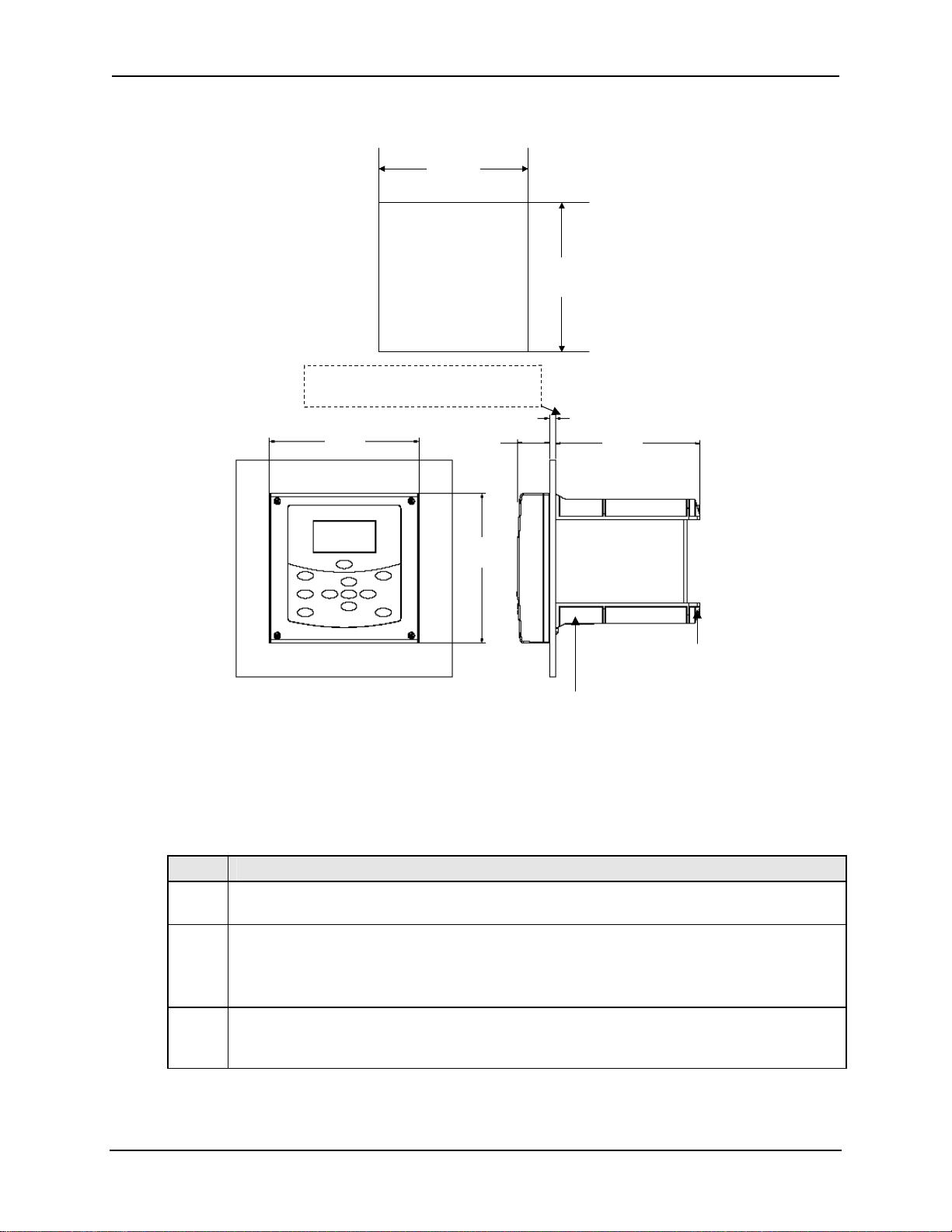
Panel Mounting Dimensions
+1
+1
+1
138
138
138
-0
-0
-0
+.04
+.04
+.04
[5.43]
[5.43]
[5.43]
-0
-0
-0
+1
+1
+1
138
138
138
-0
-0
Panel Cutout
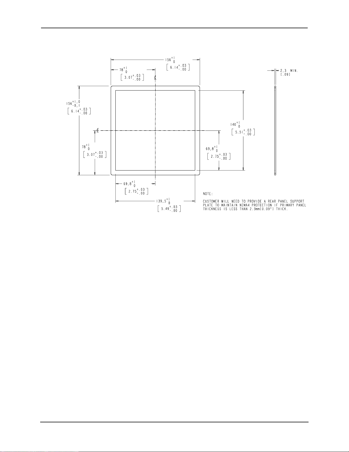
Panel Cutout
Customer will need to provide a rear panel support
Customer will need to provide a rear panel support
plate to maintain NEMA4 protection if primary
plate to maintain NEMA4 protection if primary
panel thickness is less that 2.3mm [0.09”] thick
panel thickness is less that 2.3mm [0.09”] thick
156
156
[6.14]
[6.14]
33.5
33.5
[1.32]
[1.32]
-0
+.04
+.04
+.04
[5.43]
[5.43]
[5.43]
-0
-0
-0
CUSTOMER PANEL
CUSTOMER PANEL
1.6[.06] to 6.35 MAX[0.25]
1.6[.06] to 6.35 MAX[0.25]
152
152
[5.98]
[5.98]
Figure 3-1 Panel Mounting Dimensions (not to scale)
Panel Mounting Procedure
Table 3-2 Panel Mounting Procedure
Step Action
Mark and cut out the analyzer hole in the panel according to the dimension information
1
in Figure 3-1.
Orient the case properly and slide it through the panel hole from the front.
2
Customer will need to provide a rear panel support plate to maintain NEMA4
protection if primary panel thickness is less that 2.3mm [0.09”] thick –
See Figure 3-2.
Remove the mounting kit from the shipping container and clamp the edges of the
3
cutout between the case flange and the supplied U-bracket that is fastened to the rear
of the case using (2) M5 X 16mm long screws and (2) M5 lock washers supplied.
156
156
[6.14]
[6.14]
(4) 22.22[.87] holes for
(4) 22.22[.87] holes for
lead wires and conduit fittings
lead wires and conduit fittings
(conduit fittings supplied by user)
(conduit fittings supplied by user)
January 2009 UDA2182 Universal Dual Analyzer Product Manual 11
Page 24
Unpacking
Rear Panel Support Plate Dimensions
Figure 3-2 Rear Panel Support Plate Dimensions
12 UDA2182 Universal Dual Analyzer Product Manual January 2009
Page 25
Unpacking
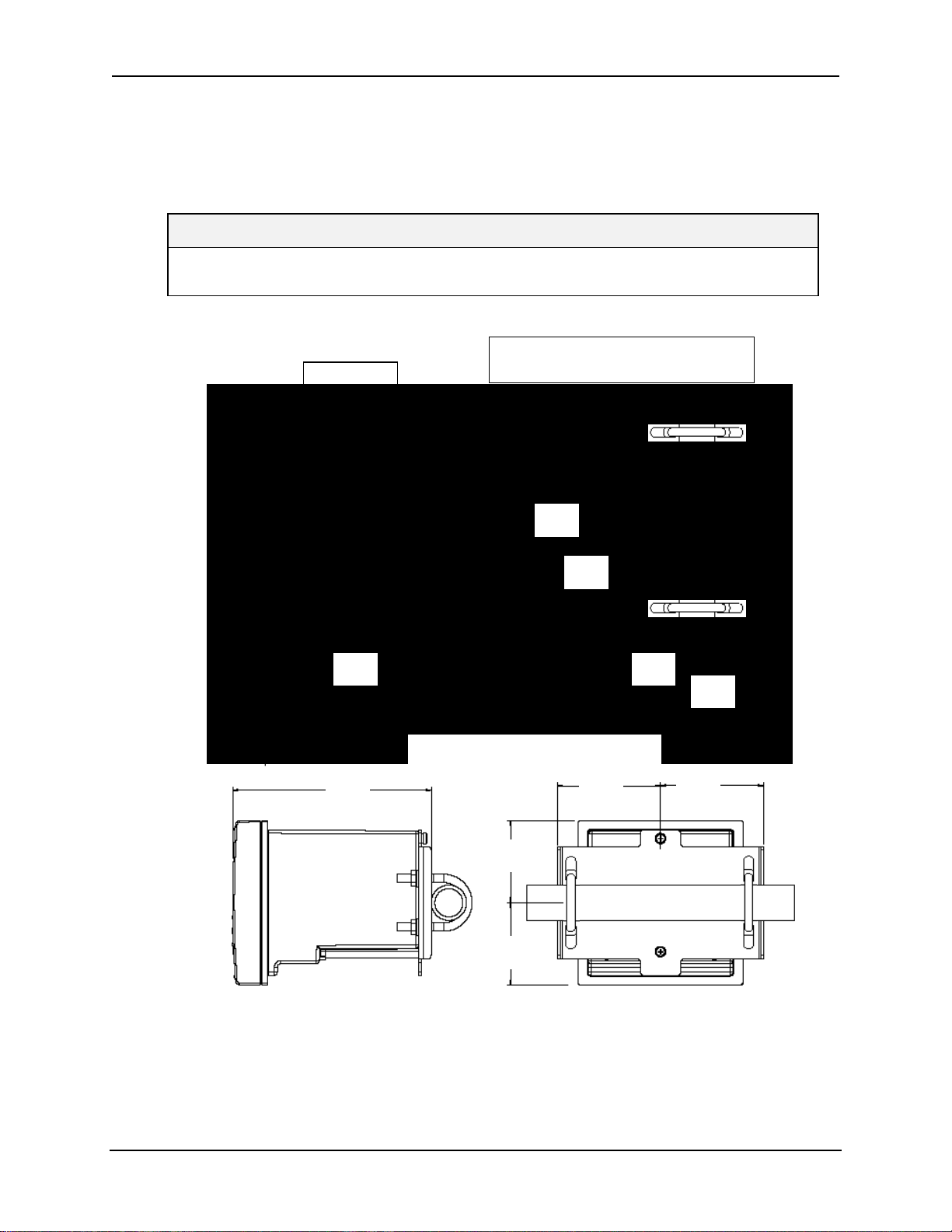
Pipe Mounting
The analyzer can be mounted vertically or horizontally on a pipe. Use the bracket and
hardware supplied in the mounting kit.
Select 1 inch or 2 inch U-Bolts.
ATTENTION
Pipe mounting is not recommended if the pipe is subject to severe vibration. Excessive
vibration may affect system performance.
M5 X 10mm long screw with M5 lock washer (2 places)
M5 X 10mm long screw with M5 lock washer (2 places)
Note orientation of hole and slot in mounting bracket.
Note orientation of hole and slot in mounting bracket.
Hole is to be in the upper position.
M8 Nut
M8 Nut
M8 Lock Washer
M8 Lock Washer
M8 Flat Washer
M8 Flat Washer
Hole is to be in the upper position.
195.1
195.1
[7.68]
[7.68]
Do not over
Do not over
tighten fasteners
tighten fasteners
4.5Nm (40 Lb-in) of
4.5Nm (40 Lb-in) of
torque max.
torque max.
188.1
188.1
[7.40]
[7.40]
188.1
188.1
[7.40]
[7.40]
97.5
97.5
[3.84]
[3.84]
77.4
77.4
[3.05]
[3.05]
1 or 2 inch Vertical Rear Pipe Mounting
1 or 2 inch Vertical Rear Pipe Mounting
97.5
97.5
[3.84]
[3.84]
78
78
[3.07]
[3.07]
78
78
[3.07]
[3.07]
1 or 2 inch Horizontal Rear Pipe Mounting
1 or 2 inch Horizontal Rear Pipe Mounting
97.5
97.5
[3.84]
[3.84]
156
156
[6.14]
[6.14]
Figure 3-3 Pipe Mounting Dimensions (not to scale)
January 2009 UDA2182 Universal Dual Analyzer Product Manual 13
Page 26
Unpacking
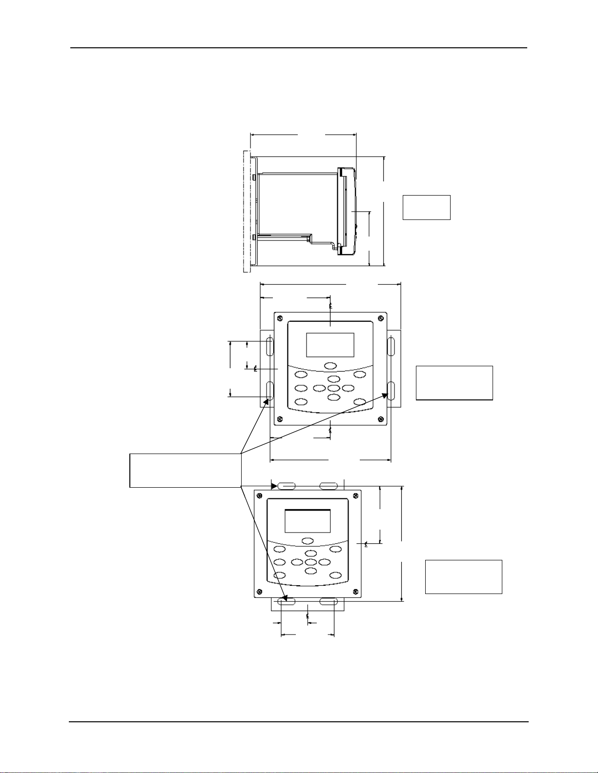
Wall Mounting Dimensions
The analyzer can be mounted on a wall. Use the bracket and hardware supplied in the
mounting kit.
188.1
188.1
[7.40]
[7.40]
195.06
195.06
[7.680]
38.5
38.5
[1.51]
[1.51]
97.5
97.5
[3.84]
[3.84]
195.1
195.1
[7.68]
[7.68]
83.9
83.9
[3.30]
[3.30]
97.53
97.53
[3.840]
[3.840]
195.1
195.1
[7.68]
[7.68]
[7.680]
Left hand
Left hand
Side View
Side View
77
77
[3.03]
[3.03]
Four slots in bracket for
Four slots in bracket for
6.0mm [1/4 “] dia mounting
6.0mm [1/4 “] dia mounting
bolts supplied by customer
bolts supplied by customer
38.5
38.5
[1.52]
[1.52]
83.9
83.9
[3.30]
[3.30]
77
77
[3.03]
[3.03]
167.6
167.6
[6.60]
[6.60]
83.9
83.9
[3.30]
[3.30]
167.8
167.8
[6.61]
[6.61]
Front View
Front View
Mounting Bracket
Mounting Bracket
Horizontal
Horizontal
Front View
Front View
Mounting Bracket
Mounting Bracket
Vertical
Vertical
Figure 3-4 Wall Mounting Dimensions (not to scale)
14 UDA2182 Universal Dual Analyzer Product Manual January 2009
Page 27

Power Wiring
4 Power Wiring
4.1 Overview
Introduction
This section contains instructions for installing ac power wiring for the Analyzer, in
preparation for performing configuration setup as described in Section 6.
We recommend that you wait to install input and output wiring (See Section 7) until after
Configuration Setup. During configuration the software will determine for you, which
relay to use for each feature.
What’s in this section?
The topics in this section are listed below.
Topic See Page
4.1 Overview 15
4.2 General Wiring Practices 16
4.3 Power Wiring Considerations 17
4.4 Installing Power Wiring 17
January 2009 UDA2182 Universal Dual Analyzer Product Manual 15
Page 28
Power Wiring
4.2 General Wiring Practices
WARNING
Safety precaution
Qualified personnel should perform wiring only.
WARNING
A disconnect switch must be installed to break all current
carrying conductors. Turn off power before working on
conductors. Failure to observe this precaution may result in
serious personal injury.
WARNING
An external disconnect switch is required for any hazardous
voltage connections to the relay outputs.
Avoid damage to components
ATTENTION
This equipment contains devices that can be damaged by electrostatic discharge (ESD). As
solid-state technology advances and as solid-state devices get smaller and smaller, they
become more and more sensitive to ESD. The damage incurred may not cause the device to
fail completely, but may cause early failure. Therefore, it is imperative that assemblies
containing static sensitive devices be carried in conductive plastic bags. When adjusting or
performing any work on such assemblies, grounded workstations and wrist straps must be
used. If soldering irons are used, they must also be grounded.
A grounded workstation is any conductive or metallic surface connected to an earth ground,
such as a water pipe, with a 1/2 to 1 megohm resistor in series with the ground connection. The
purpose of the resistor is to current limit an electrostatic discharge and to prevent any shock
hazard to the operator. The steps indicated above must be followed to prevent damage and/or
degradation, which may be induced by ESD, to static sensitive devices.
Wiring for immunity compliance
In applications where either the power, input or output wiring are subject to
electromagnetic disturbances, shielding techniques will be required. Grounded metal
conduit with conductive conduit fittings is recommended.
Connect the AC mains through a fused disconnect switch.
Conform to code
Instrument wiring should conform to regulations of the National Electrical Code.
16 UDA2182 Universal Dual Analyzer Product Manual January 2009
Page 29
Power Wiring
4.3 Power Wiring Considerations
Recommended wire size
Observe all applicable electrical codes when making power connections. Unless locally
applicable codes dictate otherwise, use 14-gauge (2.081 mm
including protective earth.
Power supply voltage and frequency within specs
The power supply voltage and frequency must be within the limits stated in the
specifications in Section 2.
4.4 Installing Power Wiring
Procedure
WARNING
Turn power off at mains before installing AC Power Wiring.
Do not remove boards with power ON.
WARNING
The ground terminal must be connected to a reliable earth
ground for proper operation and to comply with OSHA and
other safety codes. If metal conduit is used, connect a bonding
wire between conduits. Do not rely upon the conductive coating
of the instrument case to provide this connection. Failure to
observe this precaution may result in serious personal injury.
2
) wire for ac power,
CAUTION
To avoid damage to the case when connecting to a rigid metallic conduit system, the
conduit hub must be connected to the conduit before the hub is connected to the
enclosure
Table 4-1 Procedure for installing AC Power Wiring
Step Action
Check the tag on the outside of the case to be sure that the voltage rating of the unit
1
matches the input voltage at your site.
ATTENTION
The Unit may be damaged if you apply power with the wrong voltage.
2 With Power off, open the case:
• Loosen the four captive screws on the front of the bezel.
• Grasp the bezel on the right side. Lift the bezel gently and swing the bezel open to the left.
Refer to Figure 7-1 for the location of the printed wiring board retainer. Loosen the two
3
January 2009 UDA2182 Universal Dual Analyzer Product Manual 17
Page 30

Power Wiring
Step Action
screws that hold the retainer and slide the retainer to the left until the retainer tabs
disengage from the terminal boards.
Refer to Figure 7-1 for the location of the Power Supply/Analog Output/Relay Output board.
4
Insert a screwdriver into the hole in the middle of the terminal board and pull out gently.
Slide the board half way out. There is a notch in the terminal board into which you can slide
the retainer tabs and hold the board in place while wiring.
Install a fused disconnect switch in the power line that will be connected to the Analyzer.
5
•If a 230/240 Vac line is to be connected, use a 0.15 amp fuse.
•If a 110/120 Vac line is to be connected, use a 0.30 amp fuse.
Fuse must be a Time-Delay or Slo-Blo type.
Each unit has (4) 22.22mm [.87"] dia. holes on the bottom of the unit for lead wires and
6
conduit fittings. Conduit fittings to be supplied by the user.
Feed the power wiring through the wiring port on the bottom of the case. Connect the power
wiring to terminals L1 and L2/N as shown in Figure 4-1. Connect the Green safety ground
wire to the grounding stud on the case.
Attention: Terminal 1 must be connected to the ground stud on the grounding bar using
a #14 AWG UL/CSA-approved wire.
Slide the retainer to the left then slide the terminal board back into place. Slide retainer to
7
engage the tabs and tighten the screws.
Close the Bezel and secure four captive screws to a torque value of .20 Nm (1.5 Lb-in).
8
Power up the unit.
Do not apply power until the bezel is closed.
18 UDA2182 Universal Dual Analyzer Product Manual January 2009
Page 31

Power Wiring
13
13
13
Analog Output 1 (+)
Analog Output 1 (+)
Analog Output 1 (+)
Analog Output 1 (+)
Analog Output 1 (–)
Analog Output 1 (–)
Analog Output 1 (–)
Analog Output 1 (–)
Analog Output 2 (+)
Analog Output 2 (+)
Analog Output 2 (+)
Analog Output 2 (+)
Analog Output 2 (–)
Analog Output 2 (–)
Analog Output 2 (–)
Analog Output 2 (–)
Relay Output 1 (N.O. )
Relay Output 1 (N.O. )
Relay Output 1 (N.O. )
Relay Output 1 (N.O. )
Relay Output 1 (COM)
Relay Output 1 (COM)
Relay Output 1 (COM)
Relay Output 1 (COM)
Relay Output 1 (N.C.)
Relay Output 1 (N.C.)
Relay Output 1 (N.C.)
Relay Output 1 (N.C.)
Relay Output 2 (N.O.)
Relay Output 2 (N.O.)
Relay Output 2 (N.O.)
Relay Output 2 (N.O.)
Relay Output 2 (COM)
Relay Output 2 (COM)
Relay Output 2 (COM)
Relay Output 2 (COM)
Relay Output 2 (N.C.)
Relay Output 2 (N.C.)
Relay Output 2 (N.C.)
Relay Output 2 (N.C.)
AC Hot L1
AC Hot L1
AC Hot L1
AC Hot L1
AC N L2
AC N L2
AC N L2
AC N L2
13
12
12
12
12
11
11
10
10
10
10
9
9
9
9
8
8
8
8
7
7
7
7
6
6
6
6
5
5
5
5
4
4
4
4
Case Earth Ground
Case Earth Ground
Case Earth Ground
Case Earth Ground
1
1
1
1
Grounding Stud
Grounding Stud
Grounding Stud
Grounding Stud
on Case
on Case
on Case
on Case
Figure 4-1 Power Wiring
January 2009 UDA2182 Universal Dual Analyzer Product Manual 19
Page 32

Operating the Analyzer
5 Operating the Analyzer
5.1 Overview
Introduction
This section contains instructions for operating the Analyzer.
What’s in this section?
The topics in this section are listed below.
Topic See Page
5.1 Overview 20
5.2 Analyzer Overview 21
5.3 Key Navigation 22
5.4 Displays Overview 23
5.5 Input Displays 25
5.6 PID Displays 26
5.7 Auto Cycle Displays 28
5.8 Pharma Display 33
5.10 Status Display 41
5.11 Event History 46
5.12 Process Instrument Explorer Software 48
20 UDA2182 Universal Dual Analyzer Product Manual January 2009
Page 33

Operating the Analyzer
5.2 Analyzer Overview
The UDA2182 Universal Dual Analyzer is the next level of dual channel analyzers
providing unprecedented versatility and flexibility.
The analyzer can accept single or dual inputs from Honeywell Direct pH, pH from
preamp, ORP (Oxidation Reduction Potential), Contacting Conductivity and Dissolved
Oxygen sensors.
Measurement for Dual channel units can be arranged in any combination of
measurement.
A Communications card provides one Serial Port (RS485) and one Ethernet Port.
Figure 5-1 UDA2182 Operator Interface (all display items shown)
January 2009 UDA2182 Universal Dual Analyzer Product Manual 21
Page 34

Operating the Analyzer
5.3 Key Navigation
Table 5-1 shows each key on the operator interface and defines its function.
Table 5-1 Function of Keys
Key Function
• When process values are on display: Use DISPLAY to cycle between PV
Displays, PID Loop Displays, Auto Cycle Displays, Pharma Displays, Cation
Display
Display, Status Displays and an Event History Display.
• In Setup mode, calibration mode, or calibration edit mode, use DISPLAY to
abort current mode and return to the last accessed online display.
• Engages hold of analog and digital values at their current values and any
relays assigned to alarm events or control are deactivated.
Hold
Setup
Exit
Calibrate
or
ATTENTION:
• Selects the configuration main menu when online, in calibration mode, or at a
calibration submenu.
• In configuration menu, exits submenu to parent menu. If at configuration main
menu, selects current online display.
• In configuration edit mode, aborts editing of current parameter.
• When online, acknowledges current alarm event to stop the flashing of the
relay indicator and status message area.
• Selects the calibration main screen when online, in configuration mode or at
another calibration screen.
• When a Setup configuration menu or configuration edit screen is on display:
Use Up/Down keys to highlight a different item.
• In configuration edit mode, either selects the parameter character or
numerical digit to change or selects an enumerated parameter value:
Use Up/Down key to increment the value of the digit at the cursor.
Increases/decreases the selected parameter value.
• When in display mode, use up/down keys to adjust the contrast on the screen.
This takes precedence over the FAILSAFE function.
• In configuration edit mode, selects the character or digit to change.
or
Enter
22 UDA2182 Universal Dual Analyzer Product Manual January 2009
• In calibration mode, selects the next or previous calibration screen.
• In display mode, selects a single or dual display on a unit with dual input.
• In configuration menu, selects edit mode for selected parameter.
• In configuration edit mode, saves edited parameter selection or value.
• In calibration mode, selects parameters to reset and the next calibration
screen.
Page 35

Operating the Analyzer
5.4 Displays Overview
Viewing the Displays
To view display screens, push the
screens which show the current status of pH/ORP, Conductivity, or Dissolved Oxygen
Concentration. There are displays for PID, Auto Cycle, and Pharma. It also lets you view a Status
Display and an Event History Display.
Displays Shown
One Input - When only one input board is installed, the online screen displays one PV and its
units in a larger font size (Section 5.5).
Two Inputs - When two input boards are installed, the online screen displays two PVs and its
units in a smaller font size. Press
PID - When PID 1 or 2 is active (Section 5.6 ), there is a display screen for each. There is a sub-
screen that allows editing of the Setpoint value, Setpoint Source, Control Mode, and Output
value. You can also enable or disable Accutune and Tune set.
Auto Cycle – When Auto Cycle 1 or 2 is active (Section 5.7), there is a display screen for each.
There is a sub-screen that allows you to start or stop the Cycle.
Pharma – Enabled in Conductivity inputs. Each Pharma screen monitors standard procedure
stages for determining Purified Water. There is a sub-screen that allows you to change the
Pharma Test Stage and adjust the Pct Warning value (Stage 1), Test µS/cm value (Stage 2) and
the Test pH (Stage 3). (See Section 5.8 for details)
Cation Calc – When cation Calc 1 or 2 is active there is a display screen for either cation
or degassed CO2 measurement. (Section 5.9)
Status Display
Relay States, Monitor Status, Math Values, Aux Values, Variables, Comm Status, System Status,
and Calculated Values. (Section 5.10)
Event History - Event History records events with timestamp. (Section 5.11) Events recorded
include setup change, power on, calibrations (no values) and alarms with detail available on alarm
type and source by scrolling and selecting event name. Status warns of event history at 50% and
90% and when erasing old records.
- of Alarms Status, PID Alarms Status, Logic Status, Input Status, Output Levels,
Contrast Adjustment
Display
key. Pushing the Display key repeatedly scrolls through
to see single PV screens (Section 5.5).
When viewing a PV or Control display, you can adjust the contrast by pressing the or key.
Bargraphs Overview
Output Bargraphs will represent up to three current output values. On the display, the Bargraphs
are the output in Engineering Units. The corner annunciators are the physical relay states (light –
de-energized, dark – energized). The third output and the 3 and 4 relays are shown only when the
source other than NONE is selected.
Menu Indicators
An upward-pointing arrow indicator above the menu at the left end of the header appears when
there are currently menu items above the screen accessible by moving the cursor up.
A downward-pointing arrow indicator below the menu at the left end of the status footer appears
when there are currently menu items below the screen accessible by moving the cursor down.
Use the keys.
January 2009 UDA2182 Universal Dual Analyzer Product Manual 23
Page 36

Operating the Analyzer
Online Functions
Table 5-2 Display Details Functions
Detail Function
Process Variable
Values
Tag Name
PV Temperature
Status Messages
When two input boards are installed, the default online screen displays both PVs and
their units of measure, as determined by the input boards, the probe (if memoryembedded) or any measurement configuration options that may be available. When
only one input board is installed, the default online screen displays one PV and its units
in a larger font size.
The currently selected PV type determines the numerical format and the units of
measure on the online PV display. Measured PV is generally displayed in the highest
decimal precision possible with five digits and has a potentially displayable range of
0.0000 to 99999. The exceptions are dissolved oxygen, pH, ORP and temperature,
which are displayed with fixed decimal precision.
PV Type determines specific ranges and in the case of Conductivity, cell constant
determines available PV Types. Each PV measurement and display is updated every
500ms maximum. Each temperature measurement and display is updated every 10
seconds maximum.
See the Specific Input configuration for available ranges. (Section 6.6)
The real-time displays of process values show the instrument’s tag name (or other
configurable fixed sixteen-character string) at the top of the screen.
Each PV value is accompanied by a temperature value for all measurements except
ORP, as ORP probes do not contain temperature sensors and no measurement
compensation for temperature is required. Temperature values are displayed in units of
degrees Fahrenheit or degrees Celsius as determined by configuration.
Measured temperature is always expressed in fixed tenths decimal precision and has a
displayed range according to input type:
PH/ORP
Conductivity
A text string appears on the bottom of all displays. Online displays provide messages
relaying online diagnostics, alarms and other events. Offline screens display messages
relevant to data entry and calibration. See Section 12.
Dissolved Oxygen
-10.0 to 110.0°C or 14.0 to 230.0°F
0 to 140.0°C or 32.0 to 284°F
0 to 60.0°C or 32 to 140°F
Bargraphs
The Bargraphs will represent up to three output values. The corner indicators represent
the physical state of the Relay Outputs [1, 2, 3, and 4].
*Note that all values and indicators on the main (input) display screen are maintained in the input setup
group.
24 UDA2182 Universal Dual Analyzer Product Manual January 2009
Page 37

Operating the Analyzer
5.5 Input Displays
Two Input Display
Press
Display
Relay 1 Physical State
Relay 1 Physical State
White – De-energized
White – De-energized
Black - Energized
Black - Energized
Solution Temperature
Solution Temperature
Compensation PV1
Compensation PV1
Output 1 Bargraph*
Output 1 Bargraph*
Output 2 Bargraph*
Output 2 Bargraph*
Solution Temperature
Solution Temperature
Compensation PV2
Compensation PV2
Relay 2 Physical State
Relay 2 Physical State
White – De-energized
White – De-energized
Black - Energized
Black - Energized
Single Displays
. You will see:
PV UnitsTag NamePV1 Value PV Temperature
PV UnitsTag NamePV1 Value PV Temperature
UDA2182
1
1
7.00
7.00
C
C
4H9
4H9
2
2
1
11
0.000
0.000
NaCl
NaCl
2
2
PV2 Value Diagnostics or Alarm Message
PV2 Value Diagnostics or Alarm Message
*On the display, the bargraphs are the outputs in Engineering Units,
*On the display, the bargraphs are the outputs in Engineering Units,
the corner annunciators are the physical relay states.
the corner annunciators are the physical relay states.
UDA2182
pH
pH
NO
NO
Probe PV 2 Fault
Probe PV 2 Fault
25.0
25.0
µS/cm
µS/cm
0.0
0.0
ºC
ºC
ºC
ºC
3
3
3
33
4
4
Figure 5-2 Example – Two Input Display
Relay 3 Physical State
Relay 3 Physical State
White – De-energized
White – De-energized
Black - Energized
Black - Energized
Output 3 Bargraph*
Output 3 Bargraph*
Relay 4 Physical State
Relay 4 Physical State
White – De-energized
White – De-energized
Black - Energized
Black - Energized
For single displays on a two input unit;
Press to display a single display for Input 1.
Press again to display a single display for Input 2.
Press
again to return to a Dual Display.
January 2009 UDA2182 Universal Dual Analyzer Product Manual 25
Page 38

Operating the Analyzer
5.6 PID Displays
Overview
When PID 1 or 2 is active - there is a display screen for each. There is a sub-screen that
allows editing of the Setpoint value, Setpoint Source, Control Mode, and Output value.
You can also enable or disable Accutune and Tune Set.
Selecting Control Display
Press
Display
until you see the PID Display screen. If PID 1 and 2 have been configured,
press DISPLAY again. In each instance, you can edit some control parameters. See Table
5-3.
PID Loop
PID Loop
1 or 2
Relay 1 Physical State
Relay 1 Physical State
White – De-energized
White – De-energized
Black - Energized
Black - Energized
Setpoint Indicator
Setpoint Indicator
Relay 2 Physical State
Relay 2 Physical State
White – De- energized
White – De- energized
Black - Energized
Black - Energized
PV1 or PV 2 Value Control Mode
PV1 or PV 2 Value Control Mode
1
1
0.00
0.00
1
11
0.00
0.00
2
2
Working Setpoint Value*
Working Setpoint Value*
1 or 2
PID LOOP 1
PID LOOP 1
pH
pH
Auto
Auto
0.0
0.0
PV Units
PV Units
Auto or Manual*
Auto or Manual*
Relay 3 Physical State
3
3
2
22
4
4
Relay 3 Physical State
White – De- energized
White – De- energized
Output Value*
Output Value*
Relay 4 Physical State
Relay 4 Physical State
White – De- energized
White – De- energized
Black - Energized
Black - Energized
Black - Energized
Black - Energized
*These Control parameters can be edited. See Table 5-3.
Figure 5-3 PID Loop 1 Edit Display screen example
26 UDA2182 Universal Dual Analyzer Product Manual January 2009
Page 39

Operating the Analyzer
Changing Parameters on the PID Display
When either PID Display is on the Display screen, you can edit the Setpoint value,
Setpoint Source, Control Mode, and the Output value. You can also enable or disable
Accutune and Tune Set.
Table 5-3 Changing PID Parameters on the Display
Press Action
Enter
to access the PID Parameters. You will see:
PID LOOP 1
PID LOOP 1
LSP
LSP
SP Source Local SP
SP Source Local SP
Mode
Mode
Output
Output
Tune Set 2 Disable
Tune Set 2 Disable
0.00
0.00
Manual
Manual
0.00
0.00
Example – PID Loop 1 Edit Display
to highlight the parameter you want to change.
Enter
to access the value or selection of each.
to change the value or selection.
Note: Output can only be changed in Manual mode.
Refer to “Section 6.4.1 – ”General Rules for Editing”.
Enter
Display
to make the edit permanent.
to return to the selected PID Display.
January 2009 UDA2182 Universal Dual Analyzer Product Manual 27
Page 40

Operating the Analyzer
5.7 Auto Cycle Displays
5.7.1 Overview
Auto Cycling allows each input probe to be automatically rinsed and calibrated on a
recurring schedule, in response to an event, or on demand.
Auto cycling is supported with Setup Menus ( Section 6.15- Auto Cycle Configuration),
Status Displays (Section 5.10 – Status Display) and Operational Displays (Section 5.7 as
well as Event History (Section 5.11) and Calibration History logging (Section 11).
5.7.2 Access to Auto Cycle Displays
• When Auto Cycle is enabled (see Auto Cycling Setup –Section 6.15),
press
Display
until you see:
Relay 1 Physical State
White – De-energized
Black - Energized
Relay 2 Physical State
White – De-energized
Black - Energized
* See Table 5-5.
Figure 5-4 Auto Cycle Display screen example
Step*
1
Auto Cycle 1 or 2Sequence
AUTO CYCLE 1
Cycle Stop
1
0.00
Next 06-05-01 12:00:00PM
2
Current Clock Time or
remaining Elapsed Time
12:48:27
µS/cm
27.2 ºC
Relay 4 Physical State
White – De-energized
Black - Energized
3
2
Relay 3 Physical State
White – De-energized
Black - Energized
PV UnitsPV
Input Temperature
Date and Time of next cycle;
Cycle Timer is Off:
or Fail Detail Message
4
28 UDA2182 Universal Dual Analyzer Product Manual January 2009
Page 41

Operating the Analyzer
5.7.3 How it works
Each occurrence of a sequence of actions for the cleaning and calibration of a probe is a
cycle. The status message “Auto Cycle n Active” appears for the duration of a nonfailing cycle (where n refers to 1 or 2). Each cycle consists of the following sequence that
will vary depending on the input type and parameters selected:
Cycle Start
Probe Extract (if enabled)
Probe Rinse
Cal pt 1
Cal pt 2 (If the input is pH)
Probe Insert (If enabled)
Resume Delay (If a time is selected)
For a more detailed explanation please refer to Table 5-5.
5.7.4 Displays
The current sequence step is shown in the upper half of the Auto Cycle display.
When Cycle Stop is displayed, the field to the right displays the current clock time in the
format configured in Setup/Maintenance/Clock.
When the cycle is active, the same field provides the remaining elapsed time for the
current sequence step.
The lower half of the Auto Cycle display provides either: the date and time of the next
cycle, an indication that the cycle timer is off; or an auto cycle fail detail message.
January 2009 UDA2182 Universal Dual Analyzer Product Manual 29
Page 42

Operating the Analyzer
5.7.5 Hold Active
If Hold Active is enabled in Auto cycling Setup, then the values remain in the hold state
during auto cycle. When Hold is active on either input, the status message “Hold Active”
is displayed and the specific PV value flashes at a very slow rate.
When Hold is activated manually from the front panel Hold button, the values remain in
the hold state until its state is changed via the front panel again.
5.7.6 Probe Transit
This parameter is available to allow you to automate functions that relate to probe
removal and insertion. Once the probe transit parameter is enabled, the extract wait
source, insert wait source and max transit mins can be selected. The extract wait source
and insert wait source can be set to any digital input so that the extract or insert
operations continue until the selected digital input is low. Once the wait source signal is
low then the probe extraction or insertion sequence step can end or otherwise time out if
the duration of the “max transit mins” is exceeded. If probe transit is enabled and probe
extract src/insert src is set to none, then the probe extract/insert step will occur for the
duration of the max transit mins.
5.7.7 Cycle Start Src
The Auto cycle can be started in one of three ways. It can start upon the occurrence of a
specific digital input changing state from low to high. The cycle can also start when the
cycle timer engages. The cycle can also be manually started from the Auto Cycle display
screen op panel.
5.7.8 Cycle Interval
This parameter enables the cycle timer and allows you to set the Auto cycle to recur at a
period defined by you. If the cycle interval is set to Custom, Monthly, Weekly or Daily
then specific menu items are activated to set-up cycle start and period times. You can
select a cycle interval appropriate to the application.
5.7.9 Rinse Cycle Cnt
This parameter allows you to select when or if a rinse sequence occurs during a cycle. A
selection of 0 indicates that a rinse sequence will not occur. A selection of 1 indicates
that a rinse sequence occurs during every cycle. There is an option to set the rinse
sequence for less frequent times by selecting values from 2 to 100. For example; a
selection of 3 means that the rinse sequence will occur every 3rd cycle.
5.7.10 Rinse Mins
This parameter allows you to select the duration of a rinse.
5.7.11 Resume Dly Mins
This parameter allows you to specify a delay time before the cycle is completed.
30 UDA2182 Universal Dual Analyzer Product Manual January 2009
Page 43

Operating the Analyzer
5.7.12 Manual Starting/Stopping the Auto Cycle
Pressing Enter on the Auto Cycle Operational Display brings up an operator panel menu
that enables you to manually start or stop an auto cycle sequence or place the cycle in
Hold, regardless of whether or not the cycle timer is configured. Start cycle is visible
when the Auto Cycle is not active and Stop Cycle is visible during an auto cycle.
The objective of a Cycle Stop is to terminate the Auto Cycle by putting the probe back
into the process. The selection of Cycle Stop causes the sequencer to proceed directly to
the Probe Insert stage, if Probe Transit is enabled, and then to the Resume Delay stage.
Selecting Stop Cycle during Probe Insert advances the sequencer to resume delay.
Finally, a Stop Cycle selection during Resume Delay will stop the cycle completely.
If enabled, the cycle timer will still trigger a cycle at the configured time provided the
sequencer returns to Cycle Stop beforehand. Otherwise, the cycle will execute at the next
available time.
The Hold Cycle selection is available in both auto cycle active and inactive states. When
inactive, enabling Hold Cycle will hold the sequencer at the beginning of the sequence
until released to continue by disabling the Hold Cycle.
Selecting Hold Cycle during an active cycle will suspend the sequencer at the current
step as well as the step timer. Disabling Hold Cycle will resume the sequencer and step
timer. During cycle Hold, the status bar will show the message “Auto Cycle in hold”.
Table 5-4 Manually Starting/Stopping the Auto Cycle
Press Action
Enter
to access the Auto Cycle Operator Panel. You will see:
1
1
1
1
1
1
1
1
2
2
2
2
AUTO CYCLE
AUTO CYCLE 1
AUTO CYCLE
AUTO CYCLE 1
Cycle Stop
Cycle Stop
0.00
0.00
0.00
0.00
Next 06.03.29 13:50:24
Next 06.03.29 13:50:24
12:48:27
12:48:27
NoStart Cycle
NoStart Cycle
NoStart Cycle
µS/cm
µS/cm
µS/cm
µS/cm
NoHold Cycle
NoHold Cycle
NoHold Cycle
27.2 ºC
27.2 ºC
27.2 ºC
27.2 ºC
3
3
3
3
2
2
2
2
4
4
4
4
Example – AUTO CYCLE 1 Operator Panel
Note: The item “Start Cycle” is replaced with “Stop
Cycle” when the cycle is active.
To access Start Cycle or Hold Cycle
Enter
Enter
to access the Start Cycle/Hold Cycle selection.
to change the selection from NO to YES.
Start Cycle
Start Cycle
to Start or Hold the Auto Cycle.
YES
YES
NoHold Cycle
NoHold Cycle
See Table 5-5 for sequencer steps.
January 2009 UDA2182 Universal Dual Analyzer Product Manual 31
Page 44

Operating the Analyzer
5.7.13 Auto Cycle Fail
The status message “Auto Cycle n Fail” is displayed during a fail state. Once detected,
the current cycle proceeds immediately to the Probe Insert step (if enabled) or to the
Resume Delay step. The fail state remains for the duration of the Resume Delay,
whereupon the fail state returns to zero and the fail message is cancelled.
A fail state also provides a detail message in the lower half of the Auto Cycle display
regarding the specific reason for the error. These messages are listed in Section 12.4.
The digital output “AC n Fail” is also available and is active whenever an auto cycle
failure has occurred. The auto cycle digital outputs: AC n Extract, AC n Rinse, AC n Cal
Pt 1 and AC n Cal and AC n Cal 2 are available as relay digital input sources (See Table
6-4) to control the operation of valves and solenoids for exposure to rinse water and
buffer solutions or air to accomplish the automatic probe rinse and calibration functions.
5.7.14 Conditional Sequencer Steps
Table 5-5 Conditional Sequencer Steps for Auto Cycle
Step AC n
Extract
Cycle Stop 0 0 0 0 Inactive Cycle inactive
Cycle Start
(transitional)
Probe Extract 1 0 0 0 Active Probe Transit is enabled
Probe Rinse 1 1 0 0 Active Rinse Cycle Cnt > 0 and enables
Cal Point 1 1 1 1 0 Active Rinse timer expires if enabled
Cal Point 2 1 1 0 1 Active Rinse timer expires or Cal 1
Probe Insert 0 1 0 0 Active Auto Cycle Fail
Resume Delay 0 0 0 0 Active Auto Cycle Fail
0 0 0 0 Active Operator panel Cycle Start is Yes
AC n
Rinse
AC n
Cal
AC n
Cal 2
Output
Hold
State
(if
enabled)
Condition
or Cycle Start Src state is 1
or cycle timer engages
current cycle
and if Probe Transit enabled,
Extract Wait Src is None or state is
1 or Max Transit Timer expires
and Cal 1 (Cal) Cycle Cnt > 0 and
enables current cycle
complete
and Cal 2 Cycle Cnt > 0 and
enables current cycle
or Probe Transit is enabled
or Rinse timer expires or Cal 1 or
Cal 2 complete
and Insert Wait Src is None or state
is 1 or Max Transit Timer expires
32 UDA2182 Universal Dual Analyzer Product Manual January 2009
Page 45

Operating the Analyzer
5.8 Pharma Display
5.8.1 Overview
The Pharma Parameter is available when a Conductivity Input is enabled. Pharma
supports USP (United States Pharmacopoeia) and PhEur (Pharmacopoeia Europa)
standard procedure stages for determining Purified Water.
Selecting Pharma Type USP or PhEur (in Section 6.6 – Conductivity Input
Configuration) enables the Pharma monitor screen and adds it to the sequence of displays
accessed by each press of the Display button.
Also, configure Pharma PV High, Pharma PV Low, and Pharma Timer Minutes in this
section.
5.8.2 How it works
Pharmacopoeia Test Procedure
For Procedure steps in each stage, refer to UPS section <645> Test Procedure for
Purified Water and Water for Injection. The procedure for this determination involves a
series of three stages or tests. If the sample does not pass the Stage 1 conductivity
requirement, the State 2 test can be initiated. If the Stage 2 requirements are not met,
then the Stage 3 test can be initiated. If Stage 3 requirements are not met, the sample is
not Purified Water.
In Stage 1 the non-temperature-compensated conductivity reading is compared to the
value specified in the USP standard for a particular temperature. If the measured
conductivity is not greater than the table value, the water meets the requirements of the
test for conductivity and the Pharma test is complete. If the conductivity is higher than
the table value, then the user can manually proceed with Stage 2.
To complete stage 2, transfer a sufficient amount of water (100 mL or more) to a suitable
container, and stir the test specimen. While maintaining the temperature at 25° ± 1°,
begin vigorously agitating the test specimen and note the conductivity reading when the
change is less than 0.1 m S/cm per 5 minutes. If the conductivity is not greater than 2.1
m S/cm, the water meets the requirements of the test for conductivity. If the conductivity
is greater than 2.1 m S/cm, proceed with Stage 3.
Stage 3 must be completed within approximately 5 minutes of the conductivity
determination in stage 2. While maintaining the sample temperature at 25° ± 1°, add a
saturated potassium chloride solution to the same water sample (0.3 mL per 100 mL of
the test specimen), and measure the pH to the nearest 0.1 pH unit, as directed under pH
(791). From USP section <645>, determine the desired conductivity value for a pH value
between 5pH and 7pH. If the measured conductivity is not greater than the conductivity
from USP, section <625>, the water meets the requirements for stage 3 - purified water.
If either the measured conductivity is greater than this value or the pH is outside of the
range of 5.0 to 7.0, the water does not meet the requirements of stage 3 - purified water.
For Procedure steps in each stage, refer to UPS section <645> Test Procedure for
Purified Water and Water for Injection.
January 2009 UDA2182 Universal Dual Analyzer Product Manual 33
Page 46

Operating the Analyzer
The UDA also supports Pharma Europa (PhEur) section 2.2.38, which specifies tests for
determining Highly Purified Water which are identical to USP Stages 1, 2 and 3. PhEur
adds a less demanding test for determining Purified Water at the end of the sequence.
5.8.3 Access to Pharma Display
• When Pharma is enabled (see Input Configuration – Section 6.6) press
Display
until you see:
The measured temperature-
The measured temperature-
uncompensated conductivity
uncompensated conductivity
of the solution in µS/cm
of the solution in µS/cm
Relay 1 Physical State
Relay 1 Physical State
White – De-energized
White – De-energized
Black - Energized
Black - Energized
Left Bar graph -Measured
Left Bar graph -Measured
solution conductivity scaled by
solution conductivity scaled by
the parameter values Pharma
the parameter values Pharma
High and Pharma Low
High and Pharma Low
Left Pointer - Test Limit scaled
Left Pointer - Test Limit scaled
by parameters Pharma High and
by parameters Pharma High and
Pharma Low
Pharma Low
Relay 2 Physical State
Relay 2 Physical State
White – De-energized
White – De-energized
Black - Energized
Black - Energized
1
1
0.966
0.966
1.30
1.30
2
2
Purified water test
Purified water test
limit in units of
limit in units of
measured value
measured value
Pharma
Pharma
Measurement
Measurement
PHARMA 1
PHARMA 1
25.7 ºC
25.7 ºC
Stage 1
Stage 1
74.3%
74.3%
µS/cm
µS/cm
Right Pointer -
Right Pointer -
Warning Limit
Warning Limit
relative to test limit
relative to test limit
3
3
4
4
Relay 4 Physical State
Relay 4 Physical State
White – De-energized
White – De-energized
Black - Energized
Black - Energized
Relay 3 Physical State
Relay 3 Physical State
White – De-energized
White – De-energized
Black - Energized
Black - Energized
The measured temperature
The measured temperature
of solution in system
of solution in system
temperature Units
temperature Units
Right Bar graph – Graphical percent of
Right Bar graph – Graphical percent of
measured conductivity relative to test limit
measured conductivity relative to test limit
Currently select
Currently select
Pharma Test
Pharma Test
The percent of measured
The percent of measured
conductivity relative to test limit
conductivity relative to test limit
5.8.4 Displays
The upper left portion of the screen shows the measured temperature uncompensated
conductivity of the solution in uS/cm for Stage 1. For stage 2 and 3 it displays the test
conductivity value entered during the measurement in stage 2
The process temperature is shown in the upper right of the screen
The lower right portion of the screen shows the USP stage 1 purified water limit, the
stage 2 limit of 2.1 uS/cm and the stage 3 purified water test limit at the measured pH.
When the Pharma n display window is active the various stages can be accessed through
the pharma op panel. (Table 5-6)
Figure 5-5 Pharma Display screen example
34 UDA2182 Universal Dual Analyzer Product Manual January 2009
Page 47
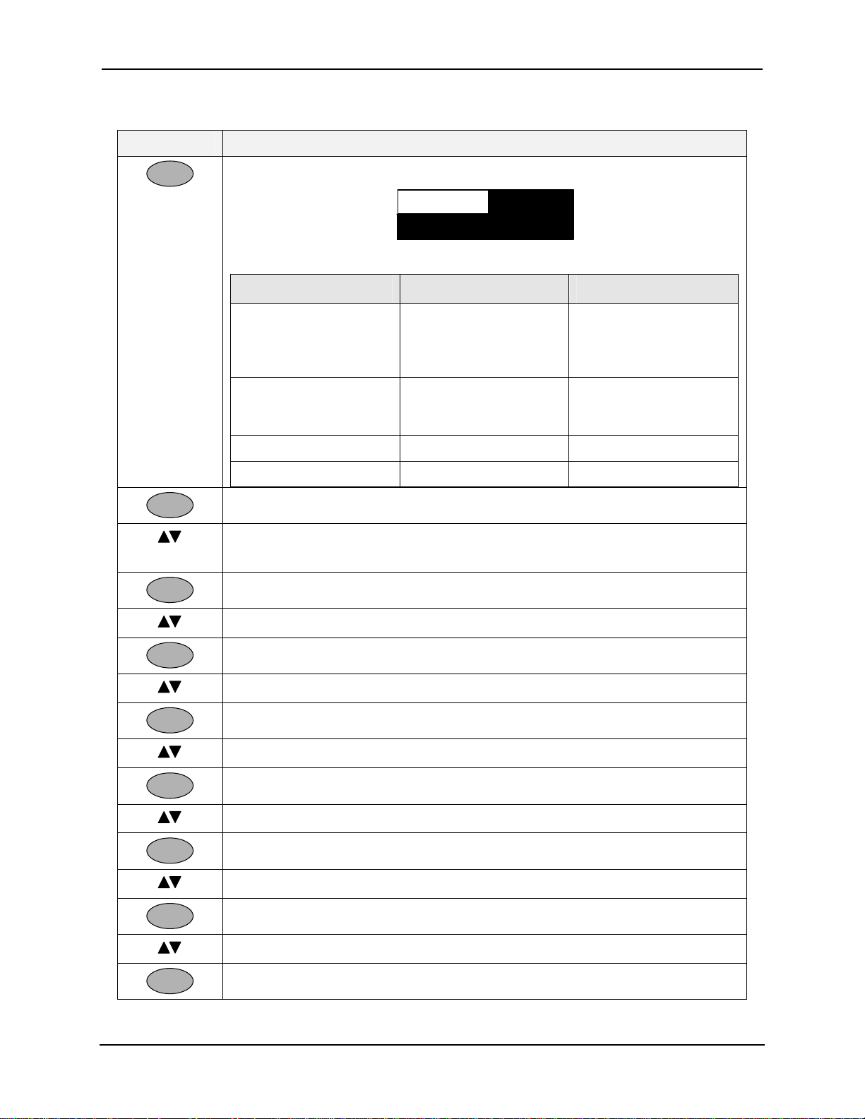
Operating the Analyzer
Table 5-6 Selecting the Pharma Test on Display
Press Action
Enter
Enter
to access the Pharma Op Panel. A pop-up dialog box will appear:
Stage 1Pharma Test
Stage 1Pharma Test
80.00PCT Warn
80.00PCT Warn
Various parameters appear for each stage:
Parameter Values Visibility
Pharma Test Selection Stage 1
Stage 2
Stage 3
Pure H2O (PhEur only)
Pct Warning (% at
which the test warn
occurs)
Test µS/cm
Test pH
to access the Stage selection.
to change the selection to
0 to 100 % Stage 1 only
0 to 10 (default=10)
0 to 14 (default=0)
Always on
Stage 2 only
Stage 3 only
Stage 1, Stage 2, Stage 3 or Pure H2O (PhEur only).
Enter
Enter
Enter
Enter
Enter
Enter
Enter
to make the selection permanent.
to select Pct Warning (Stage 1 only)
to access the Pct Warning Value and allow editing
to select a value
to make the selection permanent.
to select Test µS/cm (After Stage 2 is selected)
to access the Test µS/cm Value
to select a value
to make the selection permanent.
to select Test pH (After Stage 3 is selected)
to access the Test pH Value
to select a value
to make the selection permanent.
January 2009 UDA2182 Universal Dual Analyzer Product Manual 35
Page 48

Operating the Analyzer
5.8.5 Pharma Warning and Fail Signal
The Pharma 1 warning limit is entered from the op-panel for stage 1 and is user
selectable. The digital output “Pharma n Warn” is available (See Digital Source Selection
- Table 6-4).
The Pharma Fail signal is generated whenever any of the following conditions are met:
Stage 1 – Measured Conductivity exceeds 100%
Stage 1 – Temperature not within range of 0-100 degrees C
Stage 2 – Conductivity is 0.1 µS/cm or greater for 5 minutes
Stage 3 – pH not within range of 5 – 7pH
Stage 2 and 3 – Temperature not within range of 24 – 26 degrees C.
The digital output “Pharm n Fail” is available (See Digital Source Selection - Table
6-4).
When the Stage 2 or Stage 3 test is successful, the fail signal is cancelled and the Pharma
Timer begins to count down from the timer minutes value that was configured. When the
Timer countdown is completed, the Pharma function block returns to Stage 1. A fail
signal will return if measured conductivity exceeds 100% or warn signal if measured
conductivity exceeds Pct Warning value.
See Section 12.5 for Pharma Fail Messages.
36 UDA2182 Universal Dual Analyzer Product Manual January 2009
Page 49

Operating the Analyzer
5.9 Cation Calc Display
5.9.1 Overview
This group allows you to configure dual conductivity inputs for cation or degassed CO
2
measurement. The cation selection of Ammonia or Amines will display a calculated pH
value from differential conductivity and provide continuous pH monitoring using
reliable, maintenance free conductivity cells. An outline of the conductivity cells’
installation is illustrated in Figure 5-6.
Flow
Flow
Flow
Valve
Valve
Valve
Flow
Flow
Flow
Meter
Meter
Meter
Cell
Cell
Cell
#2
#2
#2
Cation Exchange Column
Cation Exchange Column
Cation Exchange Column
Cation
Cation
Cation
Conductivity
Conductivity
Conductivity
From Cell #2
From Cell #2
From Cell #2
Inlet
Inlet
Inlet
Specific
Specific
Specific
Conductivity
Conductivity
Conductivity
From Cell #1
From Cell #1
From Cell #1
Cell
Cell
Cell
#1
#1
#1
Reboiler
Reboiler
Reboiler
Gasses
Gasses
Gasses
Cell
Cell
Cell
#3
#3
#3
Degassed
Degassed
Degassed
Conductivity
Conductivity
Conductivity
From Cell #3
From Cell #3
From Cell #3
Drain
Drain
Drain
UDA for Cation Conductivity UDA for Degassed CO
UDA for Cation Conductivity UDA for Degassed CO
UDA for Cation Conductivity UDA for Degassed CO
2
2
2
Figure 5-6 UDA for Cation and Degassed CO2
5.9.2 How it works
UDA2182 will monitor on-line treated water for Specific Conductivity and Cation bed
discharge conductivity, using reliable and maintenance free Honeywell conductivity
cells, and calculate the pH, using the assumption that the water is pure water with Amine
type treatment chemical and residual trace un-removed salts.
pH Calculation from Cation and Specific Conductivity
The equipment consists of Cell #1 which is used for specific conductivity determination
of the influent water sample. The water sample is then passed through a strong acid
cation exchange resin which replaces all cations in the influent stream with hydrogen ion.
On passing though the resin, a second Cell #2 is used to measure the effluent or cation
conductivity. These two measurements in combination are useful for measuring the
amount of base contained in the influent sample and the extent of contamination by
unwanted salts such as sodium chloride, sodium sulfate, etc.
January 2009 UDA2182 Universal Dual Analyzer Product Manual 37
Page 50

Operating the Analyzer
Degassed CO2
The dual input UDA can also be configured for degassed CO2 measurement by
employing cells #2 and #3. Here the cation effluent stream is degassed of CO2, typically
by heating the cation effluent stream to a near boiling temperature. This heating step
results in CO2 out-gassing. The resulting 25°C compensated conductivity measurement
of Cell #3 is lower in value in proportion to the amount of dissolved CO2.
5.9.3 pH Calculation from Specific and Cation Conductivity Setup
Connect cell 1 to input 1 and cell 2 to input 2. Follow the appropriate instructions to
configure the UDA for Cation Calc (See Section 6.18 – Maintenance Configuration.)
Under the sub menu selection of Inputs, the Cation Calc parameter offers two possible
selections.
1. pH Ammonia: Specific conductivity temperature compensation assumes
ammonia (NH3) is the base reagent. In addition to display of conductivity
values, this selection provides for determination and display of solution
pH value.
2. pH Amine pH: Specific conductivity temperature compensation assuming
a generic amine base. These include any one or combination of the
following amines:
Hydrazine
Morpholine
Ethanolamine
Aminomethylpropanol
Methoxypropylamine
4-aminobutanol
5-aminopentanol
Diaminopropane
Cyclohexylamine
Methylamine
Dimethylamine
1,5-diaminopentane
Piperidine
Pyrrolidine
This generic selection employs ammonia temperature compensation and
optimizes pH calculation for these base reagents.
38 UDA2182 Universal Dual Analyzer Product Manual January 2009
Page 51

Operating the Analyzer
Note: The relationship between the electrolytic conductivity and the pH of ammonia and amines is well
established in the technical literature. It must be understood that the UDA was designed for accurate
results over the pH range of 8 to 10.5 based on ammonia or amine chemistries. Other chemistries such as
phosphate or systems that employ alternative anions, such as borate, cannot be expected to realize results
with similar accuracy.
Standardization for cations
The UDA allows for a sample calibration of the cation pH value. Here an independent
sample is withdrawn from the sampling equipment and pH is determined with equipment
of known accuracy. This independent pH value is then entered into the UDA as a pH
calibration constant. To avoid process pH changes during standardization, it is very
desirable to complete the sample extraction, independent measurement and UDA update
as soon as possible.
5.9.4 Calibration
For Calibration procedure, refer to Section 8.7.7 Cation pH Calibration.
5.9.5 CO2 by Degassed Conductivity
The UDA can be configured for CO2 determination by degassed conductivity. The cation
conductivity cell is connected to Input 1 and the degassed sample conductivity cell is
connected to channel 2. The UDA performs HCl temperature compensation of both
measurements to 25°C. The difference between the cation and degassed 25°C values is
taken and ppb CO2 is determined by ASTM D 4519.
5.9.6 Access to Cation Display
• When Cation Calc is enabled (See Section 6.18 – Maintenance
Configuration), press
PV 1 Value
PV 1 Value
Relay 1 Physical State
Relay 1 Physical State
White – De-energized
White – De-energized
Black - Energized**
Black - Energized**
Specific Conductivity
Specific Conductivity
Output 1 Bar graph
Output 1 Bar graphOutput 1 Bar graph
Output 2 Bar graph
Output 2 Bar graph
PV 2 Value
PV 2 ValuePV 2 Value
Relay 2 Physical State
Relay 2 Physical State
White – De-energized
White – De-energized
Black - Energized**
Black - Energized**
1
1
2
2
Figure 5-7 Cation Display screen example for pH calculations
Display
CATION CALC
CATION CALC
3.772 µS/cm
3.772 µS/cm
Specific NH
Specific NH
9.13
9.13
0.099 µS/cm
0.099 µS/cm
Cation HCl
Cation HCl
Cation Conductivity
Cation Conductivity
3
3
until you see:
PV 1 Temperature
PV 1 TemperaturePV 1 Temperature
28.4 ºC
28.4 ºC
pH
pH
24.1ºC
24.1ºC
3
3
Calculated Water pH
Calculated Water pH
Output 3 Bar graph
Output 3 Bar graph
PV 2 Temperature
PV 2 TemperaturePV 2 Temperature
4
4
Relay 4 Physical State
Relay 4 Physical State
White – De-energized
White – De-energized
Black - Energized**
Black - Energized**
Relay 3 Physical State
Relay 3 Physical State
White – De-energized
White – De-energized
Black - Energized**
Black - Energized**
January 2009 UDA2182 Universal Dual Analyzer Product Manual 39
Page 52

Operating the Analyzer
5.9.7 Troubleshooting
In normal operation, both the direct electrode pH measurement and the pH from
differential conductivity should very closely match each other.
If they DO NOT match each other, the possible causes are listed below:
1. Upsets in water chemistry, such as cation exchange resin exhaustion, can cause the
pH readings to not agree with each other.
CHECK EXCHANGE RESIN
2. A low reboiler temperature will not be effective in removing dissolved CO
resulting in an incorrect and low CO2 indication.
CHECK REBOILER TEMPERATURE
3. Nernst Electrode pH system failure will cause the two readings to disagree.
Electrode pH systems are more susceptible to failure than conductivity cells, and
depleted reference electrodes (incorrectly LOW readings) or broken measuring
electrodes (usually incorrectly HIGH readings) can occur.
CHECK pH ELECTRODE SYSTEM
2
40 UDA2182 Universal Dual Analyzer Product Manual January 2009
Page 53

Operating the Analyzer
5.10 Status Display
Overview
The Status Displays let you see the status of the Alarm Status, PID Alarm Status, Logic
Status, Input Status, Output levels, Relay states, Monitor Status, Math Values, Aux
Values, Auto Cycling, Variables, Comm Status, System Status, and the Calculated values
(Calc Values available only if both units of measurement are identical).
Access to Status Displays
Display
• Press until you see:
STATUS DISPLAY
STATUS DISPLAY
STATUS DISPLAY
STATUS DISPLAY
STATUS DISPLAY
STATUS DISPLAY
STATUS DISPLAY
STATUS DISPLAY
Alarm Status
Alarm Status
Alarm Status
Alarm Status
Alarm Status
Alarm Status
Alarm Status
Alarm Status
PID Alarm Status
PID Alarm Status
PID Alarm Status
PID Alarm Status
PID Alarm Status
PID Alarm Status
PID Alarm Status
PID Alarm Status
Logic Status
Logic Status
Logic Status
Logic Status
Logic Status
Logic Status
Logic Status
Logic Status
Input Status
Input Status
Input Status
Input Status
Input Status
Input Status
Input Status
Input Status
Output Levels
Output Levels
Output Levels
Output Levels
Output Levels
Output Levels
Output Levels
Output Levels
Relay States
Relay States
Relay States
Relay States
Relay States
Relay States
Relay States
Relay States
Monitor Status
Monitor Status
Monitor Status
Monitor Status
Monitor Status
Monitor Status
Monitor Status
Monitor Status
Math Values
Math Values
Math Values
Math Values
Math Values
Math Values
Math Values
Math Values
Aux Values
Aux Values
Aux Values
Aux Values
Aux Values
Aux Values
Aux Values
Aux Values
Variables
Variables
Variables
Variables
Comm Status
Comm Status
Comm Status
Comm Status
Auto Cycling (if configured)
Auto Cycling (if configured)
Auto Cycling (if configured)
Auto Cycling (if configured)
Calc Values (if conf igured)
Calc Values (if conf igured)
Calc Values (if conf igured)
Calc Values (if conf igured)
• Use the keys to highlight the Status Display required.
Enter
• Press
to display the parameters and the status of each.
Figure 5-8 Status Display screen example
Table 5-7 Status Display Details
Status
Display
Alarm Status
PID Alarm
Status
January 2009 UDA2182 Universal Dual Analyzer Product Manual 41
Parameter Status
(Read Only)
Alarm 1
Alarm 2
Alarm 3
Alarm 4
PID 1 Alm 1
PID 1 Alm 2
PID 2 Alm 1
PID 2 Alm 2
ON
OFF
ON
OFF
Status Definition
ON = Latching Alarm in alarm.
Acknowledge alarm by changing status to OFF.
If status changes back to ON, alarm condition still
exists.
ON = PID Alarm Active
PID alarms are not latching.
Page 54

Operating the Analyzer
Status
Display
Logic Status
Input Status
Output
Levels
Parameter Status
(Read Only)
Logic 1
Logic 2
Logic 3
ON
Off
Logic 4
In 1 Fault
In 2 Fault
Digital In 1
Digital In 2
Output 1 mA
Output 2 mA
OK or Fail
OK or Fail
On or Off
On or Off
Output Level in
Milliamps
Output 3 mA
Status Definition
Read Only
Read Only – depends on the Input selected
Read Only – depends on the Output type selected at
setup “Outputs”, “Output n”, “Source”:
None
Input 1 PV
Input 2 PV
Input 1 Tmp
Input 2 Tmp
Pharma Out 1
Pharma Out 2
Math 1
Math 2
Math 3
Math 4
Func Gen 1
Func Gen 2
Switch 1
Switch 2
Sum
Difference
Ratio
%Passage
%Rejection
PID 1
PID 2
See Table 6-6 for configuration.
Relay States
Relay 1
Relay 2
Relay 3
Relay 4
State of the
relay
Read Only – state depends on the Output source
selected at Relay Setup Group, parameter “Relay
Types”:
Digital Output (On or Off)
Time Proportional (Value)
Frequency Proportional Output (Value)
On/Off (On or Off)
Pulse Out (On or Off)
See Table 6-7 for configuration.
Monitor
Status
Monitor 1
Monitor 2
Monitor 3
ON
Off
Read Only – State depends on the output of the
analog monitor blocks.
Monitor 4
42 UDA2182 Universal Dual Analyzer Product Manual January 2009
Page 55

Operating the Analyzer
Status
Display
Math Values
Aux Values
Variables
Comm Status
Parameter Status
(Read Only)
Math 1
Analog Values Read Only – Shows the calculated values of the Math
Math 2
Math 3
Math 4
Switch 1
Analog Values Read Only – Shows the calculated values of the
Switch 2
Func Gen 1
Func Gen 2
AnlgVar 1
AnlgVar 2
AnlgVar 3
AnlgVar 4
Dgtl Var 1
Dgtl Var 2
Dgtl Var 3
Dgtl Var 14
Comm Card Stat
Analog Values
Digital Values
(On or Off)
Ok/
Not Present/
HW Failure/
Fail
Init
SW Version Value
Status Definition
blocks.
blocks in the Aux Group. This includes the current
output of the Switch and Function Generator blocks.
Read Only – shows values of Analog and Digital
variables written from Modbus client.
Read Only – This displays the status of the
Communication card. Information present only if the
Communication card is present.
Comm Card Stat gives the status of the
communication card
Status shown OK if the communication card is
working fine.
Status shown as Not present if the communication
card is not present.
Status shown as HW Failure if the communication
card is installed but unable to communicate to the
Main CPU board.
Status shown as Fail if the communication card is not
functioning properly. It could be the result of a
software failure, a bad flash chip on the board or
DHCP is selected but the DHCP server was not found.
Check cable connections and potential network issues
for DHCP related problems.
Status shown as INIT if the communication card is
getting initialized.
SW Version gives the software version of the
Communication Card.
Web Page Value
Web Page gives the web page version number. The
web pages are separate from the Communication card
firmware, and can be upgraded independently. Both
the SW version and Web Page version should be the
same value to guarantee compatibility.
January 2009 UDA2182 Universal Dual Analyzer Product Manual 43
Page 56

Operating the Analyzer
Status
Display
Parameter Status
Status Definition
(Read Only)
WebPgLngSet EE/RT/PC Identifies the web page language set programmed into
the Communications card.
EE web pages support English, French, German,
Italian and Spanish.
RT web pages support English, Russian and Turkish
PC web pages support English, Polish and Czech
Address Value
Baud Rate Value
Word Swap Yes/No
Address states the Modbus RTU slave ID
Baud Rate set for RS485
Word Swap indicates whether the word order set for
Modbus Communications is Little Endian (NO) or Big
Endian (YES)
MACaddr Hi
MACaddr Low
DHCP Yes/No
Value
MACaddr Hi and MACaddr Low is the MAC address
of the Communication card
DHCP indicates whether Dynamic Host Configuration
Protocol is used.
DHCP is a protocol used by network devices (clients)
to obtain various parameters necessary for the clients
to operate in an Internet Protocol (IP) network.
IPaddr Value
IPaddr gives the IP address of the Communication
card.
Auto Cycling
(if
configured)
SubnetMsk Value
Gateway Value
DnsSrvr Value
SMTPsrvr Value
Next Rinse 1
Date and Time Read Only – The Status Displays menu includes an
Next Rinse 2
Next Cal 1
Next Cal 2
SubnetMsk indicates the Subnet mask used by the
Communication card.
Gateway Indicates the default Gateway IP address
used by the Communication card.
DnsSrvr displays the DNS (Domain Name Service)
server IP address used by the Communication card
SMTPsrvr displays the SMTP (Simple Mail Transfer
Protocol) server IP address used by the
Communication card.
Auto Cycling selection when any auto cycle is enabled
and its cycle timer is also enabled. This display
provides information on the next occurrences of rinses
and calibrations for any auto cycle with timer
according to the configured cycle count of each
operation.
44 UDA2182 Universal Dual Analyzer Product Manual January 2009
Page 57

Operating the Analyzer
Status
Display
Calc Values
(if
configured)
Parameter Status
(Read Only)
Sum
Value
Difference
Ratio
%Passage
%Rejection
Status Definition
Available only if both units of measure
two input boards are identical.
between the
See Table 6-5 for configuration.
Sum = Input 1 + Input 2
Difference = Input 1 – Input 2
Ratio = Input 1 / Input 2
%Passage = Min(Input 1 or 2)/Max(Input 1 or 2) *100
%Rejection = (1-Min(Input 1 or 2)/Max(Input1 or
2))*100
January 2009 UDA2182 Universal Dual Analyzer Product Manual 45
Page 58

Operating the Analyzer
5.11 Event History
Overview
Event History records events with timestamp. Events recorded include setup change,
power on, calibrations (no values) and alarms with detail available on alarm type and
source by scrolling and selecting event name. Status warns of event history at 50% and
90% and when erasing old records.
Access to Event History Displays
Displa
• Press until you see:
EVENT HISTORY
EVENT HISTORY
Setup Chg
Setup Chg
Alarm 1 On
Alarm 1 On
Setup Chg 03.15 13:01
Setup Chg 03.15 13:01
Hold On
Hold On
Setup Chg 03.15 11:21
Setup Chg 03.15 11:21
Power On 03.09 02:31
Power On 03.09 02:31
04.19 08:58
04.19 08:58
03.15 13:02
03.15 13:02
03.15 12:38
03.15 12:38
HOLD ACTIVE
HOLD ACTIVE
• Use the keys to highlight the Event History required.
• Press
Enter
to display the event, date, time, and alarm parameters.
Figure 5-9 Event History Display screen example
Event History Display Example (Alarm)
Event
Event
Source
Source
Type High
Type High
State
State
Date 2006/03/15
Date 2006/03/15
Time 13:02:13
Time 13:02:13
ALARM 1 INPUT 1 PV HIGH
ALARM 1 INPUT 1 PV HIGH
Figure 5-10 Alarm Event Display screen example (Read Only)
ALARM 1 ON
ALARM 1 ON
Alarm 1
Alarm 1
Input 1 PV
Input 1 PV
On
On
46 UDA2182 Universal Dual Analyzer Product Manual January 2009
Page 59

Operating the Analyzer
Clear Event History
• Press
• Use the
Setup
to display the Main menu.
keys to select “Maintenance” then press
menu.
• Use the
keys to select “Display” then press
• Use the keys to select “Clr Evt Hist” then press
• Use the keys to select “Yes” then press
screen.
Enter
to enter the sub-
Enter
to enter the sub-menu.
Enter
to allow change.
Enter
to clear the Event History
January 2009 UDA2182 Universal Dual Analyzer Product Manual 47
Page 60

Operating the Analyzer
5.12 Process Instrument Explorer Software
Overview
Process Instrument Explorer lets you configure your analyzer on a desktop/laptop or
Pocket PC. For details see Process Instrument Explorer manual #51-52-25-131.
Features
• Create configurations with intuitive software program running on a Pocket PC, a
Desktop or a laptop computer. ·
• Create/edit configurations live; just connect software to analyzer via IR port.
• Create/edit configurations offline and download to analyzer later via IR port.
• Infrared port available on every UDA2182.
• This software is available in English, Spanish, Italian, German, French, Russian,
Turkish, Polish and Czech.
• Generate Configuration Reports.
Figure 5-11 Screen capture of Process Instrument Explorer running on a
Pocket PC
48 UDA2182 Universal Dual Analyzer Product Manual January 2009
Page 61

Operating the Analyzer
Infrared communications
The infrared connection provides a non-intrusive wireless connection with the instrument
and maintains its waterproof integrity when used in conjunction with the optional PIE
(Process Instrument Explorer Software).
No need to get access to the back of the analyzer to communicate with the instrument, no
need to take your screw driver to wire the communication cable, no wiring mistake
possible. You can now duplicate an instrument’s configuration, upload or download a
new configuration in a matter of seconds, just by pointing your Pocket PC in the direction
of the instrument.
It takes just a few seconds to upload a configuration from an instrument. You can then
save the configuration file onto your PC or pocket PC for review, modification or
archiving. Furthermore, this software also gives you important maintenance information
on the analyzer: instantly, get information on the current operating parameters, digital
inputs and alarm status, identify internal or analog input problems.
Question: What if I have several analyzers on the same panel? How can I be sure I
am communicating with the correct one?
Answer: The infrared port of the analyzer is normally “off”. You activate the infrared
port on a particular analyzer by pressing any key. You can now communicate with the
analyzer. If no communications are received for 2 minutes, the port will be shut down
again.
January 2009 UDA2182 Universal Dual Analyzer Product Manual 49
Page 62

Operating the Analyzer
5.13 Modbus Communications
Overview
The UDA2182 provides Modbus communication support on two communication
interfaces using the optional Communication Card. A general summary is listed below.
For details see UDA2182 Communications User Guide #70-82-25-126.
Summary
Communications Card (Optional)
The Communications card provides one Serial Port (RS485) and one Ethernet Port.
Serial port provides
• RS422/RS485 multi-drop
• 1200 to 38400 programmable baud rate
• Modbus RTU protocol to read signals including PV, Temperature, Alarm Status,
outputs, relay status, etc.
• Read/write four analog and four digital variables (Note 1)
Ethernet port provides:
• Up to 5 Modbus TCP connections simultaneously
• Ethernet parameters are configured via the front-panel or web pages.
• Web server with up to10 clients simultaneously
• Multi-language Web pages (Note 2) setup the Ethernet port settings and monitor
readings, alarms, statuses, events
• Multi-language Email to send alarm status changes. Alarm notification to eight email
addresses. These must be configured using web pages signed in as the administrator.
• DHCP: ( Dynamic Host Configuration Protocol) selectable via web page or front-panel
• Firmware upgrade to Main CPU board
• Firmware upgrade to Communications card
Note 1
There are four analog and four digital variables. These variables can be read and written remotely using Modbus
function codes.
Variables will appear as a selection for various parameters:
• Analog variables can be an alarm source, analog relay source, current output source, monitor source, math
source, auxiliary switch source, PID TRV, and PID remote setpoint.
• Digital variables can be an alarm disable, remote setpoint select, Tune Set2 select, digital relay source, logic-
in source, auxiliary switch select, PID TRC select, PID RSP select, and auto cycle start source
Note 2
Web pages provide the following:
• Multiple language support
• “Guest” accessibility for read-only permission
• “Admin” accessibility for read and write permission
• Readings of Inputs, Outputs, and Relay Outputs
• Status of Inputs, Outputs, and Alarms.
• Readings and Status of optional parameters (control, pharma, and auto-cycle)
• List of last twelve events
• Network configuration including IP address, subnet mask, gateway etc.
• Email configuration for alarm event notification
50 UDA2182 Universal Dual Analyzer Product Manual January 2009
Page 63

Configuration
6 Configuration
6.1 Overview
Introduction
Configuration is a dedicated operation where you use straightforward keystroke
sequences to select and establish (configure) pertinent setup data best suited for your
application.
To assist you in the configuration process, there are prompts that appear in the Main
Setup menu and associated sub menus. These prompts let you know what group of
configuration data (Set Up prompts) you are working with and also, the specific
parameters associated with each group.
What’s in this section?
The topics in this section are listed below.
Topic See Page
6.1 Overview 51
6.2 UDA2182 Block Diagram 52
6.3 Main Setup Menu 53
6.4 Basic Configuration Procedure 55
6.6 Inputs Configuration 63
6.7 Outputs Configuration 74
6.8 Relays Configuration 75
6.9 Alarms Configuration 81
6.10 Monitors Configuration 83
6.11 Math Configuration 85
6.12 Logic Configuration 86
6.13 Auxiliary Configuration 89
6.14 PID Control Configuration 92
6.15 Auto Cycling Configuration 100
6.16 Variables Configuration 105
6.17 Communication Configuration 106
6.18 Maintenance Configuration 108
January 2009 UDA2182 Universal Dual Analyzer Product Manual 51
Page 64

Configuration
6.2 UDA2182 Block Diagram
Overview
Analog
Input
(1-2)
Digital
Input
(1-2)
Calc
Values
(Dual Input
Devic e s )
PV
Temp
Fault
Digital In
Sum
Diff
Ratio
% Passage
% Rejection
A
B
A
B
SW
PV
PV
RSP
FF
RSP Select
Man Select
Alarms
(1-4)
Monitor
(1-4)
Math
(1-4)
Logic
(1-4)
Switch
(1-2)
Func Gen
(1-2)
PID
(1-2)
PID Opt
Installed
Out
Alm 1
Alm 2
Relay
(1-4)
Time
Freq
Relay
Output
(1-3)
mA
Signal Connection Key
Analog Connection
PV Connection
Digital Connection
Fault
Figure 6-1 UDA2182 Block Diagram
52 UDA2182 Universal Dual Analyzer Product Manual January 2009
Page 65

Configuration
6.3 Main Setup Menu
Accessing the Main Menu
Setup
Press
. The main Menu will appear.
Inputs
Inputs
Inputs
Inputs
Inputs
Inputs
Inputs
Inputs
Outputs
Outputs
Outputs
Outputs
Outputs
Outputs
Outputs
Outputs
Relays
Relays
Relays
Relays
Relays
Relays
Relays
Relays
Alarms
Alarms
Alarms
Alarms
Alarms
Alarms
Alarms
Alarms
Monitors
Monitors
Monitors
Monitors
Monitors
Monitors
Monitors
Monitors
Math
Math
Math
Math
Math
Math
Math
Math
Logic
Logic
Logic
Logic
Logic
Logic
Logic
Logic
Auxiliary
Auxiliary
Auxiliary
Auxiliary
Auxiliary
Auxiliary
Auxiliary
Auxiliary
PID Control
PID Control*
PID Control
PID Control
PID Control*
PID Control
PID Control*
PID Control*
Auto Cycling
Auto Cycling*
Auto Cycling
Auto Cycling*
Auto Cycling
Auto Cycling*
Auto Cycling
Auto Cycling*
Variables
Variables
Communication
Communication
Communication
Communication
Communication
Communication
Maintenance
Maintenance
Maintenance
Maintenance
Maintenance
Maintenance
Setup
Setup
Setup
Setup
Setup
Setup
Setup
Setup
Menu Indicators
An upward-pointing arrow indicator above the menu at the left end of the header appears
when there are currently menu items above the screen accessible by moving the cursor
up.
A downward-pointing arrow indicator below the menu at the left end of the status footer
appears when there are currently menu items below the screen accessible by moving the
cursor down.
Use the keys.
Setup Group Overview
Refer to “General Rules for Editing” and Table 6-1 Basic Configuration Procedure to
configure the following Setup Groups.
Inputs Configuration (Table 6-5) – configure:
Input 1 and Input 2 for pH/ORP, pH Preamp, Conductivity, or Dissolved
Oxygen
Calc Value 1 and 2 (both units of measurement must be the same)
Calculation type [Ratio, sum, etc.], High range and Low range.
*Some item are dependent on the Option selection
and associated parameters
select the
Outputs Configuration (Table 6-6) – configure Output 1, 2, or 3 source, % Range
High and Low and associated parameters
Relays Configuration (Table 6-7) – configure Relay 1, Relay 2, Relay 3, and
Relay 4 for Relay Types: Digital Out (Digital Output Relay), Time Prop (Time
January 2009 UDA2182 Universal Dual Analyzer Product Manual 53
Page 66

Configuration
Proportional Output), Pulse Frequency (Pulse Frequency Type), Frequency Prop
(Frequency Proportional), or On/Off type and associated parameters.
Alarms Configuration ( Table 6-8) - configure Alarm 1 through 4 for Alarm’s
Source and associated parameters.
Monitors Configuration (Table 6-9) – configure Monitor 1 through 4 for
Monitor Type, Source and associated parameters.
Math Configuration (Table 6-10) – configure Math 1, 2, 3, and 4 for Input
Source, Math Type, and associated parameters.
Logic Configuration ( Table 6-11) – configure Logic 1, 2, 3, and 4 for Input
Sources, Type, and associated parameters.
Auxiliary Configuration (Table 6-12) – configure Switch 1, Switch 2, Function
Generator 1 and Function Generator 2(for pre-control linearizing of inputs) for
Sources and associated parameters.
PID Control (Option) Configuration (Table 6-13) – configure:
PID 1 and PID 2 Configuration parameters,
Tune (Enable Accutune, Fuzzy Logic, Use Prop Band, Use RPM, configure
Tuning parameters) and
Alarms Parameters (Setpoint types and Values, alarm hysteresis)
Auto Cycling (Table 6-16) – enable Auto Cycle 1 and 2 and set rinse schedule and
associated parameters. Auto cycling provides automated timing, control and
functionality for the cleaning and calibration of input probes.
Variables (Analog Table 6-3 and Digital Table 6-4) selections can be read and
written remotely using Modbus function codes. You are setting up the initial values
for the variables when power is applied to the UDA (Refer to Table 6-18 for an
Example)
Communication Configuration (Table 6-19) – configure IR Front Panel,
Modbus, RS485 and Ethernet.
Maintenance Configuration (Table 6-20) – Configure:
System - read the Software version, configured Language, selected Mains
Frequency, and PID Control Selections, enter a Password, and reset the Unit.
Input 1 and Input 2 - configure Input types, Conductivity units’ type, wire
size, and wire length, and temperature Units.
Display – setup the Main Display Header; and Clear Event and Cal Histories.
Tag Names – configure tag name strings for input names on single channel
main display, Auto Cycle display header, Pharma display header, PID display
header. Alarm names to appear in status and event history.
Clock - set real time clock date; time; date format; and time format.
Tests - run Display and Keyboard tests, read Output levels, and read Relay
States.
54 UDA2182 Universal Dual Analyzer Product Manual January 2009
Page 67

Configuration
6.4 Basic Configuration Procedure
Introduction
Each of the Set Up groups and their functions are pre-configured at the factory.
If you want to change any of these selections or values, read the “General Rules for
Editing” and follow the procedure in Table 6-1. This procedure tells you the keys to press
to get to any Setup group and any associated parameter prompt.
6.4.1 General Rules for Editing
Selecting a parameter for edit:
• Display the screen containing the parameter.
• Use the
• Press
keys to highlight the parameter name.
Enter
to highlight the displayed current value.
Editing a parameter having a text string as an assigned value:
• Select the parameter as explained above.
• Use the keys to display other valid choices.
• When your choice is displayed, press
Enter
to select.
Editing a parameter having a numeric value
• Select the parameter as explained above.
• Use the keys to move the cursor to the digit to be changed.
Moving the cursor left into leading spaces changes space to 0.
Moving the cursor right causes any leading 0 to change to a space.
If you hold down the key, the cursor will move to the left and increment
to the next highest digit available for the particular parameter. If you hold
down the key, the cursor will move to the right and increment the next
lowest digit available for the particular parameter.
• Use the keys to increment or decrement the numerical value at and to
the left of the digit. Increment/decrement past range limit displays limit
value and causes status message.
Use the
When all digits have been changed, press
January 2009 UDA2182 Universal Dual Analyzer Product Manual 55
keys to move the cursor to the next digit. Repeat.
Enter
to store.
Page 68

Configuration
Basic Configuration Procedure
Table 6-1 Basic Configuration Procedure
Step Operation Press Result
1 Enter Set Up
Mode
Setup
Inputs
Inputs
Inputs
Inputs
Inputs
Inputs
Inputs
Inputs
Outputs
Outputs
Outputs
Outputs
Outputs
Outputs
Outputs
Outputs
Relays
Relays
Relays
Relays
Relays
Relays
Relays
Relays
Alarms
Alarms
Alarms
Alarms
Alarms
Alarms
Alarms
Alarms
Monitors
Monitors
Monitors
Monitors
Monitors
Monitors
Monitors
Monitors
Math
Math
Math
Math
Math
Math
Math
Math
Logic
Logic
Logic
Logic
Logic
Logic
Logic
Logic
Auxiliary
Auxiliary
Auxiliary
Auxiliary
Auxiliary
Auxiliary
Auxiliary
Auxiliary
PID Control
PID Control*
PID Control
PID Control*
PID Control
PID Control*
PID Control
PID Control*
Auto Cycling
Auto Cycling*
Auto Cycling
Auto Cycling*
Auto Cycling
Auto Cycling*
Auto Cycling
Auto Cycling*
Variables
Variables
Communication
Communication
Communication
Communication
Communication
Communication
Maintenance
Maintenance
Maintenance
Maintenance
Maintenance
Maintenance
The Main Menu is displayed.
Use
Inputs). The selection will be highlighted.
Setup
Setup
Setup
Setup
Setup
Setup
Setup
Setup
to scroll and select a setup group (Example –
2
3
Enter Set Up
Group
Enter the
selection
Enter
Enter
The Setup group selected is shown at the top of the screen
and will display all the selections within that group.
INPUTS
INPUTS
Input 1 pH/ORP
Input 1 Pre ph
Input 2 Conduc
Input 2 Conduc
Press
to highlight the desired selection.
(Example – Input 1 PRE PH)
The list of parameters for that selection will be displayed.
(Example – Input 1 PRE PH)
INPUT 1 PRE PH
INPUT 1 PRE PH
PV Type
PV Type
PV Range 0 - 14
PV Range 0 - 14
Temp Input
Temp Input
Temp Type
Temp Type
Solu Temp Comp
Solu Temp Comp
Solution pH/ °C
Solution pH/ °C°C
pH Glass
pH Glass
Enable
Enable
O
O
8550
8550
Custom
Custom
0.000
0.000
to highlight the desired selection.
4
5
Changing a
parameter
Change the
Value or
Selection
Enter
Press
The displayed current value for the parameter is displayed.
Depending on whether you are changing a text string or a
numerical value, follow the “General Rules for Editing” in
section 6.4.1 to make the changes.
56 UDA2182 Universal Dual Analyzer Product Manual January 2009
Page 69

Configuration
6
7
8
Enter the Value
or Selection
To Abort the
Changes Made
Exit Setup Mode
Enter
Exit
Exit
Enters value or selection made into memory after another
key is pressed.
Repeat the procedure for changing any parameter for any
group.
Any changes made to a parameter value will revert to the
original value before editing.
Until you see the main Setup screen.
January 2009 UDA2182 Universal Dual Analyzer Product Manual 57
Page 70

Configuration
6.5 Analog and Digital Signal Sources
Overview
This section contains a list of signals that are available for connection as digital and
analog sources.
Table 6-2 Signal Sources
Signal Type Applies Source to: Selections
Analog Source Selections
(Table 6-3)
PV Source Selections
Digital Source Selections
(Table 6-4)
Alarms (PV)
Outputs
Math Blocks
Auxiliary - Function Generators
Monitor 1 through 4
Auxiliary - Switch (A,B)
Relays (Time Prop, Pulse Freq)
PID (RSP Source, Feedforward
Source)
PID 1 and 2 PV Source
Function Generator 1 and 2
Logic (InA, InB)
Relays (Digital Out, Pulse out)
Auxiliary - Switch (Select B
Source)
Alarms Disable
PID (Remote setpoint select,
Manual select)
Auto Cycle – Start Source
None
Input 1-2 PV
Input 1-2 Temp
Pharma Out 1-2
Math 1-4
Func Gen 1-2
Switch 1-2
Sum
Difference
Ratio
%Passage
%Rejection
Cation Value
PIDout 1-2
AnlgVar 1-4
None
Input 1 – 2 PV
None
Alarm1-4
Alm Grp 1-2
Monitor 1-4
Logic 1-4
Digital In 1-2
In 1-2 Fault
In 1-2 Hold
Out 1-3 Fault
Hold
Pharma 1-2 Fail
Pharma 1-2 Warn
PID 1 Alarm 1-2
PID 2 Alarm 1-2
Auto Cycle 1 – Extract, Rinse, Cal PT1,
Cal PT2, Fail
Auto Cycle 2 – Extract, Rinse, Cal PT1,
Cal PT2, Fail
Input 1-2 Cal
Output 1-3 Cal
DgtlVar 1-4
58 UDA2182 Universal Dual Analyzer Product Manual January 2009
Page 71

Configuration
Table 6-3 Analog Signal Sources
Analog Signal Description Definition
Input 1 PV Input 1 Process
Variable
Input 2 PV Input 2 Process
Variable
Input 1 Temp Input 1 Temperature Input 1 Temperature Selection
Input 2 Temp Input 2 Temperature Input 2 Temperature Selection
Pharma Out 1 Pharmacopoeia
Output 1
Pharma Out 2 Pharmacopoeia
Output 2
Math 1 Math 1
Math 2 Math 2
Math 3 Math 3
Math 4 Math 4
Func Gen 1 Function Generator 1
Func Gen 2 Function Generator 2
PV Source selection
PV Source selection
Input 1 Pharmacopia 1 Output (for Conductivity) = percent of USP
stage limit
Output = 100 * pv in uScm / USP stage limit
Valid for Conductivity Input
Input 2 Pharmacopia 2 Output = percent of USP stage limit
Output = 100 * pv in uScm / USP stage limit
Valid for Conductivity Input
Math selections can be connected to any Input PV, secondary
variable (Temperature), or Calculated Value. Math blocks include
scaling for the linear selection only.
See Table 6-10 for Math Configuration
Generates an output characteristic curve based on up to 11
configurable data points for both input (X) and output values (Y).
Part of the Auxiliary Configuration group.
See Table 6-12 for Function Generator Configuration
Switch 1 Switch 1
Switch 2 Switch 2
Sum* Input 1 + Input 2
Difference* Input 1 – Input 2
Ratio* Input 1 / Input 2
%Passage* Min(Input 1 or 2)
Max(Input 1 or 2)
*100
% Rejection* (1-Min(Input 1 or 2)/
Max(Input1 or 2))
*100
Cation Value pH Value Calculated pH value from differential conductivity
PID Out 1 PID Output 1 PID 1 Output in percent (0 to 100). Normally connected to a
Switch selections have 2 input sources (A and B). A switch block is
used to select between two analog signals. The switch block can be
used for many monitor and control strategies. A Digital Signal Source
when active will select the B input source of the switch as the output.
Part of the Auxiliary Configuration group.
See Table 6-12 for Switch Configuration
The availability of calculated variables in the list of available sources
for alarms, math and control and for status display is determined by
similarity of units of measure between the two input boards.
proportional current (Current Type) or time proportional or frequency
proportional relay.
January 2009 UDA2182 Universal Dual Analyzer Product Manual 59
Page 72

Configuration
PID Out 2 PID Output 2 PID 2 Output in percent (0 to 100). Normally connected to a
proportional current (Current Type) or time proportional or frequency
proportional relay.
Anlg Var 1 Analog Variable 1 Initial values of Analog Variable 1 applied at power on.
Anlg Var 2 Analog Variable 2 Initial values of Analog Variable 2 applied at power on.
Anlg Var 3 Analog Variable 3 Initial values of Analog Variable 3 applied at power on.
Anlg Var 4 Analog Variable 4 Initial values of Analog Variable 4 applied at power on.
Table 6-4 Digital Signal Sources
Digital Signal Description Definition
Alarm 1 Alarm 1 Any Alarm 1 configuration. See Table 6-8 for Alarm configuration
Alarm 2 Alarm 2 Any Alarm 2 configuration. See Table 6-8 for Alarm configuration
Alarm 3 Alarm 3 Any Alarm 2 configuration. See Table 6-8 for Alarm configuration
Alarm 4 Alarm 4 Any Alarm 4 configuration. See Table 6-8 for Alarm configuration
Monitor 1 Monitor 1 Any Monitor 1 configuration. See Table 6-9 for Monitor configuration
Alarm Group 1 Alarm Group 1 Is the OR of the Alarm 1 - 4 signals. Will be TRUE when any Alarm 1 -
4 is TRUE.
If a single digital signal is needed to go TRUE for any alarm, OR alarm
group 1 and alarm group 2 together to create a logic signal.
Alarm Group 2 Alarm Group 2 Is the OR of the PID Control alarm signals. Will be TRUE when any
PID Control Alarm is TRUE.
If a single digital signal is needed to go TRUE for any alarm, OR alarm
group 1 and alarm group 2 together to create a logic signal.
Monitor 2 Monitor 2 Any Monitor 2 configuration. See Table 6-9 for Monitor configuration
Monitor 3 Monitor 3 Any Monitor 3 configuration. See Table 6-9 for Monitor configuration
Monitor 4 Monitor 4 Any Monitor 4 configuration. See Table 6-9 for Monitor configuration
Logic 1 Logic 1 Any Logic 1 configuration. See Table 6-11 for Logic configuration
Logic 2 Logic 2 Any Logic 2 configuration. See Table 6-11 for Logic configuration
Logic 3 Logic 3 Any Logic 3 configuration. See Table 6-11 for Logic configuration
Logic 4 Logic 4 Any Logic 4 configuration. See Table 6-11 for Logic configuration
Digital In 1 Digital Input 1 Digital Input 1 signal from Option Board (must be installed)
Digital In 2 Digital Input 2 Digital Input 2 signal from Option Board (must be installed)
In 1 Hold In 1 Hold
In 2 Hold In 2 Hold
Input is in Hold. This condition occurs either by pushing the HOLD
button on the front panel or when an Auto Cycle is being run.
In 1 Fault Input 1 Fault
In 2 Fault Input 2 Fault
60 UDA2182 Universal Dual Analyzer Product Manual January 2009
Input open conditions. An input board disconnect while powered results
in an input fault condition and allows an alarm to be triggered.
Page 73

Configuration
Out 1 Fault Output 1 Fault
Out 2 Fault Output 2 Fault
Out 3 Fault Output 3 Fault
Hold Hold Engages Hold of Analog Inputs
Output open conditions. This allows an alarm to be triggered if the
respective 4-20 mA output opens.
Pharm 1 Warn Pharmacopoeia 1
Warning
Pharm 1 Fail Pharmacopoeia 1
Failure
Pharm 2 Warn Pharmacopoeia 2
Warning
Pharm 2 Fail Pharmacopoeia 2
Failure
PID 1 Alm 1 PID Control 1 Alarm 1
PID 1 Alm 2 PID Control 1 Alarm 2
PID 2 Alm 1 PID Control 2 Alarm 1
The Pharma 1 Display ( Section 5.8) outputs digital Warning signal
whenever the measured conductivity exceeds the Percent Warning
Value selected in the “Pharma Op Panel” on the Pharma Display
(Stage 1only)
The Pharma 1 Display ( Section 5.8) outputs digital Failure signal
whenever one of the following conditions occur:
Stage 1 – Measured Conductivity exceeds 100%
Stage 1 – Temperature not within range of 0-100 degrees C
Stage 2 – Conductivity is 0.1 µS/cm or greater for 5 minutes
Stage 3 – pH not within range of 5 – 7pH
Stage 2 and 3 – Temperature not within range of 24 – 26 degrees C.
The Pharma 2 Display ( Section 5.8) outputs digital Warning signal
whenever the measured conductivity exceeds the Percent Warning
Value selected in the “Pharma Op Panel” on the Pharma Display
(Stage 1only)
The Pharma 2 Display ( Section 5.8) outputs digital Failure signal
whenever one of the following conditions occur:
Stage 1 – Measured Conductivity exceeds 100%
Stage 1 – Temperature not within range of 0-100 degrees C
Stage 2 – Conductivity is 0.1 µS/cm or greater for 5 minutes
Stage 3 – pH not within range of 5 – 7pH
Stage 2 and 3 – Temperature not within range of 24 – 26 degrees C.
Control Alarms – See Table 6-15 PID Alarms
PID 2 Alm 2 PID Control 2 Alarm 2
AC 1 Extract Auto Cycle 1 Probe
Extraction
AC 1 Rinse Auto Cycle 1 Probe
Rinse
AC1 Cal Auto Cycle 1
Calibration Point 1
AC 1 Cal 2 Auto Cycle 1
Calibration Point 2
AC 1 Fail Auto Cycle 1 Failure Auto Cycle 1 Failure is active whenever an Auto Cycle 1 failure occurs
AC 2 Extract Auto Cycle 2 Probe
Extraction
AC 2 Rinse Auto Cycle 2 Probe
Rinse
AC 2 Cal Auto Cycle 2
Calibration Point 1
January 2009 UDA2182 Universal Dual Analyzer Product Manual 61
Auto Cycle 1 digital output (Cycle Start Source) configuration selection
See Table 6-16 Auto Cycling Configuration.
Auto Cycle 1 digital output (Cycle Start Source) configuration selection
See Table 6-16 Auto Cycling Configuration.
Auto Cycle 1 digital output (Cycle Start Source) configuration selection
See Table 6-16 Auto Cycling Configuration.
Auto Cycle 1 digital output (Cycle Start Source) configuration selection
See Table 6-16 Auto Cycling Configuration.
Auto Cycle 1digital output (Cycle Start Source) configuration selection
See Table 6-16 Auto Cycling Configuration.
Auto Cycle 2 digital output (Cycle Start Source) configuration selection
See Table 6-16 Auto Cycling Configuration.
Auto Cycle 2 digital output (Cycle Start Source) configuration selection
See Table 6-16 Auto Cycling Configuration.
Auto Cycle 2 digital output (Cycle Start Source) configuration selection
See Table 6-16 Auto Cycling Configuration.
Page 74

Configuration
AC 2 Cal 2 Auto Cycle 2
Calibration Point 2
AC 2 Fail Auto Cycle 2 Failure Auto Cycle 2 Failure is active whenever an Auto Cycle 2 failure occurs
Input 1 Cal Input 1 Calibration This signal goes TRUE when the calibration factor for input 1 is being
Input 2 Cal Input 2 Calibration This signal goes TRUE when the calibration factor for input 2 is being
Output 1 Cal Output 1 Calibration The signal indicates when the Output 1 calibration values are being
Output 2 Cal Output 2 Calibration The signal indicates when the Output 2 calibration values are being
Output 3 Cal Output 3 Calibration The signal indicates when the Output 3 calibration values are being
DgtlVar 1 Digital Variable 1 Initial values of Digital Variable 1 applied at power on.
DgtlVar 2 Digital Variable 2 Initial values of Digital Variable 2 applied at power on.
Auto Cycle 2 digital output (Cycle Start Source) configuration selection
See Table 6-16 Auto Cycling Configuration.
Auto Cycle 2 digital output (Cycle Start Source) configuration selection
See Table 6-16 Auto Cycling Configuration.
calculated. The TRUE state is active for less than one second.
calculated. The TRUE state is active for less than one second.
changed. The signal goes TRUE when the “4ma Offset” or “20ma
Offset” is being modified. The signal goes FALSE when the value is
entered.
changed. The signal goes TRUE when the “4ma Offset” or “20ma
Offset” is being modified. The signal goes FALSE when the value is
entered.
changed. The signal goes TRUE when the “4ma Offset” or “20ma
Offset” is being modified. The signal goes FALSE when the value is
entered.
DgtlVar 3 Digital Variable 3 Initial values of Digital Variable 3 applied at power on.
DgtlVar 4 Digital Variable 4 Initial values of Digital Variable 4 applied at power on.
62 UDA2182 Universal Dual Analyzer Product Manual January 2009
Page 75

Configuration
6.6 Inputs Configuration
Overview
This group lets you select pH/ORP, Preamp pH, Conductivity, or Dissolved Oxygen
Input type and the associated output parameters.
Accessing Inputs Menu
Press
Use the keys to select “Inputs” then press
Setup
to display the Main menu.
Enter
to enter the sub-menus.
Input 1 and Input 2 – Direct pH/ORP, Preamp pH, Conductivity, or Dissolved Oxygen
are available for selection. Select PV type, read the range, select Temp Type, Solution
Temp Compensation, Bias, Failsafe and Filter Time.
For Dissolved Oxygen, also select the Salinity type and Pressure type.
Press to highlight the desired menu selection then press
Enter
to display the group of
parameters.
Refer to “Section 6.4.1 – ”General Rules for Editing”.
Table 6-5 Input Configuration
Sub-menu
selection
Input 1 or 2
Direct pH
ORP
Parameter Selection or
Range of
Setting
PV Type pH Glass
pH HPW
pH Durafet
(default)
ORP
Parameter Definition
The PV type determines the numerical format and the
units of measure on the online PV display. Measured
PV is generally displayed in the highest decimal
precision possible to .001 and has a potentially
displayable range of 0.000 to 99999. The exceptions
are dissolved oxygen, pH, ORP and temperature,
which are displayed with fixed decimal precision. PV
Type determines specific ranges.
PV Range 0.0 to 14.0 pH
-1600 to 1600
ORP
Temp Input
(ORP only)
Temp Type
January 2009 UDA2182 Universal Dual Analyzer Product Manual 63
Enable
Disable
8550Ω Therm
(default)
1000Ω RTD
Manual
Read Only
Enable to allow “Temp Type” selection – see below.
8550Ω Thermistor
1000Ω Resistance Temperature Detector
Manual
Page 76

Configuration
Sub-menu
selection
Parameter Selection or
Range of
Setting
Temp Deg F or C
(Temp Type =
Manual)
14.0 to 230.0ºF
default = 77ºF
-10 to 110ºC
default = 25ºC
Solu Temp Comp
(Not ORP)
None (default)
Custom
0
H
2
NH
3
Phosphate
Morpholine
Solution pH/ºC
(Solu Temp
Comp = Custom)
0.000 (default)
to
-0.050
(Not ORP)
Parameter Definition
Temp Deg F or C will appear depending on what
Temperature Unit was selected in “Maintenance”
setup group, parameter “Temp Units”.
Enter “Solution pH/ºC” value
Pure Water
Ammonia
Phosphate
Morpholine
Measured pH is displayed and transmitted normalized
to a solution temperature of 25°C as determined by
the current Solution Temperature Coefficient. This is
expressed in units of pH/°C with precision to the
hundredths decimal place. The parameter “Solu Temp
Coeff” allows the selection of the following entries.
Follow the “General Rules for Editing” in section
6.4.1 to make the changes. (-) Will appear when first
digit to the right of decimal point is changed.
Solution Type Temp Coefficient
0.000
-0.016
-0.032
-0.032
-0.032
User Entry
PV Bias -99999 to
99999
None (Default)
H2O (Pure Water)
NH3 (Ammonia)
PO4 (Phosphate)
C4H9NO (Morpholine)
Custom
PV Bias Constant - is used to compensate the input
for drift of an input value.
default = 0.00
Failsafe -99999 to
99999
The output value to which the output will go to protect
against the effects of failure of the equipment.
default = 14.00
Filter Time 0 to 120
default = 0
A software digital filter is provided for dampening the
process noise. This filter is applied before the limit
functions.
64 UDA2182 Universal Dual Analyzer Product Manual January 2009
Page 77

Configuration
Sub-menu
selection
Input 1 or 2
Preamp pH
Parameter Selection or
Parameter Definition
Range of
Setting
The pH Preamp input card measures pH and accepts inputs from a Durafet series Preamp, a
glass Meredian II Preamp or a Durafet series Cap Adapter. The pH Preamp input is similar to
the pH/ORP input shown previously and has an identical Setup/Inputs parameter menu with
the following important differences:
No ORP measurement. ORP is not selectable as a PV Type in Setup/Inputs.
No HPW measurement. HPW is not selectable as a PV Type in Setup/Inputs.
The parameter “Temperature Input” is available for either Durafet or Glass PV type to enable
or disable. A temperature input disable accommodates preamps that do not transmit
measured temperature from the probe. This will disable all monitored temperature values,
temperature input diagnostics and faults and the parameter “Solution Temp Comp” under
Setup/Inputs/pH Preamp n.
You need to disable “Temperature Input” for Durafet from External Preamp.
PV Type pH Glass
pH HPW
pH Durafet
The PV type determines the numerical format and the
units of measure on the online PV display. Measured
PV is generally displayed with fixed decimal precision.
(default)
PV Range 0.0 to 14.0 pH Read Only
Temp Input
Enable
Disable
Enable to allow “Temp Type” selection – see below.
(default)
Temp Type
(Temp Input =
Enable)
Temp Deg F or C
(Temp Input =
Enable, Temp
Type = Manual)
Solu Temp Comp
(Temp Input =
Enable)
8550Ω Therm
(default)
1000Ω RTD
Manual
14.0 to 230.0ºF
default = 77ºF
-10 to 110ºC
default = 25ºC
None (default)
Custom
H
0
2
NH
3
Phosphate
Morpholine
8550Ω Thermistor
1000Ω Resistance Temperature Detector
Manual
Temp Deg F or C will appear depending on what
Temperature Unit was selected in “Maintenance”
setup group, parameter “Temp Units”.
Enter “Solution pH/ºC” value
Pure Water
Ammonia
Phosphate
Morpholine
January 2009 UDA2182 Universal Dual Analyzer Product Manual 65
Page 78

Configuration
Sub-menu
selection
Parameter Selection or
Range of
Setting
Solution pH/ºC
(Temp Input =
0.0 (default) to
-0.050 pH/ºC
Enable, Solu
Temp Comp =
Custom)
PV Bias -99999.00 to
99999.00
default = 0.00
Parameter Definition
Measured pH is displayed and transmitted normalized
to a solution temperature of 25°C as determined by
the current Solution Temperature Coefficient. This is
expressed in units of pH/°C with precision to the
hundredths decimal place. The parameter “Solu Temp
Coeff” allows the selection of the following entries.
Follow the “General Rules for Editing” in section
6.4.1 to make the changes. (-) Will appear when first
digit to the right of decimal point is changed.
Solution Type Temp Coefficient
None (Default)
H2O (Pure Water)
NH3 (Ammonia)
PO4 (Phosphate)
C4H9NO (Morpholine)
Custom
0.000
-0.016
-0.032
-0.032
-0.032
User Entry
PV Bias Constant - is used to compensate the input
for drift of an input value.
Failsafe -99999.00 to
99999.00
The output value to which the output will go to protect
against the effects of failure of the equipment.
default = 14.00
Filter Time 0 to 120
default = 0.0
A software digital filter is provided for dampening the
process noise. This filter is applied before the limit
functions.
66 UDA2182 Universal Dual Analyzer Product Manual January 2009
Page 79

Configuration
Sub-menu
selection
Input 1 or
Input 2
Conductivity
Parameter Selection or
Parameter Definition
Range of
Setting
For every cell constant the PV type includes selections for both conductivity µS/cm and
conductivity mS/cm.
Conductivity µS/cm displays µS/cm and provides standard range solution type selections:
None, NaCl, Morpholine, HCL, Acid, and NH3.
Conductivity mS/cm displays mS/cm and provides wide range solution type selections: None,
HCl, NaCl, H2SO4, and NaOH.
Upper range limit defaults according to the table below:
For every cell constant the PV type also includes selections for either TDS ppb/TDS ppm or
TDS ppm/TDS ppt.:
TDS ppb/ppm provides standard or wide solution type selections and
TDS ppm/ppt provides standard or wide solution type selections. Solution selections are the
same as above with the exception of None.
Upper range limit defaults according to the table below:
Cell Const 0.01 Cell Const 0. 1 Cell Const 1 Cell Const 10 Cell Const 25 Cell Const 50
0 - 2 µS/cm
displayable to 200
µS/cm
0 - 0.2 mS/cm
0 - 2000 ppb TDS
0 - 200 ppm TDS
0 - 20 µS/cm
displayable to
2000 µS/cm
0 - 2 mS/cm
0 - 20000 ppb
TDS
0 - 2000 ppm TDS
0 - 200 µS/cm
displayable to
20000 µS/cm
0 - 20 mS/cm
0 - 200 ppm
TDS
0 - 20 ppt TDS
0 - 2000
µS/cm
displayable to
99999 µS/cm
0 - 200 mS/cm
0 - 2000 ppm
TDS
0 - 200 ppt
TDS
0 - 20000
µS/cm
displayable to
99999 µS/cm
0 - 500 mS/cm
0 - 10 % conc
displayable to
20%
0 - 20000
µS/cm
displayable to
99999 µS/cm
0 - 1000
mS/cm
0 - 20 % conc
January 2009 UDA2182 Universal Dual Analyzer Product Manual 67
Page 80

Configuration
Sub-menu
selection
Parameter Selection or
Range of
Setting
PV Type
Select Cell
Constant First
Cond μS/cm
(NIST-default)
Cond mS/cm –
(NIST)
These selections are only available with regard to the
+
Cell Constant selected (See “Cell Constant”).
Cell
Constant
Concentrtn
TDS ppb
0.01
TDS ppm
TDS ppt
Resistivity
Cond mS/m
(ISO-Default)
0.1
(Default)
+
Cond S/m –
(ISO)
Concentrtn
1
TDS ppb
TDS ppm
TDS ppt
10
Resistivity
Cond μS/m
25
+
parameter
selected in
MAINTENANCE
Æ
INPUTS menu
50
PV Range Read Only
Parameter Definition
Available Selectable PV Types
Use the keys to select
Conductance
mS/cm (NIST), Conductance mS/m(default - ISO),
Conductance S/m (ISO), TDS ppb, TDS ppm,
Resistivity, Conductance
Conductance
mS/cm (NIST), Conductance mS/m(default - ISO),
Conductance S/m (ISO), TDS ppb, TDS ppm,
Resistivity, Conductance
Conductance
mS/cm (NIST), Conductance mS/m(default - ISO),
Conductance S/m (ISO), TDS ppm, TDS ppt,
Conductance
mS/cm (NIST), Conductance mS/m(default - ISO),
Conductance S/m (ISO), TDS ppm, TDS ppt.
Concentration (default), Conductance
(default- NIST), Conductance mS/cm (NIST),
Conductance mS/m(default - ISO), Conductance
S/m (ISO),
Concentration (default), Conductance
(default- NIST), Conductance mS/cm (NIST),
Conductance mS/m(default - ISO), Conductance
S/m (ISO),
μS/cm (default- NIST), Conductance
μS/m (ISO)
μS/cm (default- NIST), Conductance
μS/m (ISO)
μS/cm (default- NIST), Conductance
μS/cm (default- NIST), Conductance
μS/cm
μS/cm
Cell Constant * 0.01
0.1 (default)
1
10
The Cell Constant is a value specific to a category of
cells for the measurement range required.
25
50
Cal Factor * 0.850 to 1.150
default = 1.000
The Cal Factor is a correction value applied to the
cell’s Cell Constant, which is unique to each cell to
take into account tolerances in manufacture.
If a standard cell is attached to the sensor, the Cell
Constant defaults to “0.1” and the Cal Factor
defaults to “1.000”. These standard cell parameter
values are editable and are retained through a
power cycle.
*Cell Constant and Cal Factor are automatically uploaded from Honeywell conductivity cells
with EEPROM (blue & brown leads) and these values cannot be edited.
68 UDA2182 Universal Dual Analyzer Product Manual January 2009
Page 81

Configuration
Sub-menu
selection
Parameter Selection or
Range of
Setting
TDS Factor
(only PV Type
TDS)
Temp Type
0.010
1.000(default)
2.000
8550Ω Therm
(default)
1000Ω RTD
Manual
Temp Deg C or F -10.0 to
140.0ºC
14 to 284ºF
Parameter Definition
The TDS Factor is a conversion value applied to
conductivity to derive total dissolved solids, in units of
ppm per μS/cm.
8550Ω Thermistor
1000Ω Resistance Temperature Detector
Manual
If “Manual” is selected at “Temp Type” -Temp Deg F
or C will appear depending on what Temperature Unit
was selected in “Maintenance” setup group,
parameter “Temp Units”.
January 2009 UDA2182 Universal Dual Analyzer Product Manual 69
Page 82

Configuration
Sub-menu
selection
Parameter Selection or
Range of
Setting
Solu Temp Comp None
Custom
H20
NH3
PO4
C4H9NO
HCl
NaCl (default)
H2SO4
NaOH
Wire Len Feet
+
0 to 1000 ft
default = 0
Parameter Definition
Measured Conductivity and Resistivity can optionally
be temperature compensated to 25°C for a specific
solution type. TDS and concentration are always
measured based on a specific solution type. The cell
constant and measurement type determines which
solution types are available for selection, according to
the table below:
Cell
Constant
0.01 None (Conductivity/Resistivity only),
0.1
(Default)
1 None (Conductivity only),
10 None (Conductivity only),
25 None (Conductivity only),
50 None (Conductivity only),
Available Selectable Solution Types
Use the keys to select
μS/cm, mS/cm, TDS ppb, TDS ppm ),
NaCl (
(μS/cm, TDS ppb, TDS ppm ),
NH
3
C
NO (μS/cm, TDS ppb, TDS ppm ),
4H9
H2SO4;HCL;NaOH (mS/cm)
None (Conductivity/Resistivity only),
μS/cm, mS/cm, TDS ppb, TDS ppm ),
NaCl(
(μS/cm, TDS ppb, TDS ppm ),
NH
3
C
NO (μS/cm, TDS ppb, TDS ppm ),
4H9
;HCL;NaOH (mS/cm)
H
2SO4
μS/cm, mS/cm, TDS ppm, TDS ppt ),
NaCl (
(μS/cm, TDS ppm ),
NH
3
C
NO (μS/cm, TDS ppm ),
4H9
H
SO4;HCL;NaOH (mS/cm, TDS ppt)
2
μS/cm, mS/cm, TDS ppm, TDS ppt ),
NaCl (
(μS/cm, TDS ppm ),
NH
3
C
NO (μS/cm, TDS ppm ),
4H9
H
;HCL;NaOH (mS/cm, TDS ppt)
2SO4
HCl (mS/cm, Concentration),
μS/cm, mS/cm, Concentration),
NaCl (
SO4 (mS/cm, Concentration),
H
2
NaOH (mS/cm, Concentration)
HCl (mS/cm, Concentration),
μS/cm, mS/cm, Concentration),
NaCl (
SO4 (mS/cm, Concentration),
H
2
NaOH (mS/cm, Concentration)
Refer to appendix 15.2 to enter values for lead wire
resistance compensation
Wire Len Meters + 0 to 304.80
default = 0
70 UDA2182 Universal Dual Analyzer Product Manual January 2009
Page 83

Configuration
Sub-menu
selection
Parameter Selection or
Range of
Setting
Wire Size AWG + 16 AWG
18
AWG(default)
20
AWG
AWG
22
Wire Size Sq mm +
0.33 to 2.08
default = 0.82
Pharma Type None
PhEur
USP
default = None
Pharma PV High -99999.00 to
99999.00
(default
10.000)
Pharma PV Low -99999.00 to
99999.00
(default 0.000)
Parameter Definition
PhEur - Pharmacopoeia Europa
USP - United States Pharmacopoeia
standard procedure stages for determining Purified
Water
Pharma PV High Value – Measured solution
conductivity value scaled for 100%
Pharma PV Low Value - Measured solution
conductivity value scaled for 0%
Pharm Tmr Mins 000.0 to 120.0
(default
10.000)
Pharma Timer Minutes - If the Pharma sample does
not pass the Stage 1 conductivity requirement a Fail
signal is generated, then the State 2 and Stage 3
tests are conducted. When the Stage 2 or Stage 3 test
is successful, the fail signal is cancelled and the
Pharma Timer begins to count down from the
configured minutes value set here. When the Timer
countdown is completed, the Pharma function block
returns to Stage 1.
PV Bias -9999.00 to
9999.00
PV Bias Constant - is used to compensate the input
for drift of an input value.
default = 0.000
Failsafe 0.0 to 2000
default =
The output value to which the output will go to protect
against the effects of failure of the equipment.
2000.000
Filter Time 0 to 120.0
default = 0.000
A software digital filter is provided for dampening the
process noise and is applied before the limit functions.
January 2009 UDA2182 Universal Dual Analyzer Product Manual 71
Page 84

Configuration
Sub-menu
selection
Input 1 or
Input 2
DO
Dissolved
Oxygen
Parameter Selection or
Range of
Setting
PV Type DO% Sat
DO Concen
(default)
PV Range 0 – 200 ppb,
displayable to
20000ppb
0-20 ppm
0 – 100% sat,
displayable to
200% sat
Parameter Definition
The concentration of oxygen dissolved in water (or
other liquid) may be described by either “dissolved
oxygen (DO) concentration” or percent saturation.
The units for DO are either parts per million - PPM
(equivalent to milligrams per liter) or parts per billion PPB (equivalent to micrograms per liter). The units of
saturation are percent where 100% saturation is
equivalent to the concentration of oxygen dissolved in
air-saturated water. For instance, at 25°C and one
atmosphere pressure, 8.24 ppm = 100% saturation.
Although the ppm and ppb concentration units are the
most frequently used units by far, % saturation may
be appropriate for non-aqueous liquids like vegetable
oil.
Read Only
Temp Type
5000Ω Therm
Default
1000Ω RTD
Manual
Temp Deg C or F
(Temp Type =
Manual)
0 to 60ºC
32 to 140ºF
Salinity Type
Manual
(default)
Conduc Input
Salinity ppt
“Manual” Salinity
type only
0.00 to
40.00ppt
default = 0.00
Pressure Type Manual
Sensor
(default)
Pressure mm Hg
(Manual Pressure
type only)
500.0 to 800.0
default = 760
mmHg
5000Ω Thermistor
1000Ω Resistance Temperature Detector
Manual
Temp Deg F or C will appear depending on what
Temperature Unit was selected in “Maintenance”
setup group, parameter “Temp Units”.
Salinity is used to correct for salt in the process water.
Manual
Valid only if conductivity board is present.
(parts per thousand) as sodium chloride
0.0 = No selection
Allows manual entry of atmospheric pressure
compensation
Internal sensor for atmospheric pressure
compensation during air calibration
Atmospheric pressure compensation.
Enter a value in mmHg.
72 UDA2182 Universal Dual Analyzer Product Manual January 2009
Page 85

Configuration
Sub-menu
selection
Parameter Selection or
Range of
Setting
PV Bias
-20.00 to 20.00
PPM
-20000 to
20000 PPB
default = 0.000
Failsafe
0.000 to 20.00
PPM
0.000 to 20000
PPB
default =
20.000
Filter Time 0 to 120.0
default = 0.0
Parameter Definition
PV Bias Constant - is used to compensate the input
for drift of an input value.
If PPM Board is installed.
If PPB Board is installed.
The output value to which the output will go to protect
against the effects of failure of the equipment.
If PPM Board is installed.
If PPB Board is installed.
A software digital filter is provided for dampening the
process. The units are in time constant seconds.
January 2009 UDA2182 Universal Dual Analyzer Product Manual 73
Page 86

Configuration
6.7 Outputs Configuration
Overview
This group lets you select the signal that will be transmitted.
Accessing Outputs Menu
Refer to “Section 6.4.1 - General Rules for Editing”.
Sub-menu
selection
Output 1
Output 2
Output 3
• Press
• Use the
Setup
to display the Main menu.
keys to select “Outputs” then press
Enter
to enter the sub-menu.
• Output 1, Output 2, or Output 3 and their associated parameters are available
for selection.
• Press to highlight the desired menu selection then press
Enter
to display the
group of parameters.
Table 6-6 Outputs Configuration
Parameter Selection or Range
of Setting
Source
High Range -99999.00 to 99999.00 High Range Value - value of input that
Low Range -99999.00 to 99999.00 Low Range Value - value of input that
Any Analog Signal
See Table 6-3
Process Variable Source - Selects the signal
that will be transmitted.
See Note 1 for units.
corresponds to 100 % output value.
See Note 1 for units.
corresponds to 0 % output value.
Parameter Definition
See Note 1 for units.
Slew Time 0.000 to 999.00
in seconds
default = 0.000
mA Range High 0 to 20
default = 20
mA Range Low 0 to 20
default = 4
mA Limit High 0 to 21
default = 21
mA Limit Low 0 to 21
default = 3
Slew Time is the maximum rate of change
required to drive the output from full OFF (0% typically 4 mA) to full ON (100% - typically
20mA).
Value of mA output that corresponds to 100 %
output signal (for example: 20 mA).
Value of mA output that corresponds to 0 %
output signal (for example: 4 mA).
Value of mA that you want to set the High
Range Limit.
Value of mA that you want to set the Low
Range Limit.
74 UDA2182 Universal Dual Analyzer Product Manual January 2009
Page 87

Configuration
NOTE 1.
The entries for any parameter are in the units of that parameter.
For example:
Parameters in engineering units.
Input 1 PV
Input 1 Temp
Input 2 PV
Input 2 Temp
Pharma Out 1
Pharma Out 2
Parameters in %
Control 1
Control 2
Math 1,2,3,4
Output 1,2,3
So in the SETUP OUTPUT menu, for the SOURCE and Hi Range and Low Range
values, these look at the units of that source.
If retransmitting a pH input, the Hi Range and Low Range values would normally be set
to 14 pH and 0 pH. (14 pH= 100% output, and 0 pH = 0% output.)
But if the output is to go to a valve, to open the valve or operate a pump through a range
of 0-100% open, and has a SOURCE of CONTROL 1, then the units of the
CONTROL 1 output is in units of %, so in the SETUP OUTPUT menu, the High Range
and Low Range would be in % units.
January 2009 UDA2182 Universal Dual Analyzer Product Manual 75
Page 88

Configuration
6.8 Relays Configuration
Overview
Programming the relays consists of selecting the relay type, identifying the input
parameter, which activates the relay and selecting whether the relay is energized when
the input parameter is on or off. The Relay group lets you select a relay type for up to
four relays. When planning relay operation, it is wise to consider the state of the relay
when power is not applied to the UDA. The invert parameter of the relay configuration is
helpful in assuring that the Off device state is consistent with the relay normal operation.
Each relay output can be independently configured to be one of four basic types:
A Digital Output Relay allows connection to any Alarm, Alarm Group, Monitor, Logic,
Digital Input, Input Fault, Output Fault, Hold Key, Pharm Warn, Pharm Fail, Control
Alarms, Input 1 and 2 Rinse and Cal Pts, Cycle on or fail.
Time proportional output is a form of a process variable transmitter or control output
that pulses the relay as a pulse width modulated signal that is proportional to the input
signal over a configured input range. The Time Proportional cycle time is configurable
between 0.1 and 999 seconds while the duty cycle is directly proportional to the selected
input signal.
Frequency proportional output is a form of a process variable transmitter or control
output that pulses the relay as a pulse rate that is proportional to the input signal over a
configured input range. The maximum frequency is set by the cycle time that is
configurable between 0.1 and 999 seconds. The pulse duration is fixed and configured in
seconds by an on time parameter.
On / Off output relay turns On when the input is greater than the high and low ranges
and turns off when the input is less than the high and low ranges. This allows an on / off
control action with an adjustable dead band. The On state is controlled by a cycle time
and on duration parameters such to achieve a selectable output proportion. An invert
parameter is available to allow inverse action such that the relay will cycle ON when
below the low range limit.
Pulse Output relay will provide a fixed duty cycle when the applied input signal is ON.
The cycle time and pulse duration are configurable parameters. The relay will be OFF
when the applied input is OFF. An inverse parameter allows the input to be inverted for
reverse behavior.
Accessing Relays Menu
Setup
• Press
• Use the
to display the Main menu.
keys to select “Relays” then press
• Relay 1, Relay 2, Relay 3 or Relay 4 and their associated parameters are
available for selection.
Enter
to enter the sub-menu.
76 UDA2182 Universal Dual Analyzer Product Manual January 2009
Page 89

Configuration
• Press to highlight the desired menu selection then press
Refer to “Section 6.4.1 – “General Rules for Editing”.
Sub-menu
selection
Relay Types
Set relay
types first
Relay 1
Relay 2
Relay 3
Relay 4
Digital Output
Relay
Enter
to display the
group of parameters.
Table 6-7 Relays Configuration
Parameter Selection or Range
of Setting
Type Digital Out
Time Prop
Freq Prop
On/Off
Pulse Out
A Digital Output Relay allows connection to any Alarm, Control Alarm, Logic, Alarm Event,
Hold, Input or Output Fault, or Digital Input.
Source
Invert Enable
Any Digital Signal
See Table 6-4
Disable (default)
Digital Output Relay (default)
Time Proportional Output Relay
Frequency Proportional Output
On / Off control relay
Pulse Output
Digital Source
Inverts the input state of the applied digital input
such that inverse relay operation is achieved
Parameter Definition
Relay 1
Relay 2
Relay 3
Relay 4
Time
Proportional
Output Relay
Time proportional output is a form of a process variable transmitter or control output that
pulses the relay as a pulse width modulated signal that is proportional to the input signal over
a configured input range. The Time Proportional cycle time is configurable between 0.1 and
999 seconds while the duty cycle is directly proportional to the selected input signal.
Source
High Range -99999 to 99999
Low Range -99999 to 99999
Invert Enable
Cycle Time 0 to 999 seconds
Min Off Time 0 to 15
Min On Time 0 to 15
Any Analog Signal
See Table 6-3
default = 100.00
default = 0.00
Disable (default)
default = 10
default = 0
default = 0
PV Source
The high range is the PV based engineering unit
value configured as the value that will produce a
100 percent (always active) duty cycle.
The low range is the PV based engineering unit
value configured as the value that will produce a
0 percent (always inactive) duty cycle.
Inverts the proportional range of the applied
analog input such that inverse relay operation is
achieved.
Cycle time is that time period, in seconds, the
relay will be activated.
Minimum off is that time period, in seconds, the
relay will be activated.
Minimum On is that time period, in seconds, the
relay will be activated.
January 2009 UDA2182 Universal Dual Analyzer Product Manual 77
Page 90

Configuration
Sub-menu
selection
Relay 1
Relay 2
Relay 3
Relay 4
Frequency
Proportional
Output Relay
Parameter Selection or Range
Parameter Definition
of Setting
Frequency proportional output is a form of a process variable transmitter or control output
that pulses the relay as a pulse rate that is proportional to the input signal over a configured
relay range. The maximum frequency is set by the cycle time that is configurable between
0.1 and 999 seconds. The pulse duration is fixed and configured in seconds by an on time
parameter.
Source
High Range -99999 to 99999
Any Analog Signal
See Table 6-3
default = 100.00
PV Source
The high range is the PV based engineering unit
value configured as the value that will produce a
100 percent (Maximum Frequency) duty cycle.
Low Range -99999 to 99999
default = 0.00
The low range is the PV based engineering unit
value configured as the value that will produce a
0 percent (always inactive) duty cycle.
Invert Enable
Disable (default)
Inverts the proportional range of the applied
analog input such that inverse relay operation is
achieved.
Cycle Time 0 to 999
default = 10
Sets the Cycle Time of the maximum output
frequency.
Max Freq=1/Cycle Time
Freq Output = Max Freq * (% Input/100)
On Time
0.0 to 999
default = 5
For example:
Freq Output (100%)=Max Freq * 1
Freq Ouput (50%)= Max Freq * .5
Freq Ouput (25%)=Max Freq * .25
Sets the pulse duration. This value should be
less than the cycle time for proper operation.
Typically this value is used to control the pulse
duration for the finial output control element.
78 UDA2182 Universal Dual Analyzer Product Manual January 2009
Page 91

Configuration
Sub-menu
selection
Relay 1
Relay 2
Relay 3
Relay 4
ON/OFF
Control Relay
Parameter Selection or Range
Parameter Definition
of Setting
On / Off output relay turns On when the input is greater than the relay high and low ranges
and turns off when the input is less than the relay high and low ranges. This allows an on /
off control action with an adjustable dead band. The On state is controlled by a cycle time
and on duration parameters such to achieve a selectable output proportion. An invert
parameter is available to allow inverse action such that the relay will cycle ON when below
the low range limit.
Source
High Range -99999 to 99999
Any Analog Signal
See Table 6-3
default = 100.00
PV Source
The high range is the PV based engineering unit
value configured as the value that will produce a
100 percent (Maximum Frequency) duty cycle.
Low Range -99999 to 99999
default = 0.00
The low range is the PV based engineering unit
value configured as the value that will produce a
0 percent (always inactive) duty cycle.
Invert Enable
Disable (default)
Inverts the proportional range or input state of
the applied digital or analog input such that
inverse relay operation is achieved.
Cycle Time 0 to 999
default = 10
Cycle time is that time period, in seconds,
between relay activations.
On Time
0,0 to 999
default = 5
Sets the pulse duration. This value should be
less than the cycle time for proper operation.
Typically this value is used to control the pulse
duration for the finial output control element.
January 2009 UDA2182 Universal Dual Analyzer Product Manual 79
Page 92

Configuration
Sub-menu
selection
Relay 1
Relay 2
Relay 3
Relay 4
Pulse Output
Control Relay
Parameter Selection or Range
Parameter Definition
of Setting
Pulse Output relay will provide a fixed duty cycle when the applied input signal is ON. The
cycle time and pulse duration are configurable parameters. The relay will be OFF when the
applied input is OFF. An inverse parameter allows the input to be inverted for reverse
behavior.
Source
Invert Enable
Any Digital Signal
See Table 6-4
Disable (default)
PV Source
The digital output relays "invert" parameter can
be used to allow direct (invert disabled) or
reverse (invert enabled) control actuation.
Cycle Time 0 to 999
default = 10.0
On Time
0 to 999
default = 5.0
Cycle time is that time period, in seconds,
between relay activations.
The time in seconds that the relay is On during each
cycle when the input to the Pulse Output is ON. When
the Input to the Pulse output is OFF the relay is not
activated.
80 UDA2182 Universal Dual Analyzer Product Manual January 2009
Page 93

Configuration
x
6.9 Alarms Configuration
Overview
Alarm 1 through 4
Alarm selections can be connected to any Analog Signal (Table 6-3 Analog Signal
Sources). Each alarm supports a setpoint type and value.
Alarm selections generate front panel alerts, support latching/acknowledge, with on delay
timers. Select any Digital signal (Table 6-4 Digital Signal Sources) to disable the Alarm
Example: Using Math, Switch and Monitor blocks to achieve auto range functions
This example shows how to use the math blocks to scale the output in multiple ranges
and uses a monitor and switch to select the desired amplification for the input. A relay is
connected in parallel to the switch to provide an indication as to which range is currently
being transmitted.
Range Switch using Math, Monitor, and Switch Blocks
X
Math 1
(x – low range) \
(high range – low
Math 2
(x – low range) \
(high range – low
Switch 1
InA
InB
SW
Output 1
Output 1
100
0
Math 2
Low
Range
Relay 1
Monitor 1
High, SP = V
Monitor 1
Hysterisis
Math 1
Low
Range
Monitor 1
SP
High
Math 1
High
Range
Math 2
High
Range
Relay 1
January 2009 UDA2182 Universal Dual Analyzer Product Manual 81
Page 94

Configuration
Accessing Alarms Menu
Refer to “Section 6.4.1 – “General Rules for Editing”.
Sub-menu
selection
Alarm 1
Alarm 2
Alarm 3
Alarm 4
• Press
• Use the
• Press
Setup
to display the Main menu.
keys to select “Alarms” then press
to highlight the desired menu selection then press
group of parameters.
Table 6-8 Alarms Configuration
Parameter Selection or
Range of Setting
Source
Disable
Type
Setpoint Value -99999 to 99999.9
Any Analog Signal
See Table 6-3
Any Digital Signal
See Table 6-4
High (default)
Low
in Engineering
Units
default = 0.000
Enter
to enter the sub-menu.
Enter
to display the
Parameter Definition
Process Variable Source – Process Variable to be
monitored by the alarm.
Select any Digital signal to disable the Alarm
Alarm actions may be High or Low.
Setpoint value in engineering units
Latch
Hysteresis 0.0 to 99999.9 in
On Delay 0 to 120 seconds
Disable (default)
Enable
engineering units
default = 0.000
default = 0.000
When enabled, the alarm is latch ON until
acknowledged from the Alarm Status display.
Hysteresis - A user-specified hysteresis value in
the engineering units of the process variable
source is provided. Hysteresis in engineering
units can be set from 0 to the input span of the
monitored variable.
An on-delay time value up to 120 seconds is
available to prevent momentary alarm actions.
Number of seconds the alarm is active before
activating the Output.
82 UDA2182 Universal Dual Analyzer Product Manual January 2009
Page 95

Configuration
6.10 Monitors Configuration
Overview
Monitor 1, 2, 3, and 4
A Monitor Block is used to determine when a process value is greater or less than a
specified setpoint. Monitor blocks can be used for ON/OFF type control or, in
conjunction with switch and math blocks to change process gain based upon control
regions. The Monitor block provides a hysteresis value limit output transitions near the
set point value. The Monitor block can be configured as either a High or Low Monitor
type. There are four monitor blocks provided for general use.
Unlike Alarms, Monitor blocks do not create an event in the event history, nor do they
cause a status message to appear on the display.
Accessing Monitors Menu
• Press
• Use the keys to select “Monitors” then press
• Press to highlight the desired Monitor selection then press
the group of parameters.
Setup
to display the Main menu.
Enter
to enter the sub-menu.
Enter
to display
Refer to “Section 6.4.1 – “General Rules for Editing”.
Sub-menu
selection
Monitor 1
Monitor 2
Monitor 3
Monitor 4
Table 6-9 Monitors Configuration
Parameter Selection or
Range of Setting
Monitor Type
Source
Setpoint Value 0 to 99999.9 in
Hysteresis 0.0 to 99999.9 in
High (default)
Low
Any Analog Signal
See Table 6-3
Engineering Units
default = 0.000
engineering units
default = 0.000
Parameter Definition
Alarm actions may be High or Low.
(See NOTE 2 on next page)
Analog Signal Source – Process signal to be
monitored by the Alarm. Any analog source such
as PV, Temperature, Pharma, Math, Function
Generator, Switch, PID, or Calculated Values*
units of measure between the two input boards must
*
be similar
Setpoint Value in Engineering Units used for
activation of the output based upon the monitor
type
Hysteresis - A user-specified hysteresis value in
the engineering units of the process variable
source is provided. Hysteresis in engineering
units can be set from 0 to the input span of the
monitored variable.
On Delay 0 to 999 seconds
default = 0.0
An on-delay time value up to 999 seconds is
available to prevent momentary alarm actions.
Number of seconds the alarm is active before
activating the Output.
See Notes on next page
January 2009 UDA2182 Universal Dual Analyzer Product Manual 83
Page 96

Configuration
NOTE 2: For High Monitor
If Input greater than setpoint Output = ON
else if Input less than set point – hysteresis, Output = OFF
else Output is unchanged
For Low Monitor
If Input less than setpoint Output = ON
else if Input greater than set point + hysteresis, Output = OFF
else Output is unchanged
84 UDA2182 Universal Dual Analyzer Product Manual January 2009
Page 97

Configuration
6.11 Math Configuration
Overview
The Math group has four Math selections (Math 1, Math 2, Math 3, and Math 4). Math
selections can be connected to any Analog Signal source (Table 6-3). Math blocks
include scaling for the linear selection only.
The Math Block can also be used for proportional control over the math blocks
configured range for control of any Input PV, Temperature, or calculated values by
connecting it to a current output, TPO relay, or FPO relay. Since multiple outputs can
share a common math block, the output range of a math block can be split over multiple
outputs or relays with each output or proportional relay using a specific portion of the %
output range of the math block.
Accessing Math Menu
• Press
• Use the keys to select “Math” then press
Setup
to display the Main menu.
Enter
• Press to highlight the desired menu selection then press
group of parameters.
Refer to “Section 6.4.1 – “General Rules for Editing”.
to enter the sub-menu.
Enter
to display the
January 2009 UDA2182 Universal Dual Analyzer Product Manual 85
Page 98

Configuration
Table 6-10 Math Configuration
Sub-menu Parameter Selection or
Range of
Setting
Math 1
Type
Linear (default)
Math 2
Math 3
Math 4
Log
Sq Root
Abs Value
Parameter Definition
Provide a linear output with Gain and Offset with digital
filtering.
Output = Filter (Gain * (Input) + Offset)
Linear is simple linear scale used to retransmit the PV
using the High Range as scaled 100% output and the
Low Range is the scaled to 0% output. There is no
restriction on the High and Low ranges. Setting the
high range to a value less than the low range will invert
the action of the math output. Limit out has no effect on
the output.
Log (base 10):
Output = Log(Input): Input > 10^-10
Output = -10 Input <= 10^-10 Output Block Low
Range=Log(Input low value)
Square Root:
Output = SqRoot(Input). Input > 0
Output = 0 Input < 0
Absolute Value
If Input >= 0 then Output = Input
If Input < 0 then Output = -Input
Any Analog Signal
See Table 6-3
Source
-99999 to
99999.9 in
Engineering Units
default = 1.000
Gain
(Linear Only)
-99999 to
99999.9 in
Engineering Units
default = 0.000
Offset
(Linear Only)
-99999 to
99999.9 in
Engineering Units
default = 0.000
Filter Time 0 to 120
default = 0.0
by the Alarm. Any analog source such as PV,
Temperature, Pharma, Math, Function Generator,
Switch, PID, or Calculated Values*
Analog Signal Source – Process signal to be monitored
* units of measure between the two input boards must be
similar
For Linear Math Types. Gain multiplier for Calculation
Output = Gain * Input + Offset
For Linear Math Types. Offset for Calculation
Output = Gain * Input + Offset
A software digital filter is provided for dampening the
process noise and is applied before the limit functions.
The units are in time constant seconds.
86 UDA2182 Universal Dual Analyzer Product Manual January 2009
Page 99

Configuration
6.12 Logic Configuration
Overview
The Logic group has four selections (Logic1, Logic 2, Logic 3, and Logic 4). Logic
selections have 2 input sources (A and B) and a selection for the Logic Type – “AND”,
OR”, or LATCH.
The sources can be any Digital Signal Source (Table 6-4).
Accessing Logic Menu
• Press
• Use the keys to select “Logic” then press
Setup
to display the Main menu.
Enter
• Press to highlight the desired menu selection then press
group of parameters.
Refer to “Section 6.4.1 – “General Rules for Editing”.
to enter the sub-menu.
Enter
to display the
January 2009 UDA2182 Universal Dual Analyzer Product Manual 87
Page 100

Configuration
Table 6-11 Logic Configuration
Sub-menu
selection
Logic 1
Logic 2
Logic 3
Logic 4
Parameter Selection or Range
of Setting
Type
None (default)
AND
OR
Note: User must set
to “OR” if only one
input source is being
used.
LATCH
Parameter Definition
None
AND -Turns digital output ON when input IN A
Source and IN B Source are ON. Thus,
If all inputs are ON, then: OUT = ON.
If any input is OFF, then: OUT = OFF.
OR - Monitors Input A Source and Input B
Source to set state of digital output signal.
If A = OFF and B = OFF, then OUT = OFF.
If A = ON and/or B = ON, then: OUT = ON.
LATCH – Sets and Resets Latch state of the
Output.
If A=ON, B=OFF The Output is Latched ON.
If A=OFF, B=ON, The Output is Latched OFF.
If A and B are ON the Output = ON
If A and B are OFF the Output = Latch State.
Power On considerations. The output state of the
latch is cleared on power on.
In A Source
In B Source
Invert
Any Digital Signal
See Table 6-4
None (default)
IN A
IN B
Input A logic source selections, and Input B logic
source selections
You can invert Input A or Input B or both. If the
input is inverted, an input line that is ON is seen
as OFF
In A and B
On Delay 0 to 120 seconds
default = 0.0
An on-delay time value up to 120 seconds is
available to prevent momentary logic gate output
actions. Number of seconds the logic gate is true
before activating the Output.
88 UDA2182 Universal Dual Analyzer Product Manual January 2009
 Loading...