

Page 1
MIP-2/UD
IP Communicator for Burglar Alarm
Panels
General
The MIP-2/UD is a simple communications device that allows
the transmission of alarms generated by a conventional control
panel through any kind of IP network (ADSL, cable, Internet…), at the same time that it keeps the standard telephone
line as a back-up mechanism.
Designed to work with most of the already installed control
panels, the MIP-2/UD allows for a faster and more economic
alarm transmission, improving response times, decreasing
costs and offering value added features such as the supervised line functionality that allows the central station to detect if
any of the alarm panels go off-line. At the central station side,
Teldat has designed an IP receiver, the VisorALARM PLUS,
that will integrate seamlessly into conventional central station
architectures
Features
• Allows any Contact-ID Burglar alarm panel to transmit
alarms over IP networks.
• Saves the cost of an 800 number to receive alarms. Transmission is done through a flat rate Internet connection that
is shared with other devices.
• Eliminates the cost of two dedicated phone lines. Only the
customer’s shared IP equipment is required.
• Can use newer low-cost, non-analog, digital telephone services such as cable or fiber optics.
• Increases connection supervision to the central station from
the once-a-day test signal to once every 30 - 90 seconds.
• Requires no change to the existing panel configuration. The
IP Communicator connects directly to the primary and secondary analog panel telephone ports.
• Fast alarm transmission (less than 1 second transmission
time) for better response times to burglar alarms.
• Works over any type of customer-provided Ethernet 10/100
Base network connection (LAN or WAN), DSL modem or
cable modem.
• Data transmits over standard contact-ID protocol but is
secured with the industry’s highest level of encryption (AES
512 bit).
• Supports both dynamic (DHCP) or Public and Private Static
IP addressing.
• Supports dual-destination IP receiver address for high
redundancy configurations: all signals are sent to a secondary address should the primary become unavailable.
• MIP-2/UD can be installed inside the alarm panel or inside
its own wall mount enclosure.
• Upload/Download capabilities: Allows central station operators to manage the remote alarm panels over IP using the
VisorALARM PLUS receiver to manage all the connections,
protocols and additional features. You will be able to program, upgrade, download or perform any operation. Teldat
actually supports panels like Vista, Paradox, and Networks.
• Supports an optional third maintenance receiver installed at
the end user’s facility that permits local alarm monitoring.
Alarms are received simultaneously at both the central station and the customer’s facility. A filter can be applied to
annunciate specific alarm types such as trouble-only
events.
Easy to Program
There are three ways to configure the IP Communicator:
1. Console terminal using the HyperTerminal™ software
program found on all Microsoft® operating systems.
2. Local or remote Telnet session via Ethernet connection.
3. Windows-based configuration software (shipped with IP
Communicator).
The IP Communicator can be pre-programmed. The programmer enters all central-station information and an auto-registration password. This is saved to the unit’s flash memory. When
the IP Communicator is installed at the site and connected to
the Internet/Intranet, it registers itself with the central station
receiver. This eliminates the need for a PC at the remote site
for programming. The IP receiver at the monitoring station will
automatically configure other parameters during registration.
FOR MOST INSTALLATIONS, THE ONLY REQUIRED PARAMETERS
:
ARE
• Selection of either DHCP or Static IP.
• Destination primary and secondary receiver IP addresses.
• Account identification number (CID).
•Port number.
• Installation password.
All of these parameters are assigned by the central station.
NOTE: See the MIP UD manual for instructions on UL installations)
Installation Requirements
• Burglar panel compatible with Contact-ID format.
• At least 250mA of electrical power available on the power
supply to use for the MIP UD unit (500mA recommended).
• Ethernet network connector (10/100 Mbps).
• DHCP server present on the local network or an available
IP address to be used with the MIP UD.
• UDP port to use with for the MIP UD communication with
the monitoring station (default port: 80).
• Destination IP addresses of the VisorALARM receivers
where the MIP UD will be sending alarms and other events.
• Panel account ID number (CID).
• Installer password (provided by the monitoring station managing the VisorALARM IP receiver).
Page 2
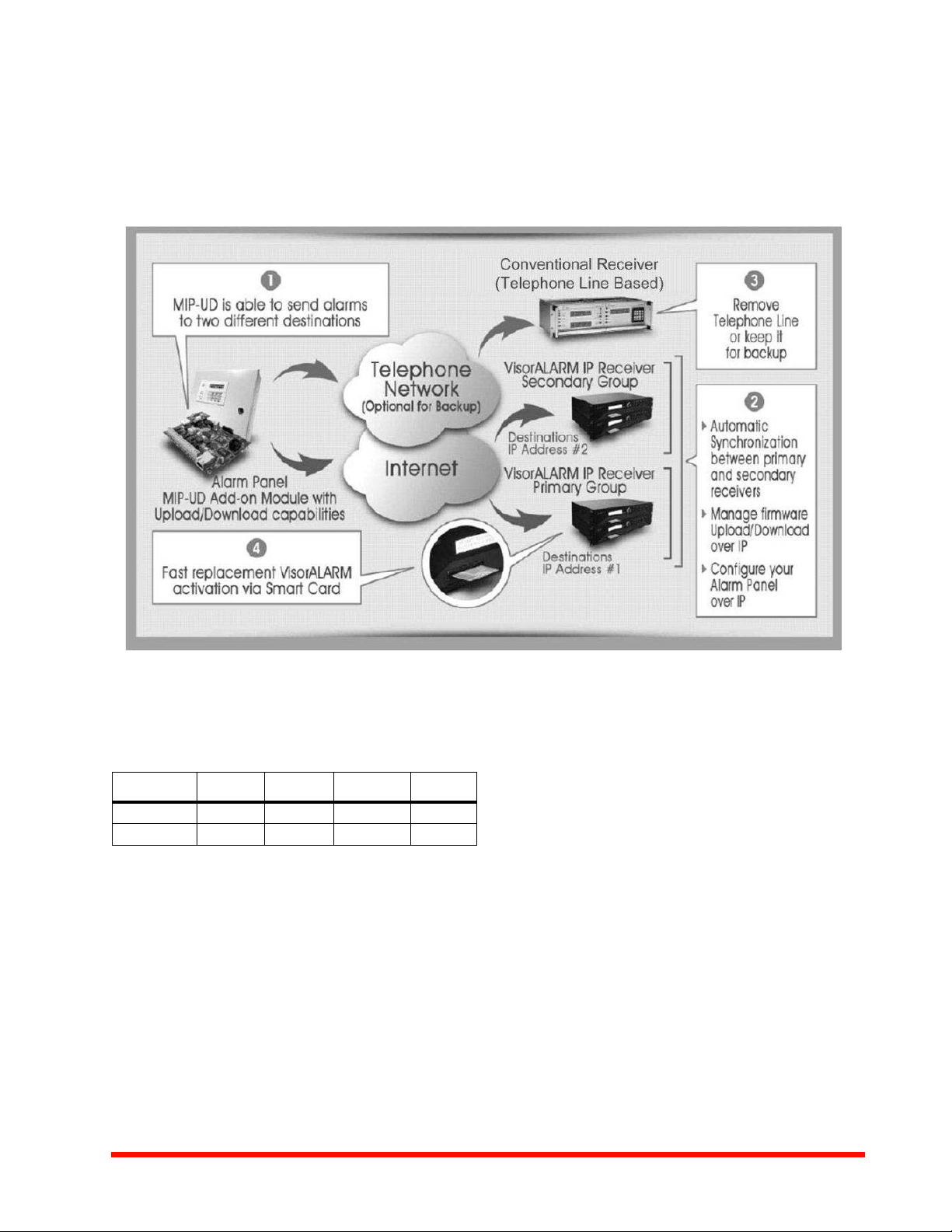
System Architecture/Operating Theory
• The MIP-2/UD is connected to an Internet router.
• The telephone line, instead of going directly to the panel, is
now connected to the MIP-2/UD and from the MIP UD it is
then connected to the panel.
• The MIP-2/UD monitors the status of the Internet connection with the receiver and decides which network to use to
transmit the alarms received from the panel.
• At the central station side, a conventional receiver will still
be used to receive alarms transmitted through the telephone line. If the Internet connection is available, the
alarms will be sent to a VisorALARM receiver at the monitoring station.
• The MIP-2/UD keeps constant communication with the
panel to implement a real time line supervision functionality.
Specifications
POWER
Nominal voltage: 10 VDC to 24 VDC
Max current:
Idle Alarm Transient UD
A 12Vdc 160mA 180mA 400mA 330mA
A 24Vdc 90mA 104mA 200mA 160mA
LAN PORT
Connector: RJ45 female.
Speed: 10 Mbps.
P r o t o c o l s : UD P, I P, S R P, D H C P, A E S .
TELNET, ETHERNET BLUEBOK
INPUTS AND OUTPUTS:
Output 1: 500 mA. Dry Contact N.O. or N.C. 2A Max.
Output 2: 500 mA. WatchDog.
Inputs: 2.
CONSOLE:
Asynchronous: 9600 bps, 8 bits, without parity, 1 stop bit.
Password protected.
Telephone: Connection through TO-AP using a telephone key
pad.
TELNET: Password protected.
Dimensions and Weight
5.5L x 3.62W x 1.42H inches
Weight: 150 gr / 3 ounces
Temperature and Humidity Ranges
This system meets NFPA requirements for operation at 0 49°C/32 - 120°F and at a relative humidity 93% ± 2% RH (noncondensing) at 32°C ± 2°C (90°F ± 3°F). However, the useful
life of the system's standby batteries and the electronic components may be adversely affected by extreme temperature
ranges and humidity. Therefore, it is recommended that this
system and its peripherals be installed in an environment with
a normal room temperature of 15 - 27°C/60 - 80°F.
Page 2 of 4 — DH-60768:A • 3/11/2013 www.honeywell.com
Page 3

Agency Listings and Approvals
In some cases, certain modules or applications may not be
listed by certain approval agencies, or listing may be process.
Consult factory for latest listing status.
BURGLAR
• UL1023: Household Burglar Alarm System-Units.
• UL1076: Proprietary Burglar Alarm Units and Systems.
• UL1610: Central Station Burglar Alarm Units.
• ULC C1023-1974: Household Burglar Alarm System-Units.
• ULC/ORD=C1076-M1986: Proprietary Burglar Alarm Units
and Systems.
• CAN/ULC S304-M88: Central and Monitoring Station Burglar Alarm Units.
Ordering Information
MIP-2: IP Communicator. Includes configuration software and
manual.
MIP-2UD: IP Communicator with upload/download capability
(2UD modem daughter board). Includes configuration software
and manual.
IPENC: External mounting enclosure consisting of mounting
bracket IPBRKT, and screws. Enclosure must be "close-nipple" to a panel. (Red)
IPSPLT: Y adapter option to allow connection of both panel
dialer outputs to one cable input to MIP-2/UD.
ALMSC-119: Serial programming cable.
HP300ULX: Honeywell Power Products UL 1481-listed auxil-
iary power supply. Enclosure must be "close-nipple" to a panel
via conduit. Requires IPBRKT purchased separately.
IPBRKT: Mounting bracket.
www.honeywell.com DH-60768:A • 3/11/2013 — Page 3 of 4
Page 4

This document is not intended to be used for installation purposes. We try to keep our product information up-to-date and accurate. We cannot cover all specific
applications or anticipate all requirements. All specifications are subject to change without notice.
©2013 by Honeywell International Inc. All rights reserved. Unauthorized use of this document is strictly prohibited.
Automation and Control Solutions
Honeywell
12 Clintonville Road 1(877) HPP-POWR
Northford, CT 06472-1610 hpp.techserv@honeywell.com
www.honeywellpower.com
DH-60768:A
April 2013
Made in the U.S.A.
® U.S. Registered Trademark
© 2013 Honeywell International Inc.
Page 4 of 4
 Loading...