

32-00015-04
U2-S Model Combination Viewing
WARNING
WARNINGWARNING
AVERTISSEMENT
AVERTISSEMENT
WARNUNG
ATENÇÃO
Head and Signal Processor
USER MANUAL
GENERAL INFORMATION
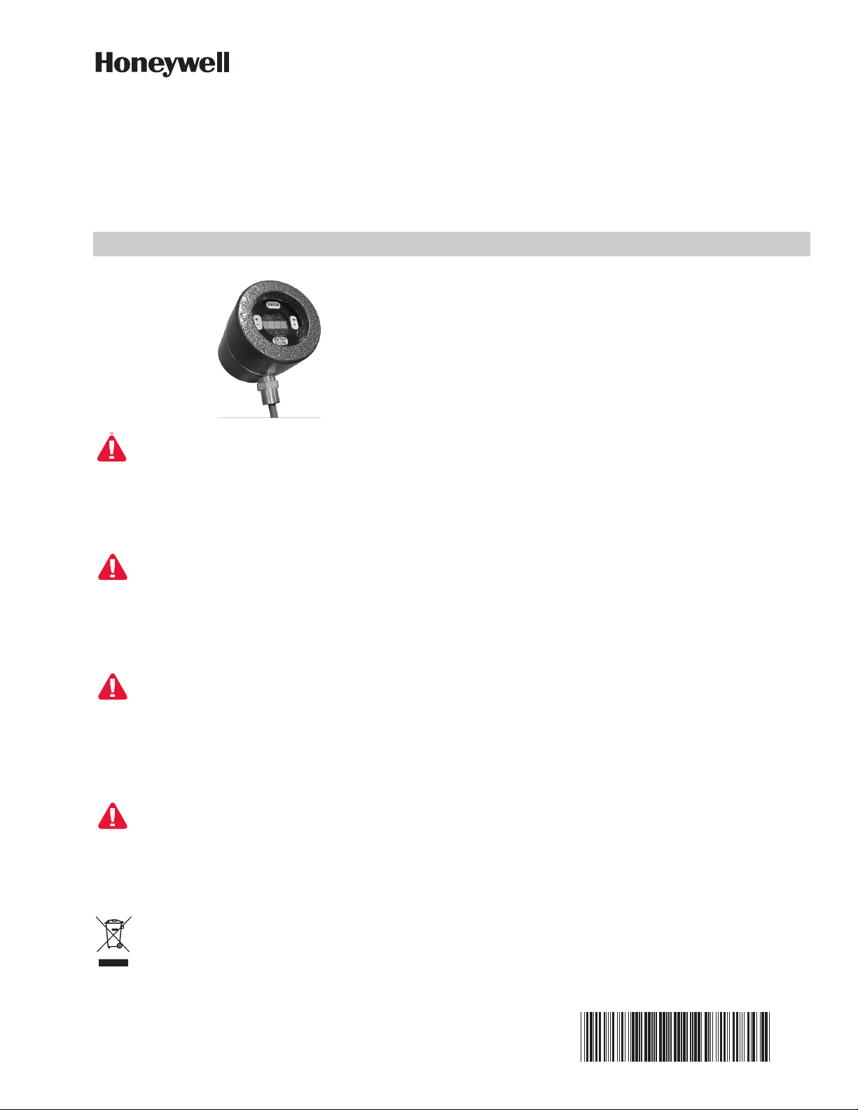
The Honeywell U2-101xS series model is a viewing head
and signal processor in a single enclosure intended for
use with a burner control system in Industrial Flame
Monitoring applications. There are several options
available (see Table 1 on page 2). Each model includes
one, two, or all three sensors, and can be ordered with
quick disconnect (non-PF Models DIV2,ZN2) or pigtail
external connection method (PF Models DIV1,ZN1).
Each sensor operates independently from another,
allowing adjustment of each sensor.
Read the instructions before use. This control shall be
installed in accordance with the rules in force. Additional
versions of this manual are available online at
https://customer.honeywell.com/enUS/Pages/default.aspx in Canadian French, Portuguese,
and German. Please enter 32-00015 in the search box
and choose Technical Literature from the drop-down
box.
Lire les instructions avant l'utilisation. Cette commande
doit être installée conformément aux lois en vigueur. Des
versions supplémentaires de ce manuel sont disponibles
enligne à https://customer.honeywell.com/enUS/Pages/default.aspx en français du Canada, en
portugais et en allemand. Veuillez inscrire 32-00015 dans
le casier de recherche et choisissez Documentation
technique à partir du menu déroulant.
Lesen Sie vor der Verwendung die Anweisung. Diese
Konsole muss entsprechend den geltenden Vorschriften
installiert werden. Zusätzliche Versionen dieses
Handbuchs sind online unter
https://customer.honeywell.com/enUS/Pages/default.aspx in Frankokanadisch,
Portugiesisch und Deutsch verfügbar. Bitte geben Sie im
Suchfeld 32-00015 ein und wählen Sie Fachliteratur im
Drop-Down Menü aus
IMPORTANT
Flame monitoring systems are safety systems.
Please read this manual carefully and completely
before installation and before attempting adjustments.
Only qualified personnel familiar with Flame
Safety System should carry out installation and
configuration.
U2 is certified to be used in prescribed manner.
Any modification or inappropriate installation or
operation may result in unsafe operation and will
void implied or expressed warranty.
Sensors
The UV tube detector has a peak response at 210 nm.
The IR solid state sensor has a peak response at 1400 nm.
The UV solid state sensor has a peak response at 310 nm.
Cabling Options (Sold Separately)
ASYU2S - Quick Disconnect (non-PF) models molded
connector cable assembly with 50 foot of C22S cable.
Leia as instruções antes de usar. Esse controle tem que
ser instalado de acordo com as normas vigentes. Outras
versões desse manual estão disponíveis online em
https://customer.honeywell.com/enUS/Pages/default.aspx em francês do Canadá, português
e alemão. Insira 32-00015 em cada caixa e selecione
Literatura Técnica na caixa suspensa.
Disposal and Recycling
Waste electrical products should not be disposed
of with general waste. Please recycle where these
facilities exist. Check with your local authority for
recycling advice.
Contents
GENERAL INFORMATION ............................................... 1
SPECIFICATIONS ............................................................ 2
INSTALLATION ................................................................. 3
OPERATION ..................................................................... 6
U2 MENU PARAMETER SETTINGS ................................ 7
TROUBLESHOOTING ...................................................... 10
SAFETY MANUAL ............................................................ 13
Safety Function of the U2-S Model .............................. 14
Proof Test Procedure ................................................... 14
Proof Test Interval ........................................................ 14
Product Decommissioning ........................................... 15
U2-S MODEL COMBINATION VIEWING HEAD AND SIGNAL PROCESSOR
WARNING
WARNINGWARNING
WARNING
WARNINGWARNING
ASYU2S-100 - Quick Disconnect (non-PF) models molded
connector cable assembly with 100 foot of C22S cable.
ASYU2S-200 - Quick Disconnect (non-PF) models molded
connector cable assembly with 200 foot of C22S cable.
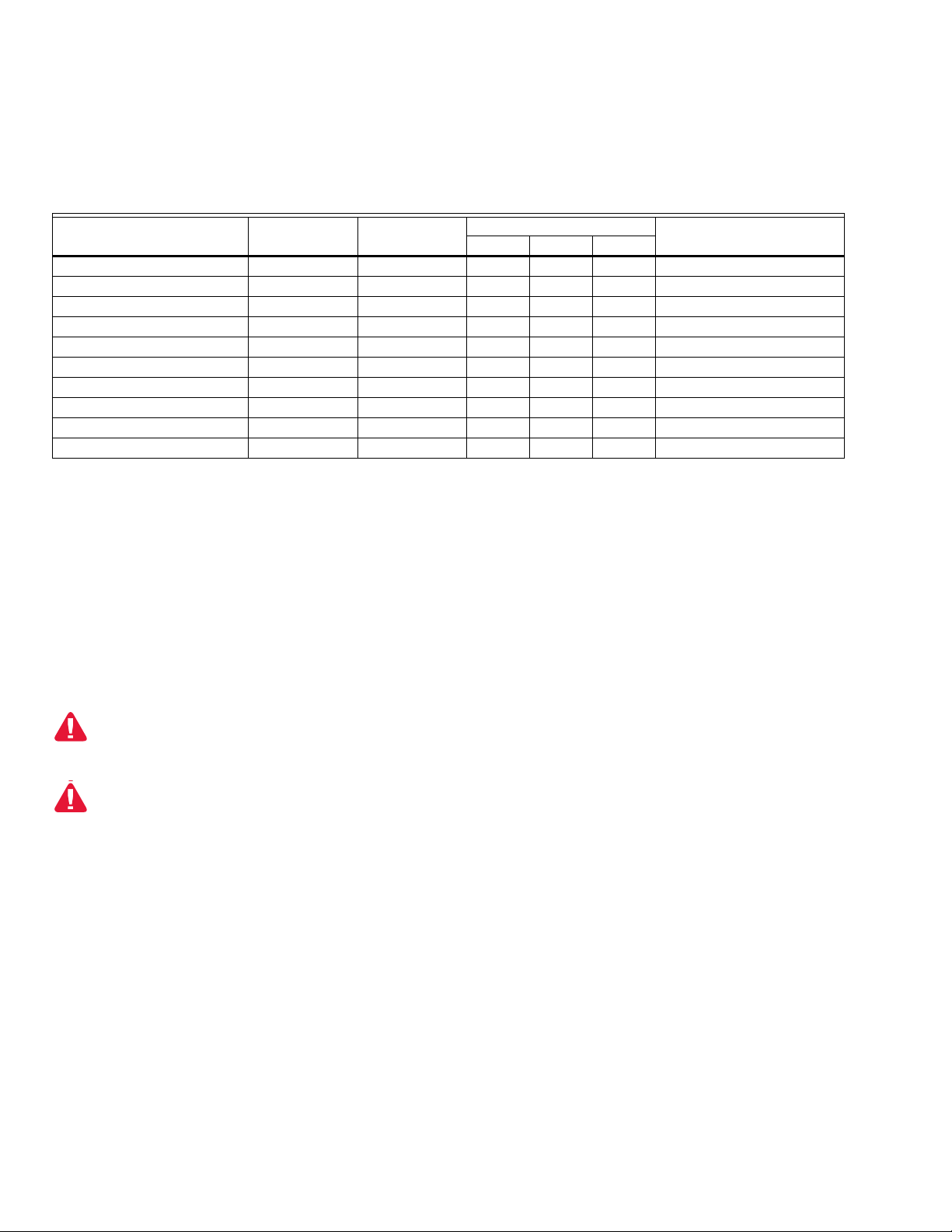
Table 1. Models and Associated Features.
Quick
Model
U2-1010S X X X X All Fuels
U2-1010S-PF X X X X All Fuels
U2-1010S-PF-050* X X X X All Fuels
U2-1010S-PF-100 X X X X All Fuels
U2-1012S X X Oil and Coal
U2-1012S-PF X X Oil and Coal
U2-1016S X X Gas and Light Oils
U2-1016S-PF X X Gas and Light Oils
U2-1018S X X X All Fuels
U2-1018S-PF X X X All Fuels
* The U2-1010S-PF-050 has a 50-ft (15m) pigtail and the U2-1010S-PF-100 has a 100-ft (30m) pigtail.
Connector
Pipe Fit
Connection
SPECIFICATIONS
Input Power Supply: 22-26 VDC, 120 mA max (approxi-
mately 3.5 watts)
Remote Communication: 2 wire RS485 compatible with
Modbus RTU protocol.
Flame And Fault Relay Contact Ratings:
1 A, 30 VDC (Resistive).
Maximum load current of 1A must be de-rated at tem-
peratures higher than 50C ambient according to 1%/C,
or 10mA/C. For example, the maximum current at
70C = 1A – (20C x 10mA) = 0.8A.
Do not apply more than 30VDC to flame relay or
self check relay.
The U2 requires the use of an isolated 24VDC
SELV (Safety Extra Low Voltage) power supply.
User Selectable Analog Output: 0-20 mA and 4-20 mA;
500 Ohm Load Max
File Select Input logic high: 21VDC min
File Select Input logic low: 16VDC max
User Interface: Capacitive TouchWheel with LED Display
Ambient temperature: -40 to 70 ºC (-40 to 158 ºF)
Enclosure: IP66
Weight: 2.8 kg (6.1 lbs)
Physical Dimensions: Diameter: 11.7 cm (4.6 inches)
Length: 15.5 cm (6.1 inches)
Finish: Silicone free powder coated
ASYU2S-300 - Quick Disconnect (non-PF) models molded
connector cable assembly with 300 foot of C22S cable.
C22S - Raw shielded 12 conductor, 22g, ITC, CIC
approved. Order by the foot.
Sensor Type
Typical FuelsUVTron IR UVSS
Mounting/Process Connection: 1” NPT female
Pipe Fit Models (PF version): 3/4” NPT
Fuses: Automatically resettable for power source and
Flame Relay.
Maximum furnace back pressure: 35 Kg/Cm2 (500 PSI)
Selectable Flame Failure Response Time (FFRT):
1, 2, 3 seconds, Error= +0.0sec, -0.5sec.
Internal Temperature Indication: Degrees C or F in dis-
play menu of U2, or available at Modbus register
40019.
Self-Checking
Internal electronic self checking is performed once per
second, to verify that system is operating properly. If
self check detects an error, the flame relay, and self
check relays will open, and the device will display "lockout". This lockout may only be cleared by manual entry
reset at the U2 Touchwheel interface.
Approvals:
Quick disconnect type
General
FM, CSA, CE (EN298), and EAC
Hazardous Location
CSA
CLASS I, DIVISION 2, GROUPS A, B, C, D
CLASS II, DIVISION 1, GROUPS E, F, G
CLASS III DIVISION 1 T5
Ex nA nC IIC T5 Gc Ex tb IIIC T85°C Db
CLASS I, ZONE 2, AEx nA nC IIC T5 Gc
ZONE 21 AEx tb IIIC T85°C Db
IECEx SIR 15.0068X Ex nA nC IIC T5 Gc
Ex tb IIIC T85°C Db IP66
SIRA 15ATEX4193X Ex nA nC IIC T5 Gc
Ex tb IIIC T85°C Dc IP66
32-00015—04 2
U2-S MODEL COMBINATION VIEWING HEAD AND SIGNAL PROCESSOR
CAUTION
CAUTION
!
CAUTION
CAUTION
!
CAUTION
CAUTION
!
WARNING
WARNINGWARNING
WARNING
WARNINGWARNING
PF version
General
FM, CSA, CE (EN298), and EAC
Hazardous Location
CSA
CLASS I, DIVISION 1, GROUPS A, B, C, D
CLASS II, DIVISION 1, GROUPS E, F, G
CLASS III DIVISION 1 T6
Ex d IIC T6 Gb Ex tb IIIC T85°C Db
CLASS I, ZONE 1, AEx d IIC T5 Gb
ZONE 21 AEx tb IIIC T85°C Db
IECEx SIR 15.0068X Ex db IIC T6 Gb
Ex tb IIIC T85°C Db IP66
SIRA 15ATEX1192X Ex db IIC T6 Gb
Ex tb IIIC T85°C Db IP66
Possible Equipment Damage
The aluminum surface of the U2 may store an
electrostatic charge and become a source of
ignition in applications with a low (<30%) relative
humidity. Cleaning the surface should only be
done with a damp cloth.
Do not expose to acetone, gasoline, hexane, or
ethyl acetate. label is not approved for these
chemicals.
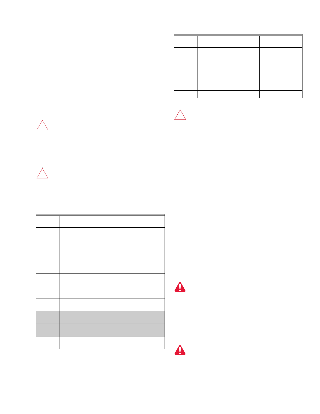
Non-PF/
Color Function Connection
9-Tan File Select Output, 0 or +24V
output. Feedback for system
controlling file input select.
10-White +RS485 Modbus To Modbus +
11-Drain Cable Overall Shield To Earth Ground
12-Brown -RS485 Modbus To Modbus -
*Note - pink wire unused, leave unconnected.
Check wiring before applying power to the
system to make sure it is in accordance with the
wiring chart. Incorrect wiring may result in
unsafe operation or damage to U2.
NOTES:
1. For remote configuration and monitoring, refer
to Honeywell manuals for FlameTool for PC
(32-00001-01) and HMI S7999 Panel (3200003-01).
2. A total of eight parameter files are available.
Files 2 through 7 may be accessed using Flametools, and configured using Modbus register 40093.
To burner control
system. 0V = File
Select Input is low, or
+24V if FileSelect
Input is high.
Wiring
See “Typical Installation Diagram.” on page 12.
Non-PF/
Color Function Connection
1-Red Power Supply +24 VDC
Connect to 22-26 VDC
2-Purple File Select Input, 0 or 1 To control output.
3-Orange mA output (+) To current meter
4-Blue mA output (-) To current meter
5-Black Power Supply Return (-) or 0
VDC
6-Yellow Flame Relay (NO)
(power in)
7-Green Fault Relay (NO) (fault output) To fault monitoring of
8-Grey Flame Relay (NO) (safety
output)
To power supply
positive terminal
>21V input = file 1,
<16V = active file
defined at Modbus
register
40093(default 0).
positive
negative
To Power Supply
negative terminal.
To flame/fault relay
power source
burner control system
To burner control
system
INSTALLATION
See “Typical Installation Diagram.” on page 12.
Installation should be carried out by a qualified engineer
and should meet all local standards and safety
requirements.
Hazardous location installations require the use of
ITC/CIC approved cable installed in cable tray for non-PF
models, and in metal conduit for -PF models. The cable
installation must conform to the latest revision of the
National Electrical Code, or Canadian Electrical Code for
Class I, Division 2 (non-PF models), or for Class I, Division
1 (-PF models).
Approved CLI, DIV1 conduit seal must be installed
at PF model enclosure fitting for CLI, DIV1
hazardous location use.
Non-PF models must be secured as follows: hand-tighten
the connector at viewing head until it can be turned no
more. Continue tightening the connector an additional
180 degrees using pliers, or similar tool. Verify that
connector cannot be loosened by hand.
Over-tightening the connector can damage the
connector or housing.
Damage will void warranty and hazardous location
approvals. Do not exceed 180 degrees of further
rotation after hand tightening!
3 32-00015—04
U2-S MODEL COMBINATION VIEWING HEAD AND SIGNAL PROCESSOR
WARNING
WARNINGWARNING
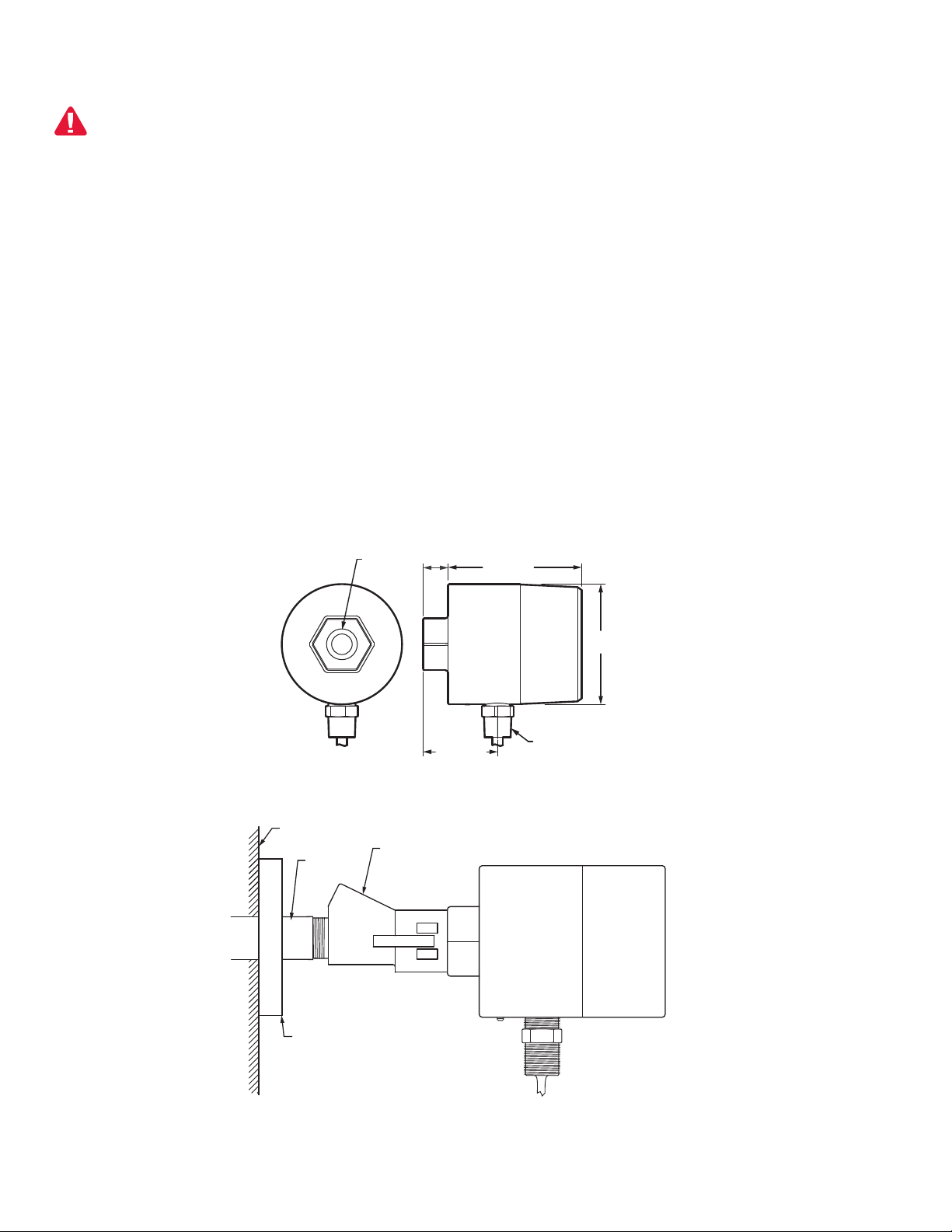
3/4 (19) NPT
CONNECTION
2-29/32 (73)
1(25)
1 (25) NPT
CONNECTION
5-3/32 (130)
4-19/32
(118)
M34431
R-518-CL12-PG
PURGE AIR COUPLER
AND R-518-PT12
INSULATING LOCKING
COUPLER ADAPTER
BURNER FRONT PLATE
OR WINDOWBOX
M33628
1 (25)
NPTF PIPE
FLANGE
(OPTIONAL)
1. Ensure location provides clear view of the flame
under all operating conditions.
EXPLOSION HAZARD
DO NOT DISCONNECT WHILE CIRCUIT IS LIVE
UNLESS AREA IS KNOWN TO BE
NONHAZARDOUS.
Substitution of components may impair suitability
for class i, division 2.
2. If the burner is provided with a pipe mount, use a bell
type reducer to 1" NPT (M).
3. When using purge/cooling air, make sure hoses are
electrically isolated from the Earth to prevent multiple ground loops.
4. Depending upon the application, purge/cooling air
pressure and flow will be different. As it is easier to
The U2-S model viewing port is designed for interface to a
1" NPT (M) fitting. The viewing head can be mounted in
any orientation, any angle, upward or downwards.
It is recommended that earth ground is applied at the
labeled earth ground screw connection on the housing. It
is recommended the drain wire be connected to earth at
power supply.
To reduce noise interference from ignition transformer or
other high voltage sources, make sure all high voltage
cables are in good condition and are at least 300 mm (12")
away from U2 wiring.
Location/Mounting on Burner
Honeywell can provide mounting accessories such as a
swivel mount, heat/electrical insulator, quick mechanical
measure pressure than flow, ensure that the
entrance to air connection is a minimum of 25 mm
WC (1" wc) above back pressure at all the time, from
minimum to maximum load.
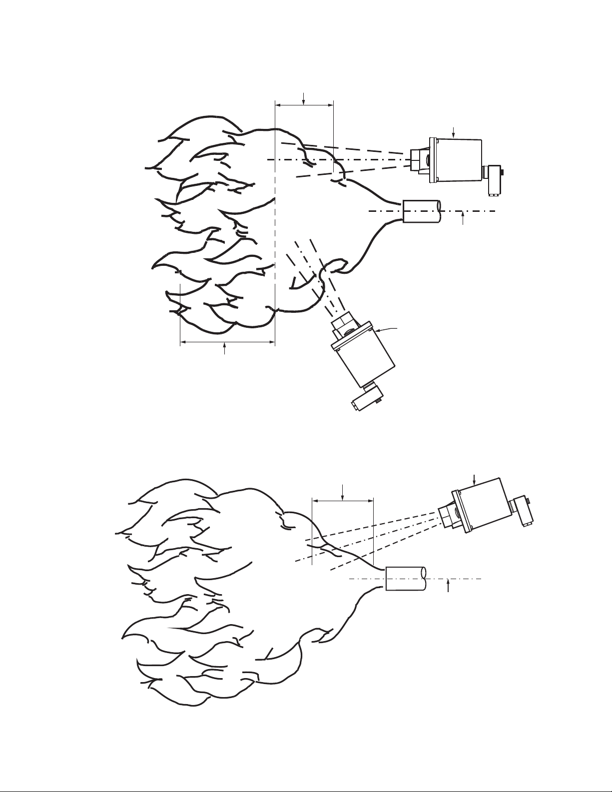
5. IMPORTANT!
FLAME DISCRIMINATION
In multi-burner applications, it is important to sight
for high frequency, high radiation intensity zone of
the target flame, while sighting the low frequency,
low radiation intensity zone of the background flame
see Fig. 3 for IR, or Fig. 4 for UV for an example. This
allows for filter, gain, and threshold settings to properly discriminate or recognize the target flame while
rejecting background flame.
6. Where practical, use a swivel mount to allow for
adjustments to optimize the flame viewing location.
disconnect, high pressure isolation unit, etc. Check with
your sales representative for your application.
Fig. 1. Dimensional drawings.
32-00015—04 4
Fig. 2. Typical mounting example.
U2-S MODEL COMBINATION VIEWING HEAD AND SIGNAL PROCESSOR
UV VIEWING
HEAD SIGHTED
ON UV ZONE
BURNER NOZZLE
CENTERLINE
UV RADIATION
ZONE
M33286B
HIGH FREQUENCY
FLICKER ZONE
DETECTOR IN GOOD
SIGHTING POSITION
(PARALLEL SIGHTING)
BURNER NOZZLE
CENTERLINE
LOW FREQUENCY
FLICKER ZONE
Fig. 3. IR viewing head location.
DETECTOR IN POOR
SIGHTING POSITION
M33285B
Fig. 4. UV viewing head location.
5 32-00015—04
U2-S MODEL COMBINATION VIEWING HEAD AND SIGNAL PROCESSOR
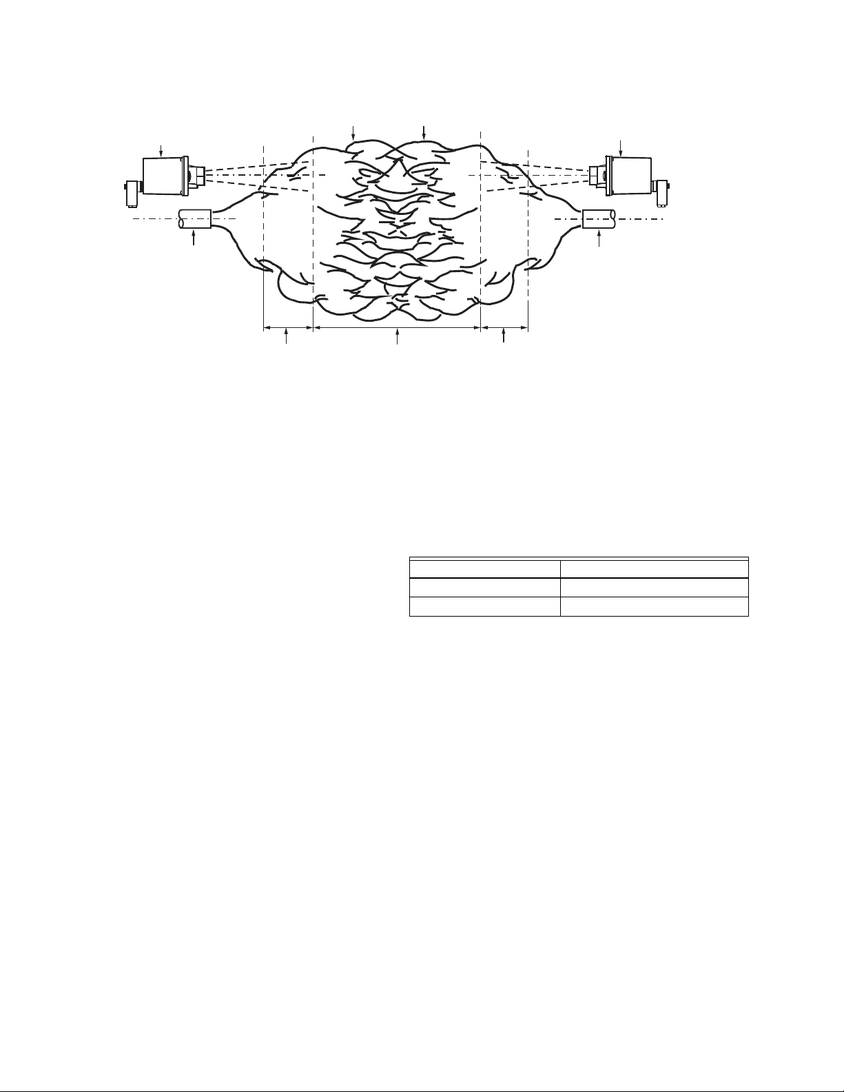
VIEWING HEAD
BURNER NOZZLE
NO. 1
NO. 1 FLAME
ENVELOPE
NO. 2 FLAME
ENVELOPE
VIEWING HEAD
BURNER
NOZZLE NO. 2
HIGH FREQUENCY
IR ZONE
LOW FREQUENCY
ZONE (LESS THAN
36HZ)
HIGH FREQUENCY
IR ZONE
M33287B
Fig. 5. Sighting opposed fired burners.
Mounting Accessories
1. Cable assemblies for quick disconnect models are
listed below. All are ITC/CIC approved, and meet
IP67 at connector when properly installed.
• ASYU2S molded connector with 50 foot cable.
• ASYU2S-100 molded connector with 100 foot
cable.
• ASYU2-200 molded connector with 200 foot
cable.
• ASYU2-300 molded connector with 300 foot
cable.
2. Fiber Optic System - The U2 models are compatible
with the Honeywell FASA Glass or Quartz fiber optic
extension. Refer to Honeywell manual 69-2683
3. U2-S supports Modbus protocol. The system can be
monitored using user's hardware and software
and/or Honeywell FlameTool for PC or Honeywell
FlameTool for Panel (S7999). For detail refer to manual 32-00001 and 32-00003.
4. There are several mounting accessories available
from Honeywell. Please check with your sales person
for detail.
a. R-518-PT12 (Ultem Iso PT Adapter)
b. R-518-PT12L (Ultem Iso PT Adapter with lens)
c. R-518-CL12-PG (Purge Air Coupler 1" NPTM &
1/2" NPTF)
d. M-701-2 (Swivel Mount)
e. R-518-CL12-HTG (Locking Coupler).
OPERATION
Available sensors continuously convert flame radiation to
a magnitude displayed on the U2 display. The displayed
value described further as "flamecount" is the sum of all
active sensor readings.
If flame count is greater than the flame on setpoint for
longer than the time delay, a flame on condition is realized
and the flame relay contacts are closed. The flame relay
contacts remain closed until the flame count falls below
the flame off setpoint for longer than the flame failure
response time, at which a flame off condition is realized
and the flame relay contacts are opened. Periodic self
check performs fault detection, and if a fault is detected,
both the flame relay and self check relay contacts are
opened.
While File Input Select is low, file parameters defined at
Modbus register 40093 are used to determine flame relay
state. While file input select is high (+24V), file 1 parameter
settings are used to determine flame relay state.
File Select Output provides feedback to indicate the state
of the file input select. See chart below:
File Input Select Value File Select Output Value
0V 0V
24V 24V
There are several parameter adjustments that permit
configuration of each sensor. .
A touch wheel located at the back of the viewing head
provides access to parameters for adjustment and
configuration. The configuration menu is simple and easy
to follow. Full character, 4-digit, scrolling LED displays are
visible in the dark or sunlight. Individual sensor LEDs
(model dependent 1, 2, or 3 total located below the
display) flash to indicate the output of each sensor (green
= UVTron, Blue = SSUV, Red = IR). The upper right green
self-check LED provides indication, and status of the self
check. The upper left red "Flame On" LED provides status
of the flame relay.
NOTE: The number of LEDs are model dependent.
The touch wheel is designed like an iPod™ to allow for slow
or fast changes by moving a finger slower or faster around
the back glass. Alternatively, the user may tap ← (-) or →
(+) to make changes. Swirl finger at touchwheel > 360
degrees and release to enter the menu. Tap
ENTER/STORE to store selected data. Tap BACK to return
to the previous menu. Exiting all of the menus will display
the current flame count.
NOTE: Only the pertinent menu will be displayed. For
example, for UVtron only sensor (U2-1016S and
U2-1016S-PF), only UVTron gain will be displayed. UVSS and IR gain will not be visible.
32-00015—04 6

U2-S MODEL COMBINATION VIEWING HEAD AND SIGNAL PROCESSOR
CAUTION
CAUTION
!
Display, as seen by the user, is shown in BOLD RED in the list
below as it appears in sequence.
U2 MENU PARAMETER SETTINGS
If the display shows "9999" while in operation, it
indicates flamecount has exceeded maximum
range of device. Reduce appropriate sensor
gain(s) so that Flame count is about 1.5 to 3
times Flame OFF threshold settings. If
unsuccessful, orificing or increased sight pipe
length may be required.
Gain UVTron
GTXX - Displays the current UVTRON tube sensor gain
(adjustable 0-99). The default value is 32.
Gain SSUV
GÛXX - Displays the current solid state UV sensor gain
(adjustable 0-99). The default value is 75. Adjusting the
gain too high may result in lockout due to saturation of the
sensor.
Flicker Filter Setting for SSUV
FÛ0X - Displays the current solid state UV flicker filter
setting (adjustable 0-9). The default value is 3.
Gain IR
GIXX - Displays the current IR sensor gain (adjustable 0-
99). The default value is 75. Adjusting the gain too high
may result in lockout due to saturation of the sensor.
Flicker Filter Setting for IR
FI0X - Displays the current IR sensor flicker filter setting
(adjustable 0-9). The default value is 3.
Flicker settings indicated below apply to SSUV and IR.
These are high pass filter setting:
Setting HZ Setting HZ Setting HZ
0 9 4 52 8 215
1 16 5 75 9 300
2246 100
3337 155
Gain MA OUT
GMXX - Displays the current multiplier for analog output
(adjustable 0-99). The default value is 30, and will result in
approximately 12mA analog out at 1700 flamecount, and
20mA at 3425 counts. The ma gain setting allows for
scaling of the analog output value proportional to the
flamecount at full load. For example, increasing the gain,
increases the analog output for a given flamecount.
Adjusting the MA gain does not alter gain settings of
UVTron, SSUV, or IR. After completing flame setpoint
configuration, adjustment to the MA gain may be used to
set MA output at full system load.
Flame On Threshold Setting
Displays the current Flame On threshold settings. It is
important to note that flame count must reach this
threshold in order for the flame relay to energize. After the
flame relay is energized, the flame count may drop below
Flame ON threshold but must remain above Flame Off
threshold (refer to FFRT below). Range is 51- 3425 flame
count.
NOTE: The Flame ON threshold setting must be 1 digit
above Flame OFF setting.
Flame OFF Threshold Setting
Displays the current Flame OFF threshold settings. Flame
count must remain above Flame Off threshold setting
otherwise flame relay will be de-energized after Flame
Failure response time has expired. Range is 50- 3424
flame count.
NOTE: The Flame Off threshold setting must be 1 digit
below Flame On setting.
Flame Failure Response Time (FFRT)
RT0X - Displays the current Flame Failure response time in
seconds. Flamecount must remain above Flame Off
threshold setting otherwise the flame relay will be deenergized after Flame failure response time has expired.
FFRT selection is 1, 2 or 3 seconds. Default setting is 1
second.
IMPORTANT
The FFRT must be set to 1 second, to meet requirements defined in European Standard EN298,
unless the application standard allows for longer
response time. Care must be used to ensure that
the overall response time of the system is acceptable for safe operation.
Flame On Time Delay
TD0X - Displays the current Flame On time delay in
seconds. The flame relay will be energized after the
flamecount has remained above the flame ON threshold,
and the time delay has elapsed. This feature is useful in
applications where flames from other sources are
temporarily present in target area, such as grate fired
boilers. Selection is 0,1, 2 or 3.
NOTE: The time delay also reduces Trial for Ignition by
the set time. Default setting is 3 seconds.
File Selection
*F0X - The U2 is able to store up to 8 different file
(configurations) (file0 - file7). Files are used to store
device settings for different fuels or applications.
Parameters that are stored in each file include Flame On
Setpoint, Flame Off Setpoint, Flame Failure Response
Time, Time Delay, UVT Gain, SSUV Gain, IR Gain, SSUV
Filter, IR Filter, mA gain, and Panel timeout.
Modifying file parameters
Press ENTER at menu location FILE, and select file
number using the touchwheel. Press enter when desired
file number is reached. The 4 digit display will flash
7 32-00015—04
U2-S MODEL COMBINATION VIEWING HEAD AND SIGNAL PROCESSOR
WARNING
WARNINGWARNING
WARNING
WARNINGWARNING
decimal points to indicate file other that 0 is being
modified. Change menu parameters as desired.
IMPORTANT! Menu selections will only affect the currently
selected file.
NOTE: The U2 touch wheel interface allows access to all
eight files for configuration; however, the active
file cannot be changed at the U2 interface. It can
only be changed at the "File Select" wired input or
through Modbus communication. Only two files,
"0" and "1", may be automatically activated by
changing the voltage input to the "File Select"
wire (purple). When the file select line is power
grounded, the file selection = "0", when connected
to 24 VDC File select #1 is automatically activated.
NOTE: File selection for "0" may be changed, by modify-
ing the modbus register location 40093. Default
value is 0, and may be changed to 0 through 7.
When using file select input (purple) to control
parameter selection for different fuels, control
system must monitor file select output (tan) to
confirm U2S is using the correct file parameters. If
only one file parameter is used, set file 0 and file 1
settings to identical values, and connect file input
select to ground.
Panel Lock and Time Out.
Tapping the ENTER/STORE button when PANEL appears
on the menu screen will provide access to two sub-menus.
Panel Lock
The Panel Lock sub-menu enables a security feature that
locks the U2 interface preventing any parameter
modifications.
A factory default 4-digit access code is required to enable
panel lock. This code is only available from the factory.
Once enabled, the same code will be required to modify
parameters from the touch-wheel interface. Any attempt
to make changes will generate the message, "Panel
Locked Enter Code". The display will show "Bad" upon
entry of an incorrect access code. Additionally, a user may
select a unique lock code through Modbus, this procedure
is only available from the factory.
If the password is forgotten or lost, the user must contact
the factory for assistance with unlocking the panel.
Panel Timeout
The Time Out sub-menu allows for adjustment to a
secondary safety feature that locks the U2 interface
preventing accidental parameter modifications. This
setting may be adjusted from 0-9999 minutes. After this
time expires, with no touchwheel activity, any attempt to
access the menu will generate the message, "KEY
DISABLED ENTER 1234", simply enter "1234" as
prompted by the display. The Panel Time Out is by default
10 minutes, and is disabled with a setting of 0.
Communication
The U2-S products support 2 wire Modbus RTU
communication as slave devices. Default address is 0, and
must be changed prior to use. The communications
submenus allow adjustment of settings. See
communications sub menus, and Fig. 1 for details. Default
communication settings are:
— 9600 baud
— 8 data bits
—no parity
—1 stop bit
Note that some registers are read only.
Do not write to registers not defined in the list
below.
Register
Address Register Description
40001 FLAMECOUNT R
40003 FLAME ON SETPOINT(50-3425) R/W
40005 FLAME OFF SETPOINT(51-3425) R/W
40007 MA GAIN(0-99) R/W
40011 IR FILTER(0-9) R/W
40012 UVTUBE GAIN(0-99) R/W
40015 SSUV FILTER(0-9) R/W
40016 SSUV GAIN(0-99) R/W
40019 TEMPERATURE R
40021 TIMEDELAY(0-3) R/W
40022 FFRT(1-3) R/W
40085 BAUD(24-1152) R/W
40086 PARITY(0-2) R/W
40087 COMM ADDRESS(0-247) R/W
40089 KEY TIMEOUT(0-9999) R/W
40092 NUMFILES(1-8) R/W
40093 ACTIVE FILE(0-7) R/W
40095 UVTUBE FLAMECOUNT R
40096 IR FL AMECOUNT R
40097 SSUV FLAMECOUNT R
401x0 FLAMEON SETPOINT x = file 0-7 R/W
401x1 FLAMEOFF SETPOINT x = file 0-7 R/W
401x2 FFRT x = file 0-7 R/W
401x3 TIMEDELAY x = file 0-7 R/W
401x4 UVTGAIN x = file 0-7 R/W
401x5 UVSSGAIN x= file 0-7 R/W
401x6 UVSSFILT x = file 0-7 R/W
401x7 IRFILT x = file 0-7 R/W
401x8 IRGAIN x = file 0-7 R/W
401x9 MA GAIN x = file 0-7 R/W
40182 MODBUSLOCK R/W
40000 -
40300
Other registers unlisted in this
range are special use. DO NOT
WRITE.
Read
Write
NA
32-00015—04 8

U2-S MODEL COMBINATION VIEWING HEAD AND SIGNAL PROCESSOR
WARNING
WARNINGWARNING
Address
For applications with many flamescanners on single
modbus loop, it is recommended to start with address 11
for burner #1, 21 for burner #2 and so on.
Baud
Speed of Modbus communications (2400, 4800, 9600,
19200). The default baud is 9600.
Parity
Select Modbus checking method (NONE, ODD, or EVEN).
The default parity is NONE.
RS485
Sets Modbus registers to either READ ONLY or read and
writable (WRITE OK). Default is "Read and Write".
IMPORTANT!
Modbus registers should be set to read only
through the menu, or locked using modbus register 40182 after system commissioning to prevent
unintended writes to critical parameters. Modbus
register lock requires code from factory, contact
your sales representative for details.
0-20 mA OR 4-20 mA
Sets the current output to either 0-20mA or 4-20mA. The
4-20mA output is the default setting.
Auto Gain
NOTE: Auto Gain and Auto Filter only adjust solid state
UV, and IR sensors. It will not adjust UV tube gain,
and is non-functional in U2-1016 or U2-1016-PF
models.
This menu selection automatically sets the gain for the
SSUV and IR sensors necessary to generate a total flame
count of approximately 1200. Desired sensors must be
turned on (gain of at least 1) before auto gain is selected.
Auto Filter
This menu selection automatically sets the optimum filter
for the SSUV and IR sensors. It should only be performed
after the AUTO GAIN routine.
NOTE: While using the Auto Gain and Auto Filter modes,
the system will be adjusting to the firing conditions at the time of implementation. This condition should be carefully selected to ensure
discrimination through complete load changes
from minimum to maximum and from cold
burner/boiler startup to hot burner/boiler startup.
Default
Tapping will access the file default and factory default sub
menus.
File Default
Selecting file default will reset the currently selected file
parameters to default values (See File Selection).
Factory Default
Selecting factory default will reset all file parameters to
default values, along with additional settings of panel lock
code, baud rate, communications address, file selection
register, and number of active files allowed.
Temperature
This menu displays the U2 internal temperature, software
version, and device hours. Tapping ENTER will bring the
user into the submenu that will allow changes between
displaying Celsius or Fahrenheit, display the software
version, or display the number of hours the unit has been
in operation.
Self Check Lockout Codes
During self check if an error is detected, the flame relay
and self check relay will be de-energized, and the U2 will
display the message "Lockout". The lockout error code may
be viewed at this point by pressing ENTER at touchwheel.
The lockout error code is displayed. Next, pressing enter
resets the device and normal operation is attempted.
Before clearing the lockout, user must ensure that
system is safe for continued operation. Below are
lockout code definition and recommended actions
for each code.
Table 2. Lockout Codes.
Lockou
t Code Failure Cause Action
1 SSUV SENSOR SSUV sensor failure. Adjust gain or apply
0, 2, 3, 4,
9, 10, 11,
12, 15
4, 7 MEMORY ERROR Clear Lockout. Parameter settings may
5 UV TUBE SENSOR UVtube sensor failure. Device must be
6 UVTUBE SENSOR
8 IR SENSOR IR Sensor failure. Adjust gain or apply
14 RELAY DRIVE
16 POWER FAILURE Clear Lockout. Verify power source is
INTERNAL ERROR Clear Lockout. Verify all parameter
SUPPLY
FAILURE
orifice to lower flamecount. If failure
persists, replace device.
settings, all sensor operation, correct
relay operation, and overall device
operation before continuing. If error
persists device must be replaced.
be defaulted or corrupted. Verify all
parameter settings and device operation
before continuing. If error persists device
must be replaced.
replaced.
UVtube sensor supply failure. Device
must be replaced.
orifice to lower flamecount. If failure
persists, replace device.
Relay drive failure, device must be
replaced.
correctly set before continuing (24V
@120ma). If error persists device must
be replaced.
9 32-00015—04
U2-S MODEL COMBINATION VIEWING HEAD AND SIGNAL PROCESSOR
M35420
GT32
GU32
FU09
GI32
FI04
GM32
0800
0600
RT01
TD03
*F01
A000
FILE DEFAULT
0000
0000
PANEL LOCK
TIME OUT MIN
FACTORY DEFAULT
RS485
PARITY
HOURS
4 SUB MENUS
LAST MENU
HELPHELP
°F OR °C
VERSION
ADDRESS
-
DEFAULT
127 °F
GAIN TUBE UV
-
GAIN SS UV
-
FILTER SS UV
-
GAIN IR
-
FILTER IR
-
GAIN MA OUT
-
FLAME ON
-
FLAME OFF
-
FFRT
-
TIME DELAY
-
FILE
PANEL
COMMS
AUTO GAIN
AUTO FILTER0
-
>20 OR 4->20
READ ONLY
WRITE ONLY
NONE
ODD
EVEN
2400
9600
38400
115200
4800
19200
57600
BAUD
3425
ENTER
STORE
BACK
TROUBLESHOOTING
Symptoms Remedies
No Display 1. Check 24 VDC power connections and
level at red and black wires.
2. Turn off power completely for 10-20 seconds to allow for internal thermal fuse to
reset.
3. Check ambient temperature is below 70C
(158F)
Display ON but
flame relay contact
not closing when
flame recognized
Lack of
communication on
Modbus
Important Information
1. When connected to an approved Burner control Sys-
tem, additional EMC tests are not required.
2. All external connection should not exceed 30 VDC. If
higher voltage operation is required, approved interposing relay should be used.
3. The U2 must be powered using a isolated 24VDC
SELV (Safety Extra Low Voltage) power supply.
Check wiring as follows:
1. Continuity between common (green) wire
and yellow (this should be closed when
power is applied -Self Check Relay)
2. If 1 above shows continuity, repeat test
with green and grey wire (Flame relay).
Make sure flame LED shows Flame relay
is energized.
A unique address must be used for each loop.
Address "0" disables communication. Check
communication settings in menu.
If using a converter, make sure the dip switches
are set correctly. For further troubleshooting,
check vendor information for the converter
used.
Maintenance
There are no user replaceable parts in U2.
Depending upon the application, periodic cleaning of the
lens may be necessary. Usually, the pressurized front of
the lens prevents dirt and debris from depositing on the
lens. Make sure positive pressure is maintained under all
firing conditions.
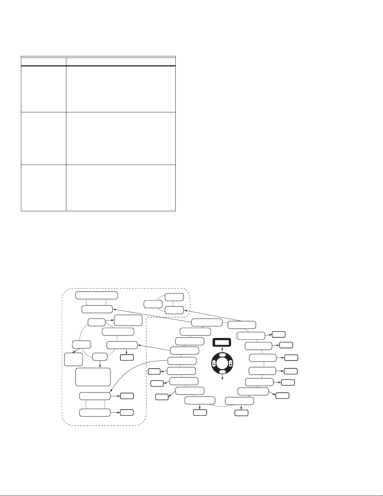
User Interface
Interface Techniques:
TAP: Press a finger on a button and remove.
SCROLL: Press a finger on the glass and move the finger
in circles (twirl).
RAMP: Hold a finger on the + or - button.
Two button interface (BACK and ENTER). Everything else
can be done by scrolling.
Interface Modes:
FLAME DISPLAY: Tap BACK (may require more than on
tap).
HELP: Tap + or - (from display).
LAST MENU: Tap ENTER, move through menu with taps or
scrolls.
ADJUST MODE: Tap ENTER from adjustable menu item,
change value using any technique.
NO YES MODE: Change to YES and tap STORE.
NOTE: If a sensor is not available in your model, then no menu item will exist for sensor setting. See Table 1, “Models
32-00015—04 10
and Associated Features.,” on page 2 to determine which sensors are active in your U2 model.
Fig. 6. User interface menu overview.

U2-S MODEL COMBINATION VIEWING HEAD AND SIGNAL PROCESSOR
WARNING
WARNINGWARNING
WARNING
WARNINGWARNING
U2-S Flame Threshold Setup
Desired target burner flamecount during normal
operation is 1200 to 2000 counts.
Using multiple sensors is useful for monitoring different
fuels, pilot/main flame monitoring, or for a high level of
discrimination. See feature chart on page 2 for application
sensors.
Positioning of flame scanner, along with gain and
filter settings must result in a background
radiation flamecount that is less than the flame off
setpoint! (Example: If target flame is extinguished,
but background flame(s) are still present,
flamecount must fall below flame off setpoint).
Recommended Ideal Flame On and Flame Off threshold
settings:
1. Adjust available sensor filters to 0, and gain of each
sensor so that flamecount under normal operation is
approximately 1500 to 2000 counts total when viewing target flame under normal firing rate.
2. Take a reading of the Flame On and Flame OFF
flamecount values at minimum firing rate and Maximum firing rate:
f. Target burner Flame ON flame count at lowest
firing rate = AL
g. Target burner Flame Off, flame count at lowest
firing rate = BL
h. Target burner Flame ON flame count at highest
firing rate = AH
i. Target burner Flame Off, flame count at highest
firing rate = BH
j. Select AL if AL < AH, otherwise use AH value.
Let us call this value = X
k. Select BH if BH < BL otherwise use BL value.
Let us all call this value =Y
3. Use X, Y, along with formulas below to arrive at new
Flame ON, and Flame OFF thresholds.
Flame ON set point = 0.75X + 0.25Y
Flame OFF set point = 0.25X + 0.75Y
4. Using new values for Flame On and Flame Off
threshold, calculate FLAME ON/Flame OFF ratio.
The ratio of 1.5 or higher is desirable. Adjust flame
ON and flame OFF thresholds to calculated values in
step 3.
5. Extinguish target flame while maximum background
radiation is present. Observe flamecount, and
increase filter setting(s) of sensor(s) to decrease
total flamecount present from background radiation. The resulting background radiation flamecount
should be adjusted to minimum. Verify that resulting
flamecount falls below the flame off setpoint. If not,
continue adjusting gain and filter settings, or adjust
target flame sighting.
After setup is complete, installer must test for
background flame radiation below flame off
setpoint when target flame is extinguished over all
conditions. Failure to verify this may result in
unsafe operation.
6. When filtering settings are complete, operate system
once again with all flames present over minimum
and maximum load, and verify proper flame threshold operation. If no further adjustment is necessary,
threshold setup is complete. If gain or filter adjustments are necessary, repeat step 5 to confirm background radiation below flame OFF setpoint as any
adjustments will affect both the target and background radiations.
11 32-00015—04
32-00015—04 12
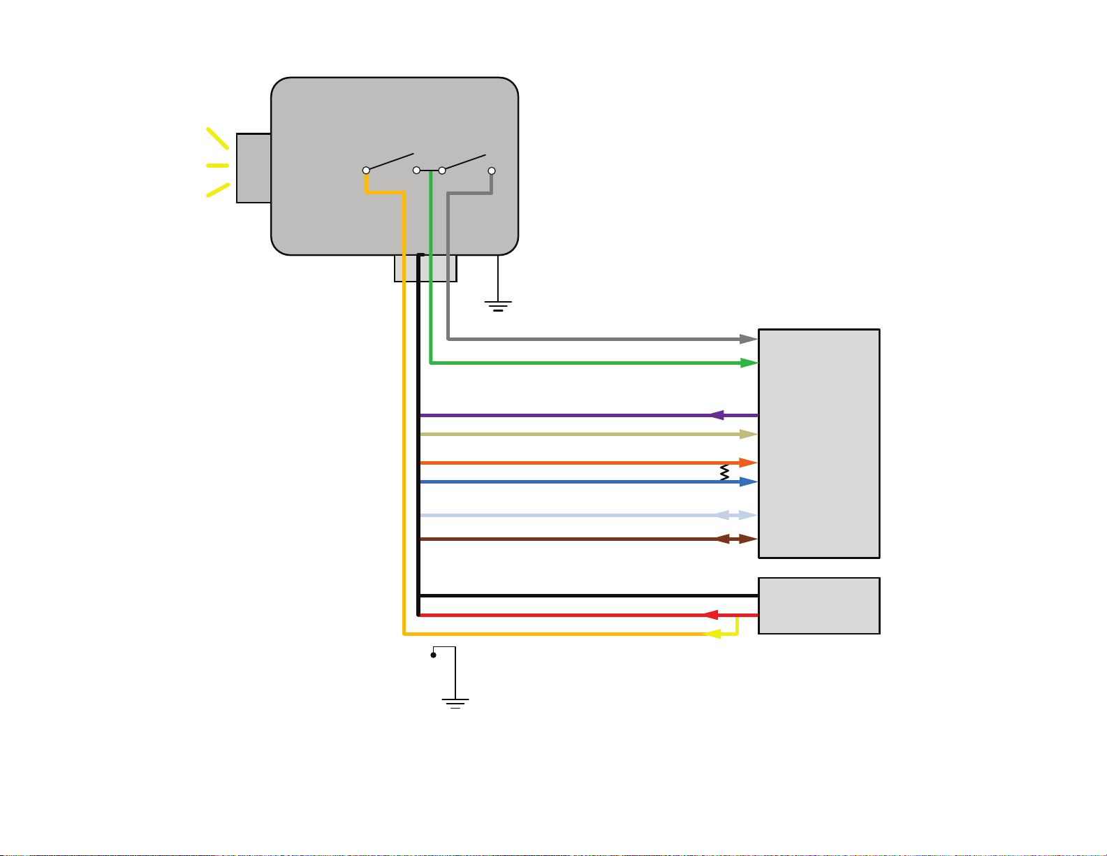
(GREY) FLAME SIGNAL OUTPUT 30VDC 1A MAX
(GREEN) FAULT SIGNAL OUTPUT 30VDC 1A MAX
(YELLOW) FLAME SIGNAL INPUT 30VDC 1A MAX
(PURPLE) FILE SELECT INPUT 30VDC MAX
(TAN) FILE SELECT OUTPUT 24VDC 10ma MAX
(ORANGE) mA OUPUT + 500Ω MAX
(BLUE) mA OUPUT - 500Ω MAX
(WHITE) RS485+
(BROWN) RS485-
(RED) +24V INPUT 120mA MAX
(BLACK) POWER SUPPLY
MCR35492
SCREW
TO EARTH
GROUND
CABLE DRAIN
TO EARTH
GROUND
FLAME
RELAY
SELF
CHECK
RELAY
U2-101xS
FLAMESCANNER
BURNER
CONTROL
SYSTEM
500Ω
MAX
24VDC SELV
POWER SUPPLY
U2-S MODEL COMBINATION VIEWING HEAD AND SIGNAL PROCESSOR
Fig. 7. Typical Installation Diagram.
U2-S MODEL COMBINATION VIEWING HEAD AND SIGNAL PROCESSOR
SAFETY MANUAL
U2-S Model Product Declaration
FIT FOR USE IN A LOW DEMAND SAFETY APPLICATION
Models:U2-1010S, U2-1012S, U2-1016S, U2-1018S, U2-1010S-PF, U2-1012S-PF, U2-1016S-PF, U2-1018S-PF
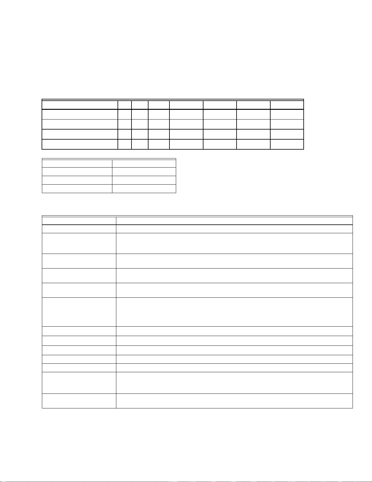
Models SIL HFT SFF PFD
U2-1010S/U2-1010S-PF 3 0 >99%
U2-1012S/U2-1012S-PF 3 0 >99%
U2-1016S/U2-1016S-PF 3 0 >99%
U2-1018S/U2-1018S-PF 3 0 >99%
1.20 x10
1.16x10
1.15x10
1.16x10
-4
-4
-4
-4
λ
S
1.23x10
1.64x10
1.06x10
1.16x10
-5
-6
-5
-5
λ
DD
3.34x10
1.77x10
1.74x10
1.77x10
-7
-9
-9
-9
λ
DU
5.38x10
5.32x10
5.27x10
5.32x10
-9
-9
-9
-9
System Architecture 1oo1
MTTR 8 hours
Proof Test Interval 5 years
Fit for use in SIL 3 environment
Definitions
Term Definition
Dangerous Failure Failure which has the potential to put the safety-related system in a hazardous state
Safety-Related System A system that implements the required safety functions required to achieve or maintain a
Safety Function Defined function, which is performed by a safety-related system with the aim of achieving
Proof Test Periodic test performed to detect failures in a safety-related system so that, if necessary, the
MTTR (Mean Time To
Restoration)
λ
sd
λ
su
λ
dd
λ
du
HFT Hardware Fault Tolerance
System Architecture Specific configuration of hardware and software elements in a system.
PFD
(Average
AVG
Probability of Failure on
Demand)
FIT (Failures in Time) A unit of measurement representing one failure per billion hours. 1,000,000,000 hours is
safe state and is intended to achieve on its own or with other systems the necessary safety
integrity for the required safety functions.
or maintaining a safe state for the plant, in respect of a specified hazardous event.
system can be restored to an “as new” condition or as close as practical to this condition.
The average duration required for restoration of operations after a failure.
Rate of safe detectable failures per one billion hours.
For example, if λ
= 3000, then it is estimated that there will be about 3000 safe detectable
sd
failures during every one billion hours of operation.
For λ
= 3000, this is about one safe detectable failure every 38 years.
sd
Rate of safe undetectable failures per one billion hours.
Rate of dangerous detectable failures per one billion hours.
Rate of dangerous undetectable failures per one billion hours.
Average Probability of Failure on Demand.
approximately 114,155.25 years.
13 32-00015—04
U2-S MODEL COMBINATION VIEWING HEAD AND SIGNAL PROCESSOR
Safety Function of the U2-S Model
The safety function of the U2-S signal processor consists
of a Flame Relay which comprises its safety function and
behaves as follows:
The Flame Relay (Normally Open)
• The Flame Relay will be energized when the product is
powered and a flame on condition is detected for longer
than the time delay value.
• The Flame Relay will be de-energized when the product
is powered, a flame off condition is detected, and the
FFRT (Flame Failure Response Time) has elapsed.
• The Flame Relay will be de-energized when the product
is powered and detects a fault condition.
• The Flame Relay will be de-energized when power to
the product is off.
All U2-S signal processor models contain a Self Check
Relay designed to be energized during normal operation
and de-energized during power off, or detection of a fault.
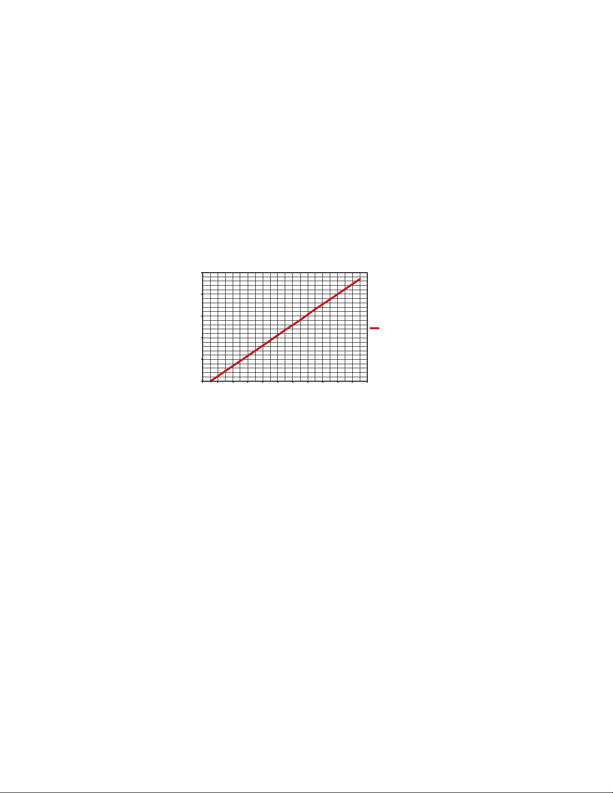
Proof Test Interval
The Proof test must be conducted every 1 to 5 years. This
range is given to allow for the test to be performed during
the normally scheduled burner shutdown period. It is the
responsibility of the user to perform the proof test in the
specified time frame.
The following chart for the U2-1010S shown for example,
presents the dependence of the PFD
interval. The PFD
increases.
on the proof test
increases as the proof test interval
AVG
AVG
2.53E-04
2.03E-04
1.53E-04
1.03E-04
5.27E-05
2.71E-06
U2-1010S TIME IN YEARS VS PFDavg
012345678910
Fig. 8. 1010S PFD
Proof Test Procedure
EQUIPMENT REQUIRED
• Powered Uniscan 2S signal processor
• Multimeter capable of voltage measurements < 50V,
and resistance measurements 1 Ohm to 1MOhm. Fluke
87 or similar.
• 24V DC Power supply < 500mA
• Light source* capable of generating a flame on
condition for all sensors.
* Use an incandescent bulb for IR sensor, deep UV light for
solid state UV and UV tube sensors. If none of these are
available a flame may be used. Note that IR, and SSUV
sensors require flickering light source.
Setup
1. Set power supply to OFF. Connect U2-S model to
power supply as described in manual.
2. While performing the proof test, disconnect or disregard the signal processor so that any outputs due to
testing do not affect the overall safety system and
potentially cause a hazardous situation.
3. Record all previously entered user programmable
settings so that they may be restored after the proof
test.
PFDavg
MCR35675
over time.
AVG
Tests
1. Ensure that power is completely removed form the
U2-S. Measure resistance between yellow and green
wires and verify that self check relay contact is open
circuit ( >1MOhm ). Measure between green and
gray, and verify flame relay contact is open circuit (>
1MOhm).
2. Reapply power to the signal processor and, using a
multimeter, ensure closure of the self check relay by
measuring continuity * between the yellow and
green wires.
* Less than ~5ohm / 50foot cable
3. Use a light source to generate a flame on condition
and, using a multimeter, ensure closure of the flame
relay by measuring continuity between the green
and gray wires.
4. Remove any light source to generate a flame off condition and, using a multimeter measure resistance
between green and gray wires, and verify flame relay
contacts are open ( > 1MOhm), after the FFRT
(Flame Failure Response Time) has elapsed.
5. Measure the current draw of the U2 and ensure it is
less than 120 mA.
6. Change FFRT settings of the signal processor and
store the changed setting. Remove power to the signal processor for 10 seconds. Restore power to the
signal processor and ensure the stored value has
remained unchanged.
32-00015—04 14

U2-S MODEL COMBINATION VIEWING HEAD AND SIGNAL PROCESSOR
7. Use your light source to generate flamecounts of
between 1200 and 2000 in the signal processor.
Note the flamecount.
a. Increase the gain and store the setting. Confirm
the flamecount increased.
b. Decrease the gain and store the setting. Confirm
the flamecount decreased.
8. Restore all original settings as recorded in setup and
reconnect the signal processor to the safety system.
Product Decommissioning
When required, decommissioning of the U2-S
flamescanner should be performed in accordance with
requirements of the overall safety system.
15 32-00015—04

U2-S MODEL COMBINATION VIEWING HEAD AND SIGNAL PROCESSOR
Automation and Control Solutions
Honeywell International Inc.
1985 Douglas Drive North
Golden Valley, MN 55422-3992
www.honeywell.com
United States
Maxon, A Honeywell Company
201 East 18th Street
P.O. Box 2068
Muncie, IN 47307-0068
Tel: 765.284.3304
Fax: 765.286.8394
Europe
Maxon International bvba
Luchthavenlaan 16
1800 Vilvoorde
Belgium
® U.S. Registered Trademark
© 2016 Honeywell International Inc.
32-00015—04 M.S. Rev. 05-16
Printed in United States
 Loading...