

Honeywell TMS 9250 User Manual

TMS 9250 Product User Manual
Rev B
April 2012
© 2012 – Honeywell International Inc. All rights reserved


About This Document
Release Information
Document Name Document
ID
TMS 9250 Product User Manual V 1.1a January
Rev B April 2012
Release
Number
Publication
Date
2012
iii TMS 9250 Product User Manual Rev B
April 2012
© 2012 – Honeywell International Inc. All rights reserved

Indicates a situation which, if not avoided, may result in equipment or work
: Indicates a potentially hazardous situation which, if not avoided,
: Indicates a potentially hazardous situation, which, if not avoided,
L'inobservation de ce symbole risque d'entraîner des blessures graves, voire
additional information. The symbol appears next to required information in the
symbole d'AVERTISSEMENT apparaît sur l’équipement et renvoie
Symbol Definitions
The following table lists those symbols used in this document to denote certain conditions.
Symbol Definition
ATTENTION: Identifies information that requires special consideration.
TIP: Identifies advice or hints for the user, often in terms of performing a task.
REFERENCE - EXTERNAL: Identifies an additional source of information
outside of the booklet.
REFERENCE - INTERNAL: Identifies an additional source of information within
the booklet.
CAUTION
(data) on the system being damaged or lost, or may result in the inability to
properly operate the process.
CAUTION
may result in minor or moderate injury. It may also be used to alert against
unsafe practices.
CAUTION symbol on the equipment refers the user to the product manual for
additional information. The symbol appears next to required information in the
manual.
WARNING
could result in serious injury or death.
AVERTISSEMENT : Indique une situation potentiellement dangereuse.
mortelles."
WARNING symbol on the equipment refers the user to the product manual for
manual.
Ce
l’utilisateur aux informations qui se trouvent dans le manuel du produit. Dans le
manuel, ce symbole apparaît à côté de l’information corr e sp ondan te.
WARNING, Risk of electrical shock: Indicates potential shock hazard where
HAZARDOUS LIVE voltages greater than 30 Vrms, 42.4 Vpeak, or 60 VDC may
be accessible.
AVERTISSEMENT, risque d’électrocution : Indique un risque d'électrocution car
des tensions supérieures à 30 Vrms, 42,4 Vpic ou 60 Vcc, POUVANT ETRE
MORTELLES, sont accessibles.
v TMS 9250 Product User Manual Rev B
April 2012
© 2012 – Honeywell International Inc. All rights reserved

Symbol Definition
ESD HAZARD: Indicates dan ger of an electro-static discharge to which
equipment may be sensitive. Observe precautions for handling electrostatic
sensitive devices.
Protective Earth (PE) terminal: Provided for connection of the protective earth
(green or green/yellow) supply system conductor.
Functional earth terminal: Used for non-safety purposes such as noi se
immunity improvement. NOTE: This connection shall be bonded to Protective
Earth at the source of supply in accordance with national local electrical code
requirements.
Earth Ground: Functional earth connection. NOTE: This connection shall be
bonded to Protective Earth at the source of supply in accordance with national
and local electrical code requirements.
Chassis Ground: Identifies a connection to the chassis or frame of the
equipment shall be bonded to Protective Earth at the source of supply in
accordance with national and local electrical code requirements.
vi TMS 9250 Product User Manual Rev B
April 2012
© 2012 – Honeywell International Inc. All rights reserved

Contents
1. TMS 9250 TORQUE MEASUREMENT SYSTEM ................. 9
1.1 Important General and Safety Warni n g s ............................................... 9
1.2 Certification Information ....................................................................... 11
1.3 In The Box ............................................................................................... 12
1.4 Intended Use .......................................................................................... 14
Torque Sensor ..................................................................................................... 14
Usage Scenario of TMS 9250 .............................................................................. 14
1.5 Installation and Setup ........................................................................... 15
Bolting Information ............................................................................................... 15
Torque Sensor ..................................................................................................... 15
Caliper Coupling Module ..................................................................................... 16
Signal Processing Module ................................................................................... 17
SPM External Connection.................................................................................... 17
SPM Internal Connection ..................................................................................... 18
Powering of Device .............................................................................................. 18
Toolkit Installation ................................................................................................ 18
2. MODES OF OPERATION ................................................... 25
2.1 Normal Mode Operation Detailed Description .................................... 25
Normal Mode Operation ...................................................................................... 25
2.2 Fast Mode Operation Detailed Description ......................................... 26
Fast Mode Operation ........................................................................................... 26
2.3 Analog Output Characteristics ............................................................. 30
3. CALIBRATION ................................................................... 31
3.1 System Calibration Method .................................................................. 31
3.2 Shunt Calibration ................................................................................... 32
3.3 Recalibration .......................................................................................... 32
4. TROUBLESHOOTING ........................................................ 33
4.1 “Power On” Light Not Showing ............................................................ 33
4.2 “Rotor Active” Light Not Showing ....................................................... 33
4.3 SHUNT Calibration Not Operating ........................................................ 34
4.4 No Communication ................................................................................ 34
5. PRODUCT SPECIFICATIONS ........................................... 37
6. APPENDICES ..................................................................... 39
vii TMS 9250 Product User Manual Rev B
April 2012
© 2012 – Honeywell International Inc. All rights reserved

6.1 APPENDIX A ........................................................................................... 39
Principle of Telemetry .......................................................................................... 39
6.2 APPENDIX B ........................................................................................... 39
Manual Supplement for TMS 9250 SPM Remote SHUNT CAL Option ............... 39
Overview .............................................................................................................. 39
Setup ................................................................................................................... 39
6.3 APPENDIX C ........................................................................................... 40
Filter Operation General Description ................................................................... 40
Filter Operation Detailed Description ................................................................... 40
Filter Settling Time ............................................................................................... 41
Example............................................................................................................... 42
Sample Charts ..................................................................................................... 44
6.4 APPENDIX D ........................................................................................... 46
Conversion Table ................................................................................................ 46
6.5 APPENDIX E ........................................................................................... 50
Power Supply Positioning and Cleaning .............................................................. 50
6.6 APPENDIX F ............................................................................................ 51
SPM cable connections ....................................................................................... 51
6.7 APPENDIX G ........................................................................................... 58
Manual Supplement for TMS 9250 SPM SQUAREWAVE output Option ............ 58
Overview.............................................................................................................. 58
Setup ................................................................................................................... 58
viii TMS 9250 Product User Manual Rev B
April 2012
© 2012 – Honeywell International Inc. All rights reserved

1. TMS 9250 Torque Measurement System
Complete installation, operation, and maintenance information is
Failure to comply with these instructions could result in death or
Les informations complètes d'installation, d'utilisation et d'entretien
Failure to comply with these instructions could result in serious
sitifs d’arrêt
d’urgence ou de sécurité, ni dans aucune autre application où la
défaillance du produit pourrait entraîner des personnels blessures
SPM and CCM shall be connected to equipment providing low
voltage (not more than 33Vac rms / 46.7V peak or 70Vdc total)
1. TMS 9250 Torque Measurement System
1.1 Important General and Safety Warnings
Before you work on any electronic equ ipment, review and follow the safety guidelines to hel p
protect the system from potential damage and to ensure personal safety.
WARNING
MISUSE OF DOCUMENTATION
•
provided in the instructions supplied with each product.
•
serious injury.
AVERTISSEMENT
MAUVAIS USAGE DE LA DOCUMENTATION
•
sont fournies avec les instructions ac compagnant chaque produit.
• L'inobservation de ces instructions risque d'entraîner des blessures
graves, voire mortelles.
008-0738-00
WARNING
PERSONAL INJURY
• DO NOT USE these products as safety or emergency stop devices
or in any other application where failure of the product could result
in personal injury.
•
injury or death.
AVERTISSEMENT
PERSONNELS BL E SSU RES CORPORELL E S
• NE PAS UTILISER ces produits en tant que dispo
corporelles.
• L'inobservation de ces instructions risque d'entraîner des blessures
graves, voire mortelles.
CAUTION
• For continued protection from electrical shock, all connectors on the
double insulated (SELV) sources of supply.
• When you are adjusting the CCM to align with the torque sensor,
you must lock out power to the prime mover and ensure that you
are trained prior to accessing these areas of the installation.
Rev B TMS 9250 Product User Manual 9
April 2012
© 2012 – Honeywell International Inc. All rights reserved

1. TMS 9250 Torque Measurement System
The SPM is intended only for connection to the specific power
The system was evaluated for use with a specific SELV power
ther power supply with this system may result in
The CCM is intended only for connection to the SPM with cables
This equipment provides only low voltage double insulated signal
Due to the multitude of variations possible for connection of the
guarding for the end application to meet provisions of the
Directive and RTTE Directives and is not evaluated to the
machinery directive for the reasons stated. Therefore, you must
ensure the compliance of this equipment with the provisions of the
will normally
mandate the need for additional guarding at the mechanical
Place the power supply of the system in a place where you can
008-0738-00
CAUTION
•
supply shipped with the system.
•
supply of limited energy output that affords electrical fire and shock
hazard protection.
• The use of ano
electrical shock or fire hazards or non-compliance of certification
standards.
•
provided by the manufacturer.
• Refer to the APPENDIX F for connecting cables to the SPM.
•
I/O for connection to other equipment.
ATTENTION:
• The product shall be in “POWER ON” condition for minimum period
of 30-45 minutes for meeting the product output specifications and
emission standards.
ATTENTION:
• Ensure that the interface cables are shielded before connecting to
•
• The equipment is evaluated only with respect to the Low Voltage
TIP
•
the product.
torque sensor to the load and prime mover, you must increase the
machinery directive.
machinery directive in the end application. This
coupling points to the torque sensor.
easily unplug the power cords.
10 TMS 9250 Product User Manual Rev B
April 2012
© 2012 – Honeywell International Inc. All rights reserved

1.2 Certification Information
FCC statement: (1) this device may not cause harmful interference,
and (2) this device must accept any interference received, including
exempt RSS standard(s). Operation is subject to the following two
conditions: (1) this device may not cause interference, and (2) this
Canada applicables aux appareils radio exempts de licence.
accepter tout brouillage radioélectrique subi, même si le brouillage est
Certification
FCC ID: XJLTMS9250FCC
IC ID: 9832A-TMS9250IC
interference that may cause undesired operation.
IC statement: This device complies with Industry Canada license-
device must accept any interference, including interference that may
cause undesired operation of the device.
déclaration IC : Le présent appareil est conforme aux CNR d’Industrie
L’exploitation est autorisée aux deux conditions suivantes: (1) l’appareil
ne doit pas produire de brouillage, et (2) l’utilisateur de l’appareil doit
1. TMS 9250 Torque Measurement System
008-0738-00
susceptible d’en compromettre le fonctionnement.
EMC
Safety
Product meets EMC/EMI requirement as per following standards:
• Class B FCC § 15.225(a)
• Class B FCC § 15.225(d)
• Class B FCC § 15.207
• IC RSS-Gen Issue3
• IC RSS-210 Issue 8
• ETSI EN 300 330-1 V1.7.1 and ETSI EN 300 330-2 V1.5.1
• ETSI EN 301 489-1 V1.8.1 and ETSI EN 301 489-3 V1.4.1
Product is meeting safety requirement as per following standard
• EN 60950-1: 2006 + A11:2006 and IEC 60950-1: 2005 (second edition)
• EN 61010-1: 2001 (second edition) and IEC 61010-1: 2001(second edition)
Rev B TMS 9250 Product User Manual 11
April 2012
© 2012 – Honeywell International Inc. All rights reserved
1. TMS 9250 Torque Measurement System
008-0738-00
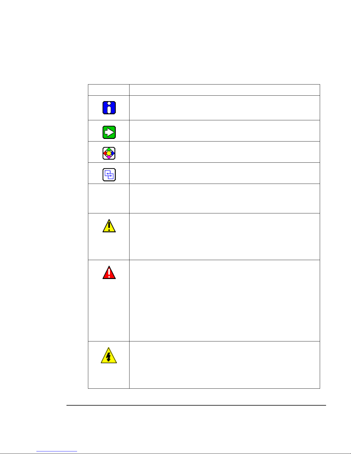
1.3 In The Box
Sl no. Description Part
1 Rotor
2 Caliper Coupling Module (CCM)
3 Alignment Tool / Setting Gauge
4 RF Tri-Axial Cable
5 Signal Processing Module (SPM)
12 TMS 9250 Product User Manual Rev B
April 2012
© 2012 – Honeywell International Inc. All rights reserved
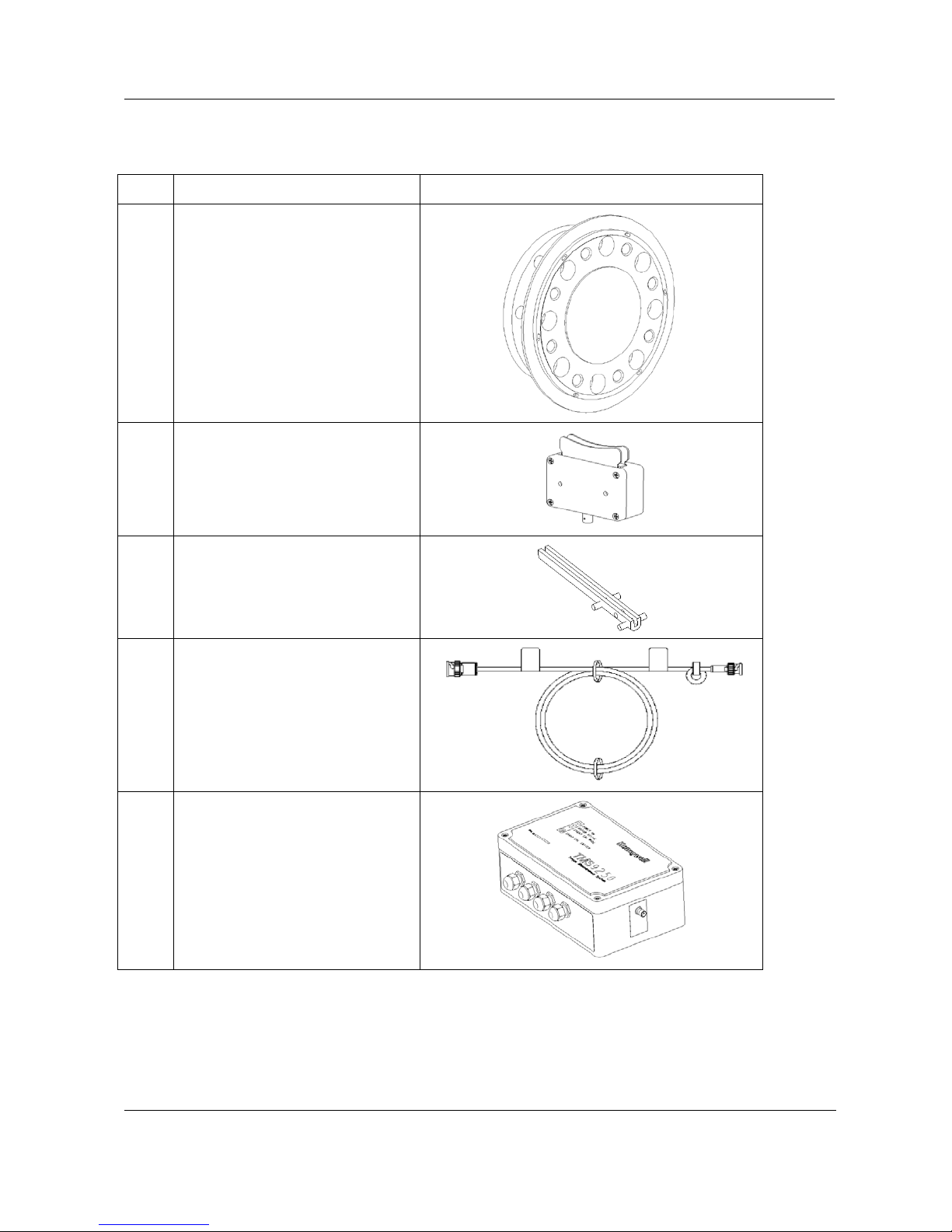
6 RS232 Interface Cable
(Communication cable)
7 Plug Top
8 Power Adapter
9 Software Installation CD
1. TMS 9250 Torque Measurement System
008-0738-00
10 Product User Manual
11 Toolkit Software Manual
Rev B TMS 9250 Product User Manual 13
April 2012
© 2012 – Honeywell International Inc. All rights reserved
1. TMS 9250 Torque Measurement System
008-0738-00
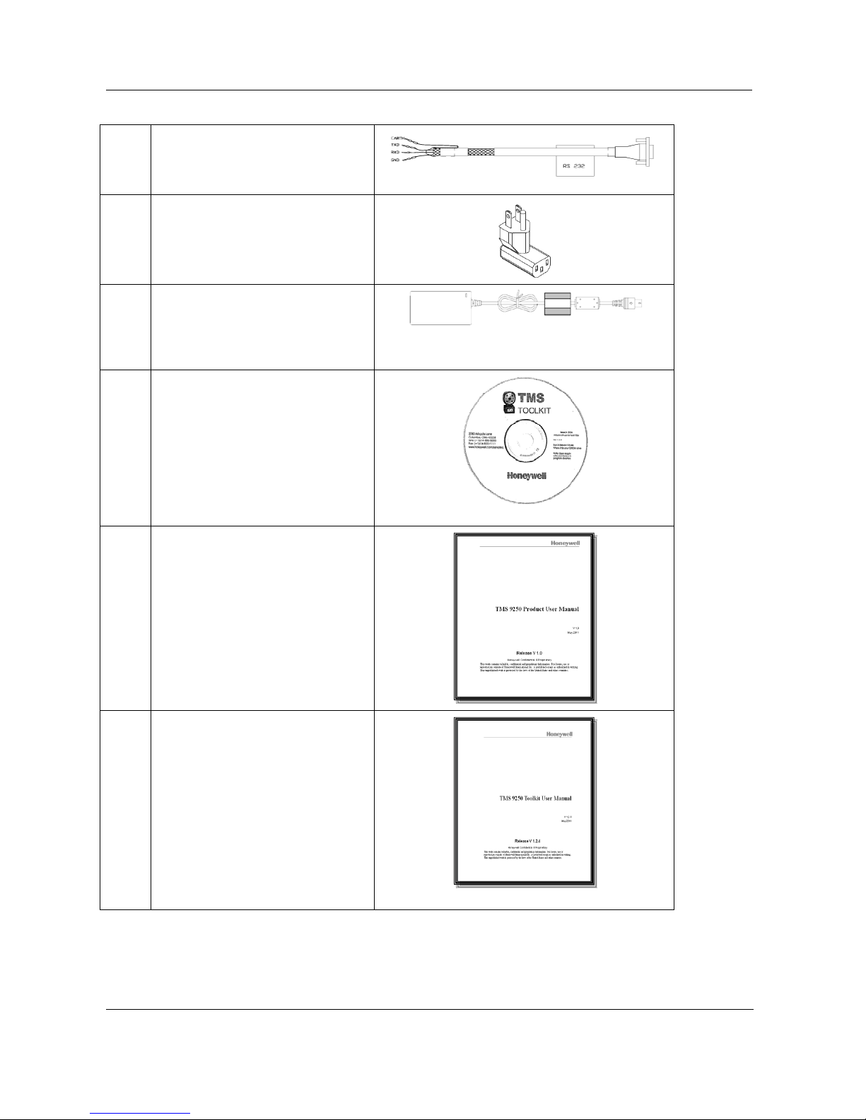
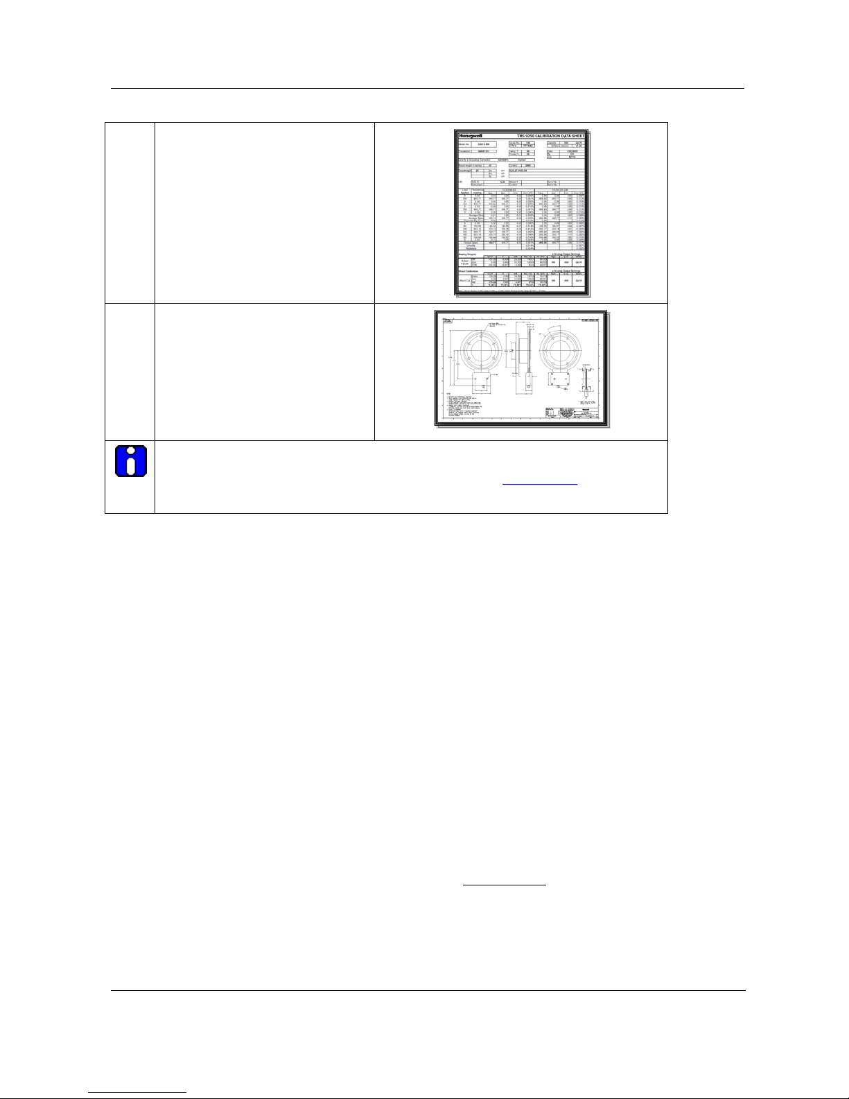
12 Calibration Sheet
13 Outline Dimension Drawings (ODD)
Note:
• RS232 Interface cable connection is mentioned in
• P ictures shown above are for representation only, not to actual scale.
APPENDIX F step 5.
1.4 Intended Use
Torque Sensor
Honeywell Torque Sensors are dedicated structures that perform in a predictable and
repeatable manner wh en torque f orces are a pplied. This torque f orce is tr anslated i nto a sig nal
voltage by the resistance change of strain gages, which are attached to the torque sensor
structure. The change in r esistance indic ates the degr ee of deformat ion, and in t urn, the torque
force on the structure.
The strain gages are connec ted in a four arm Wheats tone bri dge conf igurati on whic h acts as an
adding and subtracting ele ctrical network and allows compensati on for temperature effects as
well as cancellation of signals caused by extraneous loading.
When the torque sens or is rotati ng, a means m ust be prov ided to trans fer an excitat ion voltage
to the rotational el ement from a stationary s urface, and also to transfer the torque signal from
the rotational element bac k to the stationary surface. This is acc omplished through the use of
digital telemetry.
Usage Scenario of TMS 9250
This product is used in controlled environment, not intended for outdoor use and designed
typically for dynamometer test laboratories.
Refer to the cleaning instructions provided in the
APPENDIX E.
14 TMS 9250 Product User Manual Rev B
April 2012
© 2012 – Honeywell International Inc. All rights reserved
1.5 Installation and Setup
sunpower
SPM
CCM
Power
Supply
Belden Tri-axial RF cable
Plug Top
DC Cable
To SPM
RS 232 Cable For
Computer Interface
Analog V/mA
Output
Frequency
Output
Rotor
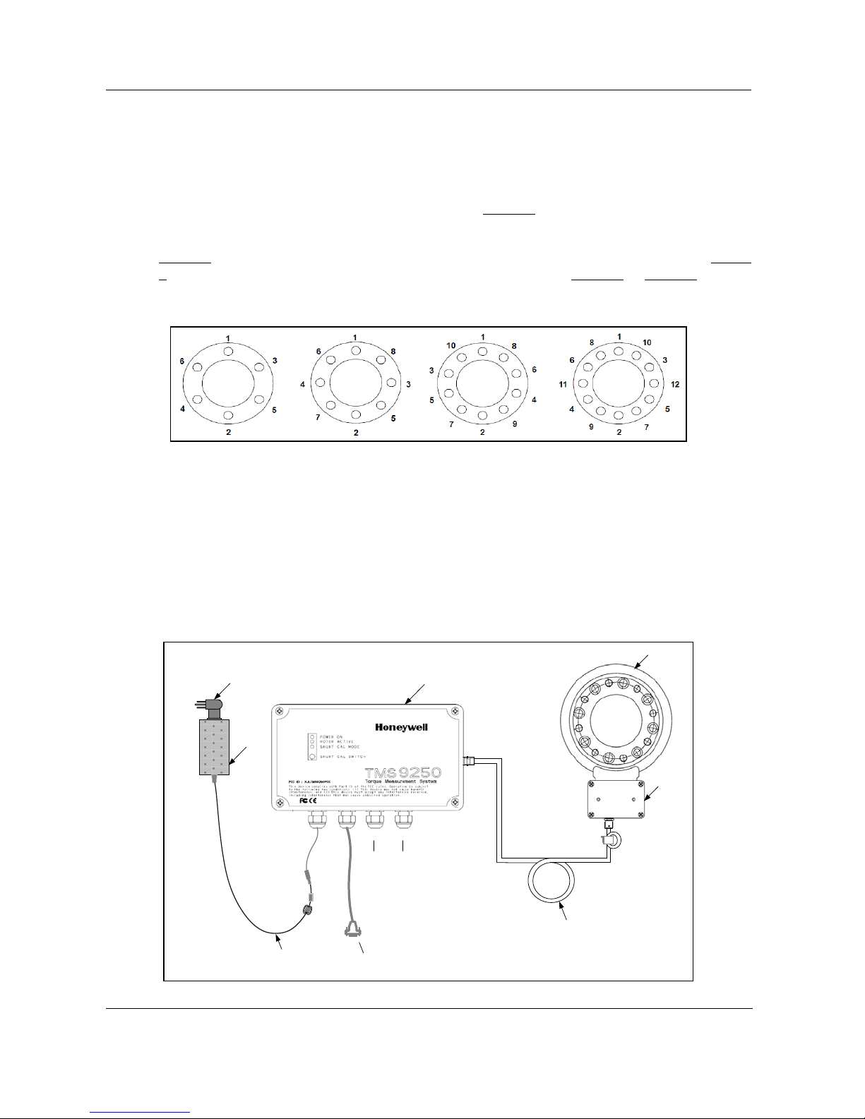
Bolting Information
Tighten all bolts, in incremental steps, to the bolt manufacturer’s rated torque specification.
Use the respective sequence illustration shown in
the sensor requires. This bolting sequence applies to both bolt circles of the to rque sensor.
Typical connection schematic of the product for any torque measurement is as shown in
Figure 2. General gu idelines shall be c onsidered for moun ting the sensor as shown in Figure
3. Outlin e dimension d etails for standar d models ar e indicated in Figure 4 to Figure 9; contact
factory for other configurations.
Figure 1: Bolting Pattern for Flange Model
1. TMS 9250 Torque Measurement System
008-0738-00
Figure 1 depending on the number of bolts
Torque Sensor
Honeywell's TMS 9250 series torque sensors may be operated horizontally, vertically, or at
any angle in between, provi ded the load is ap plied t hrough t he load ing ax is. Al l torque s ensors
in this series have bolt patterns that mate directly to standard DIN compa nion flanges. When
mounted, one of the flanges should be mated to a good quality double flex coupling or a
driveshaft arrangement that incorporates universal joints at each end. This is designed to
compensate for angular and parallel misalignment. Avoid applications that place extraneous
loads on the torque sensor.
Rev B TMS 9250 Product User Manual 15
April 2012
© 2012 – Honeywell International Inc. All rights reserved
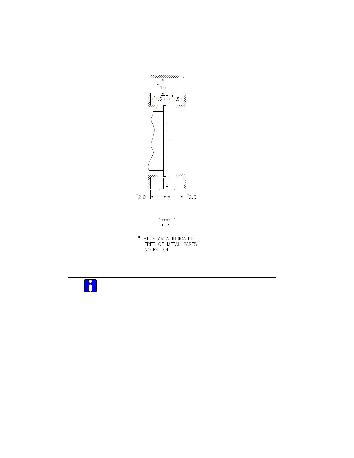
1. TMS 9250 Torque Measurement System
and 2.0 inches
008-0738-00
Figure 2: Complete Setup Connection Representation
Figure 3: General Precautions to be Considered for Rotor and CCM Installation
Note:
1. Pilot diameters in accordance with ANSI B4.1 (ANSI
standards for limits and fits)
2. Mating driveline components shall be more than 1.5
inches around the rotating antenna
around CCM.
3. Minimum s afety shield clearance of 1.5 inches shall be
provided between the rotating antenna and test stand
safety shields.
4. Signal loss will occur if maximum component diameter
or minimum safety shield clearance is not maintained
more than 2.0 inches around CCM.
Caliper Coupling Module
The caliper coupling module must be firmly mounted to a non-rotating support structure. It
must be aligned with the annular printed circuit board antenna so that the air ga p between the
16 TMS 9250 Product User Manual Rev B
April 2012
© 2012 – Honeywell International Inc. All rights reserved

caliper and the antenna is approximately equa l on both sides. Care should be taken to avoid
any items touching one another, and consideration should be given to the effects of
vibration as well as the free play in any driveshaft sliding joints.
To assist in the process of aligning the caliper and the antenna, a simp le plastic alignment tool
is provided with each system. The tool is used to hold the required clearance between the
caliper and the antenna while the ca liper fixing b olts are bein g tightened, and then is removed
before the sensor is rotated.
The tolerances for end-float (axial) are i.e. +/- 3/16 in. (+/- 3.5 mm) and for run out (radial) are
+/- 1/16 in. (+/- 1.0 mm). For installations where run-out cannot be controlled within the
specified tolerance, the secondary coupling position can be used. This is achieved by
placing the edge of the caliper in close proximity to the edge of the antenna. In this position,
the run-out tolerance can b e at least doubled, at the expense of a reduced signa l t o noise r a ti o
caused by the higher incidence of data drop outs. The axial tolerance is limited by the
distance between the caliper sections.
The caliper can also be mounted such that only one side is in prox imity to the antenna, if
the mounting arrangement does not allow for placing of the antenna between the two sides of
the caliper.
Successful positioning of the caliper can be confirmed by the quality test of the TMS Toolkit
returning >97% result. Th e pr ocedure t o run t he qual ity is explain ed in Toolkit manual su pplie d
with product.
The length of the RF cable connection between the caliper coupling module and the signal
processing module is critical to sy stem performance (due to ref lections and standing waves).
You must use tri-axial cable only of length 14.6 meters (47 ft. 11 in.) supplied with the
product.
Signal Processing Module
The receiver is mounted remote ly with the tri-axial ca ble being the only connection between it
and the caliper coupling module. The receiver has holes provided for permanent mounting.
Customer shall request appropriate certified drawings from Ho neywell before making fixtures
for mounting in racks.
When deciding where to locate the signal processing module, consideration should be given to
the type of output that will be used. If t he analog voltage or current out put is to be used,
then the signal process ing module should be mounted in an area of low electrical noise,
and the connection between the module and the dat a acquisition equipment should be as
short as possible made up of double sc r eened twisted pair cable. If the frequency output or th e
digital output is to be used, then the signal processing module can be mounted in the
electrically noisy area prov i ded that good quality dual screened twisted pair cables are used.
SPM External Connection
Refer to
APPENDIX F for SPM IO box connections.
1. TMS 9250 Torque Measurement System
008-0738-00
Rev B TMS 9250 Product User Manual 17
April 2012
© 2012 – Honeywell International Inc. All rights reserved
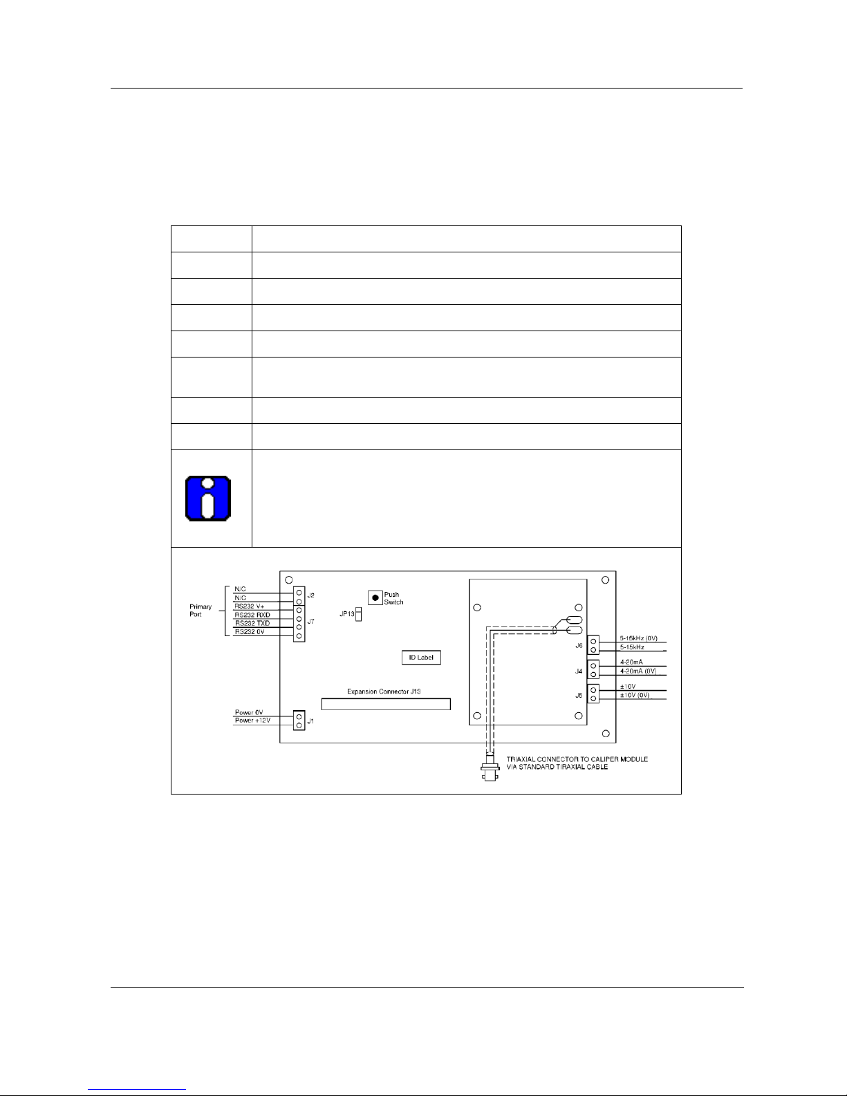
1. TMS 9250 Torque Measurement System
J5 are interchangeable but
connector J6 is neither interchangeable with J4 nor J5. Do not
008-0738-00
SPM Internal Connection
The following table provides detail of internal connection for the SPM. Honeywe ll does not
recommend that the user change these settings/ connections until/unless assisted by the
factory. Table and pin connection details are listed as follows:
Connector Function
J1 DC Power 12 V
J4 Current loop output
J5 Voltage output
J6 Frequency output
J7
J13 Expansion port
JP1 Primary RS232 default select
Primary RS232 port
NOTE: THIS IS THE DEFAULT COMMUNICATIONS PORT
ATTENTION:
SPM shall be configured for either voltage or current output from
factory hence connectors J4 and
attempt to interchange frequency output to any other output.
Powering of Device
After all the connections are completed, the system s hould be powered and al lowed to warmup for 30-45 minutes, in order to get stable outputs from the SPM.
Toolkit Installation
After all the mechanic al and electrical se tup is completed, s oftware should b e installed on the
computer as detailed in the Toolkit Software Manual supplied with the product.
18 TMS 9250 Product User Manual Rev B
April 2012
© 2012 – Honeywell International Inc. All rights reserved
 Loading...