

Page 1
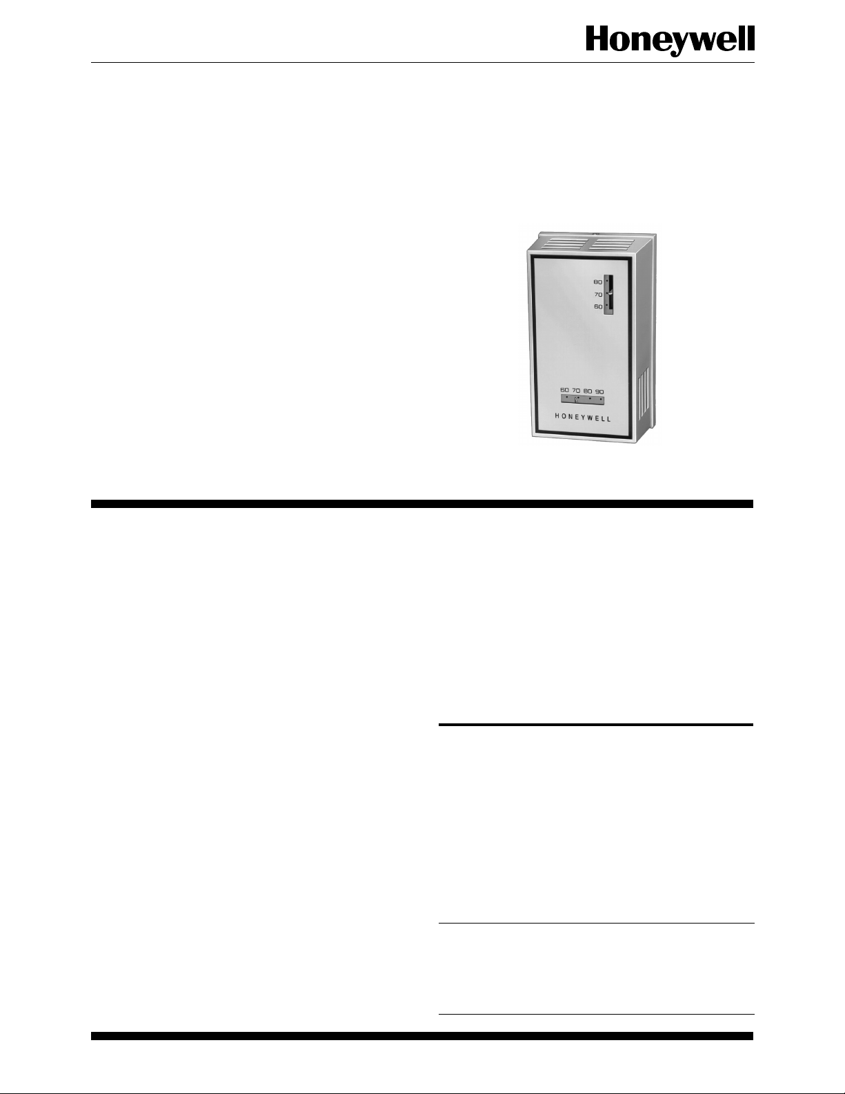
T921A,B,E-G Proportional
Control Thermostats
T921 Thermostats provide 3-wire, low voltage
proportional control for Series 90 (135 ohm) valve
motors, damper motors, and balancing relays in
heating or cooling system applications.
■■ T921A ■■ T921B ■■ T921E ■■ T921F ■■ T921G
■ Accessory faceplates available for horizontal mount-
ing of T921A,B,E models.
■ COOL-HEAT changeover switch in the T921B.
■ Night setback mechanism and switch in the T921E.
■ A spdt (single pole double throw) Class 2 auxiliary
switch in the T921F,G, which operates at the low
(T921F) and high (T921G) end of the throttling
range.
■ A bellows element adjusts the potentiometer slider
to regulate motor operation.
■ Various temperature ranges are available.
■ All models are available with a thermometer and a
locking cover.
CONTENTS
Specifications .................................................2
Ordering Information..................................... 2
Installation .....................................................4
Setting and Adjusting .....................................7
Operation .......................................................7
J. D. • Rev. 1-94 • ©Honeywell Inc. 1994 • Form Number 60-2242—2
1 60-2242—2
Page 2

T921A,B,E-G
SPECIFICATIONS • ORDERING INFORMATION
Specifications
TRADELINE® MODELS
TRADELINE® models are selected and packaged to
provide ease of stocking, ease of handling and maximum
replacement value. TRADELINE® model specifications
are the same as those of the standard models except as noted
below.
TRADELINE® MODEL AVAILABLE:
T921A Thermostat for vertical or horizontal mounting.
TEMPERATURE RANGE AND SCALE:
56° to 84° F [13° to 29°].
ADDITIONAL FEATURES:
• TRADELINE® packed with cross-reference label
and special TRADELINE® instructions.
• T6051A may be used in electric heat systems.
• They all include slotted sides and an add-on faceplate
to allow the thermostat to be mounted horizontally.
They also include the 127246A Adapter Plate Assembly for vertical mounting on a horizontal conduit
box or for horizontal mounting on a vertical conduit
box.
STANDARD MODEL
MODELS:
T921A: Heating or cooling applications.
T921B: Is the same as the T921A but includes a cool-
heat changeover switch.
T921E: Includes a switch and heater that provide a night
setback of approximately 10° F [5.5° C].
T921F: Includes an spdt low voltage Class 2 auxiliary
switch that operates at the low end of the throttling
range.
T921G: Includes an spdt low voltage Class 2 auxiliary
switch that operates at the high end of the throttling
range.
SETTING ADJUSTMENT RANGE:
T921A,B,E-G: 56° to 84° F [13° to 29° C].
T921A,B,E-G: 13° to 29° C [56° to 84° F].
T921A: 42° to 75° F [ 5° to 24° C].
T921A,B: 66° to 95° F [19° to 35° C].
THERMOMETER: Bimetal. Scale ranges T921A only:
45° to 75° F [7° to 24° C]. All other models: 60° to 90° F
[16° to 32° C], 15° to 35° C [59° to 95° F]. T921A is also
available with a blank cover and no thermometer.
AUXILIARY SWITCH DIFFERENTIAL:
T921F: 2° F [1° C].
T921G: 1° F [0.5° C].
THROTTLING RANGE:
Fixed.
T921A: 2.5° F [1° C] midscale.
T921B,E: 4° F [2° C].
T921F: 6° F [3° C].
T921G: 5° F [2.5° C].
Variable.
T921A model available with potentiometer for 5° to
6° F [2.5 to 3° C] throttling range.
ELECTRICAL RATINGS:
Voltage: 24 to 30 Vac.
Auxiliary Switch Contact Rating (When Used For Pilot
Duty): 100 VA at 30 Vac.
DIMENSIONS:
Refer to Fig. 1.
ACCESSORIES (ORDER SEPARATELY):
127246A Adapter Plate Assembly for mounting all mod-
els vertically on a horizontal conduit box. (T921
models are shipped with a faceplate for vertical mounting.)
When mounting the T921A,B,E horizontally, see
Table 1 to order the faceplate with the appropriate
scale. NOTE: Do not mount the T921F,G horizontally.
34297B Thermostat Guard Assembly and 138541A
Mounting Plate.
133722A Thermostat Guard (clear plastic cover).
133723A Thermostat Guard (beige plastic cover).
Ordering Information
When purchasing replacement and modernization products from your TRADELINE® wholesaler or your distributor, refer to the
TRADELINE
1. Model number.
2. Scale range.
3. Accessories, if desired.
If you have additional questions, need further information, or want to comment on our products or services, please write or phone:
1. You local Honeywell Home and Building Control Sales Office (check the white pages of the phone directory).
2. Home And Building Control Customer Satisfaction
60-2242—2 2
®
Catalog or price sheets for complete ordering number or specify—
Honeywell Inc., 1885 Douglas Drive North
Minneapolis, Minnesota 55422 1-800-468-1502
(In Canada—Honeywell Limited/Honeywell Limitee, 740 Ellesmere Road, Scarborough, Ontario M1P 2V9) International Sales
and Service Offices in all Principal Cities of the world. Manufacturing in Australia, Canada, Finland, France, Germany, Japan,
Mexico, Netherlands, Spain, Taiwan, United Kingdom, U.S.A.
Page 3
T921A,B,E-G
SPECIFICATIONS
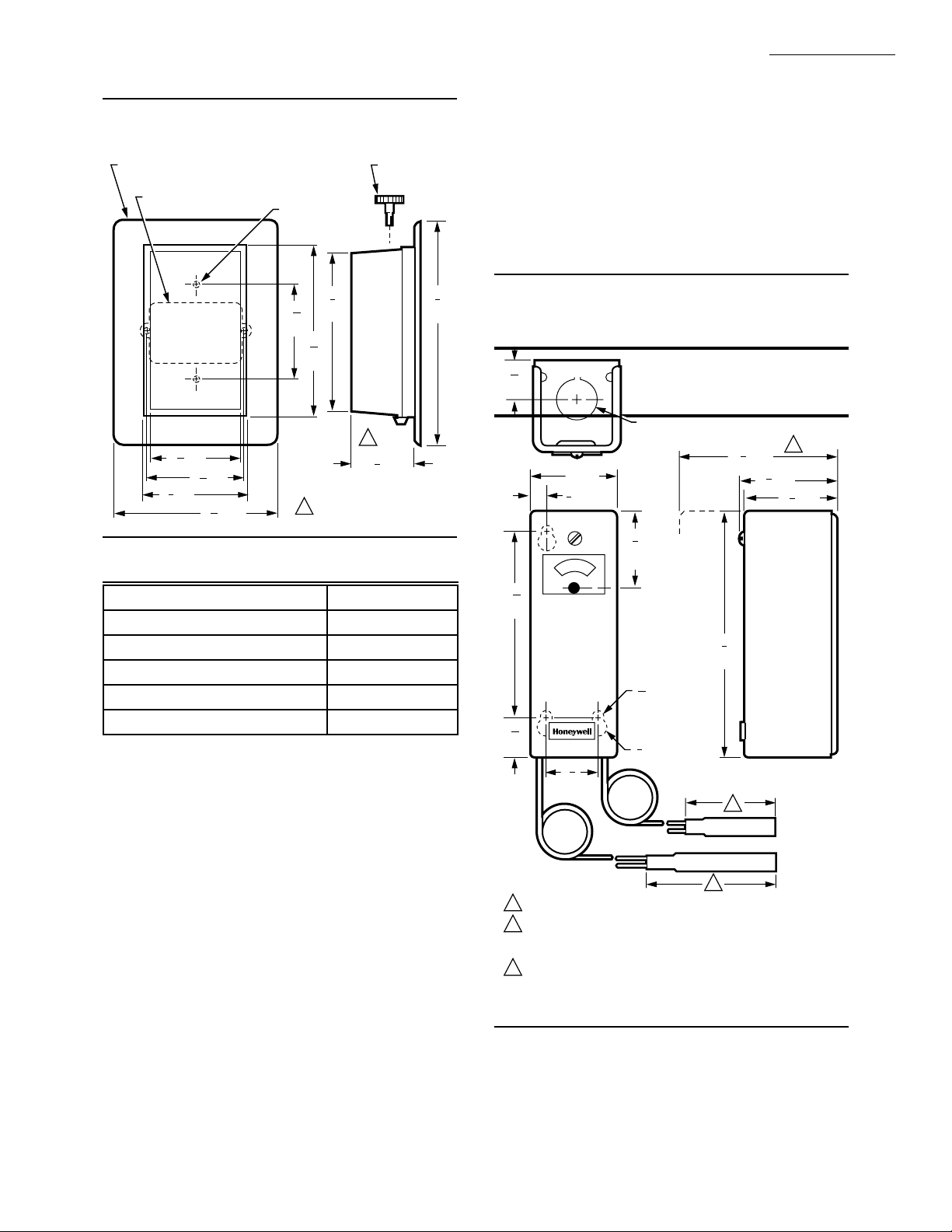
Fig. 1—T921 approximate installation dimensions in in. [mm].
ACCESSORY ADAPTER PLATE (127246A) FOR
MOUNTING ON HORIZONTAL CONDUIT BOX
HORIZONTAL CONDUIT BOX
1
3 [78]
16
5
3 [84]
16
3
3 [86]
8
5
5 [135]
16
FOR VERTICAL
CONDUIT BOX (2)
5
3
16
[84]
11
5
16
[145]
2-11/16 [69] INCHES FOR
1
T921F, G MODELS.
5
[137]
3
8
SETTING
ADJUSTMENT
KNOB
1
1
2 [57]
4
7
[194]
M9107
TABLE 1—ACCESSORY FACEPLATE.
Scale Part No.
56° to 84° F [13° to 29° C] 135135A
13° to 29° C [56° to 84° F] 135135B
42° to 75° F [5° to 24° C] 135135C
66° to 95° F [19° to 35° C] 135135D
56° to 84° F [13° to 29° C] 135135C
a
Blank faceplate.
a
REPLACEMENT PART:
130224 Locking Cover Knob.
OPTIONAL SPECIFICATION (USING THE T991B):
Alternate proportional control similar to the T921A, but
uses an outdoor temperature, automatic control point
reset.
T991B with 3-1/2: 1 reset and 50° to 120° F [10° to
49° C] temperature setting scale (when the outdoor
bulb is at 60° F [16° C]).
DIMENSIONS:
Refer to Fig. 2.
ACCESSORIES:
Compression fittings, immersion wells: Refer to the
appropriate specification or the TRADELINE® Catalog.
314439 Mounting Clips: For mounting a capillary tub-
ing (averaging element) in a duct.
7640HX Averaging Element Mounting Kit: For mount-
ing in existing installations where access to the duct
is impractical.
Q615A Enclosure: To protect the device when mounted
outside; splash proof.
801534 Calibration Wrench.
107324A Bulb Holder: For mounting the bulb in a duct.
34886A Outdoor Bulb Shield: To protect the outdoor
bulb mounting.
5
8
Fig. 2—T991B approximate installation
dimensions in in. [mm].
15
16
[24]
KNOCKOUT FOR 1/2 INCH
CONDUIT (BOTH ENDS)
1
4 [108]
4
2 [51]
3
[10]
8
3
1
4
[45]
3
4
16
[106]
5
[143]
7
[6]
32
DIAMETER (3)
15
16
[24]
1
1
4
[32]
1
OUTDOOR BULB SIZE VARIES INVERSELY WITH THE RESET RATIO.
2
INDOOR BULB LENGTH AND DIAMETER IS 4-1/2 [114] INCH BY
1/2 [13] INCH EXCEPT FOR THE AVERAGING ELEMENT WHICH IS
1/8 [3] INCH DIAMETER BY 12 FT. [3 M] LONG.
3
CLEARANCE NECESSARY TO REMOVE COVER.
3
[10]
8
DIAMETER
2
1
2 [57]
4
5
8
1
3
1
2 [57]
8
M9108
3 60-2242—2
Page 4

T921A,B,E-G
INSTALLATION
!
WHEN INSTALLING THIS PRODUCT…
1. Installer must be a trained, experienced service tech-
nician.
2. All wiring must comply with applicable electrical
codes, ordinances and regulations.
3. Do not exceed the ratings listed on the device name-
plate.
4. After the installation is complete, conduct a thorough
checkout of the product operation.
LOCATION
Locate the thermostat about 5 feet [1.5m] above the
floor in an area with good air circulation at average room
temperature.
Do not mount the thermostat where it can be affected by:
— drafts, or dead spots behind doors and in corners.
— hot or cold air from ducts.
— radiant heat from the sun or appliances.
— concealed pipes and chimneys.
— unheated (uncooled) areas such as an outside wall
behind the thermostat.
CAUTION
Disconnect power supply before installation to
prevent electrical shock and equipment damage.
Installation
ADD FACEPLATES FOR HORIZONTAL
MOUNTING (T921A,B,E ONLY)
T921 models are shipped with a faceplate for vertical
mounting. When mounting the T921A,B,E horizontally,
see Table 2 to order the faceplate with the appropriate scale.
NOTE: Do not mount the T921F,G horizontally.
TABLE 2—ACCESSORY FACEPLATE
Scale Part No.
56° to 84° F [13° to 29° C] 135135A
13° to 29° C [56° to 84° F] 135135B
42° to 75° F [5° to 24° C] 135135C
66° to 95° F [19° to 35° C] 135135D
56° to 84° F [13° to 29° C] 135135C
a
Blank faceplate.
Affix the accessory faceplate when mounting the
T921A,B,E models horizontally with contemporary covers. Peel the backing strip from the faceplate and place it
lightly over the vertical faceplate. Align the edges and
corners and make sure the scales align with the markings.
Press firmly over the entire surface. Do not attempt to
reapply once the faceplate has been mounted.
a
MOUNTING
1. Disconnect power supply before installation to pre-
vent electrical shock and equipment damage.
2. Loosen the locking screw at the bottom of the case
with an Allen wrench.
3. Lift off the thermostat cover.
4. Remove the mounting screws that secure the thermo-
stat to the backplate and remove the backplate.
5. Fasten the backplate to the conduit box (see Fig. 3).
Use the 127246A Adapter Plate Assembly (ordered separately) to mount the thermostat vertically on the horizontal
conduit box; or to mount the thermostat horizontally on the
vertical conduit box (see Fig. 4).
NOTE: When an accessory adapter plate is used, fasten the
adapter plate to the conduit box with the two screws
provided. Then fasten the backplate to the adapter plate.
6. Make all electrical connections to the terminals on
the back of the thermostat before mounting the instrument
on the backplate. Refer to the Wiring section.
7. Mount the thermostat on the backplate with the mounting screws.
8. After performing the checkout tests, replace the thermostat cover and tighten the locking screw.
Fig. 3—Vertical mounting of T921A,B,E-G
Thermostats on vertical conduit box.
T921A,B,E Thermostats can also be mounted
horizontally on horizontal conduit box using
add-on faceplate. (Do not mount T921F,G
horizontally.)
NOTE: ACCESSORY FACEPLATE FOR USE WHEN
THE THERMOSTAT IS MOUNTED HORIZONTALLY.
PEEL OFF BACKING AND APPLY OVER VERTICAL
FACEPLATE AFTER MOUNTING IS COMPLETE.
CONDUIT
BACKPLATE
LOCKING
SCREW
BOX
80
70
60
60 70 80 90
HONEYWELL
MOUNTING
SCREWS
COVER
M9037
60-2242—2 4
Page 5

T921A,B,E-G
INSTALLATION
Fig. 4—Vertical mounting of T921A,B,E-G
Thermostats on horizontal conduit box.
T921A,B,E Thermostats can also be mounted
horizontally on vertical conduit box using
add-on faceplate. (Do not mount T921F,G
horizontally.)
NOTE: ACCESSORY FACEPLATE FOR USE WHEN THE THERMOSTAT
IS MOUNTED HORIZONTALLY. PEEL OFF BACKING AND APPLY
OVER VERTICAL FACEPLATE AFTER MOUNTING IS COMPLETE.
CONDUIT
BOX
127246A
ACCESSORY
ADAPTER
PLATE
M9036
60 70 80 90
HONEYWELL
BACKPLATE
MOUNTING
SCREWS
80
70
60
LOCKING
COVER
SCREW
WIRING
Be sure all wiring must complies with applicable electri-
cal codes, ordinances and regulations.
Do not exceed the following electrical ratings:
Voltage: 24 to 30 Vac.
Auxiliary Switch Contact Ratings: 100 VA at 30
Vac.
Make all electrical connections to the terminals on the
back of the thermostat before mounting the instrument onto
the conduit box. Terminal locations for all models are
shown in Fig. 5. Note the difference in terminal designations for the auxiliary switch on the T921F and G. The H
(Heater) terminal on the T921E is a black leadwire.
Typical wiring diagrams are shown in Figs. 6 through
10. Wire the T921 color-to-color when the modulating
motor must drive the valve or damper open on temperature
fall (heating application). When opposite motor action is
required, reverse the B and W connections. Refer to the
appropriate instructions when wiring the 2-position actuator (Figs. 9 and 10).
Fig. 5—Terminals on back of thermostats.
TOPTOP
B
W
R
(BLACK)
T921A, B
TOP
RBW
B
W
R
H (HEATER)
AUXILIARY
SWITCH
TERMINALS
T921E
TOP
T921GT921F
Fig. 6—Typical wiring diagram for T921A.
SERIES 90
1
L1
(HOT)
L2
TRANSFORMER
MODULATING
MOTOR
B
T
W
T
R
2
T921A
B
W
R
B
W
R
B
W
R
RBW
M9038
B
W
1
POWER SUPPLY. PROVIDE DISCONNECT MEANS AND
OVERLOAD PROTECTION AS REQUIRED.
2
INTERCHANGE B AND W CONNECTIONS TO REVERSE
DIRECTION OF MOTOR TRAVEL.
M5989
5 60-2242—2
Page 6

T921A,B,E-G
INSTALLATION • SETTING AND ADJUSTING
Fig. 7—Typical wiring diagram for T921B.
SERIES 90
MODULATING
1
L1
(HOT)
L2
TRANSFORMER
1
2
MOTOR
T
T
POWER SUPPLY. PROVIDE DISCONNECT MEANS AND
OVERLOAD PROTECTION AS REQUIRED.
INTERCHANGE B AND W CONNECTIONS TO REVERSE
DIRECTION OF MOTOR TRAVEL.
2
B
W
R
T921B
B
SUMMER-
COOL
W
R
Fig. 8—Typical wiring diagram for T921E.
1
L1
(HOT)
L2
TRANSFORMER
1
2
TIMER SWITCH
(OPTIONAL)
H
R
T
W
T
B
SERIES 90
MODULATING
MOTOR
POWER SUPPLY. PROVIDE DISCONNECT MEANS AND
OVERLOAD PROTECTION AS REQUIRED.
H TERMINAL IS A BLACK LEADWIRE.
R
W
B
HEATER
T921E
2
WINTER-HEAT
M5992
NIGHT
SETBACK
SWITCH
B
W
M5988A
Fig. 9—Typical wiring diagram for T921F.
SERIES 90
1
L1
(HOT)
L2
TRANSFORMER
2-POSITION
ACTUATOR
1
2
3
MODULATING
MOTOR
B
T
T
CLASS 2 POWER SUPPLY.
INTERCHANGE B AND W CONNECTIONS TO REVERSE
DIRECTION OF MOTOR TRAVEL.
USE FOR CLASS 2 CIRCUITS. MAKES R TO B ON
TEMPERATURE FALL BELOW THROTTLING RANGE:
2˚ F [1˚ C] DIFFERENTIAL. SEE FIG. 10.
2
W
R
T921F
B
W
R
R
B
W
AUXILIARY
SWITCH
Fig. 10—Typical wiring diagram for T921G.
SERIES 90
1
L1
(HOT)
L2
TRANSFORMER
2-POSITION
ACTUATOR
1
2
3
MODULATING
MOTOR
B
T
T
CLASS 2 POWER SUPPLY.
INTERCHANGE B AND W CONNECTIONS TO REVERSE
DIRECTION OF MOTOR TRAVEL.
USE FOR CLASS 2 CIRCUITS. MAKES R TO B ON
TEMPERATURE RISE ABOVE THROTTLING RANGE:
1˚ F [0.5˚ C] DIFFERENTIAL. SEE FIG. 11.
2
W
R
T921G
B
W
R
W
B
R
3
AUXILIARY
SWITCH
B
W
3
M5993
B
W
M5996
TEMPERATURE SETTING
Adjust all T921 models at the top of the thermostat for
vertically mounted models and on the left side for horizontally mounted models using the setting adjustment knob or
an Allen wrench (see Fig. 11). The device is shipped with
the temperature setting indicator at the center of the temperature range. Without removing the cover, turn the setting adjustment knob or use an Allen wrench so the indicator is at the desired average room temperature.
60-2242—2 6
Setting and Adjusting
ADDITIONAL FEATURES:
T921B SUMMER-WINTER CHANGEOVER
The T921B includes a summer-winter changeover switch.
It is labeled COOL-HEAT. For horizontally mounted
models, this switch is located on the left side of the
thermostat. For vertically mounted models, it is located on the top of the thermostat (see Fig. 11).
T921E NIGHT SETBACK
The T921E includes a manual night setback switch
located on the top of the thermostat (see Fig. 11).
Page 7

T921A,B,E-G
SETTING AND ADJUSTING • OPERATION
This switch energizes a heater that offsets the thermostat approximately 10° F [6° C], lowering the
temperature for night operation. Leave this switch in
the OFF position for normal operation; turn it to the
ON position for lower night time temperature.
CALIBRATION
IMPORTANT: Do not recalibrate unless the thermostat
continues to be out-of-adjustment after several hours
of operation.
T921 Thermostats are calibrated at the factory so when
the room temperature matches the setpoint temperature, the
wiper is at the center of the active potentiometer winding.
If the thermostat is out of calibration, proceed as follows
(see Fig. 11):
1. Remove the thermostat cover.
2. Turn the thermostat setting adjustment knob or an
Allen wrench until the valve or damper motor is at midpoint.
3. Loosen the indicator lock screw and move the indicator to room temperature. Tighten the lock screw.
4. Replace the thermostat cover. Recheck the calibration and repeat the procedure if necessary.
Fig. 11—Internal view of vertically mounted
T921 (horizontally mounted model is similar).
POTENTIOMETER
WIPER
1
80
70
60
SUMMER-WINTER (COOL-HEAT) CHANGEOVER SWITCH ON
1
T921B ONLY; NIGHT SETBACK SWITCH ON T921E ONLY.
SETTING
ADJUSTMENT KNOB
TEMPERATURE
SETTING
INDICATOR
INDICATOR
LOCK SCREW
BELLOWS
M9039
In the T921, a vapor-filled bellows moves the potentiometer wiper by expanding or contracting in proportion to
temperature changes. As the wiper moves, the appropriate
motor winding is energized, opening or closing the valve or
damper to compensate for the temperature change in the
controlled area.
Operation of the auxiliary switch in the T921F,G is
shown in Figs. 12 and 13.
See Table 3 for the throttling range of each thermostat.
The T921F Auxiliary Switch makes R-W at the low end of
the throttling range on temperature rise and makes R-B at
2° F [1° C] below the low end of the throttling range on
temperature fall.
The T921G Auxiliary Switch makes R-W at the high
end of the throttling range on temperature fall and R-B at
1° F [0.5° C] above the high end of the throttling range on
temperature rise.
TABLE 3—THERMOSTAT THROTTLING RANGES
Model Throttling Range
T921A 2.5° F [1.5° C] midscale
T921B 2.5° F [1.5° C] midscale
T921E 4° F [2° C]
T921F 6° F [4° C]
T921G 5° F [3° C]
Operation
Fig. 12—T921F auxiliary switch operation.
TEMPERATURE
+3˚ F
[+1.5˚ C]
SETPOINT
TEMPERATURE
-3˚ F
[-1.5˚ C]
R-W MAKES
TEMPERATURE
RISE
2˚ F [1˚ C]
DIFFERENTIAL
THROTTING
RANGE (6˚ F [4˚ C])
TEMPERATURE
FALL
R-B MAKES
M5990
7 60-2242—2
Page 8

T921A,B,E-G
OPERATION␣
Fig. 13—T921G auxiliary switch operation.
TEMPERATURE
TEMPERATURE
+2.5˚ F
[+1.5˚ C]
SETPOINT
TEMPERATURE
-2.5˚ F
[-1.5˚ C]
FALL
R-W MAKES
1˚ F [0.5˚ C]
DIFFERENTIAL
THROTTING
RANGE (5˚ F [3˚ C])
R-B MAKES
TEMPERATURE
RISE
M5991
CHECKOUT
After the thermostat is wired and mounted, check to be
sure the thermostat and controlled equipment are functioning properly. Before proceeding, allow from one to three
hours for the system to stabilize.
T921A
1. Set the temperature setting indicator to room temperature by using the setting adjustment knob, or an Allen
wrench (see Fig. 11). The valve or damper motor should be
at midpoint.
2. Move the setpoint 5° F [3° C] below room temperature. In a heating application, the valve or damper should
close; in a cooling application, the valve or damper should
open. If the valve or damper is driven in the opposite
direction, interchange the wires at the B and W terminals.
NOTE: If a proportional action limit control is used, the
motor may not move the damper or valve all the way
closed or open. Check the limit action after interchanging the wiring.
3. Move the setpoint 5° F [3° C] above room temperature. In a heating application, the valve or damper should
open; in a cooling application, the valve or damper should
close.
4. If the valve or damper responds properly to the
thermostat, move the setpoint to the desired temperature.
T921B
1. Place the changeover switch (see Fig. 11) in the
HEAT position and follow steps 1 through 3 of the T921A
procedure.
2. Move the switch to the COOL position and repeat
steps 1 through 3 of the T921A procedure.
3. If the valve or damper responds properly to the
thermostat, move the setpoint to the desired temperature.
T921E
1. Place the night setback switch (see Fig. 11) in the
OFF position and follow steps 1 through 3 of the T921A
procedure.
2. Move the setpoint 5° F [3° C] above room temperature; the valve or damper should open.
3. Move the night setback switch to the ON position; as
the heater in the thermostat warms up, the valve or damper
should be driven toward the closed position. Allow 30
minutes for the heater and bellows to warm up.
4. If the valve or damper responds properly to the
thermostat, move the setpoint to the desired temperature.
T921F
1. Follow steps 1 through 3 of the T921A procedure.
2. Move the setpoint at least 10° F [6° C] above room
temperature. The auxiliary switch should be make R-B and
the valve or damper should be open (for heating application). Lower the setpoint gradually; the auxiliary switch
should make R-W before the setting indicator reaches room
temperature. As the setting indicator moves below room
temperature, the valve or damper should be driven closed.
3. If the valve or damper responds properly to the
thermostat, move the setpoint to the desired temperature.
T921G
1. Follow steps 1 through 3 of the T921A procedure.
2. Move the setpoint at least 6° F [4° C] below room
temperature. The auxiliary switch should be made R-B and
the valve or damper should be closed (for heating application). Raise the setpoint gradually; the auxiliary switch
should make R-W before the setting indicator reaches room
temperature. As the setting indicator moves above room
temperature, the valve or damper should open.
4. If the valve or damper responds properly to the
thermostat, move the setpoint to the desired temperature.
Home and Building Control Home and Building Control Helping You Control Your World
Honeywell Inc. Honeywell Limited—Honeywell Limitée
1985 Douglas Drive North 740 Ellesmere Road
Golden Valley, MN 55422 Scarborough, Ontario
M1P 2V9
60-2242—2 8
Printed in U.S.A.
QUALITY IS KEY
 Loading...