

Page 1
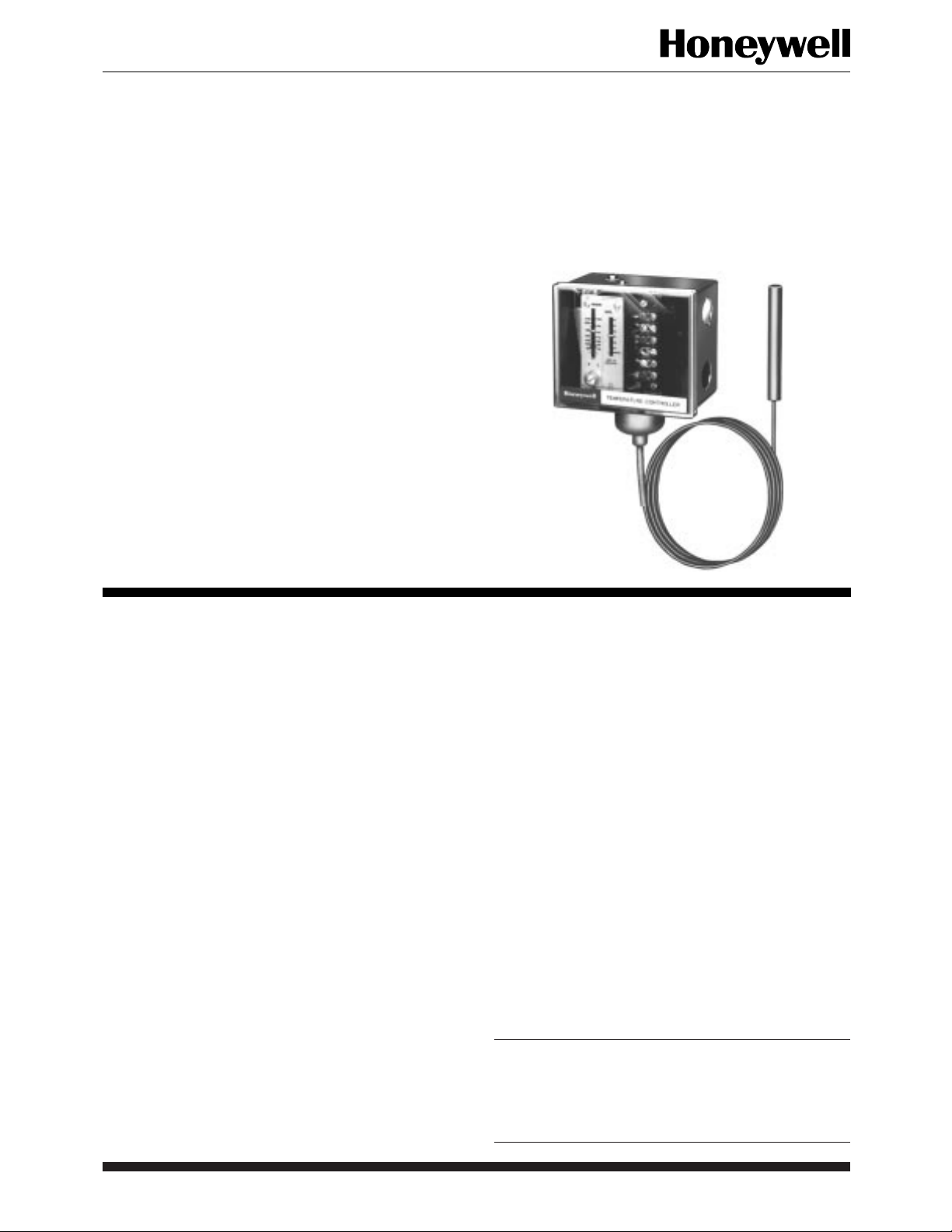
Proportional Temperature
Remote bulb temperature controllers for ducts,
tanks, boilers, pipes, and other heat exchangers.
These controllers are used with modulating motors
for proportional control of three-wire, low-voltage
valves or damper motors.
T915A-D,F,M,P
Controllers
■ T915M and T915P have spdt switches to control Series
20 motors. T915M controls at high or low end; T915P
controls at low end.
■ Controllers may be used to regulate temperatures of
either air or liquids.
■ All models ambient compensated.
■ Capillary tubing allows remote bulb mounting up to 20 ft
(6.0m) from controller case.
■ Temperature setting scale markings in both Fahrenheit
and Celsius.
■ Steel case with clear plastic cover makes settings readily
visible.
■ Surface mounting using two screws through back of case.
CONTENTS
Specifications .................................................2
Ordering Information.....................................2
Installation .....................................................4
Operation .......................................................6
Settings and Adjustments................................6
1 60-2201—7S. M. • Rev. 10-94 • ©Honeywell Inc. 1994 • Form Number 60-2201—7
Page 2
T915A-D,F,M,P
SPECIFICATIONS • ORDERING INFORMATION
Specifications
MODELS (also refer to Table 1):
T915A: One potentiometer for controlling a modulating
motor. Nonadjustable throttling range.
T915B: Two potentiometers for controlling two mod-
ulating motors in unison or in sequence, factory set for
unison control. Nonadjustable throttling range.
T915C: One potentiometer for controlling a modulating
motor. Adjustable throttling range.
T915D: Two potentiometers for controlling two modu-
lating motors in unison. Adjustable throttling range.
T915F: Two potentiometers for controlling two mod-
ulating motors in sequence. Adjustable deadspot between potentiometers and adjustable throttling range.
T915M and T915P: One potentiometer and Series 20
contacts for controlling one modulating motor and one
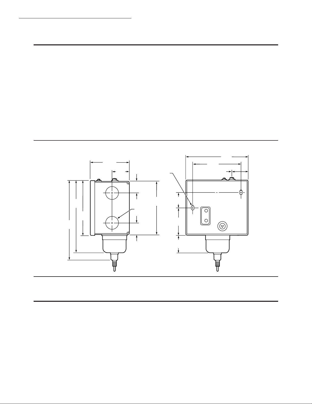
Fig. 1—Mounting dimensions in in. (mm).
2-3/4 (70)
1-1/16
(27)
5-1/32
(128)
3-7/8
(98)
5-1/2
(140)
13/16
(21)
7/8 (22.2) DIA.
13/16
(21)
Series 20 motor or relay in sequence on a temperature
rise. The Series 20 contacts on the T915M operate
above the throttling range and the Series 20 contacts
on the T915P operate below the throttling range. Both
models have nonadjustable throttling ranges and differentials.
BULB HOLDER: Furnished with copper elements.
RANGES: Fahrenheit and Celsius on the same scaleplate.
TEMPERATURE SETTING: Screws on top of controller
provide main and differential adjustment.
ELECTRICAL RATING: Low voltage ac only.
POTENTIOMETER: Standard 135 ohm. Available with
280 ohm potentiometer in some models; see Table 1.
FINISH: Gray enamel.
DIMENSIONS: See Fig. 1.
4-1/2
(114)
3-13/32
MOUNTING HOLE
KNOCKOUTS (2)
3-23/32
(95)
1-3/32
(28)
1-13/16
(46)
(87)
1-5/32
(29)
1-3/16
(30)
M7358
Ordering Information
When purchasing replacement and modernization products from your TRADELINE® wholesaler or distributor, refer to the TRADELINE
Catalog or price sheets for complete ordering number, or specify—
1. Order number. 4. Capillary length.
2. Scale range. 5. Accessories, if desired.
3. Bulb size.
If you have additional questions, need further information, or would like to comment on our products or services, please write or phone:
1. Your local Home and Building Control Sales Office (please check the white pages of your phone directory).
2. Home and Building Control Customer Logistics
Honeywell, Inc., 1885 Douglas Drive North
Minneapolis, Minnesota 55422-4386 (612) 951-1000
In Canada—Honeywell Limited/Honeywell Limitée, 740 Ellesmere Road, Scarborough, Ontario M1P2V9. International Sales and
Service Offices in all principal cities of the world. Manufacturing in Australia, Canada, Finland, France, Germany, Japan, Mexico,
Netherlands, Spain, Taiwan, United Kingdom, U.S.A.
®
60-2201—7 2
Page 3

T915A-D,F,M,P
SPECIFICATIONS
ACCESSORIES:
1. 33312B Knurled Knob for finger adjustment of temp-
erature setpoint.
2. 311266D Bulb Holder for mounting sensing bulb in an
3. Immersion well assemblies or pressure fittings—see
appropriate Honeywell specification or TRADELINE
Catalog to order. Wells available in copper and stainless
steel.
air duct (furnished with some models).
TABLE 1—T915 TEMPERATURE CONTROLLER MODELS.
Maximum
Model
Number °F °C °F °C °F °C ft m in. mm Fill
T915A 15 to 90 -9 to +32 3,
T915B 15 to 90 -9 to +32 3,
T915C 15 to 90 -9 to +32 7 to 38 3.9 to
T915C 15 to 90 -9 to +32 7 to 38 3.9 to
T915C 15 to 90 -9 to +32 7 to 38 3.9 to
T915C 15 to 90 -9 to +32 7 to 38 3.9 to
T915C 15 to 90 -9 to +32 7 to 38 3.9 to
T915C 80 to 210 27 to 99 6 to 32 3.3 to
T915C 80 to 120 27 to 99 6 to 32 3.3 to
T915D 15 to 90 -9 to +32 7 to 38 3.9 to
T915D 15 to 90 -9 to +32 7 to 38 3.9 to
T915D 105 to
T915F 15 to 90 -9 to +32 8 to 52 4.4 to
T915F 15 to 90 -9 to +32 8 to 52 4.4 to
T915Me15 to 90 -9 to +32 3,
T915M 105 to
T915Pf15 to 90 -9 to +32 3,
a
Throttling range adjustable except where noted.
b
LTD—Limited-fill elements require that controller, including all of capillary (except bulb and adjacent 4 in. [102 mm] of capillary), be in an ambient
temperature at least 10°F (5.6°C) above bulb temperature. These controllers become inoperative when temperature of controlled air or liquid is above 120°F
(49°C).
HT—High-temperature-fill elements require that controller and all of capillary (except bulb and adjacent 4 in. [102 mm] of capillary) be in an ambient
temperature at least 10°F (5.6°C) below bulb temperature.
CA—Cross ambient.
c
Wiper moves toward W on temperature rise.
d
Factory set for unison control.
e
Spdt contacts operate approximately 1°F (0.6°C) above the throttling range (0.5°F [0.3°C] differential at midscale).
f
Spdt contacts operate approximately 1°F (0.6°C) below the throttling range (0.5°F [0.3°C] differential at midscale).
Scale
Range
40 to 105 9 to 39 5.0 to
220
40 to 105 3,
220
fixed
fixed
fixed
fixed
fixed
Throttle
Range
c
f
c
c
c
a
1.7,
fixed
1.7,
fixed
21.1
21.1
21.1
21.1
21.1
17.8
17.8
21.1
21.1
21.7
28.9
28.9
1.7,
fixed
1.7,
fixed
1.7,
fixed
Bulb
Temp -
erature
200 93 5 1.5 1/2 x 4 13 x 102 LTD 135 1 modulating
c
130 54 5 1.5 11/16 x
f
200 93 11 3.4 1/2 x 4 13 x 102 LTD 135 1 modulating
200 93 20 6.1 1/2 x 4 13 x 102 LTD 135
130 54 5 1.5 11/16 x
130 54 15 4.5 11/16 x 7 17 x 177 CA 135
130 54 5 1.5 11/16 x
230 110 5 1.5 1/2 x 4 13 x 102 HT 135
230 110 20 6.1 1/2 x 4 13 x 102 HT 135
130 54 5 1.5 11/16 x
130
240 116 5 1.5 1/2 x 4 13 x 102 HT 135
130 54 5 1.5 11/16 x
130
130 54 5 1.5 11/16 x
c
240
c
130 54 5 1.5 11/16 x
c
Capillary
(Copper) Size of Bulb
54 20
54 20
116 5
6.1 11/16 x
6.1 11/16 x
1.5 1/2 x 4 13 x 102 HT 135 Series 20 motor
Type
17 x 368 CA 135 2 modulating
14-1/2
17x 368 CA 135
14-1/2
17 x 368 CA 280
14-1/2
17 x 368 CA 135 2 modulating
14-1/2
17 x 445 CA 135 unison
17-1/2
17 x 368 CA 135 2 modulating
14-1/2
17 x 445 CA 135 sequence
17-1/2
17 x 368 CA 135 1 modulating
14-1/2
17 x 368 CA 135
14-1/2
of
Potenti -
ometer
Resistance
b
(ohms) Controls
motor
motors in
unison or
sequence
motor
motors in
motors in
motor and 1
or relay
®
d
3 60-2201—7
Page 4

T915A-D,F,M,P
INSTALLATION
Installation
WHEN INSTALLING THIS PRODUCT…
1. Read these instructions carefully. Failure to follow
them could damage the product or cause a hazardous
condition.
2. Check the ratings given in the instructions and on
the product to make sure the product is suitable for your
application.
3. Installer must be a trained, experienced service
technician.
4. After installation is complete, check out product
operation as provided in these instructions.
CAUTION
Disconnect the power supply before connecting
wiring to prevent electrical shock and equipment
damage.
MOUNTING
Locate the bulb where it will sense the average tempera-
ture of the controlled air or liquid.
Mount the case and the bulb of these controllers within
2 ft (0.6m) above or below each other. If the case is more
than 2 ft (0.6m) above or below the bulb, the calibration can
change (Fig. 2). The controller case mounts on a wall or
panel using the two screws through the knockouts on the
rear of the case. Bulb mounts with a bulb holder, pressure
fitting or immersion well assembly.
When running the capillary tubing, avoid kinks by making sure all bends have at least 2 in. (51 mm) radius.
Kinking the tubing renders the controllers inoperable. Leave
any excess tubing coiled under the controller case.
A bulb holder for mounting the bulb in an air duct is
furnished with models having copper elements. If the installation requires a pressure tight fit, use a pressure fitting
(Figs. 3 and 4).
If the bulb is located in an agitated liquid, support it
firmly or protect it with a separable well (Fig. 5). Refer to
the TRADELINE® Catalog for more detailed information
on accessories.
Mount low temperature controller where the case and
the capillary tubing are always warmer than the bulb;
mount high temperature controllers where the case and
capillary tubing are colder than the bulb.
When these instructions are followed, ambient temperature will not affect temperature control point.
Fig. 2—Installation of control and sensing
element.
TANK OR
DUCT WALL
CAPILLARY TUBING
WASTE NUT
BULB
(CAPSULE)
PRESSURE
FITTING
Fig. 3—Assembly of pressure fitting.
1/2 IN. (13mm) PIPE THREAD FOR 1/2 IN. (13mm)CAPSULES
3/4 IN. (19mm) PIPE THREAD FOR 11/16 IN. (17mm) CAPSULES
BOILER PLUG
CAPILLARY TUBING
COMPOSITION DISK
(SLOTTED)
M7357
60-2201—7 4
PACKING NUT
SLOTTED WASHERS
ASSEMBLED IN PAIRS
THUS-
M7354
Page 5

T915A-D,F,M,P
INSTALLATION
Fig. 4—Use of bulb holder for mounting
sensing element in air duct application.
Dimensions in in. (mm).
THERMOMETER
BULB
14
ADJUSTABLE
CONTROLLER BULB
2-1/4 x 2-1/4 (57 x 57) APPROXIMATE
HOLE IN DUCT FOR INATALLATION
3-1/4
(83)
2-3/4
(70)
ACCESS
HOLE
1-5/8
(41)
3-1/4 (83)
1-3/8
(35)
RUBBER GROMET
NO. 8 SHEET METAL
MOUNTING SCREWS (2)
Fig. 5—Use separable well for mounting
sensing bulb in an agitated liquid.
PACKING
NUT
TUBING
COMPOSITION DISK
FITTING (INCLUDING WELL)
SLOTTED BRASS WASHERS (4)
(SLOTS 180 DEGREES APART)
FITTING
MINIMUM INSERTION LENGTH
APPROXIMATELY
4-3/4 IN. (121mm)
BULB
SPRING
CLIPS (2)
M7355
BULB
Fig. 6—Typical heating connections for T915A,C.
For cooling, reverse B and W at motor.
SERIES 90
MOTOR
R
W
B
T915A,C
1
POWER
SUPPLY
R
T
W
T
B
PROVIDE DISCONNECT MEANS AND
1
OVERLOAD PROTECTION AS REQUIRED.
Fig. 7—Typical connections for T915B,D and F.
POWER
SUPPLY
SERIES 90
MOTOR
1
R
W
B
R
T
W
T
B
PROVIDE DISCONNECT MEANS AND OVERLOAD
1
PROTECTION AS REQUIRED.
R
W
B
T915B,D,F
R
W
B
SERIES 90
MOTOR
T
T
POWER
SUPPLY
M7362
M7364
1
TUBING
SPRING CLIP
INSERTION LENGTH
APPROXIMATELY
3-3/8 IN. (86mm)
M7356
WIRING
Disconnect the power supply before connecting wiring
to prevent electrical shock and equipment damage. All
wiring must agree with local codes, ordinances, and regulations.
There are two 7/8 in. knockouts for 1/2 in. conduit on the
right side of the case. When wiring, refer to the instructions
packed with the motor or valve and the following typical
wiring hookups (Fig. 6 through 8). Refer to Fig. 9 for
internal schematics of T915 controllers.
NOTE: Connect B models, which control two motors or
valves in sequence on a temperature rise, so that the first
motor or valve to operate is connected to the front poten-
tiometer terminals (Fig. 7). Connect F models when used
in the above application so that the first operator is
connected to the rear potentiometer.
Fig. 8—Typical connections for T915M and P.
POWER
SUPPLY
SERIES 90
MOTOR
1
R
SERIES 20
TERMINALS
R
T
W
T
B
PROVIDE DISCONNECT MEANS AND OVERLOAD
1
PROTECTION AS REQUIRED.
W
B
R
W
B
T915M,P
R
W
B
SERIES 20
DEVICE
SERIES 90
TERMINALS
T
T
1
POWER
SUPPLY
M7363
5 60-2201—7
Page 6

T915A-D,F,M,P
INSTALLATION • OPERATION • SETTINGS AND ADJUSTMENTS
Fig. 9—Internal schematics of T915 temperature controllers.
BACK
POTENTIOMETER
R
W
B
T915A,C
FRONT
POTENTIOMETER
T915B,D,F T915M,P
Temperature changes at the remote sensing bulb cause a
pressure change within the bulb and capillary of the T915
Proportional Temperature Controller. This pressure change
is transmitted to the bellows inside the controller case that
operate the potentiometer wiper. Proportional control of a
valve or damper is obtained.
R
W
B
R
W
B
SERIES 20
CONTACTS
BACK
POTENTIOMETER
R
W
B
R
W
B
M7361
Operation
Operation of T915M and P models is the same except
that at the high or low end of the proportioning range
(depending on the model), an spdt switch is used to operate
a Series 20 system component.
Settings and Adjustments
TEMPERATURE SETTING
Set the main scale setting at the desired temperature on
all models except C,D, and F; set those models so the main
scale indicator is at the low end of the desired proportioning
range.
The T915B is factory set for simultaneous operation and
is adjustable to full sequence. Depending on the setting, the
first operator may complete its full cycle or any portion
before the second operator starts.
Adjustable proportional ranges (differentials) on
T915C,D, and F are additive to the main scale setting. The
T915D is designed for simultaneous operation and has no
sequence adjustment. The T915F is factory set for sequence operation and has a deadspot equal to about onethird of the proportional range. This deadspot cannot be
increased, but it can be set to zero or to a partial overlap.
The T915M and P have one potentiometer and a set of
Series 20 contacts for controlling one Series 90 operator
and a Series 20 motor or relay in sequence.
The T915M contacts operate above the proportioning
range about 1°F (0.6°C); the T915P contacts operate below the proportioning range. Both models have nonadjustable proportional ranges (Series 90) and differentials (Series 20).
Turn the adjustment screw (Fig. 10) until the indicator is
opposite the desired mark on the scaleplate.
Fig. 10—Internal view of T915F (see Specifications for differences between models).
TEMPERATURE
SETTING
INDICATOR
DIFFERENTIAL
(PROPORTIONAL
RANGE) SETTING
INDICATOR
TEMPERATURE
ADJUSTMENT SCREW
PROPORTIONAL RANGE
ADJUSTMENT SCREW
BELLOWS HOUSING
POTENTIOMETER
COIL(S)
SLIDING CONTACTS
WIRING TERMINALS
DEADSPOT
(ECCENTRIC)
ADJUSTMENT
SCREW
OPERATING LEVER
M7360
60-2201—7 6
Page 7

T915A-D,F,M,P
SETTINGS AND ADJUSTMENTS
PROPORTIONAL RANGE (Differential) SETTING
Refer to proportional range curve, Fig. 11.
1. If this graph covers the scale and proportional ranges
of your controller, refer to the graph and read as follows:
a. Locate the horizontal line that represents the desired
main scale temperature setting of the controller.
b. Locate the vertical line that represents the desired
proportional range setting.
c. Determine the point at which the lines intersect.
d. The relation of this point to the proportional range
setting curves, labeled at the top of the graph, deter-
mine the proportional range indicator setting. Thus, if
the point lies between curve A and curve B, turn the
proportional range adjustment screw (Fig. 10) until
the proportional range indicator is between A and B on
the scaleplate.
2. If the controller model being installed is not covered
by this graph, use a trial and error method:
a. Refer to the graph in Fig. 11.
b. Select a tentative setting by following steps 1.a through
1.d.
c. Run a test to determine the direction for further adjust-
ment.
NOTE: Too narrow a proportional range may make the sy-
stem unstable. Increase the range to stabilize the system,
remembering that increasing the proportional range also
increases offset (control point rise at very light load and
drop at very heavy load).
Fig. 11—Proportional range curve for T915
with 15°F to 90°F (minus 9°C to plus 32°C)
scale range.
PROPORTIONAL RANGE SETTING
F
C
MIN A
B
90
30
80
CDEF
ADJUSTMENT OF SEQUENCE
OPERATION (T915B)
1. For simultaneous operation, no adjustment is required.
2. (On a temperature rise, the front wiper sweeps a
portion of the active windings of its potentiometer before the
back wiper enters the active windings of its potentiometer.)
For operation with partial overlap of wiper travel, turn the
eccentric screw to the left an amount proportional to the
desired overlap of wiper travel. For example, if on a temperature rise, the back wiper is to enter its active windings after
the front wiper has swept one-half of its active windings, turn
the eccentric screw to the left one-half as far as it will go.
3. (On a temperature rise, the front wiper leaves the
active windings of its potentiometer as the back wiper
enters the active windings of its potentiometer.) For sequence operation, turn the eccentric screw to the left as far
as it will go.
4. For sequence operation with a deadspot equal to
one-third of the overall proportioning range, no adjustment is required.
5. For sequence operation without deadspot or with a
deadspot of less than one-third of the overall proportioning, turn the eccentric screw to the left. Turning the
eccentric screw three-fourths of its full travel to the left
will reduce the deadspot to zero. Turning the eccentric
screw less than three-fourths of its full travel will reduce
the deadspot proportionally.
6. (Front wiper enters the active windings of its potentiometer before the back wiper leaves the active windings
of its potentiometer.) For operation with partial overlap of
wiper travel, turn the eccentric screw to the left as far as it
will go.
70
20
60
50
10
40
0
30
MAIN SCALE SETTING – DEGREES
20
15
–10
01020304050
051015 20 25
PROPORTIONAL RANGE – DEGREES
F
C
M7365
7 60-2201—7
Page 8

By using this Honeywell literature, you agree that Honeywell will have no liability for any damages arising out of your use or
modification to, the literature. You will defend and indemnify Honeywell, its affiliates and subsidiaries, from and against any liability,
cost, or damages, including attorneys’ fees, arising out of, or resulting from, any modification to the literature by you.
Home and Building Control Home and Building Control Helping You Control Your World
Honeywell Inc. Honeywell Limited—Honeywell Limitée
1985 Douglas Drive North 740 Ellesmere Road
Golden Valley, MN 55422 Scarborough, Ontario
M1P 2V9
60-2201—7 8
Printed in U.S.A.
QUALITY IS KEY
 Loading...