

Page 1

T8624C,D (5-1-1 Day
Programming) Chr onotherm
III Fuel Saver Thermostats
The T8624C,D Chronotherm III Programmable Fuel Saver Thermostats provide automatic control of multistage heating/cooling systems and offer users the highest standard of
comfort and convenience available with energy
savings.
■ Different schedules may be selected for week-
days, Saturday and Sunday.
■ Can be programmed in hand (with batteries in-
stalled) or on wall to provide up to four tempera-
ture settings per day.
■ Large digital clock (liquid crystal display) indi-
cates continuous time, day, current period and
room temperature.
■ Adaptive Intelligent Recovery™ brings room tem-
perature to programmed temperature at pro-
grammed time, maximizing comfort and energy
savings.
■ Temperature control program maintains tempera-
ture within 1° F of setpoint.
■ Temporary program override available by using:
— WARMER and COOLER keys.
— SKIP next period key.
— CHANGE to last period key.
■ HOLD TEMP key provided for indefinite pro-
gram override (vacation/holiday).
■ Installer self-test and time delay override save
installation time.
■ SYSTEM light-emitting diode (LED) indicates
system is energized.
■ Models available with automatic or manual heat/
cool changeover.
■ Batteries included provide power to maintain
clock and memory during power failures.
■ Switching subbase with wiring terminals included.
■ Powered directly from control transformer, re-
quiring an extra (24V) wire to thermostat.
■ Fan operation switch to select either independent
or direct thermostat control of fan in heating
included on back of select models.
CONTENTS
Specifications .................................................2
Ordering Information.....................................2
Selection/Application .....................................4
Installation .....................................................5
Checkout.......................................................11
Programming the Thermostat ......................14
Operating the Thermostat ............................18
Troubleshooting ...........................................21
Glossary .......................................................22
®
C.H. • 9-93 • ©Honeywell Inc. 1993 • Form Number 68-0134
1 68-0134
Page 2

T8624C,D
SPECIFICATIONS • ORDERING INFORMATION
Specifications
IMPORTANT: The specifications given in this publi-
cation do not include normal manufacturing tolerances. Therefore, this unit may not exactly match
the listed specifications. Also, this product is tested
under closely controlled conditions, and some minor differences in performance can be expected if
those conditions are changed.
TRADELINE® MODELS
TRADELINE models (see Table 1) are selected and
packaged to provide ease of stocking and handling
and also maximum replacement value.
LIGHT-EMITTING DIODE (LED): SYSTEM LED
lights during thermostat ON cycle.
VOLTAGE RATING: 15 to 30 Vac.
CURRENT RATING: 1.6A maximum total per stage.
OPERATING HUMIDITY RANGE: 5 to 90 percent
relative humidity, noncondensing.
OPERATING AMBIENT TEMPERATURE RANGE:
40° F to 110° F [4° C to 43° C].
TABLE 1—TRADELINE MODELS.
Thermostat
Model
Number
T8624C 2 1 Auto HEAT-AUTO-COOL-OFF ON-AUTO Multistage
T8624D 2 2 Auto HEAT-AUTO-COOL-OFF ON-AUTO Multistage
T8624D 2 2 Manual HEAT-OFF-COOL ON-AUTO Multistage
Stages Changeover Switching
Heat Cool
Type
SETPOINT RANGE: 45° F to 88° F [7° C to 31° C].
CALIBRATION: Self-calibrating thermostat and
thermometer to ±1° F.
SHIPPING TEMPERATURE: -20° F to +120° F [-29° C
to +49° C].
CYCLES PER HOUR ADJUSTMENT:
Heating: First stage of 2-stage heat models—fixed at
3 cph. Second stage of 2-stage heat models or heat
stage of single-stage heat models—factory-set at
6 cph; field-adjustable to 1,3,6 or 9 cph.
Cooling: Factory-set at 3 cph (not field adjustable);
minimum off-time of five minutes.
FINISH: Beige matte with decorative brushed metal
faceplate or Premier White™.
DIMENSIONS: Thermostat (mounted on subbase)—7 in.
[178 mm] long, 5-5/16 in. [135 mm] high, 1-3/4 in.
[44 mm] deep. See Fig. 1 for subbase dimensions.
TYPICAL KEYPAD: See Fig. 2.
ACCESSORIES:
TG586A Locking Cover.
TG512 Versaguard™ Universal Thermostat Guard.
System Fan
Application
Ordering Information
When purchasing replacement and modernization products from your TRADELINE® wholesaler or your distributor, refer to the
TRADELINE Catalog or price sheets for complete ordering number, or specify—
1. Model number. 3. System, fan switching desired.
2. Number of heat and cool stages desired. 4. Application.
If you have additional questions, need further information or would like to comment on our products or services, please write or
phone:
1. Your local Honeywell Home and Building Control Sales Office (check white pages of your phone directory).
2. Home and Building Control Customer Satisfaction
Honeywell Inc., 1885 Douglas Drive North
Minneapolis, Minnesota 55422-4386 (612) 951-1000
In Canada—Honeywell Limited/Honeywell Limitee, 740 Ellesmere Road, Scarborough, Ontario M1P 2V9. International
Sales and Service offices in all principal cities of the world. Manufacturing in Australia, Canada, Finland, France, Germany,
Japan, Mexico, Netherlands, Spain, Taiwan, United Kingdom, U.S.A.
2
Page 3
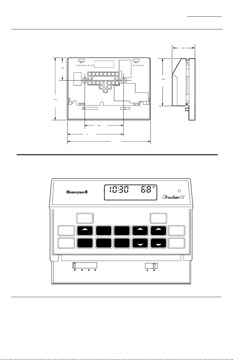
Fig. 1—T8624 Subbase mounting dimensions in in. [mm].
13
1
16
[46]
5
5
16
[135]
5
3 [83]
16
3
4 [121]
4
M5181A
7 [179]
Fig. 2—Typical thermostat keypad.
4
[104]
T8624C,D
SPECIFICATIONS
31
1
32
[50]
3
32
SET
PRESENT
DAY/TIME
HOLD
TEMP
PROGRAM
HEAT/COOL
HEAT AUTO
RUN
DAY
SET
COOL
AM
WED
LEAVE
PERIOD
WAKE
SLEEP
OFF
LEAVE
RETURN
HEAT ON
TEMPERATURE
TIME
AHEAD
BACK COOLER
ON AUTO
ROOM
PRESENT
SETTING
WARMER
SYSTEM
SKIP
NEXT
PERIOD
CHANGE
TO LAST
PERIOD
FAN
M2998
3 68-0134
Page 4

T8624C,D
SELECTION/APPLICATION
Selection/Application
The T8624 Thermostat uses the latest microelectronic design and control technology to provide home
and building owners with the highest level of comfort
available and optimal energy savings in a package that is
easy to use and easy to live with.
The following section is a guide to selection and
application of the best thermostat to meet individual
needs.
PROGRAMMING
Does the thermostat selected accommodate the
customer’s daily schedule, lifestyle or work schedule?
Device Programming
T8624C,D 5-1-1 (Mon-Fri,
Sat, Sun)
T8621A,C,D 7-day (each
day different)
T8600,01,02,03* 5-1-1 (Mon-Fri,
Sat, Sun)
The choices are:
*Model not currently available to control multistage
equipment.
IF NEW CONSTRUCTION APPLICATION, CONSIDER:
• Equipment type (see manufacturer specifications).
—Staging required.
—System switching required.
—Fan switching required.
• Control wiring—number of conductors required
to operate equipment and thermostat.
IMPORTANT: The T8624 requires an additional con-
ductor to transformer common to provide continuous 24V power for thermostat operation.
IF RETROFIT/REPLACEMENT APPLICATION,
CONSIDER:
• Equipment requirements.
— Staging (heat stages, cool stages).
— System switching (manual: HEAT-OFF-COOL;
automatic: HEAT-AUTO-COOL-OFF). Emergency heat for heat pump application not provided on T8624.
Daily
Temperature
Selection
4 heat and
4 cool
4 heat and
4 cool
4 heat and
4 cool
programmming and the override features that will best
suit the application? The choices are:
SINGLE-STAGE HEAT PUMPS
one option is to use a T8624C or D (see Fig. 8).
ing programmable thermostat. The T8624D is a two-
stage heating, two-stage cooling programmable thermostat. What both thermostats have in common is separate
W1 and W2 (first and second stage heat) terminals. In
both cases, the W1 can be used for changeover in heating.
stage heating and first-stage cooling energized through
the Y terminal), simply jumper Y1 and W1.
cause the compressor to cycle on and off during recovery.
cool are set for hot water systems, the second stage of the
T8624 must be adjusted. Turn the cycle rate adjustment
screws to the hot water setting on both the T8624C and
D to achieve the cycle rate appropriate for heat pumps.
normally closed relay.
stage heat pumps.
— Fan switching; does fan come on automatically
from thermostat on cooling only (typical gas/
oil heating), or on call for cool and heat (typical
electric heat with single speed fan)?
• Existing wiring
— Are there enough conductors to operate the equip-
ment and the thermostat? Can a new cable be
pulled?
IMPORTANT: The T8624 requires an additional con-
ductor to transformer common to provide continuous 24V power for thermostat operation.
SECURITY
Does the thermostat selected provide access to
Access
Free access to
programming
and adjustment/
override.
Restricted
access to
device.
If home/building owner has a single-stage heat pump,
The T8624C is a two-stage heating, one-stage cool-
For single-stage compressor applications (both first-
Note that the recovery algorithm of the T8624 may
Although the cycle rate for the first stages of heat and
If changeover is utilized in the cooling mode, apply a
The above application should be used only on single-
Typical
Application Device
Home or
owner-occupied
commercial
building.
Public
building.
T8624A,C,D
T8624 with
TG512 Locking
Guard or
TG586A
Locking Cover.
4
Page 5
RECYCLING NOTICE
If this control is replacing a control that contains
mercury in a sealed tube, do not place your old control in
the trash. Contact your local waste management authority for instructions regarding recycling and the proper
disposal of your old control.
If you have any questions, call Honeywell Inc. at 1800-468-1502.
COMPATIBILITY
The T8624 Thermostats will replace most heating/
cooling system thermostats. As long as ac power is
continuously available to the transformer, the thermostat
will be compatible with any low-volt control system.
IMPORTANT: The T8624 requires an additional con-
ductor to transformer common to provide continuous 24V power for thermostat operation.
WHEN INSTALLING THIS PRODUCT…
1. Read these instructions carefully. Failure to follow
them could damage the product or cause a hazardous
condition.
2. Check the ratings given on the product to make
sure the product is suitable for your application.
3. Installer must be a trained, experienced service
technician.
4. Allow thermostat to warm to room temperature
before operating.
5. After installation is complete, check out product
operation as provided in these instructions.
T8624C,D
INSTALLATION
Installation
or disconnects. Remove any existing wallplate or subbase from wall. To avoid miswiring later, label each
wire color with the letter or number on the wiring terminal as the wire is removed.
NEW INSTALLATION
Run cable to a hole at the selected wall location for the
thermostat, and pull about 3 in. [76 mm] of wire through
the opening. Color-coded, 18-gauge thermostat cable with
at least one conductor for each wiring terminal is recommended. Good service practice recommends selecting
cable with one or two more conductors than the immediate application requires.
MOUNTING SUBBASE
IMPORTANT: Before mounting, set the system switch
to the OFF position.
NOTE: The subbase does not require leveling for proper
operation, but only for appearance.
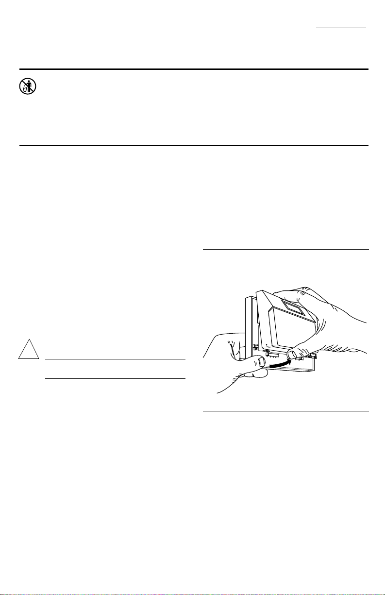
Fig. 3—Removing thermostat from subbase.
CAUTION
!
Disconnect power supply to prevent electrical
shock or equipment damage.
LOCATION
Install thermostat and subbase about 5 ft [1.5m] above
the floor in an area with good air circulation at room
temperature.
Do not install thermostat where it may be affected by:
— drafts or dead spots behind doors, in corners or
under cabinets.
— hot or cold air from ducts.
— radiant heat from sun or appliances.
— concealed pipes and chimneys.
— unheated (uncooled) areas such as an outside wall
behind the thermostat.
REPLACING AN EXISTING THERMOSTAT
Turn off thermostat power at furnace or boiler. A twotransformer system may require turning off two switches
H
E
A
T
A
U
T
O
C
O
O
L
O
F
F
F
A
N
O
N
A
U
T
O
M 844
Remove thermostat from subbase (Fig. 3).
Mount the subbase directly onto the wall with the
screws and anchors included. If drywall construction,
use plastic anchors. Use the subbase as a template, and
with a pencil, mark the two mounting screw positions
(Fig. 4). Use
3/16 in. bit to drill holes for anchors. Gently tap anchors
into holes until they are flush with the wall surface.
Thread wires through the center opening of the subbase.
Then mount the subbase using the two screws provided.
Gently tighten the screws, level the top surface of the
subbase, and securely tighten the screws.
5 68-0134
Page 6
T8624C,D
INSTALLATION
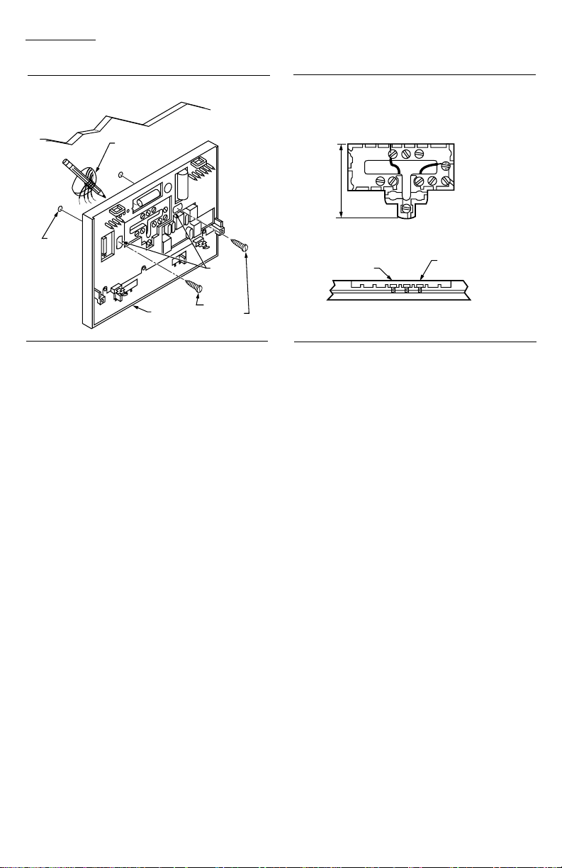
Fig. 4—Mounting subbase on wall.
WALL
WIRES THROUGH
WALL OPENING
WALL
ANCHORS
(2)
MOUNTING
HOLES
SUBBASE
MOUNTING
SCREWS (2)
M846
WIRING
All wiring must comply with local electrical codes
and ordinances.
Disconnect power before wiring to prevent electrical
shock or equipment damage.
The shape of the terminal barrier permits insertion of
straight or conventional wraparound wiring connections.
Either method is acceptable.
Push excess wire back into the hole, and plug the hole
with nonhardening caulk, putty or insulation to prevent
drafts from affecting thermostat operation.
NOTE: Restrict wiring to the recessed area surrounding
the terminals (Fig. 5) to assure thermostat/subbase
contact.
Refer to Figs. 6-8 for typical hookups of subbase and
thermostat.
ADJUSTING CYCLE RATE
To customize the thermostat cycling performance to
various types of heating equipment, cycle rate adjustment screws are provided on the back of the thermostat
to provide optimum room temperature control.
NOTE: Most applications will not require a change in
cycle rate.
The room air temperature will normally vary slightly
from the comfort temperature setting with the cycling of
the furnace or air conditioner.
The heating cycle rate of this thermostat is factory-set
for gas/oil warm air heating. The cooling cycle rate is
factory-set and cannot be adjusted. The heating cycle
rate can be adjusted by turning one or both cycle rate
adjustment screws located on the back of the thermostat.
Fig. 5—Restrict wiring to recessed area
surrounding terminals.
FOR STRAIGHT
INSERTION –
STRIP 5/16 in. [8 mm]
FOR WRAPAROUND –
RESTRICT
WIRING TO
THIS AREA
FRONT VIEW OF
TERMINAL AREA
WIRING TO BE BELOW
THIS SURFACE
CROSS-SECTIONAL VIEW OF
TERMINAL AREA
STRIP 7/16 in. [11 mm]
TOP SURFACE
OF SUBBASE
M 847
In multistage heat systems, the cycle rate adjustment
applies to the highest stage of heat only. Screws should
be backed out about one-half to one turn, or be turned in
until tight. See Fig. 9.
TIME/TEMPERATURE CONVERSION
(SOME MODELS)
The display readout may be converted between 12
and 24 hour clock or °C and °F using screws 2A and 2B
as indicated in Fig. 9.
FAN OPERATION OPTION SWITCH
(SELECT MODELS ONLY)
Select models include a fan operation option switch
on the subbase that is visible before the thermostat is
mounted on the subbase. The switch should be in electric
heat position for electric heating systems that do not
have independent fan control.
INSTALLING BATTERIES
Three AAA alkaline batteries are included to provide
backup to prevent program loss in case of power outage.
Install batteries in back of thermostat as shown in Fig.
10.
Without battery backup, the program will remain
about 30 seconds in event of power loss.
IMPORTANT: When batteries are first installed, the
display will flash 1:00 PM and 32°. The temperature will stay at 32
°
F until the thermostat is
powered from the system wiring.
When the batteries are low, the display will flash
REPL BAT. Homeowner will have 20-30 seconds to
install new batteries after removing old batteries from
back of thermostat. After 20-30 seconds, it will be necessary to reprogram. REPL BAT indication will disap-
6
Page 7
T8624C,D
INSTALLATION
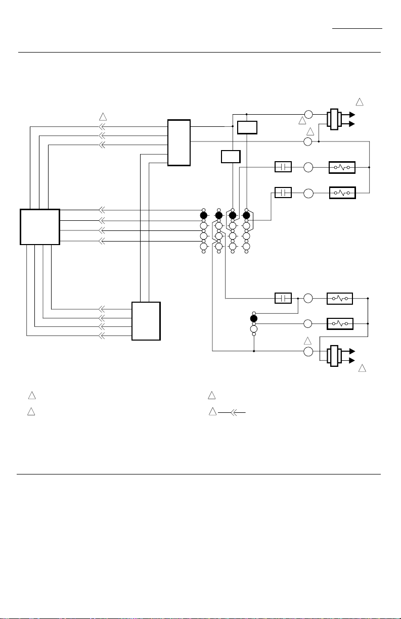
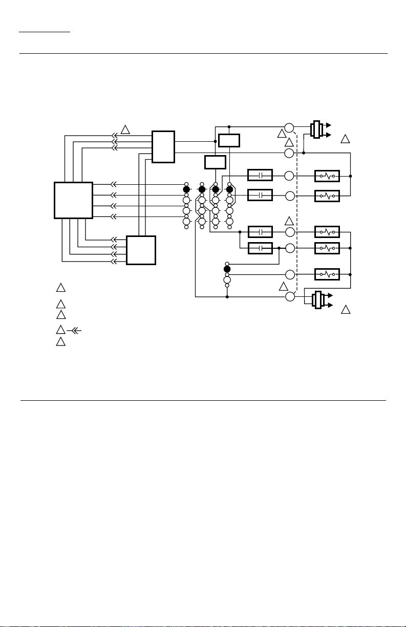
Fig. 6—T8624C 2-stage heat/1-stage cool thermostat with HEAT-AUTO-COOL-OFF system and AUTO-ON
fan switching.
HEATING
TRANSFORMER
R
2
3
C
W1
W2
Y1
G
2
RC
HEAT RELAY 1
HEAT RELAY 2
COOLING
CONTACTOR
FAN RELAY
COOLING
TRANSFORMER
THERMOSTAT
LOGIC CIRCUIT
4
POWER
SUPPLY
SYSTEM
SWITCH
SUBBASE
LOGIC/
CONTROL
CIRCUIT
HIGH
LIMIT
HIGH
LIMIT
FAN
SWITCH
HEAT 1
HEAT 2
HEAT
AUTO
COOL
OFF
COOL
AUTO
ON
1
L1
(HOT)
L2
L1
(HOT)
L2
1
1
POWER SUPPLY. PROVIDE DISCONNECT MEANS AND OVERLOAD
PROTECTION AS REQUIRED.
2
FOR SINGLE TRANSFORMER SYSTEM JUMPER R AND RC.
3
NOMINAL 24 Vac POWER MUST BE PRESENT BETWEEN R AND C FOR
THERMOSTAT OPERATION.
4
DENOTES THERMOSTAT TO SUBBASE INTERCONNECTION.
M5233
7 68-0134
Page 8
T8624C,D
INSTALLATION
Fig. 7—T8624D 2-stage heat/2-stage cool thermostat with HEAT-AUTO-COOL-OFF system and AUTO-ON
fan switching.
4
POWER
SUPPLY
THERMOSTAT
LOGIC
CIRCUIT
SUBBASE
LOGIC/
CONTROL
CIRCUIT
1
POWER SUPPLY. PROVIDE DISCONNECT MEANS
AND OVERLOAD PROTECTION AS REQUIRED.
FOR SINGLE TRANSFORMER SYSTEM, JUMPER R AND RC.
2
NOMINAL 24 Vac POWER MUST BE PRESENT BETWEEN
3
R AND C FOR THERMOSTAT OPERATION.
DENOTES THERMOSTAT TO SUBBASE INTERCONNECTION.
4
AVAILABLE ON T8624D MODELS ONLY.
5
HEAT
AUTO
COOL
OFF
SYSTEM
SWITCH
HIGH
LIMIT
FAN
SWITCH
AUTO
R
HEAT 1
HEAT 2
COOL 2
COOL 1
2
W1
2
3
C
W2
5
Y2
Y1
G
RC
COOLING
TRANSFORMER
HIGH
LIMIT
ON
L1
(HOT)
L2
HEATING
TRANSFORMER
HEAT RELAY 1
HEAT RELAY 2
COOLING
CONTACTOR 2
COOLING
CONTACTOR 1
FAN RELAY
L1
(HOT)
L2
M3765
1
1
8
Page 9

T8624C,D
INSTALLATION
Fig. 8—T8624D 2-stage heat/2-stage cool thermostat with HEAT-OFF-COOL system and AUTO-ON fan
switching; auto fan on heat and cool; convertible to auto fan on cool only.
L1
(HOT)
1
HEATING
TRANSFORMER
HEAT 1
HEAT 2
COOL 2
R
4
C
W1
W2
B
HEATING DAMPER OR
CHANGEOVER RELAY
COOLING DAMPER OR
CHANGEOVER RELAY
O
Y2
Y1
G
RC
COOLING
TRANSFORMER
STAGE 1
HEAT RELAY
STAGE 2
HEAT RELAY
STAGE 2
COOLING RELAY
STAGE 1
COOLING RELAY
FAN RELAY
3
1
5
THERMOSTAT
LOGIC CIRCUIT
POWER SUPPLY. PROVIDE DISCONNECT MEANS AND OVERLOAD
1
PROTECTION AS REQUIRED.
FOR GAS OR OIL APPLICATIONS OR ELECTRIC HEAT APPLICATIONS
2
WHERE THE FAN OPERATION IS CONTROLLED INDEPENDENTLY OF
THE THERMOSTAT (AUTO FAN OPERATES WITH Y1 ONLY), TWO
TRANSFORMERS MAY BE USED. SET SWITCH TO NONELECTRIC
POSITION.
SUBBASE
LOGIC/
CONTROL
CIRCUIT
POWER
SUPPLY
3
ELECTRIC
NON-ELECTRIC
2
HEAT
OFF
COOL
FOR ELECTRIC HEAT APPLICATIONS (AUTO FAN OPERATES WITH W1
3
AND Y1), USE ONLY ONE TRANSFORMER; JUMPER R AND RC. SET
SWITCH TO ELECTRIC POSITION.
NOMINAL 24 VAC POWER MUST BE PRESENT BETWEEN R AND C FOR
4
THERMOSTAT OPERATION.
5
HIGH
LIMIT
FAN
OPERATION
SWITCH
SYSTEM
SWITCH
FAN
SWITCH
AUTO
ON
HIGH
LIMIT
COOL 1
DENOTES THERMOSTAT TO SUBBASE INTERCONNECTION.
L1
(HOT)
L2
L2
M1016D
9 68-0134
Page 10

T8624C,D
INSTALLATION
Fig. 9—Cycle rate adjustment.
1A
1B
1
2A 2B
CYCLES
SYSTEM
1A
1B
OUT 1/2
GRAVITY
AIR/WATER
HOT
WATER
GAS/OIL
WARM AIR
ELECTRIC
WARM AIR
1 SCREWS 2A, 2B AVAILABLE ON SOME MODELS ONLY.
OUT 1/2
TO 1 TURN
TO 1 TURN
OUT 1/2
TO 1 TURN
IN IN
(FACTORY SETTING)
OUT 1/2
IN
TO 1 TURN
IN
PER HOUR
1
3
6
9
TIME/TEMP
DISPLAY
24 HR
12 HR
o
C
o
F
2A
IN
OUT 1/2
TO 1 TURN
2B
IN
OUT 1/2
TO 1 TURN
M311A
pear when thermostat is mounted back on the subbase.
IMPORTANT: For proper thermostat operation, al-
ways replace dead batteries with new alkaline
batteries. We recommend Energizer® batteries.
If batteries are completely dead, the display will go
blank when the thermostat is removed from the subbase.
Fig. 10—Battery placement.
POWER OUTAGES
Backup batteries will hold the programming and keep
the display on during most power outages. Once the
power is restored, the system will resume normal operation.
After replacing the batteries, reprogramming will be necessary.
BATTERY PLACEMENT
(NOTE CORRECT PLUS
AND MINUS DIRECTION)
M 372A
If the display goes off when power is lost, either the
backup batteries need to be replaced or are not installed.
When power is restored, the display will flash 1:00 PM
as a reminder to reprogram.
MOUNTING THE THERMOSTAT
With system switch set to OFF, hang the thermostat
on the tabs at the top of the subbase (Fig. 11A). Swing
down and press on lower edge until thermostat snaps in
place (Fig. 11B). Open cover and tighten the captive
mounting screws (Fig. 11C).
SETTING DAY AND TIME
Restore 24V power to the thermostat. When power is
applied to the thermostat, the display will read 1:00 PM
and room temperature. It will go off for a few seconds,
then begin to flash on and off. Set present day and time.
SET
PRESENT
Press .
DAY/TIME
Press to set the current day. Each press of
the DAY key advances the display one day.
DAY
Press TIME or to set the current time.
AHEAD
BACK
If the display will not come on:
— Check the mounting of the thermostat to the sub-
base. If loose or misaligned, remove thermostat
and reinstall on the subbase, making sure it is
firmly attached.
— Check to see that heat or cool system power is on.
— Check voltage between R and C; it should be 24 to
30 Vac.
10
Page 11

Fig. 11—Mounting thermostat on subbase.
T8624C,D
INSTALLATION • CHECKOUT
A.
N
A
F
O
T
U
A
N
O
F
F
O
L
O
O
C
O
T
U
A
T
A
E
H
C.
P
R
D
A
H
T
HEATING
Move the system switch to HEAT and the fan switch
to AUTO. Press WARMER key until the setting is about
10° F [6° C] above room temperature. Heating should
start (both stages if multistage), and the fan should run
(may be a short delay on forced air systems). Press
COOLER key until the setting is about 10° F [6° C]
below room temperature. The heating equipment should
shut off, followed by the fan.
NOTE: On an AUTO changeover thermostat, the cool-
ing temperature must be set at least 3° F [2° C] above
the heating temperature, or display will flash.
COOLING
CAUTION
!
Do not operate cooling if outdoor temperature
is below 50° F [10° C]. Refer to manufacturer
recommendations.
N
O
M
N
R
TU
E
R
R
U
N
P
R
O
G
R
A
M
P
E
R
IO
D
S
E
T
E
S
E
N
T
W
A
K
E
L
E
A
V
E
D
A
Y
Y
/T
IM
E
O
L
D
S
E
T
S
L
E
E
P
R
E
T
U
R
E
M
P
N
H
E
A
T
/
C
O
O
L
B.
PM
MON
RETURN
HEAT ON
SYSTEM
M
P
N
O
T
A
E
H
T
E
M
P
E
R
A
T
U
R
E
P
R
E
S
E
N
T
S
E
T
T
IN
G
T
I
M
E
S
K
IP
N
E
X
T
A
H
E
A
D
W
A
R
M
E
R
P
E
R
IO
D
C
H
A
N
G
E
B
A
C
K
C
O
O
L
E
R
T
O
L
A
S
T
P
E
R
I
O
D
Checkout
Move the system switch to COOL and the fan switch
to AUTO. Press COOLER key until the setting is about
10° F [6° C] below room temperature. The cooling
equipment and fan should start (both stages if multistage). Press WARMER key until the setting is about
10° F [6° C] above room temperature. The cooling
equipment and fan equipment should stop.
NOTE: On an AUTO changeover thermostat, the heat-
ing temperature must be set at least 3° F [2° C] below
the cooling temperature, or display will flash.
FAN
Move the system switch to OFF, and the fan switch to
ON. The fan should run continuously. When the fan
switch is in the AUTO position, the fan operates directly
with the thermostat call for cooling and also with the
SYSTEM
A
U
T
O
M3764
NOTE: When cooling setting is changed, thermostat
will wait up to five minutes before turning on the
cooling equipment. This delay is to protect the compressor.
11 68-0134
Page 12

T8624C,D
CHECKOUT
REPL
AM
BAT
This
Key
CHANGE
TO LAST
PERIOD
SKIP
NEXT
PERIOD
PRESENT
SETTING
PRESENT
SETTING
PM
Look For This Response
Key
Down Key Released
07 Blank
15 Blank
15 1st stage cooling,
SUN MON TUE WED THU FRI SAT COOL ON HEAT ON
WAKE LEAVE RETURN SLEEP TEMPORARY
System Press
Switch
Position
OFF 03 Blank
COOL or
AUTO
(with fan in
AUTO) 15 2nd stage cooling
PRESENT
SETTING
PRESENT
SETTING
PRESENT
SETTING
15 2nd stage cooling
15 1st stage cooling,
SET
PT
M410C
RUN
PROGRAM
fan and SYSTEM
LED on.
also on.
off.
fan and SYSTEM
LED off.
NOTE: If single-stage cooling system, press key twice
instead of four times; once to turn on cooling, fan
and SYSTEM LED, second time to turn off.
(continued)
System Press
Switch
Position
OFF 06 Blank
(CHECK
EACH
This
Key
WARMER
COOLER
AHEAD
LEAVE
RETURN
WAKE
Look For This Response
Key
Down Key Released
02 Blank
05 Blank
BACK
04 Blank
01 Blank
00 Blank
12 See note A
A
POSITION)
OFF 08 Blank
SLEEP
13 Microprocessor
mask no. and
revision no.
09 Blank
14 Blank
14 1st stage heating
and SYSTEM
LED on.
14 2nd stage heating
also on.
14 2nd stage heating
off.
14 1st stage heating
and SYSTEM
HEAT or
AUTO
DAY
SET
HEAT/COOL
SET
PRESENT
DAY/TIME
SET
PRESENT
DAY/TIME
1
SET
PRESENT
DAY/TIME
SET
PRESENT
DAY/TIME
SET
PRESENT
DAY/TIME
LED off.
NOTE: If single-stage heating system, press key twice
instead of four times; once to turn on heating and
SYSTEM LED, second time to turn off.
OFF 10 Blank
HOLD
TEMP
RUN
PROGRAM
11 Normal operating
display.
END SELF-TEST
12
Page 13

T8624C,D
CHECKOUT
Cycle Rate Setting (cph at 50% on
time for stage 1 on 1-heat models,
First Digit
stage 2 on 2-heat models)
01
13
29
36
Third
Digit
Manual or Auto
Changeover
System Switch
Position
0 Manual HEAT or OFF
1 Auto HEAT or OFF
3 Auto AUTO
4 Manual COOL
5 Auto COOL
Second
Digit
Stages of
Heat Cool
021
122
211
312
402
510
620
M5734
Fourth
Digit Degrees
Clock
(hrs)
System Switch
Position
0 F 12 COOL, AUTO
or OFF
1 F 24 COOL, AUTO
or OFF
2 F 12 HEAT
3 F 24 HEAT
4 C 12 COOL, AUTO
or OFF
5 C 24 COOL, AUTO
or OFF
6 C 12 HEAT
7 C 24 HEAT
13 68-0134
Page 14
MON
PM
M5015
TUE
M5016
PM
T8624C,D
PROGRAMMING THE THERMOSTAT
Programming the Thermostat
IMPORTANT: With Adaptive Intelligent Recovery™,
program the times for when the homeowner wants
the home comfortable. The thermostat will decide
how early to begin the temperature changes.
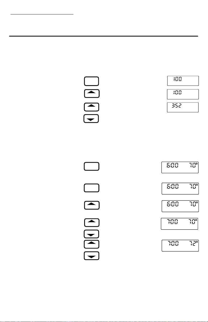
STEP 1
SET THE CURRENT DAY AND
TIME
This thermostat can be programmed either
on the wall or in hand. SEE PAGE 5 TO
SET
PRESENT
DAY/TIME
DAY
FIND OUT HOW TO REMOVE THE
THERMOSTAT FROM THE SUBBASE.
Always press the keys with fingertip or
similar blunt tool. Sharp instruments like a
AHEAD
BACK
pen or pencil point can damage the keyboard.
NOTE: Check the glossary, page 22, for
STEP 2
SET THE PROGRAM SCHEDULE
AND HEATING TEMPERATURES
WAKE
Before Beginning…
The schedule form on page 22 provides the
homeowner an opportunity to plan the
schedule.
SET
HEAT/COOL
Now…
Start by programming the WAKE time
and temperature for weekdays.
DAY
The thermostat requires a program for
WAKE. You can program LEAVE, RETURN and SLEEP or not, as desired.
AHEAD
BACK
NOTE: Some models will show 32° F instead of the
current temperature, indicating the thermostat is operating on backup batteries until the thermostat is
mounted on the wallplate and the system is powered.
definitions of unfamiliar
words.
Press and release. The display
shows 1:00 PM MON.
Press and hold until the current
day appears in the display.
Press and hold until the current
PM
TUE
M5017
time appears in the display. Be
sure AM or PM appears as desired.
Press and release. Note that
the display shows WAKE and
the preprogrammed time and
temperature.
If the display reads COOL,
press and release to switch to
HEAT.
If display reads SAT or SUN,
press and hold until MON
TUE WED THU FRI appears.
Press and hold until the display shows the desired starting time.
WAKE
WAKE
WAKE
WAKE
AM
MON TUE WED THU FRI ON HEAT
M5018
AM
MON TUE WED THU FRI ON HEAT
M5018
AM
MON TUE WED THU FRI ON HEAT
M5018
AM
MON TUE WED THU FRI ON HEAT
M5019
SET
PT
SET
PT
SET
PT
SET
PT
WARMER
COOLER
Press and hold until the display shows the desired temperature.
WAKE
AM
MON TUE WED THU FRI ON HEAT
M5020
SET
PT
If the display starts to blink while holding down TEMPERATURE WARMER or COOLER, the setting limit
has been reached. If the thermostat can switch automatically between heating and cooling, the heating temperature must be at least three degrees below the air conditioning temperature. For example, if the cooling setting
14
Page 15

T8624C,D
PROGRAMMING THE THERMOSTAT
is 75° F, the maximum heating setting is
72° F.
Program the LEAVE time and temperature, if desired.
NOTE: The LEAVE, RETURN or SLEEP
program may be canceled by holding
down the period key until the time and
Press and hold until the display shows the
desired temperature.
Program the RETURN time and temperature, if desired.
LEAVE
AHEAD
BACK
WARMER
COOLER
RETURN
AHEAD
BACK
WARMER
COOLER
SLEEP
AHEAD
BACK
WARMER
COOLER
temperature disappear from
the display.
MON TUE WED THU FRI ON HEAT
LEAVE
Press and release. The display
shows LEAVE, but no time
or temperature.
AM
MON TUE WED THU FRI ON HEAT
LEAVE
Press and hold until the display shows the desired starting time.
AM
MON TUE WED THU FRI ON HEAT
LEAVE
Press and release. The display
shows RETURN, but no time
or temperature.
Press and hold until the display shows the desired starting time.
Press and hold until the display shows the desired tem-
MON TUE WED THU FRI ON HEAT
RETURN
PM
MON TUE WED THU FRI ON HEAT
RETURN
PM
MON TUE WED THU FRI ON HEAT
RETURN
perature.
Program the SLEEP time and temperature, if desired.
Press and release. The display shows SLEEP and the
PM
MON TUE WED THU FRI ON HEAT
SLEEP
pre-programmed time and
temperature.
Press and hold until the dis-
PM
MON TUE WED THU FRI ON HEAT
SLEEP
play shows the desired starting time.
PM
MON TUE WED THU FRI ON HEAT
SLEEP
M5021
M5022
M5023
M5024
M5025
M5026
M5027
M5060
M5028
SET
PT
SET
PT
SET
PT
SET
PT
SET
PT
SET
PT
SET
PT
SET
PT
SET
PT
Press and hold until the display shows the
desired temperature.
to set the time and the WARMER/COOLER
keys to set the temperature.
DAY
Set the SATURDAY schedule. Use the same procedure
as for weekdays.
WAKE
Press and release until SAT ap-
LEAVE
pears on the display.
SLEEP
Press WAKE, LEAVE, RE-
RETURN
TURN or SLEEP to select the
AHEAD
BACK
time period.
WARMER
COOLER
Use the AHEAD/BACK keys
DAY
Set the SUNDAY schedule.
Use the same procedure as for
weekdays.
SUN ON HEAT
15 68-0134
PM
SLEEP
PM
SLEEP
SAT ON HEAT
M5029
M5030
SET
PT
SET
PT
Page 16

T8624C,D
SUN COOL
WAKE
AM
SET
PT
M5032
MON TUE WED THU FRI COOL
WAKE
AM
SET
PT
M5033
SUN ON HEAT
WAKE
AM
SET
PT
M5031
MON TUE WED THU FRI COOL
LEAVE
AM
SET
PT
M5035
PROGRAMMING THE THERMOSTAT
If cooling temperatures are not being programmed, skip Step 3 and press the RUN
PROGRAM key.
STEP 3
SET THE COOLING TEMPERATURES
The program times are the same for both
heating and cooling. Only the cooling temperatures need to be programmed if the
thermostat has already been programmed
for heating. To set times as the cooling
temperatures are programmed, use the TIME
AHEAD and BACK keys as described in
Step 2. If the times are changed for cooling,
they are also being changed for heating.
mum cooling setting is
73° F. If a lower cooling temperature is
WAKE
Press and hold until SUN ap-
LEAVE
pears on the display.
SLEEP
Press WAKE, LEAVE, RE-
RETURN
TURN or SLEEP to select
AHEAD WARMER
BACK
the time period.
COOLER
Use the AHEAD/BACK keys
to set the time and the
WARMER/COOLER keys to set the temperature.
This completes setting the program schedule and heating temperatures. To set air conditioning, go to Step 3.
WAKE
First program the WAKE temperature for weekdays.
Press and release. The display shows WAKE and the
SET
HEAT/COOL
time and temperature programmed for heating.
Press and release so COOL
shows on the display, along
DAY
with the preprogrammed cooling temperature.
If display reads SAT or SUN,
WARMER
COOLER
press and hold until MON
TUE WED THU FRI appears.
Press and hold until the dis-
MON TUE WED THU FRI COOL
WAKE
play shows the desired temperature.
If the display blinks while holding down TEMPERA-
TURE WARMER or COOLER, the setting limit has
been reached. If the thermostat can switch automatically
between heating and cooling, the cooling temperature
must be at least three degrees higher than the corresponding heating temperature. For example, if the heating setting is 70° F, the mini-
LEAVE
desired, the heating temperature first must be lowered accordingly.
Program the LEAVE temperature, if desired.
WARMER
COOLER
Press and release. The display
MON TUE WED THU FRI COOL
AM
AM
LEAVE
M5034
M5036
SET
PT
SET
PT
shows LEAVE, the time programmed for
heating, and
78° F.
RETURN
Press and hold until the display shows the desired temperature.
16
PM
MON TUE WED THU FRI COOL
RETURN
M5037
SET
PT
Page 17

T8624C,D
PROGRAMMING THE THERMOSTAT
Press and release. The display shows RETURN, the time programmed for heating,
ture, if desired.
Press and release.
pears on the display.
Press WAKE, LEAVE, RETURN or SLEEP
WARMER
COOLER
SLEEP
WARMER
COOLER
DAY
WAKE
SLEEP
WARMER
COOLER
DAY
WAKE
SLEEP
WARMER
COOLER
RUN
PROGRAM
Program the RETURN temperature, if
desired.
MON TUE WED THU FRI COOL
RETURN
and
78° F.
MON TUE WED THU FRI COOL
Press and hold until the
display shows the desired temperature.
MON TUE WED THU FRI COOL
Program the SLEEP tempera-
Press and hold until the display shows the desired temperature.
Set the cooling temperatures
for the SATURDAY schedule.
LEAVE
RETURN
Use the same procedure as for
weekdays.
Press and hold until SAT ap-
to select the time period.
Use the WARMER/COOLER
SUN COOL
LEAVE
keys to set the temperature.
Set the cooling temperatures for
RETURN
the SUNDAY schedule. Use the
same procedure as for weekdays.
Press and hold until SUN appears on the display.
Press WAKE, LEAVE, RETURN or SLEEP to select the
time period.
TUE
LEAVE
SAT COOL
M5038
M5039
M5040
M5041
M5042
M5043
SET
PT
SET
PT
SET
PT
SET
PT
SET
PT
SET
PT
PM
PM
SLEEP
PM
SLEEP
PM
SLEEP
PM
SLEEP
PM
17 68-0134
Page 18

T8624C,D
M3762
HEAT OFFCOOLAUTO
PROGRAMMING THE THERMOSTAT • OPERATING THE THERMOSTAT
Use the WARMER/COOLER keys to set the temperature.
You have completed programming the cooling temperatures.
Press and release to start the program.
Go to Step 4.
STEP 4
cleaning.
SET THE SYSTEM AND FAN
SWITCHES ON THE SUBBASE.
FAN
AUTOON
Depending on thermostat model,
some of the switch positions shown
may not be available on the thermostat. Note the positions provided
on the subbase, then set the
switch(es) as desired.
ON
FAN
AUTO
M3763
First set the fan switch.
FAN ON: The fan runs continuously. Use for improved
air circulation during special occasions or for more efficient electronic air
FAN AUTO: Normal setting
for most homes. The fan goes
on and off with the air conditioner in summer. In winter, the
COOL
AUTOHEAT OFF
fan on most
systems starts a few minutes
after the furnace comes on. It
stops a few minutes after the
HEAT OFF
AUTO
COOL
furnace goes off. The fan starts
and stops with the furnace in
some electric heat systems and
with the compressor in heat
pump systems.
HEAT OFFCOOLAUTO
Then set the system switch.
HEAT: The thermostat controls
your heating system.
AUTO (select models only): The thermostat controls
OFF: Both the heating and cooling systems are off.
This completes the programming of the thermostat.
either your heating or cooling system, depending on
room temperature.
COOL: The thermostat controls your cooling system.
Operating the Thermostat
If the thermostat is removed from the wall to program, replace it following the procedure on page 5.
TEMPORARILY CHANGING THE PROGRAM
These features allow the program to be customized for
those times when someone comes home early, or stays
up late, or plans to be out for the evening.
To keep the current temperature through the
next program period:
SKIP
NEXT
PERIOD
Press and release. The name
of the period to be skipped
will flash in the display until
the next regularly scheduled
period starts.
To go back to the temperature of the previous program period:
CHANGE
TO LAST
PERIOD
Press and release. The display will show the name of
the previous period and flash
TEMPORARY until the next
regularly scheduled period starts.
18
PM
TUE
LEAVE RETURN
PM
TUE
WAKE TEMPORARY
M5044
M5045
Page 19

T8624C,D
OPERATING THE THERMOSTAT
To temporarily raise or lower the temperature for the current period only:
PERMANENTLY CHANGING THE
PROGRAM
If the schedule changes or a different temperature is desired, any setting can be updated without affecting other program settings.
WARMER
COOLER
PRESENT
SETTING
RUN
PROGRAM
WAKE
SLEEP
DAY
AHEAD
BACK
RUN
PROGRAM
Press and hold until the desired temperature is reached.
The display will flash TEMPORARY until the next programmed time period starts.
With the system switch at the
AUTO position, press and
hold down the key to alternate between heating and cooling temperature settings for
temporary override.
Press and release to cancel
any of the temporary settings.
Press and release the desired
period key.
Press and hold until the desired
day schedule shows on the display.
Press and hold the Time or Temperature keys until the display
shows the desired new program.
Press and release to return to
normal operation.
TUE
LEAVE
LEAVE
RETURN
WARMER
COOLER
ON HEAT
TEMPORARY
M5046
PM
M5047
MANUALLY OPERATING THE
THERMOSTAT
This feature is particularly useful when on
vacation or other extended absences. It does
not cancel the program.
HOLD
TEMP
WARMER
COOLER
PRESENT
SETTING
RUN
PROGRAM
Press and release.
Press and hold to change the
temperature setting. After a
few seconds, the display will
ON HEAT
M5048
ON HEAT
M5049
show the current temperature.
Press and release to check the
temperature setting.
ON HEAT
M5050
Press and hold down to alternate between heating and
cooling temperature settings.
Press and release to cancel
hold.
PM
TUE
LEAVE
M5051
19 68-0134
SET
PT
SET
PT
SET
PT
Page 20

T8624C,D
OPERATING THE THERMOSTAT
NOTE: Moving the system switch also can-
cels hold.
CANCELING THE PROGRAM
SETTINGS
The thermostat requires time and temperature settings in the WAKE period, but any of
the others can be canceled. Weekday, Satur-
normal operation.
CHECKING THE PROGRAM TIMES
AND TEMPERATURES
normal operation.
SLEEP
LEAVE
RETURN
RUN
PROGRAM
WAKE
SLEEP
LEAVE
RETURN
DAY
RUN
PROGRAM
day and Sunday settings are
canceled separately.
Press and hold the desired pe-
MON TUE WED THU FRI ON HEAT
LEAVE
M5052
riod key until the time and temperature clear from the
display (about three seconds).
PM
MON
Press and release to return to
RETURN
M5053
Check all the stored settings without affecting the permanent program.
Press and release the desired
period key. The start time and
PM
MON TUE WED THU FRI ON HEAT
SLEEP
M5054
temperature setting will appear on the display.
Press and release to display
the next daily time and temperature for that period.
Press and release to return to
PM
SAT ON HEAT
SLEEP
MON
RETURN
M5055
PM
M5056
SET
PT
SET
PT
CHECKING THE CURRENT
TEMPERATURE SETTING
Press a single key to compare current room
temperature to the current temperature setting at any time.
PRESENT
SETTING
PRESENT
SETTING
Press and release. The display will show the current
temperature setting for several seconds, then revert to the room temperature.
To check the heating and cooling settings with the system switch at the AUTO position, press and hold down
to alternate between the heating and cooling settings.
During recovery from energy savings, the setting displayed will not match the programmed setting. This is
because the thermostat gradually changes the temperature setting during recovery to provide most efficient use
of the heating or cooling equipment.
20
ON HEAT
M5057
SET
PT
Page 21

SYMPTOM POSSIBLE CAUSE ACTION
ROOM TEMPERATURE DISPLAY
˚
F.
IS 32
FURNACE OR AIR CONDITIONER
WON'T OPERATE.
PARTIAL DISPLAY INOPERATIVE THERMOSTAT REPLACE THERMOSTAT.
PRESENT SETTING APPEARS
INACCURATE.
CANNOT TEMPORARILY OVERRIDE
BOTH HEATING AND COOLING
SETTINGS IN AUTO MODE.
THERMOSTAT TEMPERATURE NEEDS
TO BE ADJUSTED ON A REGULAR
BASIS.
PROGRAM IS LOST DUE TO POWER
OUTAGE OR DISPLAY GOES BLANK
WHEN POWER IS TURNED OFF.
DISPLAY FLASHES WHILE
PROGRAMMING.
DISPLAY FLASHES DURING
OPERATION.
NO ac POWER TO THERMOSTAT
NO ac POWER TO THERMOSTAT
THERMOSTAT INOPERATIVE CONDUCT SELF-TEST; SEE CHECKOUT.
PRESENT SETTING TOO LOW/HIGH
SYSTEM SWITCH ON THERMOSTAT
IN WRONG POSITION.
MINIMUM-OFF TIMES IN THERMOSTAT
IN OPERATION ON COOLING
INCORRECT WIRING CHECK CIRCUIT DIAGRAM.
FURNACE OR AIR CONDITIONER
INOPERATIVE
THERMOSTAT MOUNTED
INCORRECTLY ON BASE.
THERMOSTAT IS IN RECOVERY
MODE.
NOT USING PRESENT SETTING KEY.
WARMER/COOLER KEYS BEING
USED TO ADJUST TEMPERATURE
BATTERIES ARE INCORRECTLY
INSTALLED.
BATTERIES ARE DEAD.
IMPROPER PROGRAM SEQUENCE
AUTOMATIC THERMOSTAT HEATING
OR COOLING TEMPERATURE CAN
NOT BE SET CLOSER THAN 3 F.
PROGRAMMING HAS BEEN LOST
BECAUSE OF A POWER OUTAGE.
O
CHECK POWER TO FURNACE OR AIR CONDITIONER.
–ON-OFF SWITCH
–FUSE OR CIRCUIT BREAKER
–LOOSE 24V CONNECTION
–AT THERMOSTAT
–AT FURNACE /AIR CONDITIONER
–INCORRECT WIRING
–CHECK WIRING DIAGRAM
CHECK POWER TO FURNACE OR AIR CONDITIONER.
–ON-OFF SWITCH
–FUSE OR CIRCUIT BREAKER
–LOOSE 24V CONNECTION
–AT THERMOSTAT
–AT FURNACE /AIR CONDITIONER
–INCORRECT WIRING
–CHECK WIRING DIAGRAM
ADJUST TEMPERATURE BY PUSHING WARMER/
COOLER KEYS.
RESET THERMOSTAT SYSTEM SWITCH.
WAIT 5 -10 MIN. OR USE SELF-TEST IN THERMOSTAT.
SEE CHECKOUT.
CONSULT FURNACE OR AIR CONDITIONER
INSTRUCTIONS.
CHECK THAT HEAT OR COOL SYSTEM POWER IS ON.NO POWER TO THERMOSTATNO DISPLAY
SEE INSTALLATION INSTRUCTIONS FOR CORRECT
MOUNTING.
• NORMAL OPERATION THERMOSTAT TURNS ON
HEATING/COOLING EARLY TO MEET TEMPERATURE
SETTING AT PROGRAMMED TIMES.
• RECOVERY CAN BE ENDED BY PUSHING WARMER/
COOLER KEYS.
PRESS AND HOLD DOWN PRESENT SETTING KEY TO
ALTERNATE BETWEEN HEATING AND COOLING SETTINGS.
REPROGRAM THERMOSTAT TO MAKE PERMANENT
CHANGE IN PROGRAM. WARMER/COOLER KEYS ARE
TEMPORARY UNLESS PERIOD KEY IS PRESSED FIRST.
REMOVE AND REPLACE PER MARKINGS ON THERMOSTAT.
REPLACE BATTERIES.
CHECK PROGRAMMING INSTRUCTIONS FOR CORRECT
PROGRAM SEQUENCE.
SET HEATING AND COOLING TEMPERATURES 3 F OR
MORE APART.
REPROGRAM ACCORDING PROGRAMMING INSTRUCTIONS
(MAKE SURE BATTERIES ARE INSTALLED).
T8624C,D
TROUBLESHOOTING
O
M5234A
21 68-0134
Page 22

T8624C,D
GLOSSARY
Recovery
The time when the thermostat operates the heating or
air conditioning equipment to return the home from the
energy saving temperature to the comfort temperature.
Troubleshooting
Glossary
Comfort temperature
The temperature desired when active and occupying
the home.
Energy-saving temperature
The lower (heating) or higher (cooling) temperature
that allows savings on heating and cooling costs when
asleep or away. Also called the setback (heating) or
Period Time
WAKE 6:00 AM 70° F78° F
LEAVE ——— No program ————
RETURN ——— No program ————
SLEEP 10:00 PM 60° F78° F
setup (cooling) temperature.
Period key
One of the four keys—WAKE, LEAVE, RETURN or
SLEEP—to check or program the start time and
temperatue for a time period.
Preprogrammed schedule
This is the schedule programmed into the thermostat
at the factory. It sets a night program that provides
energy savings when homeowner sets no program, or if
personal program is lost for any reason. The program,
which is the same for all days of the week, is:
Program
The times and temperatures homeowner sets to define
the comfort and energy saving periods for each day
schedule.
home.
RETURN—The time period that the house is at a comfortable temperature for family activities in the evening before
bedtime.
SLEEP—The time period that the temperature can be set back (winter) or set up (summer) for energy savings
because the family is sleeping. It can be set to start at the family’s normal bedtime. Often the SLEEP program is set
only for the heating season so family members can sleep cool in the cooling season.
Weekday program schedule
The schedule of WAKE, LEAVE, RETURN and SLEEP period start times and temperatures programmed to run
Monday through Friday.
Start
Temperature
Heating Cooling
The thermostat starts the recovery period early so the
home will be at the comfort setting by the time the
homeowner has chosen.
Saturday program schedule
The schedule of WAKE, LEAVE, RETURN and
SLEEP period start times and temperatures programmed
to run on Saturdays.
Setback
Reducing the temperature in the home for a set period
in heating for energy savings. The lower temperature is
the energy saving temperature.
Setup
Raising the temperature in the home for a set period
in cooling for energy savings. The higher temperature is
the energy saving temperature.
Setpoint
The thermostat temperature setting the homeowner
selects. The thermostat turns the heating or cooling
equipment on and off to maintain this temperature at the
thermostat location until another temperature setting
(setpoint) goes into effect.
Sunday program schedule
The schedule of WAKE, LEAVE, RETURN and
SLEEP period start times and temperatures programmed
to run on Sundays.
SYSTEM light
This light glows whenever the thermostat is calling
for heating or air conditioning.
Time period
One of four program periods: WAKE, LEAVE, RETURN and SLEEP available with the thermostat. One
period begins when the previous program period ends:
WAKE—The time period that the house is at a com-
fortable temperature while the family gets up and gets
ready to leave for work or school. This is the only
period that must contain a time and temperature.
LEAVE—The time period that the temperature can
be set back (winter) or set up (summer) for energy
savings because the family is usually away from
22
Page 23

23 68-0134
Page 24

Home and Building Control Home and Building Control
Honeywell Inc. Honeywell Limited—Honeywell Limitée
1985 Douglas Drive North 740 Ellesmere Road
Golden Valley, MN 55422 Scarborough, Ontario
M1P 2V9
Printed in U.S.A.
 Loading...