

Page 1

(7-Day Programming)
Chr onotherm III™
Heat Pump Thermostats
The T8611M Chronotherm III Programmable
Thermostat provides automatic control of multistage heat pump systems and offers users the
highest standard of comfort and convenience
available with energy savings.
T8611M
■ Full seven-day program capability; different sched-
ules may be selected for every day.
■ Can be programmed in hand (with batteries in-
stalled) or on the wall to provide up to four tem-
perature periods per day.
■ Large digital clock (liquid crystal display) indi-
cates continuous time-of-day, day-of-week, cur-
rent period and room temperature.
■ Adaptive Intelligent Recovery™ brings room tem-
perature to programmed temperature at program-
med time, maximizing comfort and energy sav-
ings.
■ Temperature control program maintains tempera-
ture within 1° F of setpoint.
■ Temporary program override available by using—
—WARMER and COOLER keys.
—SKIP next period key.
—CHANGE to last period key.
■ HOLD TEMP key provided for indefinite program
override (vacation/holiday).
■ Installer self-test with time delay override saves
installation time.
■ SYSTEM light-emitting diode (LED) on thermo-
stat indicates system is energized.
■ AUX. HT., EM. HT., CHECK LEDs available on
select models.
■ Automatic heat/cool changeover.
■ Batteries included provide power to maintain clock
and memory during power failures.
■ Switching subbase with wiring terminals included.
■ Powered directly from control transformer.
■ Model available with separate sensor for remote
CONTENTS
Specifications ................................................. 2
Ordering Information..................................... 2
Selection/Application ..................................... 5
Installation ................................................... 12
Checkout....................................................... 18
Programming The Thermostat ..................... 20
Operating The Thermostat ........................... 25
Operation ..................................................... 27
Troubleshooting ........................................... 29
Glossary ....................................................... 30
Table of Contents ......................................... 32
temperature sensing.
1 68-0076—1
C. H. • Rev. 10-92 • ©Honeywell Inc. 1992 • Form Number 68-0076—1
Page 2

T8611M
SPECIFICATIONS • ORDERING INFORMATION
TRADELINE MODELS
TRADELINE models are selected and packaged to
provide ease of stocking and handling and also maximum
TABLE 1—TRADELINE MODELS AVAILABLE.
Stages Changeover Switching
Thermostat Heat Cool Type System Fan Application Program
T8611M* 3 2 Automatic EM. HT.-HEAT-OFF- ON-AUTO Heat Pump 7-Day
AUTO-COOL
*Model available with separate sensor for remote temperature sensing.
Specif ications
replacement value.
TRADELINE models available are listed in Table 1.
LIGHT-EMITTING DIODES (LEDs):
SYSTEM LED (yellow) on thermostat lights during
thermostat heating and cooling ON cycles.
EM.HT. LED (red) on subbase lights when system
switch is in EM.HT. On some systems, light may
indicate need to switch to EM.HT. because of heat
pump problem.
AUX. HT. LED (green) on subbase lights when ther-
mostat is calling for operation of auxiliary heat.
CHECK LED (yellow) on subbase lights when an
equipment or system problem needs to be checked.
Consult heat pump literature to determine meaning.
VOLTAGE RATING: 15 to 30 Vac.
CURRENT RATING: 1.6A maximum, total per stage.
OPERATING HUMIDITY RANGE: 5 to 90 percent rela-
tive humidity, noncondensing.
OPERATING AMBIENT TEMPERATURE RANGE:
40° F to 110° F [4° C to 43° C].
SET POINT RANGE: 45° F to 88° F [7° C to 31° C].
CALIBRATION: Self-calibrating thermostat and thermo-
meter to ±1° F.
SHIPPING TEMPERATURE: -20° F to +120° F [-29° C
to +49° C].
CYCLES PER HOUR ADJUSTMENT:
Auxiliary heating—factory-set at 3 cph (adjustable to
6 cph for special systems); minimum off-time of five
minutes.
Nonauxiliary heating and cooling—factory-set (not
field adjustable); minimum off-time of five minutes.
FINISH: Beige matte with decorative brushed metal face-
plate.
DIMENSIONS: Thermostat (mounted on subbase)—7 in.
[178 mm] long, 5-5/16 in. [135 mm] high, 1-3/4 in.
[44 mm] deep. See Fig. 1 for subbase dimensions. See
Fig. 2 for remote sensor dimensions.
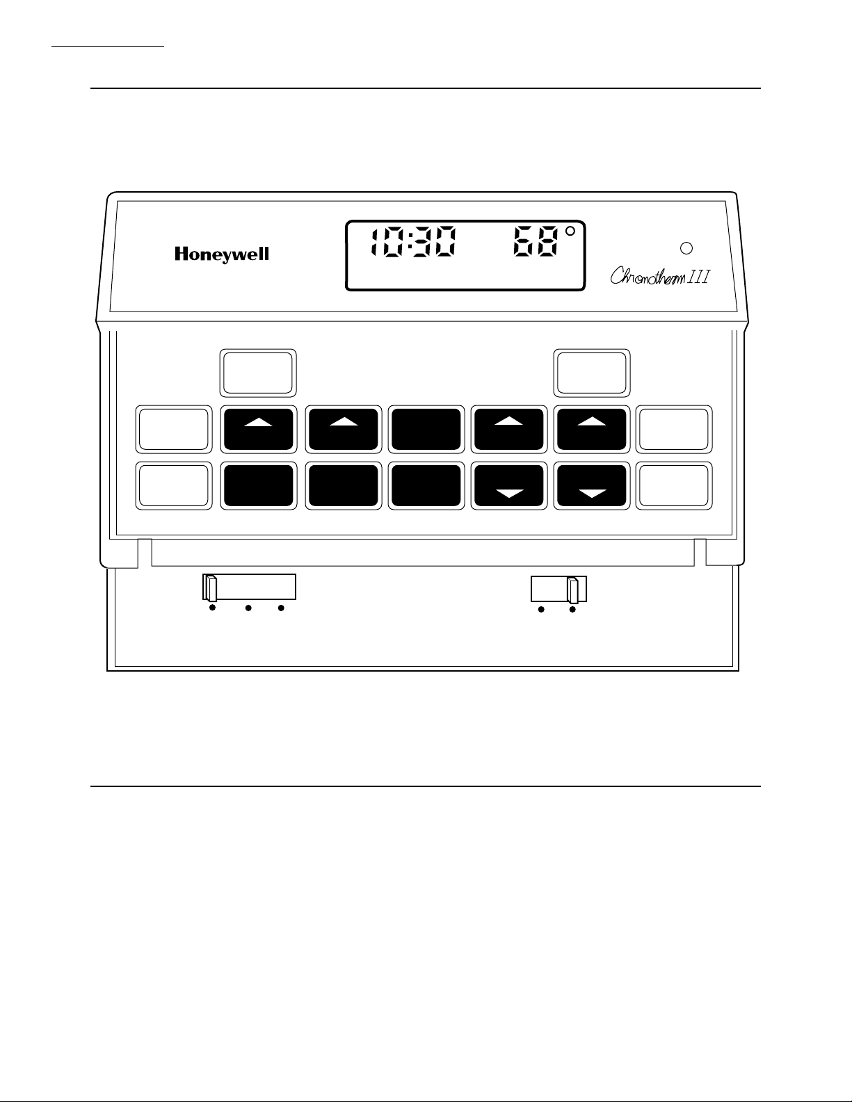
TYPICAL KEYPAD: See Fig. 3.
REPLACEMENT PARTS:
202905AA Remote Temperature Sensor.
220529 Replacement Door.
AAA alkaline batteries, available locally.
ACCESSORIES:
193121A Cover Plate Assembly. Includes cover plate,
adapter ring and screws; 6-9/10 in. x 4-3/4 in. [175
mm x 121 mm]. Covers marks left by old thermostat.
Allows mounting on vertical or horizontal outlet
box.
TG512 Universal Thermostat Guards. Includes clear or
opaque plastic or metal cover, ring base, opaque
plastic wallplate, tumbler lock with two keys.
TG586A Locking Cover.
Ordering Inf ormation
When purchasing replacement and modernization products from your TRADELINE® wholesaler or distributor, refer to the
TRADELINE Catalog or price sheets for complete ordering number, or specify—
1. Model number. 3. Remote temperature sensing, if desired.
2. Number of heat and cool stages desired.
If you have additional questions, need further information or would like to comment on our products or services, please write or phone:
1. Your local Honeywell Home and Building Control Sales Office (check white pages of your phone directory).
2. Home and Building Control Customer Satisfaction
Honeywell inc., 1885 Douglas Drive North
Minneapolis, Minnesota 55422-4386 (612) 951-1000
In Canada—Honeywell Limited/Honeywell Limitée 740 Ellesmere Road, Scarborough, Ontario M1P 2V9. International sales
and service offices in all principal cities of the world. Manufacturing in Australia, Canada, Finland, France, Germany, Japan,
Mexico, Netherlands, Spain, Taiwan, United Kingdom, U.S.A.
2
Page 3
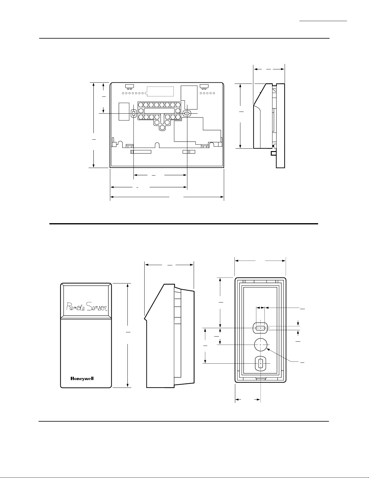
Fig. 1—T8611 Subbase mounting dimensions in in. [mm].
13
1
16
[46]
5
5
16
[135]
5
3 [83]
16
3
4 [121]
4
M5181A
7 [179]
4
[104]
T8611M
SPECIFICATIONS
31
1
32
[50]
3
32
Fig. 2—202905AA Remote Sensor dimensions in in. [mm].
FRONT
4
[104]
3
32
SIDE
1
[50]
31
32
BACK
2
[51]
31
[50]
1
32
41
[16]
64
3
1
[35]
8
[25]
1
19
[8]
64
9
[4]
64
1
DIA.
2
[13]
M5244
3 68-0076—1
Page 4
T8611M
SPECIFICATIONS
Fig. 3—Typical thermostat keypad.
SET
PRESENT
DAY/TIME
HOLD
TEMP
PROGRAM
HEAT/COOL
HEAT OFF
RUN
DAY
SET
COOL
PERIOD
CANCEL
PERIOD
MIDDAY
COPY
FROM
COPY
WED
TO
AM
TIME
AHEAD
BACK COOLER
ROOM
HEAT ON
TEMPERATURE
PRESENT
SETTING
WARMER
FAN
ON AUTO
SYSTEM
SKIP
NEXT
PERIOD
CHANGE
TO LAST
PERIOD
M5360
4
Page 5

T8611M
SELECTION/APPLICATION
Selection/A pplication
The T8611 Thermostat uses the latest microelectronic
design and control technology to provide home and building owners with the highest level of comfort available and
optimal energy savings in a package that is easy to use and
easy to live with.
The following section is a guide to selection and application of the best thermostat to meet individual customer
needs.
PROGRAMMING
Does the thermostat selected accommodate the
customer’s daily schedule, lifestyle or work schedule?
Refer to choices below.
TRADELINE Daily Temperature
Device Programming Selection
T8611G,R* Weekday, 4 heat and
Sat, Sun. 4 cool
T8611M 7-day 4 heat and
(each day 4 cool
different)
IF RETROFIT/REPLACEMENT APPLICATION,
CONSIDER
• equipment requirements
— system switching (manual: EM. HT.-HEAT-OFF-
COOL, automatic: EM. HT.-HEAT-OFF-AUTOCOOL).
— unique heat pump functions of emergency or
supplemental heat, changeover on heat or cool,
and status indication.
— Table 3 lists typical applications by manufac-
turer.
• existing wiring
— Are there enough conductors to operate the equip-
ment and the thermostat? Can a new cable be
pulled?
• existing thermostat
— Table 3 is a guide for replacing popular Honeywell
standard nonprogrammable thermostats with a
T8611.
SECURITY
Does the thermostat selected provide access to programming and the override features that will best suit the
application? Refer to choices below.
*Specifications form 68-0057 for information.
IF NEW CONSTRUCTION APPLICATION,
CONSIDER
• equipment type (see manufacturer’s specifications)
— system switching required
— status indication provided
• control wiring—number of conductors required to
operate equipment and thermostat.
IMPORTANT: The T8611 requires a conductor to trans-
former common to provide continuous 24V power
for thermostat operation. This feature is commonly
specified and provided by equipment manufacturer.
Typical
Access Application Device
Free access to Home or T8611
programming owner-occupied
and adjustment/ commercial
override. building.
Restricted Public building. T8611 with TG512
access to Locking Cover;
device. T8611 with remote
temperature
sensing.
5 68-0076—1
Page 6
T8611M
SELECTION/APPLICATION
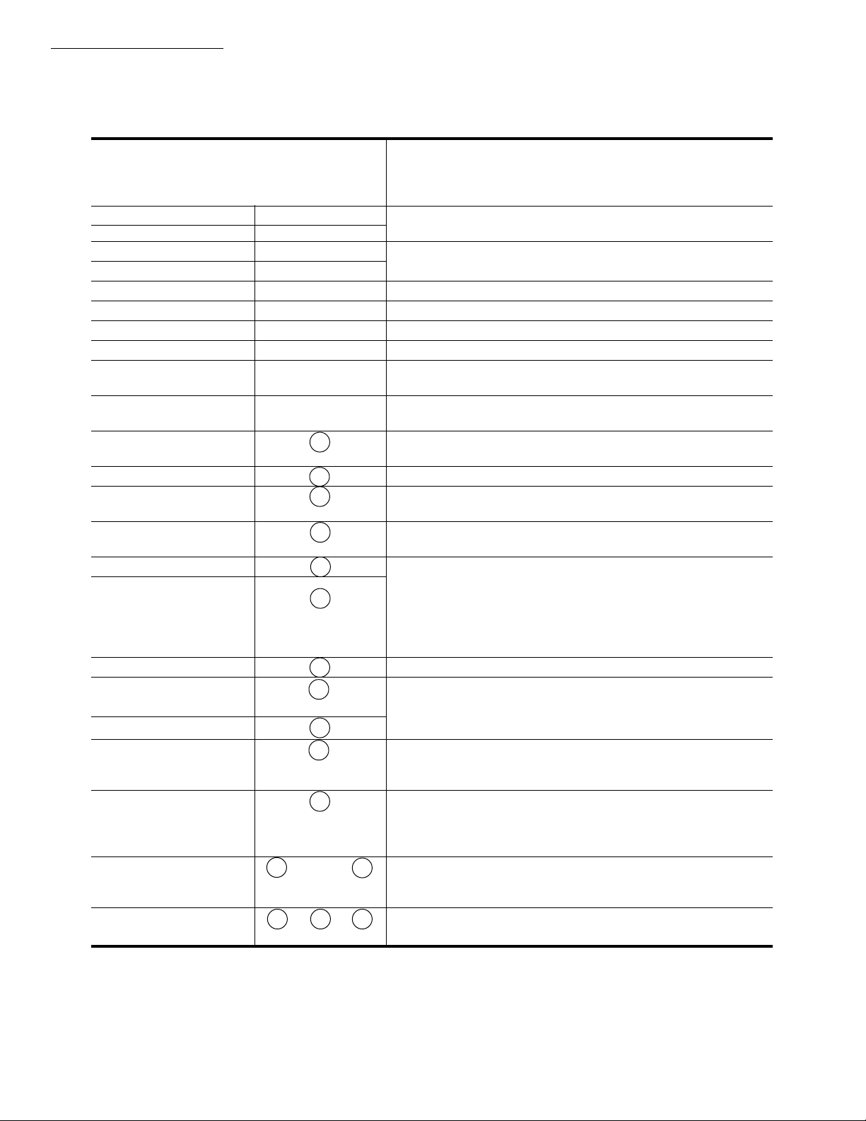
Table 2 lists features and wiring terminal functions of the TRADELINE T8611M thermostat.
TABLE 2—T8611M FEATURES AND TERMINALS.
T8611M
FEATURES
COMMENTS
Heating Stages 3 May be applied to 2-stage heat pump systems; see wiring
Cooling Stages 2 diagrams Figs. 6 and 7.
Changeover Auto
Programming 7-day
SYSTEM LED Yes Lights on call for heat or cool.
EM. HEAT LED (red) Yes Lights continuously in EM. HEAT mode.
AUX. HEAT LED (green) Yes Lights during call for final auxiliary heat stage.
CHECK LED (yellow) Yes Field wired option; indicates equipment malfunction.
Remote Temperature Yes Available on T8611M7040 only. (202905A Remote Sensor
Sensing included).
WIRING TERMINAL
FUNCTION
24 Vac Common C Must be connected to control transformer to operate
thermostat.
24 Vac Power R
Compressor, Stage 1 Y
heat and cool.
Compressor,
Stage 2 cool unconnected.
Second Stage Heat
Auxiliary (Resistive) second stage is compressorized, connect stage 2 to W2;
Third Stage Heat
Fan G
Changeover Heat Mode B O/B changeover terminals are energized continuously
Changeover Cool Mode O
System Monitor, L Energizes EM. HEAT LED when externally powered.
continuously energized
in EM. HEAT mode.
Emergency Heat E
energized on call for
stage 1 heat in
EM. HEAT mode
Check LED terminals
to indicate equipment
malfunction
Remote Temperature
Sensing 202905A Remote Sensor for proper thermostat operation.
Y2
W2
W3
X1 X2
S1 S2 S3
If applying T8611M to 1-stage cooling system, leave Y2
If applying T8611M to 2-stage heat systems in which the
leave W3 unconnected.
If 2-stage heat system in which the second stage is auxillary
(electric resistive), connect auxiliary stage to W3; leave
W2 unconnected.
following first call for cool or heat, respectively.
See wiring diagrams for hookup alternatives.
Available on T8611M7040 only. Must be connected to
6
Page 7
SELECTION/APPLICATION
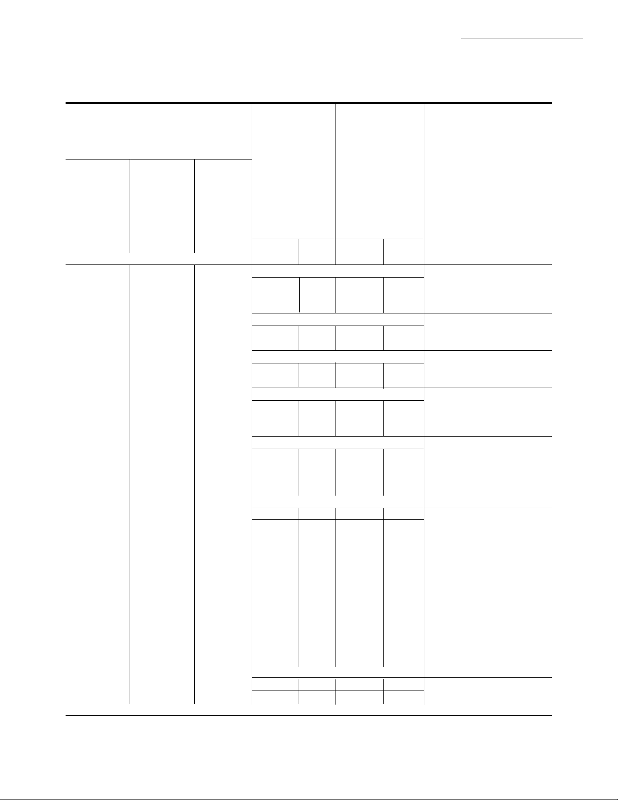
TABLE 3—T8611 GUIDE FOR REPLACING POPULAR T874 AND T872 THERMOSTATS,
BY EQUIPMENT MANUFACTURER.
(NOTE: Also see form 70-6627, Heat Pump Thermostat Cross Reference Guide, for wiring hookup illustrations.)
Thermostat (Subbase Included)
Auto Manual
Changeover Changeover
Weekday, Weekday,
Sat, Sun Sat, Sun Auto
T8611G1004 T8611R1000 Changeover
T8611G1012 (°C)T8611R1042 (°C) 7-day
T8611G1103 T8611R1141 T8611M7008
(Premier White) (Premier White) T8611M7040cThermostat Subbase Thermostat Subbase
(also see form 68-0057, Specifications) T874 Q674 T872 Q672 Comments
Amana
• D1009 F1022 D1003 F1026 Separate first stage
• D1017 D1011 heat/cool terminals W1, Y1.
• D1165 D1300
Arco/Comfort Maker
••
a
• na na na na Check LED optional;
X = X1, jump X2 to C.
Arco/Friedrich
••
a
• na na na na Changeover on heat,
check LED optional.
Bard
••
a
• N1024 F1261 N1036 F1299 Changeover on heat (typical),
• • • R1129 L1181 R1146 L1185 check LED optional, equipment
terminal W1 to thermostat B.
Bryant, Day-Night, Payne
b
•
••
••
changeover
••
a,b
•
a
a
a
b
•
G1451 F1113bG1166 F1125 Check LED optional; F = X1,
• G1261 F1253 jump X2 to C. Note: P terminal
• J1010 L1371 G1174 available on manual
• R1335 L1405 (T8611R) models only.
Carrier
••
a
• G1055 J1035 G1075 J1054 Check LED optional (typical)
• • • G1071 L1041 G1158 L1052
• • • G1121 L1397 G1182
• • • P1005 G1273
• • • G1307
• • • G1257 L1169
• • • J1002 L1371
• • • J1028 L1074
• D1074 F1059 Multistage heat pump
• F1030
• F1063
• E1114 No Supl. Ht. function
• E1042 No Supl. Ht. function
• D1264 L1116 Multistage heat pump
Command Aire
• • • H1005 C1041 H1009 C1086 No AUX. HEAT or EM.
• • • G1352 C1066 HEAT required; Y1 = 0
a
No CHECK LED.
b
Dual transformer requires conversion to single transformer.
c
Model includes separate sensor for remote temperature sensing.
(continued)
T8611M
7 68-0076—1
Page 8

T8611M
SELECTION/APPLICATION
TABLE 3—T8611 GUIDE FOR REPLACING POPULAR T874 AND T872 THERMOSTATS,
BY EQUIPMENT MANUFACTURER (Continued).
(NOTE: Also see form 70-6627, Heat Pump Thermostat Cross Reference Guide, for wiring hookup illustrations.)
Thermostat (Subbase Included)
Auto Manual
Changeover Changeover
Weekday, Weekday,
Sat, Sun Sat, Sun Auto
T8611G1004 T8611R1000 Changeover
T8611G1012 (°C)T8611R1042 (°C) 7-day
T8611G1103 T8611R1141 T8611M7008
(Premier White) (Premier White) T8611M7040cThermostat Subbase Thermostat Subbase
(also see form 68-0057, Specifications) T874 Q674 T872 Q672 Comments
Coleman
••
a
• R1368 L1421 na na Late models optional check
LED. Z = X2, jump X1 and C,
K = L.
• • • na na na na Earlier T.H.E. models with
reverse-acting EM. HT.
require relay isolation.
Crispaire/Marvair
• • • G1089 F1162 G1208 F1166
F1204 F1323
• • • R1111 L1215 R1156 L1094
Fedders/Airtemp/Climatrol
a
•
a
•
a
•
C1398 L1090 C1509 L1102 Separate first stage heat/cool
C1406 C1517 terminals required; check LED
C1414 C1541 optional; equipment terminal
K to thermostat E.
Florida Heat Pump
••
a
• na na na na Optional check LED;
X = X1, jump X2 to C.
Heatwave/Southwest Mfg.
• • • G1105 F1170 G1232 F1224
Heil Quaker/Whirlpool/Tempstar
• • • R1137 L1132 R1172 L1193 Equipment terminal B
to thermostat C.
Honeywell
• A-D (typ.) F1006 A-D (typ.) F1000 Separate first stage
• F1022 F1026 heat/cool terminals.
• F1048 F1042
• C1000 F1089 C1004 F1075
• • C1018 C1038
• • C1117 C1350 °C
• • C1240 C1566 °C
• • • G1246 F1212 G1224 F1208 TRADELINE
• • • G1444 G1000 F1018
• • • G1018 °C
• • • G1212 F1238 G1083 F1158
• • • G1139
a
No CHECK LED.
b
Dual transformer requires conversion to single transformer.
c
Model includes separate sensor for remote temperature sensing.
(continued)
8
Page 9
T8611M
SELECTION/APPLICATION
TABLE 3—T8611 GUIDE FOR REPLACING POPULAR T874 AND T872 THERMOSTATS,
BY EQUIPMENT MANUFACTURER (Continued).
(NOTE: Also see form 70-6627, Heat Pump Thermostat Cross Reference Guide, for wiring hookup illustrations.)
Thermostat (Subbase Included)
Auto Manual
Changeover Changeover
Weekday, Weekday,
Sat, Sun Sat, Sun Auto
T8611G1004 T8611R1000 Changeover
T8611G1012 (° C)T8611R1042 (° C) 7-day
T8611G1103 T8611R1141 T8611M7008
(Premier White) (Premier White) T8611M7040cThermostat Subbase Thermostat Subbase
(also see form 68-0057, Specifications) T874 Q674 T872 Q672 Comments
Honeywell (continued)
• • • N1016 F1220 N1002 F1133 Changeover on heat; equip-
• • • N1040 F1261 N1028 F1216 ment terminal C to thermostat
• • • R1004 B1042 R1008 B1046 Y, W1 to B, K to E.
• • • B1109 R1057 L1037
• • • R1152 L1207 R1198 L1227
• • • R1285 L1157
• • • R1350 L1181
Janitrol/Tappan
• • • G1147 F1139 G1109 F1117 Equipment terminal C to
thermostat C.
Lennox NOTE: Rewire for single 75
VA
transformer if two-transformer
system.
• • • G1014 F1113 G1026 F1067
• • • G1022 E1148 G1125 E1019 °C
• • • G1162 G1091 DoD specs—use guard.
• • • G1154 F1105 G1323 L1201
• • • R1024 B1160
• • • R1040 B1202
• • • R1178 L1355
• • • L1165
• • • C1148 L1165
• D1207 L1199 Two-speed unit; optional check
• L1389 LED; thermistor A not used.
Ter- minal Conversion
Guide:
Lennox Standard
Transformer
Common X C
Transformer
Power VR (in) R
V (out)
Compressor M Y
M2 Y2
Aux. Heating Y W2
Fan F G
Changeover R O
System Monitor L L,X1,X2
Em.Heat (cycling) E E
Thermistor A T (not
required)
a
No CHECK LED.
b
Dual transformer requires conversion to single transformer.
c
Model includes separate sensor for remote temperature sensing.
9 68-0076—1
(continued)
Page 10

T8611M
SELECTION/APPLICATION
TABLE 3—T8611 GUIDE FOR REPLACING POPULAR T874 AND T872 THERMOSTATS,
BY EQUIPMENT MANUFACTURER (Continued).
(NOTE: Also see form 70-6627, Heat Pump Thermostat Cross Reference Guide, for wiring hookup illustrations.)
Thermostat (Subbase Included)
Auto Manual
Changeover Changeover
Weekday, Weekday,
Sat, Sun Sat, Sun Auto
T8611G1004 T8611R1000 Changeover
T8611G1012 (° C)T8611R1042 (° C) 7-day
T8611G1103 T8611R1141 T8611M7008
(Premier White) (Premier White) T8611M7040cThermostat Subbase Thermostat Subbase
(also see form 68-0057, Specifications) T874 Q674 T872 Q672 Comments
Luxaire
• • • G (Borg F1188 G1315 F1281
Warner)
Magic Chef
• na na na na Earlier PB series, separate first
••
a
• na na na na Late PE series, optional check
stage heat/cool.
LED; X1 = X1, jump X2 to R.
Rheem/Ruud
• • • G1097 F1238 G1133 F1158
• • • G1238 G1141 L1157
• • • R1081 L1045
• • • G1220 R1107 L1136
• • • R1079
• • • R1095
Square D/Sun Dial
a
•
C1224 F1071 C1525 F1182 Separate first stage heat/cool
required; optional check LED;
X = X1, jump X2 to R.
Trane/General Electric
••
a
• G1204 J1043 G1059 J1039 Optional check LED; F = X1,
jump X2 to C; T not used;
equipment terminal B to thermostat C, R to R, Y to Y (Y1 +
W1), W to W2, G to G, 0 to 0,
X2 to E.
Weather King
• • • na na G1265 F1265 Optional check LED; X = X1,
jump X2 to R; equipment terminal C to thermostat C, W1
to Y (W1 + Y1), E to W2,
Y1 to 0.
a
No CHECK LED.
b
Dual transformer requires conversion to single transformer.
c
Model includes separate sensor for remote temperature sensing.
(continued)
10
Page 11

SELECTION/APPLICATION
TABLE 3—T8611 GUIDE FOR REPLACING POPULAR T874 AND T872 THERMOSTATS,
BY EQUIPMENT MANUFACTURER (Continued).
(NOTE: Also see form 70-6627, Heat Pump Thermostat Cross Reference Guide, for wiring hookup illustrations.)
Thermostat (Subbase Included)
Auto Manual
Changeover Changeover
Weekday, Weekday,
Sat, Sun Sat, Sun Auto
T8611G1004 T8611R1000 Changeover
T8611G1012 (° C)T8611R1042 (° C) 7-day
T8611G1103 T8611R1141 T8611M7008
(Premier White) (Premier White) T8611M7040cThermostat Subbase Thermostat Subbase
(also see form 68-0057, Specifications) T874 Q674 T872 Q672 Comments
Wesco/Addison
• • • G1287 F1253 Equipment terminal C1 to thermostat C, W1 to Y (W1 + Y1),
• • • R1012 B1109 R1016 B1103 Y1 to 0. Common to thermostat
• • • G1265 F1265 direct from control transformer.
• • • G1281
Westinghouse
• • • G1048 F1121 G1034 F1141
• • • F1246 F1091
• • • F1279 F1257
• • • J1019 J1013
• • • J1050 J1062
• • • R1103 L1108 R1149 L1110
• • • L1173 L1128
• • • L1151
• na na na na Separate first stage heat/cool
ter- minals required.
• D1108 L1223 G1356 L1219 2-speed heat pump; optional
check LED; L = X1, jump
X2 to C.
White Rodgers
• • • na na na na 1F58-910/S28 series.
Williamson
• • • R1236 L1348 na na
• • • N1008 F1196 na na Changeover on heat; W1 = B.
York/Borg Warner
••
a
• G1170 J1027 G1042 J1021 Optional check LED; X = X1,
• • • G1295 F1311 G1299 L1177 jump X2 to C; equipment ter-
• • • G1345 L1363 G1331 D1077 minal B to thermostat C,
• • • G1402 D1032 G1364 W to W2, H to B, T not re-
quired.
• • • G1410 G1398
• • • G1428
• • • G1436
• • • R1046 L1017 R1032 L1011
• • • R1169 L1330
• • • R1251 L1272
Zone Aire
• • • N1040 F1261 Changeover on heat;
• • • R1350 L1181 W1 = B.
a
No CHECK LED.
b
Dual transformer requires conversion to single transformer.
c
Model includes separate sensor for remote temperature sensing.
11 68-0076—1
T8611M
Page 12

T8611M
INSTALLATION
Installation
COMPATIBILITY
The T8611 Thermostats will replace most heat pump
system thermostats. As long as ac power is continuously
available to the thermostat, the thermostat will be compatible with almost any low-volt control system.
WHEN INSTALLING THIS PRODUCT…
1. Read these instructions carefully. Failure to follow
them could damage the product or cause a hazardous
condition.
2. Check the ratings given on the product to make sure
the product is suitable for your application.
3. Installer must be a trained, experienced service technician.
4. Allow thermostat to warm to room temperature
before operating.
5. After installation is complete, check out product
operation as provided in these instructions.
CAUTION
!
Disconnect power supply to prevent electrical
shock or equipment damage.
LOCATION
Thermostat with Integral Sensor
Install thermostat and subbase about 5 ft. [1.5 m] above
the floor in an area with good air circulation at room
temperature.
Do not install the thermostat where it may be affected
by—
— drafts or dead spots behind doors, in corners or under
cabinets.
— hot or cold air from ducts.
— radiant heat from sun or appliances.
— concealed pipes and chimneys.
— unheated (uncooled) areas behind the thermostat,
such as an outside wall.
This thermostat requires a single transformer. A twotransformer system may require turning off two switches
or disconnects, and rewiring to run the thermostat from a
single transformer. Make sure the transformer has adequate power (VA) for the heating/cooling control system.
Add current ratings of the system components (such as
auxiliary heat relay, changeover relay, fan relay). Multiply
this total by 24V to determine transformer VA required.
Remove any existing wallplate or subbase from wall.
Label or write down each wire color with the letter or
number on the wiring terminal as the wire is removed to
avoid miswiring later.
IF NEW INSTALLATION
Run cable to a hole at the selected wall location for
thermostat and remote sensor, and pull about 3 in. [76 mm]
of wire through the opening. Color-coded, 18-gauge thermostat cable with at least one conductor for each wiring
terminal is recommended. Good service practice recommends selecting cable with one or two more conductors
than the immediate application requires.
If using thermostat model with remote temperature
sensing, run 3-wire, 18-gauge thermostat cable from the
thermostat location to the sensor location (200 ft. [61 m]
maximum). Route cable away from sources of electrical
noise.
MOUNTING SUBBASE
IMPORTANT: Set the subbase system switch in the OFF
position before mounting.
The subbase does not require leveling for operation, but
for appearance only.
Remove thermostat from subbase (Fig. 4).
Thermostat with Remote-Mounted Sensor
Install thermostat in an area that is accessible for setting
and adjusting the temperature and settings.
Install remote temperature sensor in an area with good
air circulation at average temperature.
Do not install the sensor where it may be affected by—
— drafts or dead spots behind doors, in corners, or
under cabinets.
— hot or cold air from ducts.
— radiant heat from sun or appliances.
— concealed pipes and chimneys.
— unheated (uncooled) areas behind the sensor, such
as an outside wall.
IF REPLACING AN EXISTING THERMOSTAT
Turn thermostat power off at furnace or heat pump.
12
Page 13

Fig. 4—Removing thermostat from subbase.
REMOTE SENSOR
COVER
REMOTE
SENSOR BASE
WALL
MOUNTING HOLES
WIRING
HOLE
M1549B
WALL
ANCHORS (2)
MOUNTING
SCREWS (2)
WIRES
THROUGH
WALL
OPENING
The subbase mounts directly onto the wall with the
screws and anchors included. Instead, the subbase can be
mounted on a vertical or horizontal outlet box. If you must
mount the subbase on a vertical outlet box, order 193121A
Adapter Assembly. The assembly includes an adapter
ring, two screws and a cover plate to cover marks on the
wall. Install the ring and cover plate on the vertical outlet
box as instructed.
Use the subbase as a template, and with a pencil, mark
the two mounting screw positions (Fig. 5).
If drywall construction, plastic anchors must be used;
use 3/16 in. bit to drill holes for anchors. Gently tap
anchors into holes until they are flush with the wall
surface.
Thread wires through the center opening of the sub-
base.
T8611M
INSTALLATION
Use a 3/16 in. bit to drill the required holes. Gently tap
anchors into holes until they are flush with the wall
surface. Thread wires through the opening in the base.
Mount remote sensor base using the screws provided. See
Fig. 6. Make sure base looks level before tightening
screws.
Fig. 6—Mounting remote sensor base on wall.
Mount the subbase using two screws provided. Gently
tighten screws, level top surface of subbase, and securely
tighten screws.
Fig. 5—Mounting subbase on wall.
MOUNTING REMOTE TEMPERATURE SENSOR
(IF APPLICABLE)
The remote sensor mounts directly on the wall with
screws and anchors included. Remove cover from remote
sensor (Fig. 6). Use the remote sensor base as a template,
and with a pencil, mark holes for mounting screws.
WIRING
All wiring must comply with local electrical codes and
ordinances.
Disconnect power before wiring to prevent electrical
shock or equipment damage.
The shape of the terminal barrier permits insertion of
straight or conventional wraparound wiring connections.
Either method is acceptable.
Push excess wire back into the hole, and plug hole with
nonhardening caulk, putty or insulation to prevent drafts
from affecting operation of thermostat and remote sensor,
if applicable.
Refer to Figs. 8-10 for typical hookups of subbase and
thermostat.
After wiring remote sensor, replace cover.
NOTE: Restrict all wiring to recessed area surrounding
13 68-0076—1
Page 14

T8611M
INSTALLATION
terminals (Fig. 7) to assure thermostat/subbase contact.
7
POWER
SUPPLY
FAN
SWITCH
ON
AUTO
THERMOSTAT
LOGIC
CIRCUIT
POWER SUPPLY. PROVIDE DISCONNECT MEANS AND OVERLOAD PROTECTION AS REQUIRED.
1
POSSIBLE CHECK LED CIRCUITS:
2
X2
CHECK
LED
(YELLOW)
SWITCH TO R (POWER) SIDE OF
SYSTEM TRANSFORMER
3
SOME OLDER HEAT PUMP THERMOSTATS USE X FOR COMMON TERMINAL.
NOMINAL 24 Vac POWER MUST BE PRESENT BETWEEN R AND C TERMINALS FOR THERMOSTAT OPERATION.
4
RECOMMENDED INTERCONNECT CABLE: 18-GAUGE THERMOSTAT CABLE, 200 ft. [61 m] MAXIMUM LENGTH. ROUTE INTERCONNECT
5
CABLE AWAY FROM SOURCES OF ELECTRICAL NOISE.
APPLICABLE ONLY ON MODEL WITH REMOTE SENSOR.
6
7
FAULT DETECTION
SWITCH
X1
DENOTES THERMOSTAT TO SUBBASE INTERCONNECT.
SUBBASE
LOGIC/
CONTROL
CIRCUIT
EM. HT.
HEAT
OFF
AUTO
COOL
TO R
TO C
SYSTEM
SWITCH
HEAT 1
HIGH
LIMIT
S1
S2
S3
5
CHECK
LED
(YELLOW)
SWITCH TO C (COMMON) SIDE
OF SYSTEM TRANSFORMER
S1
S2
S3
202905 REMOTE
SENSOR
X2
FAULT DETECTION
SWITCH
X1
HIGH
LIMIT
EM. HEAT
LED (RED)
COOL 1
6
TO R
CHECK
LED
TO C
(YELLOW)
SWITCH IN SECONDARY OF
SEPARATE TRANSFORMER
HEAT 3
X2
SWITCHING
DEVICE
X1
4
AUX. HEAT
LED (GRN)
W3
W2
HEAT 2
G
C.O.
C.O.
Y2
COOL 2
X2
CHECK LED
(YELLOW)
X1
24 Vac
R
3
C
MONITOR
L
AUXILIARY
HEAT RELAY
STAGE 2
HEAT RELAY
EMERGENCY
HEAT RELAY
E
FAN RELAY
CHANGEOVER
RELAY (COOL)
O
CHANGEOVER
RELAY (HEAT)
B
STAGE 1 COMPRESSOR
CONTACTOR
Y
STAGE 2 COMPRESSOR
CONTACTOR
2
L1
(HOT)
1
L2
M1017D
1
L1
(HOT)
L2
14
Page 15

Fig. 7—Restrict wiring to recessed area surrounding terminals.
T8611M
INSTALLATION
THERMOSTAT
LOGIC
CIRCUIT
6
POWER
SUPPLY
SUBBASE
LOGIC/
CONTROL
CIRCUIT
EM. HT.
HEAT
OFF
AUTO
COOL
HEAT 1
HIGH
LIMIT
FAN
SWITCH
SYSTEM
SWITCH
ON
AUTO
HIGH
LIMIT
COOL 1
EM. HEAT
LED (RED)
HEAT 3
HEAT 2
C.O.
C.O.
COOL 2
R
4
3
C
AUX. HEAT
LED (GRN)
L
W3
W2
E
G
O
B
Y
STAGE 2 COMPRESSOR
CONTACTOR
Y2
MONITOR
EMERGENCY
HEAT RELAY
CHANGEOVER
RELAY (COOL)
CHANGEOVER
RELAY (HEAT)
STAGE 1 COMPRESSOR
CONTACTOR
STAGE 2
HEAT RELAY
FAN RELAY
1
L1
(HOT)
L2
S1
S2
S3
5
1
POWER SUPPLY. PROVIDE DISCONNECT MEANS AND OVERLOAD PROTECTION AS REQUIRED.
2
POSSIBLE CHECK LED CIRCUITS:
X2
CHECK
LED
(YELLOW)
SWITCH TO R (POWER) SIDE OF
SYSTEM TRANSFORMER
3
SOME OLDER HEAT PUMP THERMOSTATS USE X FOR COMMON TERMINAL.
4
NOMINAL 24 Vac POWER MUST BE PRESENT BETWEEN R AND C TERMINALS FOR THERMOSTAT OPERATION.
5
RECOMMENDED INTERCONNECT CABLE: 18-GAUGE THERMOSTAT CABLE, 200 ft. [61 m] MAXIMUM LENGTH. ROUTE
INTERCONNECT CABLE AWAY FROM SOURCES OF ELECTRICAL NOISE.
6
7
APPLICABLE ONLY ON MODEL WITH REMOTE SENSOR.
FAULT DETECTION
SWITCH
X1
DENOTES THERMOSTAT TO SUBBASE INTERCONNECT.
TO R
TO C
SWITCH TO C (COMMON) SIDE
OF SYSTEM TRANSFORMER
S1
S2
S3
202905 REMOTE
SENSOR
X2
CHECK
LED
(YELLOW)
FAULT DETECTION
SWITCH
X1
7
TO R
TO C
CHECK
LED
(YELLOW)
SWITCH IN SECONDARY OF
SEPARATE TRANSFORMER
X2
X1
X2
CHECK LED
(YELLOW)
X1
SWITCHING
DEVICE
24 Vac
2
L1
(HOT)
1
L2
M1018D
15 68-0076—1
Page 16

T8611M
INSTALLATION
Fig. 8—T8611M Thermostat with EM.HT.-HEAT-OFF-AUTO-COOL system and ON-AUTO fan switching;
EM.HT., CHECK, and AUX. HT. LEDS. Applied to 3-stage heat/2-stage cool system.
Fig. 9—T8611M Thermostat with EM.HT.-HEAT-OFF-AUTO-COOL system and ON-AUTO fan switching,
THERMOSTAT
LOGIC
CIRCUIT
7
POWER
SUPPLY
SUBBASE
LOGIC/
CONTROL
CIRCUIT
EM. HT.
HEAT
OFF
AUTO
COOL
HEAT 1
HIGH
LIMIT
FAN
SWITCH
ON
AUTO
SYSTEM
SWITCH
HIGH
LIMIT
EM. HEAT
LED (RED)
COOL 1
HEAT 3
HEAT 2
AUX. HEAT
LED (GRN)
C.O.
C.O.
COOL 2
R
4
3
C
MONITOR
L
AUXILIARY
HEAT RELAY
W3
W2
E
G
O
B
STAGE 1 COMPRESSOR
CONTACTOR
Y
Y2
EMERGENCY
HEAT RELAY
FAN RELAY
CHANGEOVER
RELAY (COOL)
CHANGEOVER
RELAY (HEAT)
1
L1
(HOT)
L2
2
S1
S2
S3
5
POWER SUPPLY. PROVIDE DISCONNECT MEANS AND OVERLOAD PROTECTION AS REQUIRED.
1
POSSIBLE CHECK LED CIRCUITS:
2
X2
CHECK
LED
(YELLOW)
SWITCH TO R (POWER) SIDE OF
SYSTEM TRANSFORMER
SOME OLDER HEAT PUMP THERMOSTATS USE X FOR COMMON TERMINAL.
3
NOMINAL 24 Vac POWER MUST BE PRESENT BETWEEN R AND C TERMINALS FOR THERMOSTAT OPERATION.
4
RECOMMENDED INTERCONNECT CABLE: 18-GAUGE THERMOSTAT CABLE, 200 ft. [61 m] MAXIMUM LENGTH. ROUTE
5
INTERCONNECT CABLE AWAY FROM SOURCES OF ELECTRICAL NOISE.
6
APPLICABLE ONLY ON MODEL WITH REMOTE SENSOR.
7
FAULT DETECTION
SWITCH
X1
DENOTES THERMOSTAT TO SUBBASE INTERCONNECT.
TO R
TO C
S1
S2
S3
202905 REMOTE
SENSOR
CHECK
LED
(YELLOW)
SWITCH TO C (COMMON) SIDE
OF SYSTEM TRANSFORMER
6
X2
FAULT DETECTION
SWITCH
X1
TO R
TO C
CHECK
LED
(YELLOW)
SWITCH IN SECONDARY OF
SEPARATE TRANSFORMER
X2
CHECK LED
(YELLOW)
X1
X2
SWITCHING
DEVICE
X1
24 Vac
L1
(HOT)
1
L2
M1019D
16
Page 17

T8611M
INSTALLATION
EM.HT. and CHECK LEDs. Applies to 2-stage
heat/2-stage cool system in which both heating
stages are compressorized.
Fig.10—T8611M Thermostat with EM.HT.-HEATOFF-AUTO-COOL system and ON-AUTO fan
switching; EM.HT., CHECK, and AUX. HT. LEDs.
Applied to 2-stage heat/1-stage cool system.
ADJUSTING CYCLE RATE
To customize the thermostat last heating stage cycling
performance to various types of auxiliary heating equipment, a cycle rate adjustment screw is provided on the back
of the thermostat to provide optimum savings and occupant
comfort.
NOTE: MOST APPLICATIONS WILL NOT REQUIRE
A CHANGE IN CYCLE RATE.
The room air temperature normally will vary slightly
from the comfort temperature setting with the cycling of
the heat pump or auxiliary heater.
Fig. 11—Cycle rate adjustment.
The Stage 1 cycle rate of this thermostat is factory-set
for heat pumps and cannot be adjusted. The auxiliary heat
cycle rate can be adjusted by turning the cycle rate adjustment screw on the back of the thermostat. See Fig. 11.
Increasing the cycle rate will reduce room temperature
swings when auxiliary heat is being used.
INSTALLING BATTERIES
Three AAA alkaline batteries are included to provide
backup to prevent program loss in case of power outage.
Install batteries in back of thermostat as shown in Fig. 12.
Without battery backup, the program will remain about
20 seconds in event of power loss.
IMPORTANT: When batteries are first installed, the
display will flash 1:00 PM and 32°. After a brief
delay, the display will flash 1:00 PM and room
temperature.
When the batteries are low, the display will flash REPL
BAT. Homeowner will have 20-30 seconds to install new
batteries after removing old batteries from back of thermostat. After 20-30 seconds, it will be necessary to reprogram. REPL BAT indication will disappear within 5-10
minutes when thermostat is remounted on the powered
subbase.
Fig. 12—Battery placement.
IMPORTANT: For proper thermostat operation, always
replace dead batteries with new alkaline batteries.
If batteries are completely dead, the display will go
blank when the thermostat is removed from subbase. After
replacing the batteries, reprogramming will be necessary.
POWER OUTAGES
Backup batteries will hold the programming and keep
the display on during most power outages. Once the power
is restored, the system will resume normal operation.
If the display goes off when power is lost, either the
backup batteries need to be replaced or are not installed.
When power is restored, the display will flash 1:00 PM to
remind you to reprogram.
MOUNTING THE THERMOSTAT
With system switch set to OFF, hang the thermostat on
the tabs at the top of the subbase (Fig. 13A). Swing down
SET
PRESENT
DAY/TIME
and press on lower edge until thermostat snaps in place
(Fig. 13B). Open cover and tighten the captive mounting
DAY
screws (Fig. 13C).
BACK
SETTING DAY AND TIME
AHEAD
Restore 24V power to the thermostat. Set present day
and time.
Press .
Press to set the current day. (Each press of the
DAY key advances the display one day.)
Press TIME or to set the current time.
If the display will not come on—
— check mounting of thermostat to subbase. If loose or
misaligned, remove thermostat and reinstall on the
17 68-0076—1
subbase, making sure it is firmly attached.
— check to see that batteries are installed properly.
Page 18

T8611M
INSTALLATION • CHECKOUT
Fig. 13—Mounting thermostat on subbase.
CAUTION
!
During cold weather, some heat pumps will require that crankcase heater be energized several
hours before operating heat pump. Refer to
manufacturer’s recommendations.
HEATING
NOTE: When heating setting is changed, thermostat will
wait up to 5 minutes before turning on the heating
equipment. This delay protects the compressor.
Move the system switch to HEAT and the fan switch to
AUTO. Press WARMER key until the setting is about 10°
F [6° C] above room temperature. Heating should start and
the fan should run (there may be a delay of 5-10 minutes
before heat turns on). Press COOLER key until the setting
is about 10° F [6° C] below room temperature. The heating
equipment should shut off, followed by the fan.
NOTE: On an AUTO changeover thermostat, the cooling
temperature must be set at least 3° F [2° C] above the
heating temperature, or display will flash.
Checkout
COOLING
CAUTION
!
Do not operate cooling if outdoor temperature is
below 50° F [10° C]. Refer to manufacturer’s
recommendations.
NOTE: When cooling setting is changed, thermostat will
wait up to five minutes before turning on the cooling
equipment. This delay protects the compressor.
Move the system switch to COOL and the fan switch to
AUTO. Press COOLER key until the setting is about 10°
F [6° C] below room temperature. The cooling equipment
and fan should start. Press WARMER key until the setting
is about 10° F [6° C] above room temperature. The cooling
equipment and fan should stop.
NOTE: On an AUTO changeover thermostat, the heating
temperature must be set at least 3° F [2° C] below the
cooling temperature, or display will flash.
18
Page 19

T8611M
CHECKOUT
FAN
Move the system switch to OFF, and the fan switch to
ON. The fan should run continuously. When the fan switch
is in the AUTO position, fan cycles with the heating or
cooling system.
INSTALLER SELF-TEST (OPTIONAL)
IMPORTANT:
• Thermostat must have ac power to perform self-test.
• Five-minute time delay on compressor does not
function during self-test.
Perform the following test as a check of all thermostat
functions. If thermostat does not respond as indicated,
thermostat and subbase must be replaced.
1. Press AHEAD and BACK keys at the same time.
While holding keys down, all segments of the display
should be on (see Fig. 14).
Fig. 14—All segments on display.
REPL
MON
SUN
MORNING
TUE WED THU FRI SAT TEMPORARY
MIDDAY EVENING NIGHT COOL ON HEAT ON
AM
PM
BAT
SET
PT
ROOM
OUTDOOR
M 525A
2. Set system switch to OFF. Press and release AHEAD,
BACK, and PRESENT SETTING keys at the same time to
enter self-test.
3. Press each key as listed below, and look for responses listed as key is held down and released. Keys may
be pressed in any order except RUN PROGRAM should
be pressed last because it ends self-test.
System Press Look For This Response
Switch This Key
Position Key Down Key Released
OFF 03 Blank
COOL or 15 1st stage cooling, fan and
(with fan 15 2nd stage cooling also on.
in AUTO)
OFF 06 Blank
(CHECK 12 See note A .
EACH )
CHANGE
TO LAST
PERIOD
SKIP
NEXT
PERIOD
PRESENT
SETTING
PRESENT
SETTING
AUTO SYSTEM LED on.
PRESENT
SETTING
PRESENT
SETTING
PRESENT
SETTING
WARMER
COOLER
AHEAD
BACK
COPY
FROM
COPY
TO
PERIOD
07 Blank
15 Blank
15 2nd stage cooling off.
15 1st stage cooling, fan and
SYSTEM LED on.
02 Blank
05 Blank
04 Blank
01 Control microprocessor
mask no. and revision no.
00 Blank
POSITION)
OFF 08 Blank
CANCEL
PERIOD
13 Interface microprocessor
DAY
no.
HEAT or 14 1st stage heating, fan
AUTO and SYSTEM LED on.
(with fan 14 2nd stage heating also on.
in auto)
OFF 10 Blank
SET
HEAT/COOL
SET
PRESENT
DAY/TIME
SET
PRESENT
DAY/TIME
SET
PRESENT
DAY/TIME
SET
PRESENT
DAY/TIME
SET
PRESENT
DAY/TIME
SET
PRESENT
DAY/TIME
SET
PRESENT
DAY/TIME
HOLD
TEMP
RUN
PROGRAM
09 Blank
14 Blank
14 3rd stage heating and AUX.
14 3rd stage heating and AUX.
14 2nd stage heating also off.
14 1st stage heating, fan and
11 Normal operating display
mask no. and revision
HT. LED also on.
HT. LED off.
SYSTEM LED also off.
A HEAT displayed when system switch is in HEAT, COOL
when in COOL, HEAT and COOL when in AUTO, neither
when in OFF. Also, a four-digit code is displayed. Explanation for each digit is following.
19 68-0076—1
Page 20

T8611M
CHECKOUT • PROGRAMMING THE THERMOSTAT
First Digit Degrees Clock (Hrs.)
0F12
1F24
2C12
3C24
Second Digit System Switch Position
0 EM. HT., HEAT or OFF
1 AUTO
2 COOL
Third System Switch Sensor
Digit Position Location
0 COOL, AUTO or OFF Local
1 HEAT or EM.HT. Local
4 COOL, AUTO or COOL Remote
5 HEAT or EM. HT. Remote
M5346
Nominal Cycle Rate
Fourth (cph at 50% load
Digit for 3rd stage heat)
46
53
STEP 1
SETTING THE CURRENT DAY
AND TIME
This thermostat can be programmed
either on the wall or in the hand. See
page 12 to remove the thermostat from
the subbase.
Always press the keys with fingertip or
similar blunt tool. Sharp instruments
like a pen or pencil point can damage
the keyboard.
NOTE: Check the glossary, page 30,
for definitions of unfamiliar words.
STEP 2
SETTING THE PROGRAM
TIMES AND TEMPERATURES
FOR ONE DAY
Choose a day to program first. Monday
is used in the examples. Start by programming the MORNING time and
temperatures. The thermostat requires
a MORNING program every day. Set
additional programs as desired.
Programming The Ther mostat
SET
PRESENT
DAY/TIME
DAY
TIME
AHEAD
BACK
PERIOD
SET
HEAT/COOL
DAY
Press and release. The display shows
1:00 PM Mon.
Press and hold until the current day appears in the display.
Press and hold until the current time appears in the display. Be sure AM or PM
appears as desired.
This completes setting the current day and
time. Go on to Step 2.
Press and release. Note that the display
shows MORNING and the preprogrammed
time and temperature.
If the display reads COOL, press and release to switch to HEAT.
Press and hold until MONDAY (or the
desired day) appears in the display.
MON
MON
MORNING
MON
MORNING
MON
MORNING
TUE
TUE
PM
PM
PM
AM
AM
AM
M2701
M2702
M2703
HEAT
M2704
HEAT
M2704
HEAT
M2704
SET
PT
SET
PT
SET
PT
20
Page 21

T8611M
PROGRAMMING THE THERMOSTAT
Program the MIDDAY time and heating temperature if desired.
AHEAD
BACK
WARMER
COOLER
PERIOD
AHEAD
BACK
Press and hold until the display shows the
time that the temperature should be at the
comfort setting.
Press and hold until the display shows the
desired heating temperature.
If the display flashes while holding down
TEMPERATURE WARMER or
COOLER, the setting limit has been
reached. If thermostat is an auto changeover
model, the heating temperature must be at
least 3 degrees below the air conditioning
temperature. For example, if the cooling
setting is 75° F, the maximum heating setting is 72° F. To set a higher heating temperature, first raise the cooling setting.
Press and release. The display shows MIDDAY, but no time or temperature.
Press and hold until the display shows the
time to start the energy saving period.
AM
MON
MORNING
AM
MON
MORNING
MON
MIDDAY
AM
MON
MIDDAY HEAT
HEAT
M2705
HEAT
M2706
HEAT
M2708
SET
PT
SET
PT
SET
PT
SET
PT
NOTE: It is possible to cancel any
period showing on the display except MORNING by pushing the
CANCEL PERIOD key. To move
to the next period while programming, simply press the PERIOD
key again.
Program the EVENING time and temperature, if desired.
WARMER
COOLER
PERIOD
AHEAD
BACK
WARMER
COOLER
Press and hold until the display shows the
desired temperature.
Press and release. The display shows
EVENING, but no time or temperature.
Press and hold until the display shows the
time the temperature should be at the comfort setting.
Press and hold until the display shows the
desired heating temperature.
AM
MON
MIDDAY HEAT
MON
EVENING
PM
MON
EVENING HEAT
PM
MON
EVENING HEAT
M2709
HEAT
M2711
M2712
SET
PT
SET
PT
SET
PT
SET
PT
21 68-0076—1
Page 22

T8611M
PROGRAMMING THE THERMOSTAT
Program the NIGHT time and temperature, if desired.
PERIOD
AHEAD
BACK
WARMER
COOLER
Press and release. The display shows
NIGHT and the preprogrammed time and
temp-erature.
Press and hold until the display shows the
time to start the energy saving period.
Press and hold until the display shows the
desired heating temperature.
MON
MON
MON
PM
NIGHT HEAT
PM
NIGHT HEAT
PM
NIGHT HEAT
M2713
M2714
M2715
SET
PT
SET
PT
SET
PT
Set the cooling temperatures for all the
periods programmed. The program
times are the same for both heating and
cooling. Only the cooling temperatures
need to be programmed if programming has been completed for heating.
If you change program times for cooling, you are also changing the times for
SET
HEAT/COOL
WARMER
COOLER
PERIOD
WARMER
COOLER
PERIOD
heating.
Press and release. The display shows
COOL, the preprogrammed cooling temperature and the programmed start time for
NIGHT.
Press and hold until the display shows the
desired cooling temperature for NIGHT.
If the display blinks while holding down
TEMPERATURE WARMER or
COOLER, the setting limit has been
reached. If thermostat can switch automatically between heating and cooling, the
heating temperature must be at least 3 degrees F below the air conditioning temperature. For example, if the heating setting is 72° F, the minimum cooling setting
is 75° F. To set the cooling temperature
lower, first lower the heating setting.
Press and release. The display shows the
preprogrammed cooling temperature and
the programmed start time for MORNING.
Press and hold until the display shows the
desired cooling temperature for MORNING.
MON
MON
MON
MORNING
MON
MORNING
MON
MIDDAY COOL
PM
NIGHT COOL
PM
NIGHT COOL
AM
AM
AM
COOL
COOL
M2716
M2717
M2718
M2719
M2720
SET
PT
SET
PT
SET
PT
SET
PT
SET
PT
WARMER
COOLER
PERIOD
WARMER
COOLER
Press and release. The display shows the
preprogrammed cooling temperature and
the programmed start time for MIDDAY.
Press and hold until the display shows the
desired cooling temperature for MIDDAY.
Press and release. The display shows the
preprogrammed cooling temperature and
the programmed start time for EVENING.
Press and hold until the display shows the
desired cooling temperature for EVENING.
22
This completes the program schedule for
one day. Go to Step 3 to copy this program
AM
MON
MIDDAY COOL
PM
MON
EVENING COOL
PM
MON
EVENING COOL
M2721
M2722
M2723
SET
PT
SET
PT
ROOM
SET
PT
ROOM
Page 23

T8611M
PROGRAMMING THE THERMOSTAT
STEP 3
COPYING THE PROGRAM TO
THE DESIRED DAYS
It is possible to copy the program for
one day to any other day or combination of days. The new program will
replace any program already set in the
day selected.
PERIOD
DAY
COPY
FROM
COPY
TO
DAY
COPY
TO
If necessary, press and release to enter the
programming mode.
Press and hold until the day containing the
program to be copied shows in the display.
Press and release. The day to be copied will
show, and the next day will flash, in the
display.
Press and release to copy the program into
the day that is flashing in the display. Note
that the next day now starts to flash.
Press and release if it is not desired to copy
into the day that is flashing. Note that the
next day now starts to flash.
Press and release the COPY TO key again
to select the day that is flashing, or the
DAY key to bypass it.
Continue until all desired days are showing
in the display and are not flashing.
If an error is made in copying, start over by
pressing COPY TO key repeatedly until all
days are shown (not flashing); press COPY
TO key once more.
MON
MON
MON
MON
MON
MON
TUE
TUE WED
WED
WED THU
TUE
MIDDAY
PM
NIGHT HEAT
PM
NIGHT HEAT
PM
M2724
M2724
M2725
M2726
M2727
M2728
M2729
SET
PT
SET
PT
STEP 4
SETTING THE SCHEDULES
AND TEMPERATURES FOR
THE REMAINING DAYS
Use the procedures described in Steps
2 and 3 and summarized in this step to
program the remaining days.
RUN
PROGRAM
PERIOD
DAY
SET
HEAT/COOL
AHEAD
BACK
PERIOD
Press and release to copy the program into
all the days selected.
Press and release to enter the programming
mode.
Press and hold until the day desired to
program shows on the display.
If COOL shows on the display, press and
release to switch to HEAT.
Use the AHEAD/BACK keys to set the
time and the WARMER/COOLER keys to
set the heating temperature.
Press and release the PERIOD key to step
through the remaining time periods. Use the
AHEAD/BACK keys to set the time and the
WARMER/COOLER keys to set the heating temperature for each time period.
AM
TUE
MIDDAY HEAT
FRI
MIDDAY HEAT
FRI
MIDDAY HEAT
WARMER
COOLER
AHEAD
BACK
WARMER
COOLER
M2730
M2731
M2731
SET
PT
SET
PT
SET
PT
23 68-0076—1
Page 24

T8611M
PROGRAMMING THE THERMOSTAT
SET
HEAT/COOL
PERIOD
COPY
FROM
COPY
TO
DAY
COPY
TO
RUN
PROGRAM
Press and release so COOL shows on the
display.
Press and release the PERIOD key to step
through the time periods, and use the
WARMER/COOLER keys to set the
cooling temperature for each period.
This completes the time and temperature
program for another day. Copy it into
additional days if desired.
Press and release COPY FROM to enter
the copy mode. The next day flashes on
the display.
Press and release the COPY TO key to
select the day that is flashing, or the DAY
key to bypass it.
Continue, using the COPY TO key to
bring up the next day, followed by COPY
TO to select, or DAY to bypass the DAY,
until all desired days are selected.
Press and release RUN PROGRAM to
complete the copy.
Repeat Step 4 as needed until all days are
programmed.
AM
MORNING
WARMER
COOLER
SUN FRI
COPY
DAY
PM
TUE
MIDDAY
FRI
FRI SAT
TO
COOL
M2732
M2733
M2734
M2735
SET
PT
STEP 5
SETTING THE SYSTEM AND
FAN SWITCHES ON THE
SUBBASE.
Depending on thermostat model, some
of the switch positions shown may not
be available. Note the positions provided on subbase, then set the switch(es)
as desired.
First set the fan switch.
Then set the system switch.
FAN ON: The fan runs continuously.
Use for improved air circulation during
special occasions or for more efficient
electronic air cleaning.
FAN AUTO: Normal setting for most
homes and businesses. The fan starts and
stops with the compressor in heat pump
systems when the system switch is set to
HEAT, AUTO or COOL. When system
switch is set to EM. HT., the fan operates
with the auxiliary heat (on some models).
EM. HT: The thermostat controls only
the backup heat. The heat pump is off.
HEAT: The thermostat controls the heating system.
OFF: Both the heating and cooling systems are off.
AUTO
ON
AUTO
ON
EM. HT. HEAT OFF
EM. HT. HEAT OFF
EM. HT. HEAT OFF
AUTO
AUTO
AUTO
FAN
M2757
FAN
M2758
COOL
COOL
M2754
M2752
COOL
M2753
24
Page 25

T8611M
PROGRAMMING THE THERMOSTAT • OPERATING THE THERMOSTAT
Then set the system switch. (continued)
Now, read on to learn about the operating flexibility that makes this thermostat THE SMART CHOICE.
TEMPORARILY CHANGING
THE PROGRAM
These features allow customizing the
program for those times when someone comes home early, is working late
or planning to be out for the evening.
AUTO (select models only): The thermostat controls either the heating or cooling system, depending on room temperature.
EM. HT. HEAT OFF
AUTO
COOL
M2755
COOL: The thermostat controls the cool-
COOL
ing system.
EM. HT. HEAT OFF
AUTO
M2756
This completes the programming of the
thermostat.
If thermostat was removed from the wall
to program, replace it following the procedure on page 20.
Operating The Thermostat
Changes made with these keys are active for one program period and then
are canceled.
To keep the current temperature
through the next program period:
SKIP
NEXT
PERIOD
Press and release. The name of the period
to be skipped will flash in the display
until the start time of the skipped period.
During the skipped period, the display
will flash “temporary” to show that the
programmed temperature for this period
is not being used.
To go back to the temperature of the
previous program period:
CHANGE
TO LAST
PERIOD
Press and release. The display will show
the name of the previous period and flash
“temporary” until the next regularly
scheduled period starts.
IMPORTANT: The CHANGE feature will be operable the day after the thermostat has been
programmed and operating. The thermostat requires this time to learn the programmed
schedule.
To temporarily raise or lower the temperature for the current period only:
WARMER
Press and hold until the desired temperature is reached. The display will flash
“tem-porary” until the next programmed
COOLER
time period starts.
PM
TUE
MIDDAY EVENING
PM
TUE TEMPORARY
MORNING
M2736
M2737
TEMPORARY
HEAT
M2738
SET
PT
SET
PT
SET
PT
To change back:
RUN
PROGRAM
Press and release to cancel any of the
temporary settings.
TUE
MIDDAY
25 68-0076—1
PM
M2739
Page 26

T8611M
OPERATING THE THERMOSTAT
REPROGRAMMING THE
THERMOSTAT
If schedule changes or a different temperature is desired, update any setting
without affecting the rest of the program.
PERIOD
DAY
Press and hold until the desired time period
shows on the display.
Press and hold until the desired schedule
day shows on the display.
Copy the new program into other days,
if desired. When copying a program, all
the times and temperatures for that day
HOLDING A TEMPERATURE
FOR EXTENDED ABSENCE
This feature is particularly useful when
going on vacation or other extended
absence. It does not cancel the pro-
AHEAD
BACK
COPY
FROM
RUN
PROGRAM
HOLD
TEMP
WARMER
COOLER
PRESENT
SETTING
RUN
PROGRAM
Press and hold the Time or Temperature
keys until the display shows the desired
new program.
are copied.
Press and release. The next day will flash
on the display. Press COPY TO to copy
into, or DAY to bypass, the day. Continue
until the program has been copied into all
desired days.
Press and release to return to normal operation.
gram.
Press and release.
Press and hold to change the temperature
setting. After a few seconds, the display
will show the current temperature.
Press and release to check the temperature
setting.
TUE
MIDDAY
WARMER
COOLER
COPY
TO
DAY
PM
HEAT
M2740
HEAT
M2741
HEAT
M2742
M2743
SET
PT
SET
PT
SET
PT
Press and release to cancel manual control.
CANCELING PROGRAM
SETTINGS
The thermostat requires time and temperature settings in the MORNING time
period for each day, but any of the
Both the heating and cooling temperatures will be canceled.
Use the copy function to cancel the
program from other days, but remem-
PERIOD
DAY
CANCEL
PERIOD
RUN
PROGRAM
others can be canceled. Each time period
for each day must be canceled separately.
Press and hold until the desired time period
shows on the display.
Press and hold until the desired day shows
on the display.
Press and release to cancel the time and
temperature settings for that time period.
ber: all the programs will be copied, not
just the cancellation.
26
MON
WED
WED
WED
EVENING HEAT
PM
NIGHT HEAT
PM
NIGHT HEAT
NIGHT HEAT
PM
M2744
M2745
M2746
M2747
SET
PT
SET
PT
SET
PT
Page 27

T8611M
OPERATING THE THERMOSTAT • OPERATION
Press and release to return to normal
operation.
CHECKING THE PROGRAM
TIMES AND TEMPERATURES
If desired, check all the stored settings
tion.
CHECKING THE CURRENT
TEMPERATURE SETTING
Press a single key to compare actual
room temperature to the setting at any
PERIOD
DAY
RUN
PROGRAM
PRESENT
SETTING
without affecting the permanent program.
Press and hold until the desired period shows
on the display. The start time and temperature setting will appear on the display.
Press and release to display the next day
time and temperature for that period.
Press and release to return to normal opera-
time.
Press and release. The display will show
the current temperature setting for several
seconds, then revert to the room temperature.
During recovery from energy savings, the
setting displayed will not match the programmed setting. This is because the thermostat gradually changes the temperature
setting during recovery to provide maximum comfort combined with most efficient use of the heating or cooling equipment.
Operation
PM
FRI
NIGHT HEAT
PM
NIGHT HEAT
PM
FRI
EVENING
SAT
M2748
M2749
M2750
HEAT
M2751
SET
PT
SET
PT
SET
PT
SET
PT
The T8611M Thermostat provides automatic control of
multistage heat pump systems with up to three stages of
heat and up to two stages of cool. The first heat stage is the
heat pump and the last stage is electric, gas, or oil auxiliary
heat. T8611M provides automatic changeover from heat
to cool or cool to heat.
ADAPTIVE INTELLIGENT RECOVERY™
OPERATION
Adaptive Intelligent Recovery™ is the Honeywell trademark for the way the T8611 controls the heating and
cooling equipment during recovery from an energy savings setting to a comfort setting. During recovery, the
control point changes gradually rather than jumping from
the energy savings setting to the comfort setting all at once.
This provides additional energy savings.
When Adaptive Intelligent Recovery™ is used in the
heating mode, the control point raises gradually, maximizing the use of the more economical heat pump to bring the
sensed temperature to the desired comfort setpoint. This
minimizes the use of the typically more expensive auxiliary heat.
In both heating and cooling, the thermostat monitors
recovery each day and adjusts the next day recovery start
time. This ensures that the building is at the desired
temperature at the programmed time, regardless of the
outdoor temperature. Recovery time varies depending on
the weather conditions and the building heating/cooling
system.
The advantages are:
• The comfort setting is achieved at the programmed
time and maintained regardless of weather conditions; occupants come home and wake up to comfort.
• Drafts from low temperature discharge air are minimized during occupied periods.
• The thermostat automatically uses the more economical heat pump as the primary heat source during heat mode recovery, avoiding the use of the
expensive auxiliary heat.
• Comfort and energy savings can be achieved in both
heating and cooling.
• Reduces heat pump compressor cycling, extending
equipment life.
Use of Outdoor Thermostats
Because Adaptive Intelligent Recovery™ calls for auxiliary heat only when it is truly needed, it eliminates the
need for outdoor thermostat(s). If an outdoor thermostat is
used with T8611 and it is set close to the balance point, the
recovery time from energy savings will be prolonged
because the outdoor thermostat will prevent operation of
27 68-0076—1
Page 28

T8611M
OPERATION
the auxiliary heat even when the T8611 is calling for it.
(Balance point is the outdoor temperature below which the
heat pump must call on auxiliary heat to help handle the
load.) The resulting unnecessarily long recovery times
reduce building energy savings.
When Adaptive Intelligent Recovery™ Is Used
Adaptive Intelligent Recovery™ is used during recovery from energy savings. It is bypassed when the setpoint
is changed, and when the CHANGE TO LAST PERIOD,
SKIP NEXT PERIOD or HOLD TEMP key is pressed. If
Adaptive Intelligent Recovery™ is bypassed, the system
operates the stages of equipment like a conventional thermostat.
WHAT TO EXPECT DURING RECOVERY
FROM ENERGY SAVINGS IN HEATING
The T8611 controls the heating equipment based on the
indoor sensed temperature, which is a combination of air
temperature and wall temperature.
In Mild Weather
When the outdoor temperature is mild, say 50°F [10°
C], the recovery from energy savings will be handled
completely by the heat pump, without using the more
costly auxiliary heat. The heat pump starts only after the
control point has risen above the sensed temperature and
is locked on until the comfort setpoint is reached. During
the comfort period, the heat pump will cycle on and off as
needed to maintain the sensed temperature within +/-1° F
of the setpoint. During energy savings periods, the T8611
will call the heat pump on only if the sensed temperature
falls below the control point.
In Moderate Weather
When outdoor temperature is below the balance point
of the heat pump, the heat pump will run continuously
during the recovery period and the auxiliary heat will cycle
as necessary. During the comfort period, the heat pump
runs continuously and auxiliary heat cycles until the next
energy savings period begins. During energy savings, the
heat pump cycles on only when the sensed temperature
falls below the control point. Under these conditions,
auxiliary heat is typically not needed during the energy
savings period.
In Severe Weather
When the outdoor temperature is severe, say 0° F [-18°
C], the heat pump is on continuously and auxiliary heat
cycles even during the energy savings period. When recovery from energy savings begins, the heat pump will
stay on and auxiliary heat will cycle. During recovery, the
auxiliary heat ON times will be long, and the OFF times
will be short. The ON times will shorten as the control
point approaches the comfort setpoint. During the comfort
period, the heat pump is on continuously and auxiliary heat
cycles until the next energy savings period. When energy
saving begins, the heat pump cycles off until the sensed
temperature falls below the control point. Although the
heat pump comes on when the sensed temperature falls
below the control point, the sensed temperature may lag 2°
or 3° F below the control point because of the time required
to warm up the walls and furniture. Auxiliary heat will
cycle as necessary during the energy savings period.
THERMAL PERFORMANCE WITH T8611
During severe weather, the T8611 actually controls
closer to the setpoint than a conventional thermostat. This
is because the heat anticipator is replaced by two electronic control strategies—cycling by heat anticipation and
proportional plus integral control.
Electronic cycling by heat anticipation acts like a traditional heat anticipator, except that never needs adjustment
for various control circuit load currents. It cycles the heat
pump off slightly before the room temperature reaches the
setpoint to keep heat remaining in the ductwork from
overheating the room.
In severe weather, a conventional thermostat with a
heat anticipator tends to turn off the thermostat too soon,
so the effective control point is somewhat below the
setpoint. In very cold weather, the difference between
setpoint and effective control point may be 5° or 6° F [2°
or 3° C] with a conventional thermostat. This phenomenon
is called droop.
Proportional plus integral action eliminates droop by
adjusting the on-time of the stage that is cycling longer or
shorter until the control point matches the setpoint. The
T8611 controls space temperature within one degree of
setpoint, when the temperature has stabilized after an
energy savings period.
This zero droop performance of the T8611 provides
improved occupant comfort and energy savings. Occupants do not need to continually adjust thermostat setting
to maintain desired temperature, even during severe
weather.
MINIMUM-OFF TIMING
A minimum-off timer in the T8611 ensures that the
compressor will not come on again for at least five minutes
after it turns off. The minimum-off timer is triggered when
the compressor goes off, or when the system switch is
moved. If the compressor turns off when the setpoint is
changed or the CHANGE TO LAST PERIOD key is
pressed, then the minimum-off timer is triggered. The
minimum-off timer operates during the first stage of both
heating and cooling.
28
Page 29

TROUBLESHOOTING
Troubleshooting
Start the system by setting the thermostat and observing system response. If problem occurs, establish symptom and use
the following troubleshooting chart to check for possible cause and action.
SYMPTOM POSSIBLE CAUSE ACTION
HEAT PUMP OR AUXILIARY HEAT
WON'T OPERATE
NO ac POWER TO THERMOSTAT
THERMOSTA T INO P E RAT IVE CONDUCT SELF - TEST; SEE CHE CK OUT.
CHECK POWER TO HEAT PUMP OR
AUXILIARY HEATING SYSTEM
–ON-OFF SWITCH
–FUSE OR CIRCUIT BREAKER
–LOOS E 24 V CONNECTION
-AT THERMOSTAT
-AT HEAT PUMP OR AUXILIAR Y HEATI NG SYSTEM
–INCORR E CT WI RING
-CHECK WIRING DI A GRAM
T8611M
PAR TIAL DISPLAY
NO DISPLAY
PRESENT SETTING APPEARS
INACCURATE
ROOM T EMPERATURE DISPLAY
APPEARS INACCURATE
PRESENT SETTING TOO LOW/HIGH
SYSTEM SWITCH ON THERMOSTAT IN
WRONG POSITION
MINIMUM-OFF TIMES IN THERMOSTAT IN
OPERATION ON COOLING OR HEATING
INCORR E CT WI RING CHECK CIRCUIT DIAGRA M .
HEAT PUMP OR AUXILIARY HEAT SYSTEM
INOPERATIVE
INOPERATI VE T HER MO STAT
NO POWER T O T HER MO STAT
THERMOSTAT IN SELF-TEST MODE PRESS RUN PROGR AM KEY T W I CE.
THERMOSTAT MOUNTED INCORR ECTLY
ON BASE
THERMOSTAT IS IN RECOVERY MO DE
THERMOSTAT HAS SEPARATE REMOTEMOUNT E D SENSOR
ADJUST TEMPER AT UR E BY PUSHING WARMER / COO LER
KEYS.
R ESE T THERMOSTAT SYST EM SWIT CH.
WAIT 5-10 MIN. OR USE SELF-TEST IN THERMOSTAT.
SEE CHECKOUT.
CONSULT HEAT PUMP/AUXILIARY HEAT SYSTEM
INSTRUCTIONS.
REPLACE THERMOSTAT.
CHECK THAT HEAT OR COOL SYSTEM POWER IS ON.
SEE INSTALLATION INS TRUCTIONS FOR CORRECT
MOUNTING.
•
NORMAL OPERATION THERMOSTAT TURNS ON
HEATING/COOLING EAR LY TO MEET T EMPERATURE
SETTING AT PROGRAMMED TIMES.
•
RECOVERY CAN BE ENDED BY PUSHING
WARMER / COO LER KEYS.
•
THERMOSTAT IS CONTROLLED BY TEMPERATUR E SENSED
AT REMOTE SENS OR LOCATION.
•
CHECK TEMPERATURE AT R EMO T E SENSOR LOCATION.
•
MAKE SURE WIRING FROM THERMO STAT LOCATION TO
REMOTE SENSOR LOCATION IS IN GOOD CONDITION.
ROOM T EMPERATURE IS NOT WHAT
IS EXPECTED ON WEEKENDS
THERMOSTAT TEMPER AT UR E
NEEDS TO BE ADJUSTED ON A
REGULAR BASIS
PROGRAM IS LOST DUE TO POWER
OUTAGE OR DISPLAY GOES BLANK
WHEN POWER IS TURNED OFF
DISPLAY FLASHES WHILE
PROGRAMMING
DISPLAY F LA SHES DURING
OPERATION
THERMOSTAT NOT PR O G RAMMED FOR
WEEKENDS
WARMER / COO LER KEYS BEING USED
TO ADJUST TEMPERATURE
BATTERI ES ARE INCOR RECTLY INSTALLED REMO VE AND REPLACE PER MARKINGS ON THERMOSTAT.
BATTERI ES ARE DEAD REPLACE BATTERI ES.
IMPROPER PROG RAM SEQUENCE
AUTOMATIC CHANGEOVER THER MO STAT
HEATING OR COO LING T EMPERATURES
CAN NOT BE SET CLOSER THAN 3°F
PROGRAMMING HAS BEEN LOST BECAUSE OF
A POWER OUTAGE
REPRO G RAM FOR W EEKENDS PER INSTRUCTIONS.
REPRO G RAM THERMOSTAT TO MAKE PERMANENT
CHANGE IN PROGRAM. W ARMER/ COO LER KEYS ARE
TEMPORARY UNLESS PERIOD KEY IS PRESSED FIRST.
CHECK HOM E OWNERS MANUAL F OR CORRECT P ROGRA M
SEQUENCE.
SET HEATING AND COOLING TEMPERATURES 3°F OR
MORE APAR T .
REPRO G RAM ACCORDING TO PROGR AMMI NG
INSTRUCTIONS (MAKE SURE BATTER I ES ARE INSTALLED).
M1020A
29 68-0076—1
Page 30

T8611M
GLOSSARY
Glossary
AUX. HT. light (green)
This light glows whenever the thermostat is calling for
operation of the backup heater. Backup (auxiliary) heat is
more expensive to operate than the heat pump, and typically is used only when the heat pump is unable to handle
the load (located on subbase).
CHECK light (yellow)
Consult heat pump literature to determine its meaning
(located on subbase).
Comfort temperature
The temperature desired when active and occupying the
building.
EM. HT. light (red)
This light glows whenever the thermostat system switch is
in the EM. HT. position (located on subbase). On some
systems, it may also indicate the need to switch to EM. HT.
because of a heat pump problem.
Energy-saving temperature
The lower (heating) or higher (cooling) temperature that
allows savings on heating and cooling costs when asleep
or away. Also called the setback (heating) or setup (cooling) temperature.
conditioning equipment to return the building from the
energy saving temperature to the comfort temperature.
The thermostat starts the recovery period early so the
building will be at the comfort setting by the time the
owner has chosen.
Setback
Reducing the temperature in the building for a set period
in heating for energy savings. The lower temperature is the
energy savings temperature.
Setup
Raising the temperature in the building for a set period in
cooling for energy savings. The higher temperature is the
energy savings temperature.
Setpoint
The thermostat temperature setting the owner selects. The
thermostat turns the heating or cooling equipment on and
off to maintain this temperature at the thermostat location
until another temperature setting (setpoint) goes into effect.
SYSTEM light (yellow)
This light glows whenever the thermostat is calling for
heating or cooling (located on thermostat).
Preprogrammed schedule
This is the schedule programmed into the thermostat at the
factory. It sets a night program that provides energy
savings if owner does not set his/her own program, or if
personal program is lost for any reason. The program,
which is the same for all days of the week, is:
Start Temperature
Period Time Heating Cooling
MORNING 6:00 AM 70° F78° F
MIDDAY - - - - - -No program - - - - - - - - - EVENING - - - - - -No program - - - - - - - - - NIGHT 10:00 PM 60° F78° F
Program
The times and temperatures the owner sets to define the
comfort and energy saving periods for each day’s schedule.
Recovery
The time when the thermostat operates the heating or air
Time period
One of four program periods: MORNING, MIDDAY,
EVENING, and NIGHT; available with the Chronotherm III™ Thermostat. One period begins when the
previous program period ends.
MORNING—The time period when the owner brings
the building to a comfortable temperature to begin the
day. This is the only period that must contain a time and
temperature for every day.
MIDDAY—The time period when the owner can set
back (heating) or set up (cooling) the temperature for
daytime energy savings if the building is unoccupied.
EVENING—The time period when the owner wants
the building at a comfortable temperature for evening
activities after daytime energy savings.
NIGHT—The time period when the owner can set
back (heating ) or set up (cooling) the temperature for
energy savings because family members are asleep or
the building is unoccupied. Often a NIGHT energy
savings temperature is set only for the heating season so
family members can sleep cool in summer.
30
Page 31

T8611M
TABLE OF CONTENTS
Table of Contents
Page
Specifications .................................................................................................................................................................... 2
Ordering Information...................................................................................................................................................... 2
Selection/Application ....................................................................................................................................................... 5
Installation ...................................................................................................................................................................... 12
Compatibility ............................................................................................................................................................. 12
Location ...................................................................................................................................................................... 12
Mounting Subbase ..................................................................................................................................................... 12
Mounting Remote Temperature Sensor ................................................................................................................. 13
Wiring ......................................................................................................................... ................................................ 13
Adjusting Cycle Rate ................................................................................................................................................ 17
Installing Batteries .................................................................................................................................................... 17
Power Outages ........................................................................................................................................................... 17
Mounting the Thermostat......................................................................................................................................... 17
Setting Day and Time................................................................................................................................................ 17
Checkout.......................................................................................................................................................................... 18
Heating........................................................................................................................................................................ 18
Cooling........................................................................................................................................................................ 18
Fan............................................................................................................................................................................... 19
Installer Self-Test ...................................................................................................................................................... 19
Programming The Thermostat ..................................................................................................................................... 20
Setting the Current Day and Time .......................................................................................................................... 20
Setting the Program Times and Temperatures for One Day ............................................................................... 20
Copying the Program to the Desired Days ............................................................................................................. 23
Setting the Schedules and Temperatures For the Remaining Days..................................................................... 23
Setting the System and Fan Switches on the Subbase ........................................................................................... 24
Operating The Thermostat ........................................................................................................................................... 25
Temporarily Changing the Program....................................................................................................................... 25
Reprogramming the Thermostat ............................................................................................................................. 26
Holding a Temperature for Extended Absence ..................................................................................................... 26
Canceling Program Settings..................................................................................................................................... 26
Checking the Program Times and Temperatures ................................................................................................. 27
Checking the Current Temperature Setting .......................................................................................................... 27
Operation ........................................................................................................................................................................ 27
Adaptive Intelligent Recovery™ Operation........................................................................................................... 27
What To Expect During Recovery From Energy Savings Heating ..................................................................... 28
Thermal Performance With T8611 ......................................................................................................................... 28
Minimum-Off Timing ............................................................................................................................................... 28
Troubleshooting.............................................................................................................................................................. 29
Glossary........................................................................................................................................................................... 30
31 68-0076—1
Page 32

Home and Building Control Home and Building Control Helping You Control Your World
Honeywell Inc. Honeywell Limited—Honeywell Limitée
1985 Douglas Drive North 740 Ellesmere Road
Golden Valley, MN 55422 Scarborough, Ontario
Printed in U.S.A.
M1P 2V9
32
QUALITY IS
KEY
 Loading...