

Honeywell TS8602A, T8602C, TS8602C, T8602B, T8602D Installation Instructions Manual
69-0309-9
T8602A,B,C,D and TS8602A,C
®
Chronotherm
III Fuel Saver Thermostats
INSTALLATION INSTRUCTIONS
APPLICATION
These thermostats provide energy saving control for
24 Vac conventional heating/cooling system or 750 mV
heating and 24 Vac cooling as indicated in Table 1.
Power is supplied for the device by three AA alkaline
batteries (included). This allows the thermostat to be compatible with all control applications.
Cycle rates are adjustable for heating.
The TS8602 current rating in heating is 0.1A at 750 mV.
The current rating on all other models is 1.6A maximum,
up to 30 Vac.
Adaptive Intelligent Recovery™/Conventional Recovery
selection screw is included on the back of the thermostat.
Fan operation switch is included on the back of some
T8602C models to select either independent or direct
thermostat control of the fan in heating.
12/24 hour clock conversion and °C/°F conversion are
available on some models only.
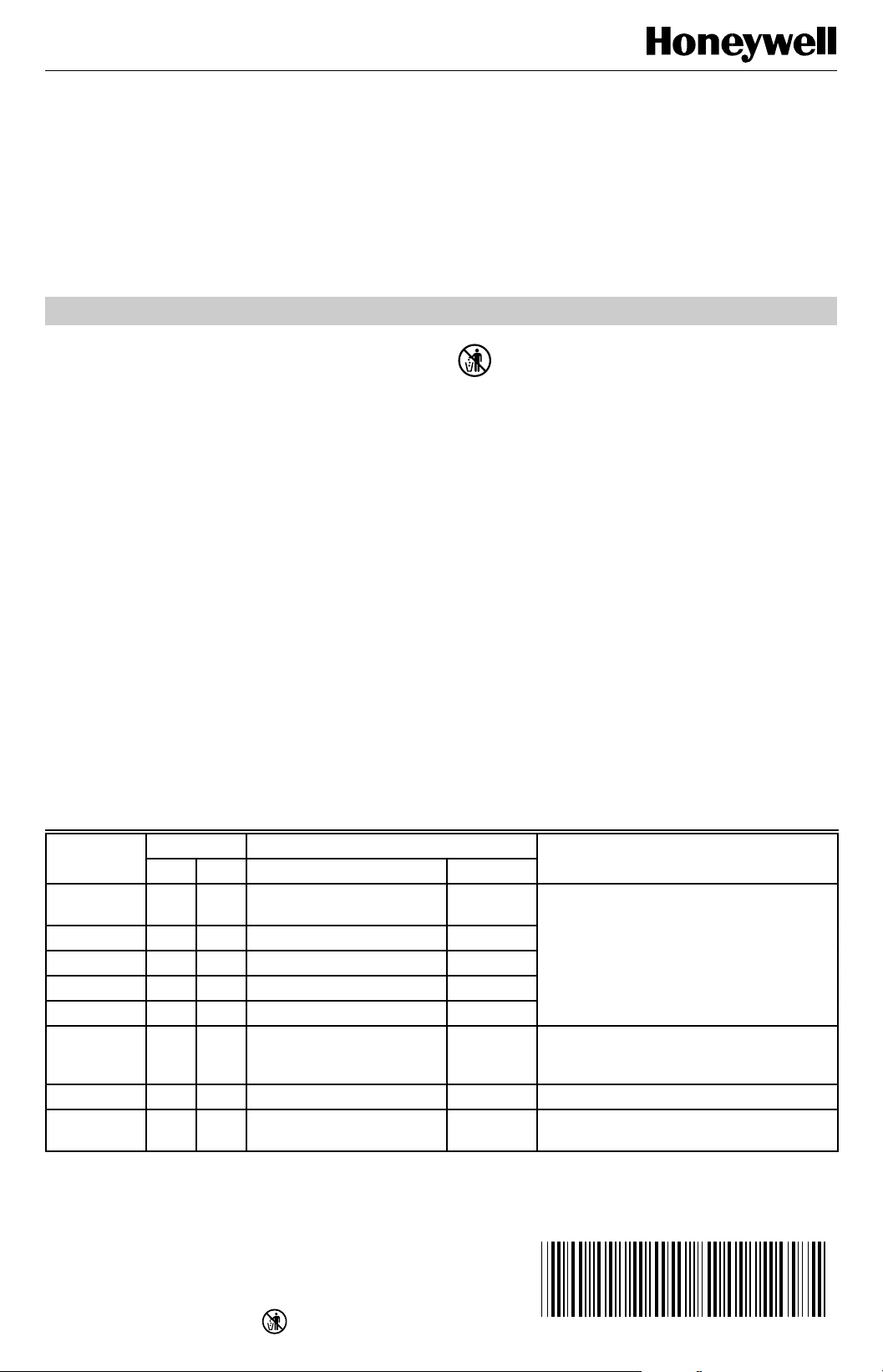
Table 1. Thermostat Models.
Stages Switching
Thermostat Heat Cool System Fan Application
T8602A 1 — — — Gas, oil or electric with independently
T8602B 1 — — ON-AUTO
T8602B 1 — HEAT-OFF —
T8602C 1 1 HEAT-OFF-COOL ON-AUTO
T8602D 1 1 HEAT-OFF-COOL-AUTO ON-AUTO
T8602C 1 1 HEAT-OFF-COOL ON-AUTO Fan operation in heating selectable for
TS8602A 1 — — — Millivolt heating system.
TS8602C
a
Available only in Canada.
a
1 1 HEAT-OFF-COOL ON-AUTO Millivolt heating and 24 Vac cooling
RECYCLING NOTICE
If this control is replacing a control that contains
mercury in a sealed tube, do
control in the trash. Contact your local waste
management authority for instructions regarding
recycling and the proper disposal of your old
control.
If you have any questions, call Honeywell Inc.
at 1-800-468-1502.
INSTALLATION
When Installing This Product…
1 Read these instructions carefully. Failure to follow
them could damage the product or cause a hazardous condition.
2 Check the ratings given on the product to make sure
the product is suitable for your application.
3 Installer must be a trained, experienced service
technician.
4 After installation is complete, check out product
operation as provided in these instructions.
5 Allow thermostat to warm to room temperature
before operating.
controlled fan.
thermostat or independent control; with O
and B terminals for changeover control.
system.
not
place your old
®U.S. Registered Trademark
Copyright © 1995 Honeywell Inc. • • All Rights Reserved
X-XX UL
T8602A,B,C,D AND TS8602A,C Chronotherm
®
III FUEL SAVER THERMOSTATS
CAUTION
Disconnect power supply to prevent electrical
shock or equipment damage.
Location
Install thermostat and wallplate about 5 ft (1.5m) above the
floor in an area with good air circulation at room
temperature.
Do not install the thermostat where it can be affected by:
— drafts or dead spots behind doors, in corners, or
under cabinets.
— hot or cold air from ducts.
— radiant heat from sun or appliances.
— concealed pipes and chimneys.
— unheated (uncooled) areas such as an outside wall,
behind the thermostat.
If Replacing An Existing Thermostat
Turn off power to the thermostat at the furnace or boiler. A
two-transformer system can require turning off two
switches or disconnects. Remove any existing wallplate or
subbase from the wall. Write down the letter or number on
each wiring terminal, as the wire is removed, to avoid
miswiring later.
If New Installation
Run cable to the hole in the selected wall location, and pull
about 3 in. (76 mm) of wire through the opening. Colorcoded, 18 gauge thermostat cable with at least one
conductor for each wiring terminal is recommended.
Push excess wire back into the hole, and plug the hole
with nonhardening caulk, putty or insulation to prevent
drafts from affecting the thermostat operation.
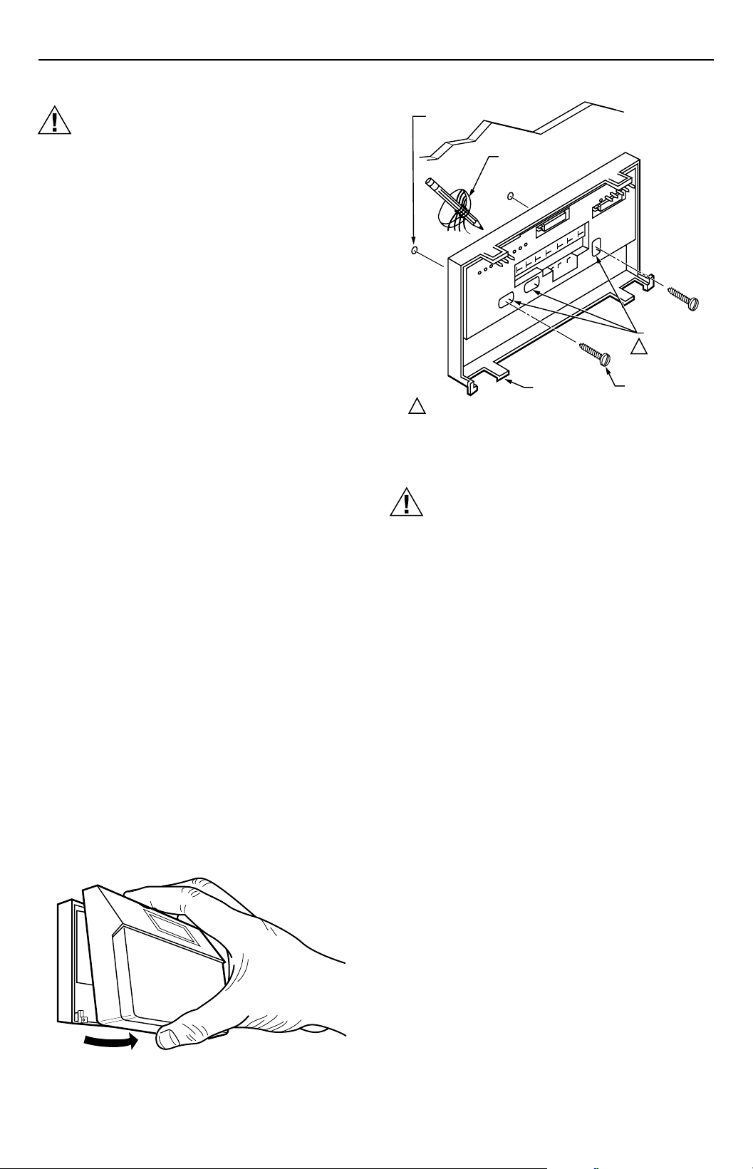
Mounting Wallplate
Remove thermostat from wallplate. See Fig. 1.
The wallplate does not require leveling for operation, but
for appearance only. The wallplate mounts directly onto
the wall with the screws included. Using the wallplate as a
template, with a pencil, mark two (of three) mounting
screw positions on the wallplate that fit the application. See
Fig. 2. Use a 3/16 in. bit to drill holes for the anchors.
Gently tap anchors into the holes until flush with the wall
surface. Thread wires through the center opening of the
wallplate. Mount the wallplate using the two screws
provided. Gently tighten the screws, level the top surface
of the wallplate, and then securely tighten the screws.
WALL
ANCHORS
(2)
WIRES THROUGH
WALL OPENING
USE TWO MOUNTING HOLES THAT
1
BEST FIT APPLICATION.
WALL
WALLPLATE
MOUNTING
HOLES (3)
1
MOUNTING
SCREWS (2)
M2917
Fig. 2. Mounting wallplate on wall.
Wiring
CAUTION
The TS8602A,C can only be used on 750 mV
heating applications. The TS8602A,C will not
function properly on 250 mV, 500 mV or 24 Vac
heating applications.
All wiring must comply with local electrical codes and
ordinances.
Disconnect power before wiring to prevent electrical shock
or equipment damage.
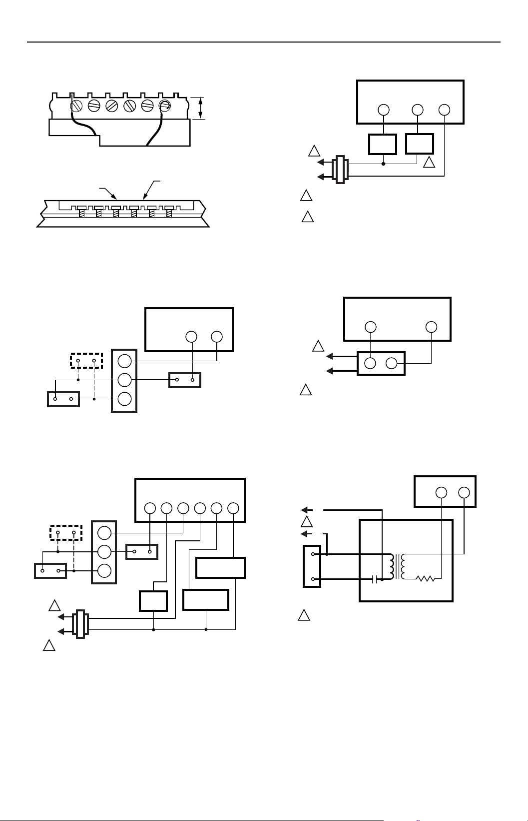
The shape of the terminal barrier permits insertion of
straight or conventional wraparound wiring connections.
Either method is acceptable.
Refer to Fig. 4 through 15 for typical wallplate and
thermostat hookups.
NOTE: • Keep all wiring restricted to the ribbed area
surrounding the terminals (Fig. 3) to assure
thermostat/wallplate contact.
• For single transformer applications, jumper
terminals R and RC for proper operation.
M2918
Fig. 1. Removing thermostat from wallplate.
69-0309—9 2
T8602A,B,C,D AND TS8602A,C Chronotherm
®
III FUEL SAVER THERMOSTATS
FOR STRAIGHT
INSERTION –
STRIP 5/16 in. (8 mm)
FOR WRAPAROUND –
STRIP 7/16 in. (11 mm)
RESTRICT
WIRING TO
THIS AREA
FRONT VIEW OF
TERMINAL AREA
WIRING TO BE BELOW
THIS SURFACE
TOP SURFACE
OF SUBBASE
CROSS-SECTIONAL VIEW OF
TERMINAL AREA
M2927
Fig. 3. Keep wiring restricted to the ribbed area
surrounding terminals.
MILLIVOLT HEATING-ONLY
WALLPLATE
PILOTSTAT
CONTROL
(IF USED)
MILLIVOLTAGE
GENERATOR
TH
TH/
PP
PP
MILLIVOLTAGE
GAS CONTROL
W
R
LIMIT
CONTROL
M2931
Fig. 4. TS8602 in typical millivoltage heating circuit.
HEATING-ONLY WALLPLATE
W
GAS
1
L2
L1
(HOT)
1
POWER SUPPLY. PROVIDE DISCONNECT MEANS
AND OVERLOAD PROTECTION AS REQUIRED.
2
MODELS WITH ON-AUTO FAN SWITCH.
VALVE
G
FAN
RELAY
R
2
M2928
Fig. 6. T8602A,B heating-only circuit in a continuous
pilot gas system.
HEATING-ONLY WALLPLATE
W
1
L1
(HOT)
L2
1
POWER SUPPLY. PROVIDE DISCONNECT MEANS
AND OVERLOAD PROTECTION AS REQUIRED.
T
T
OIL PRIMARY
R
M2929
Fig. 7. T8602A,B heating-only circuit in an oil system.
MILLIVOLT HEATING-24Vac
COOLING WALLPLATE
PILOTSTAT
CONTROL
(IF USED)
TH
TH/
PP
LIMIT
PP
CONTROL
MILLIVOLTAGE
GENERATOR
1
L1
(HOT)
L2
1
POWER SUPPLY. PROVIDE DISCONNECT MEANS
AND OVERLOAD PROTECTION AS REQUIRED.
MILLIVOLTAGE
GAS CONTROL
FAN
RELAY
G
W
R
Y O
RC
CHANGEOVER
RELAY
COOLING
CONTACTOR
M2942
Fig. 5. TS8602C in typical millivoltage heating and
24 Vac cooling circuit.
HEATING ONLY WALLPLATE
R
W
BLACK
L1
(HOT)
1
L2
BLUE
RED
RESISTANCE
HEATER
1
POWER SUPPLY. PROVIDE DISCONNECT MEANS
AND OVERLOAD PROTECTION AS REQUIRED.
BIMETAL
SWITCH
SWITCH
HEATER
RED
WHITE
R841C
M2923
Fig. 8. T8602A,B heating-only circuit in an electric
baseboard or ceiling cable system.
69-0309—93
T8602A,B,C,D AND TS8602A,C Chronotherm
®
III FUEL SAVER THERMOSTATS
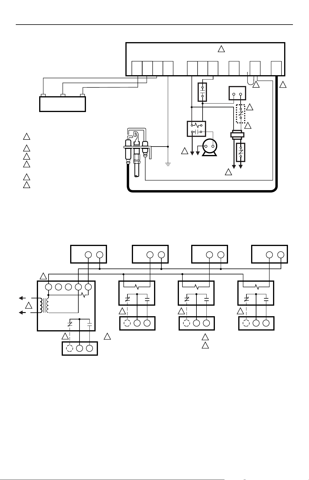
MV
DUAL VALVE COMBINATION
GAS CONTROL
POWER SUPPLY. PROVIDE DISCONNECT MEANS
1
AND OVERLOAD PROTECTION AS REQUIRED.
2
ALTERNATE LIMIT CONTROLLER LOCATION.
3
MAXIMUM CABLE LENGTH 3 FT (0.9M ).
4
CONTROLS IN 24V CIRCUIT MUST NOT BE
GROUND LEG TO TRANSFORMER.
5
LEAVE VENT DAMPER PLUG CONNECTED.
6
REMOVE JUMPER AND CONNECT SENSE
TERMINAL ON TWO ROD APPLICATION ONLY.
MV/PV
VR8345
MV
IGNITER
MV
MV/PV
PILOT GAS
SUPPLY
PV
SENSOR
GND
(BURNER)
PILOT
BURNER
GROUND
24V
GND
1
L1
(HOT)
CONTROLLER
S8610U
24V
L2
COMBUSTION
AIR BLOWER
MOTOR
5
TH-W
AIR
PROVING
SWITCH
COMBUSTION
AIR BLOWER
RELAY
VENT
DAMPER
PLUG
WR
L2
1
THERMOSTAT
4
LIMIT
CONTROLLER
L1
(HOT)
Fig. 9. T8602A,B heating-only circuit in a Honeywell Intermittent Pilot Gas Burner Ignition System.
SENSE
6
2
SPARK
3
M8600
L2
1
L1
(HOT)
2
R8239A1052
C
ZONE 1
VALVE OR
DAMPER
MOTOR
ZONE 1
HEATING ONLY WALLPLATE
W
RG
Y
W
3
R
ZONE 2
VALVE OR
DAMPER
MOTOR
ZONE 2
HEATING ONLY WALLPLATE
R
W
R8222B1067 R8222B1067
3 3 3
1
POWER SUPPLY. PROVIDE DISCONNECT MEANS
AND OVERLOAD PROTECTION AS REQUIRED.
ZONE 3
VALVE OR
DAMPER
MOTOR
ZONE 3
HEATING ONLY WALLPLATE
2
3
ZONE 4
HEATING ONLY WALLPLATE
R
W
R8222B1067
ZONE 4
VALVE OR
DAMPER
MOTOR
USE ONE R8239 FOR EVERY FOUR ZONES.
USE FOR 3-WIRE ZONE VALVE OR DAMPER.
W
M2921
R
Fig. 10. T8602A,B circuit for controlling incompatible or three-wire zone valves or dampers. Heating or cooling
equipment is operated by an end switch on the zone valve or motor, or by a thermostat in a master zone.
69-0309—9 4
 Loading...