

Page 1
HONEYWELL EXCEL 5000 OPEN SYSTEM
FEATURES
• Mountable on 2.36 in. (60 mm) wall outlet box or
• Models with setpoint adjustment.
• Models with bypass (override) button and LED.
• Models with 3-position (auto/0/1) or 5-position
• Setpoint dials with Celsius relative or Celsius absolute
T7460A,B,C,D,E,F
WALL MODULES
SPECIFICATION DATA
directly on a wall.
(auto/0/1/2/3 speed) fan switch.
scale.
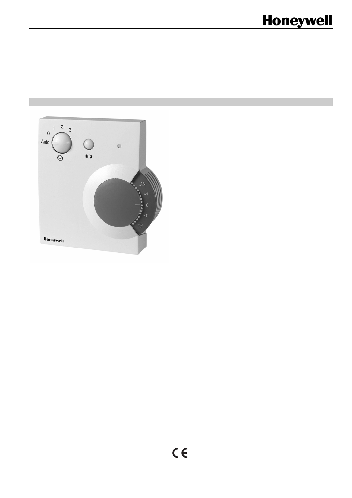
GENERAL
The T7460A,B,C,D,E,F are a family of direct-wired wall
modules for use with Honeywell Excel 10 W7750, W7751,
W7752, W7753, W7761, W7762, W7763, and Excel 600,
500, 100, 50, 20 Controllers. All models have a space
temperature sensor; some models have setpoint adjustment,
bypass button and LED, and fan switch.
• Locking cover on all models.
• Operating range 43…104°F (6…40°C).
• CE-approved.
• IP 30 housing.
DESCRIPTION
The T7460A,B,C,D,E,F packages include two setpoint dials.
By default, the “Celsius Relative” type (-5 … +5) is mounted,
but can be easily replaced with the “Celsius Absolute” type
(12…30°C).
® U.S. Registered Trademark
Copyright © 2005 Honeywell Inc. • All Rights Reserved 74-3083-2
Page 2
T7460A,B,C,D,E,F WALL MODULES
F
t
r
resis
t
ohms
SPECIFICATIONS
Table 1. T7460 Wall Module models
type no. setpoint adjustment
bypass
T7460A -- -- --
T7460B -- --
T7460C 3 --
12…30 °C (absolute)
T7460D -- 5
T7460E 3 3
T7460F
NOTE: Not all of the T7460 Wall Modules are compatible with W7751A,C,E,G (VAV1) and W7752D1 (FCU1) controllers.
NOTE: Refer to T7460A,B,C,D,E,F Installation Instructions (product literature no.: EN1B-0291GE51) for wall module settings
and wiring diagrams.
Construction:
Two-piece construction: cover and internally wired subbase.
Field wiring 16 to 22 AWG (1.5 to 0.34 mm
terminal block on the PCB.
Temperature Sensor Operating Range:
43…104°F (6…40°C).
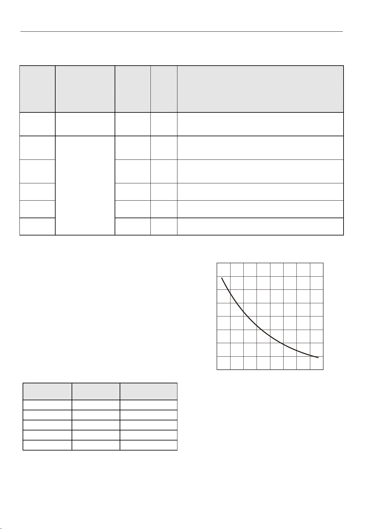
T7460A,B,C,D,E,F 20kΩ Sensor:
All T7460 models are furnished with a 20kΩ NTC temperature
sensor following a specific temperature-resistance curve. See
Fig. 1. Honeywell controllers used with the T7460 employ an
algorithm that provides readings close to the actual
temperature. Table 2 summarizes the T7460 sensor accuracy
for normal operating temperatures. Throughout the range of
43…104°F (6…40°C), the accuracy is better than ±0.75°F
(±0.42°C).
Table 2. Temperature sensor accuracy
ambient temp.
°F (°C)
60 (15.5) ±0.52 (±0.29) 31543
65 (18.3) ±0.49 (±0.27) 27511
70 (21.1) ±0.48 (±0.27) 24047
80 (26.7) ±0.49 (±0.27) 18490
85 (29.5) ±0.52 (±0.29) 16264
± 5 K (relative)
max. error
°F (°C)
LED
(override)
button and
3 5
2
) connects to a
nom. resistance
(Ω)
3- or 5-
position
fan switch
W7750A,B, W7751B,D,F,H, W7752D,E,F,G, W7753A, W7761A,
W7762A,B, W7763C,D,E, and
Excel 600, 500, 100, 50, 20
W7750A,B, W7751B,D,F,H, W7752D,E,F,G, W7753A, W7762B,
W7763E, and
Excel 600, 500, 100, 50, 20
W7750A,B, W7751B,D,F,H, W7752D,E,F,G, W7753A,
W7762A,B, W7763D,E, and
Excel 600, 500, 100, 50, 20
W7752D,E,F,G, W7753A, and
Excel 600, 500, 100, 50, 20
W7750A,B, W7752D,E,F,G, W7753A, and Excel 600, 500, 100,
50, 20
W7752D,E,F,G, W7753A, and
Excel 600, 500, 100, 50, 20
80 K
70 K
)
60 K
50 K
ance (
40 K
30 K
ical
20 K
elec
10 K
30
0 10 20 30 40
Fig. 1. Temperature vs. resistance for 20kΩ sensor
T7460B,C,D,E,F Setpoint Adjustment:
In the case of wall modules equipped with setpoint adjustment, depending on the type of setpoint dial in use, the controller must be set for either the relative or the absolute scale.
The relation between setpoint and resistance is given in Table
3. Accuracy of resistance is:
• ±5% in middle position, e.g. 5225 Ω to 5775 Ω;
• ±10% in end position, e.g. 9450 Ω to 11550 Ω.
compatible with
40 50 60 70 80 90 100 110
temperature (degrees)
°
°C
74-3083-2 2
Page 3

T7460A,B,C,D,E,F WALL MODULES
Table 3. Setpoint values versus resistances
relative scale (Kelvin) absolute scale (°C)
setpoint
nominal
resistance (Ω)
setpoint
nominal
resistance (Ω)
-5 9574.0 12 9958.0
-4 8759.2 13 9468.7
-3 7944.4 14 8979.3
-2 7129.6 15 8490.0
-1 6314.8 16 8000.7
0 5500.0 17 7511.3
1 4685.2 18 7022.0
2 3870.4 19 6532.7
3 3055.6 20 6043.3
4 2240.8 21 5554.0
5 1426.0 22 5064.7
23 4575.3
24 4086.0
25 3596.7
26 3107.3
27 2618.0
28 2128.7
29 1639.3
30 1150.0
T7460C,E,F Bypass Button / LED
When Used With Excel 10 Controllers:
The controller provides timed occupied and unoccupied
temperature setpoints for the wall module, see Fig. 2. The
bypass button is used to change the controller into the modes
shown in Table 4 and Fig. 3. The override LED displays the
override status of the controller.
Table 4. Bypass button/LED operation
1b button held
down
controller mode LED status
0…1 sec no override OFF
1…4 sec
timed occupied
override
ON
4…7 sec unoccupied override 1 blink / sec
>7 sec no override OFF
--
continuous occupied
overridea
2 blinks / sec
-- wink from networka 4 blinks / sec
2b controller mode
independent of bypass button
LED status
Effective Occupied / Effective Bypass ON
Effective Standby 1 blink / sec
Effective Unoccupied OFF
Wink from network 4 blinks / sec
a
Remote function. Generated from the network.
b
1=Controller configured for indicating override;
2=Controller configured for indicating occupancy
PRESS
for <1 sec
RESET
NOT ASSIGNED
(LED OFF)
PRESS
for 1...4 sec
BYPASS OCCUPIED
(LED ON)
BYPASS
TIME-OUT
PRESS
for 4...7 sec
PRESS
for <1 sec
UNOCCUPIED
(LED BLINKS)
PRESS
for >7 sec
Fig. 3. Bypass button operation (with Excel 10)
When Used With Excel 600/500/100/50/20 Controllers:
All Excel 600, 500, 100, 50, and 20 Controllers are fully
programmable. The application engineer-programmer can
Fig. 2. LED and bypass button locations on T7460C,E,F
program the override and LED to operate in any manner
desired. The bypass (override) input is a dry-contact,
normally-open, momentary digital input when the wall module
does not have a fan switch. When a fan speed switch
(basically a series of resistances based on fan switch
position) is present, the bypass button is an analog input. See
Table 5 for those resistances.
Every controller includes a software module (XFM) enabling
you to adapt the wall module to the respective controller,
making further configuring unnecessary.
Contact your local Honeywell distributor for further details.
3 74-3083-2
Page 4

T7460A,B,C,D,E,F WALL MODULES
T7460D,E,F Fan Switch
When Used With Excel 10 FCU Controller:
The T7460D,F have a 5-position fan switch (Auto, 0, 1, 2, 3);
the T7460E has a 3-position fan switch (Auto, 0, 1).
Fan runs automatically at the speed determined
by the controller’s temperature control algorithm.
Fan is continuously off.
Fan is continuously running at speed 1.
Fan is continuously running at speed 2.
(Not available with T7460E).
Fan is continuously running at speed 3.
(Not available with T7460E).
NOTE: The fan speed switch on the wall module overrides
the temperature control algorithm.
When Used With Excel 600/500/100/50/20 Controllers:
All the Excel 600, 500, 100, 50, and 20 Controllers are fully
programmable and can be programmed so that the fan speed
switch and bypass button function the way that the application
engineer/programmer wants. The resistances used for
programming the controller are shown in Table 5.
Every controller includes a software module (XFM) enabling
you to adapt the wall module to the respective controller,
making further configuring unnecessary.
Contact your local Honeywell distributor for further details.
Table 5. Program settings for wall modules with fan
switch
for switch position resistance (Ω)
Auto 1861.4 ±100
0 2686.4 ±100
Mounting Options:
Dimensions (H/W/D):
Environmental Ratings:
Relative Humidity:
5% to 95% non-condensing.
Approvals:
ACCESSORIES
For mounting the following accessories, see
T7460A,B,C,D,E,F Installation Instructions (product literature
no.: EN1B-0291GE51).
T7460-LONJACK
The T7460-LONJACK is a small board and allows easy
access to L
must be already connected, in compliance with the max.
cable lengths set forth by the L
L
ONWORKS network via a LONWORKS bus cable). Via an
additional 3.5 mm jack plug on the board, a PC connection
can be established.
Order quantity: set of 5 pieces
T7460-LIMITER
The T7460-LIMITER can be used to adjust the setpoint dial to
particular setpoints.
Order quantity: set of 100 pieces
See T7460A,B,C,D,E,F Installation Instructions
(product literature no.: EN1B-0291GE51) for jumper
settings.
The T7460 can be mounted on a 60 mm diameter junction
box or directly on a wall.
4-1/8 x 3-15/16 x 1-3/16 in. (104 x 99 x 30 mm).
Operating temperature: 43° to 104°F (6° to 40°C).
Shipping temperature: -40° to 150°F (-40° to 65°C).
CE.
ONWORKS via the wall module (the wall module
ONWORKS Guidelines, to the
1 3866.4 ±100
2 3041.4 ±100
3 4601.4 ±100
bypass button closed 0 to 100
NOTE: An additional 10kΩ (±2%) series resistor can be set
by jumper (jumper setting: A=1; B=3).
Manufactured for and on behalf of the Environmental and Combustion Controls Division of Honeywell Technologies Sàrl, Ecublens, Route du Bois 37, Switzerland by its Authorized Representative:
Automation and Control Solutions
Honeywell GmbH
Böblinger Straβe 17
D-71101 Schönaich
Phone xx49-(0)7031-637-01
Fax xx49-(0)7031-637-493
http://europe.hbc.honeywell.com
74-3083-2 rev. 10-05 Printed in Germany
 Loading...