

Page 1
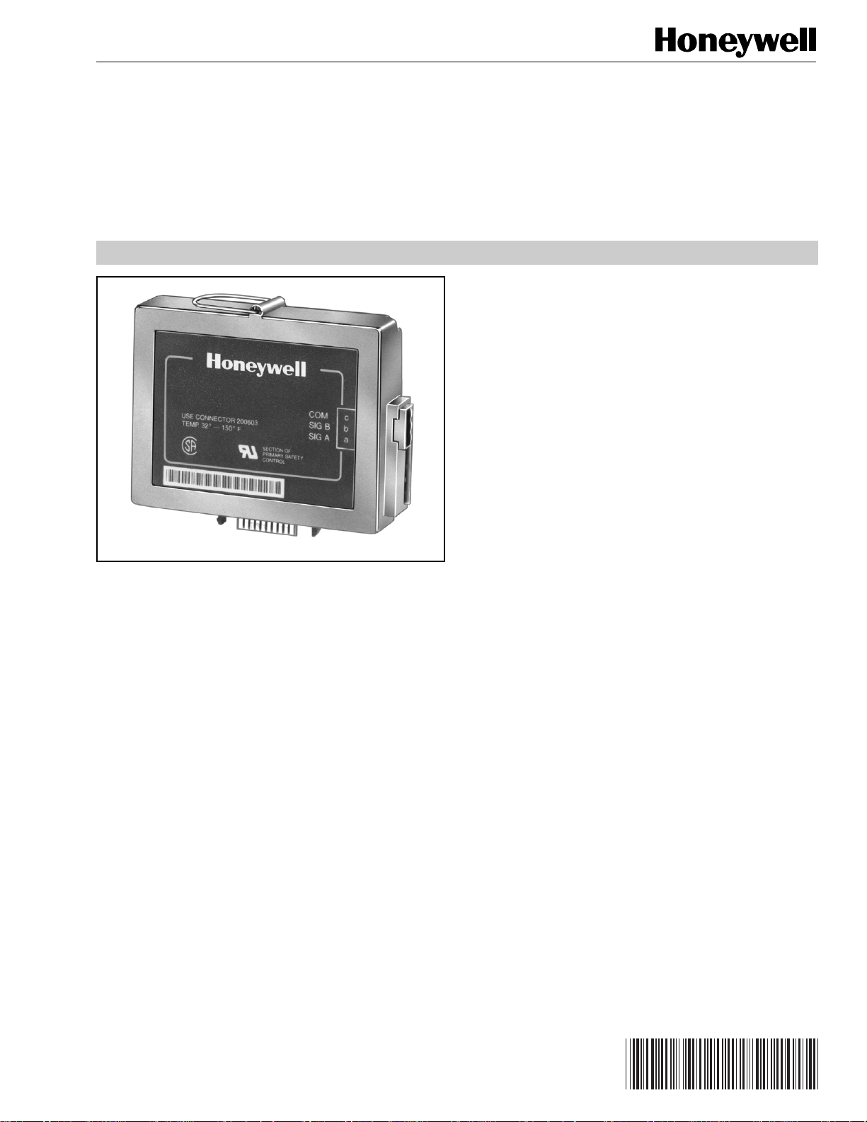
SYSNet™ QS7700A Network Interface
63-2284-2
ControlBus™ Module for BCS7700
PRODUCT DATA
FEATURES
• Up to six ControlBus™ Modules per Network Interface
Unit.
• Remote programming of nonsafety BCS 7700 values
via the ControlBus™ Modules.
• Local and remote annunciation of BCS 7700 faults.
•Personal computer user interface.
• Modular construction.
• Microsoft Windows™ based Combustion System
Manager® user interface.
• Microsoft Windows™ based SYSNet™ Operator user
interface.
APPLICATION
The SYSNet™ QS7700A Network Interface ControlBus™
Module allows remote programming, control, monitoring and
diagnostics of the Boiler Control System (BCS) 7700.
Contents
Application .......................................................................... 1
Features .............................................................................. 1
Specifications ...................................................................... 2
Ordering Information ........................................................... 2
Installation ........................................................................... 3
Wiring .................................................................................. 3
® U.S. Registered Trademark
Copyright © 1996 Honeywell Inc. • All Rights Reserved
X-XX UL
Page 2

SYSNet™ QS7700A NETWORK INTERFACE ControlBus™ MODULE
SPECIFICATIONS
Models:
QS7700A1011 Network Interface ControlBus™ Module for
use with the BCS 7700 and Q7700A1014 and
Q7700B1004 Network Interface Unit.
Electrical Ratings:
ControlBus™ Communication.
Current Draw: 75 mA.
Electrical Connectors:
ControlBus™ Three-Prong Electrical Connector.
Environmental Ratings:
Ambient Temperature:
Operating: 32°F to 130°F (0°C to 54°C).
Storage: -30°F to +150°F (-34°C to +66°C).
Humidity: Operating 85 percent relative humidity,
continuous, noncondensing.
Vibration: Continuous 0.5G.
Enclosure: NEMA 1.
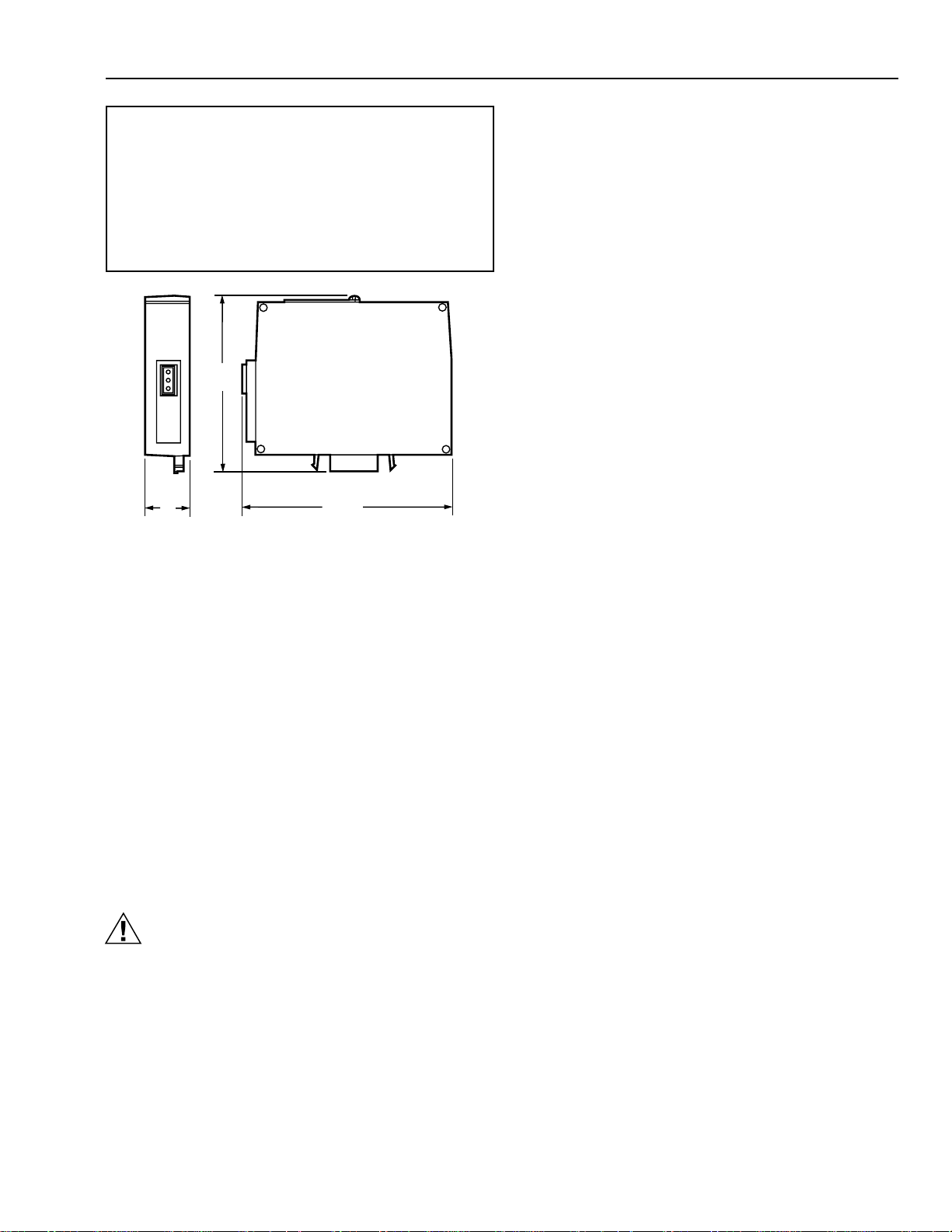
Dimensions:
See Fig. 1.
Weight:
8 oz (unpacked).
Accessories:
221237/1698 Cover Assembly, Q7700 Network Interface
Unit.
221240/1698 Cover Assembly, Q7700 Electrical
Enclosure, Network Interface Unit.
202433 Slot Inserts, ControlBus™ Slots Base Unit.
200603 ControlBus™ Electrical Connector.
Approvals:
Underwriters Laboratories Inc, File No. MP268,
Guide No. MCCZ2.
Canadian Standards Association LR80141 .
Federal Communications Commission, Part 15, Class A
Emissions, Part 68.
FCC Registration Number HS92SJ-10735-DT-E.
Canadian Department of Communication CS-03,
Certification Number 573-3459A.
IMPORTANT
This equipment complies with the requirements in
part 15 of FCC rules for a Class A computing device.
Operation of this equipment in a residential area can
cause unacceptable interference with radio and
television reception that requires the operator to take
whatever steps are necessary to correct
interference.
WARNING
This equipment generates, uses, and can radiate
radio frequency energy, and if not installed and used
in accordance with the Instructions Manual, may
cause interference with radio communication. It has
been tested and found to comply with the limits for a
Class A computing device pursuant to Subpart J of
Part 15 of FCC Rules, which are designed to provide
reasonable protection against such interference when
operated in a commercial environment. Operation of
this equipment in a residential area is likely to cause
interference, in which case, users at their own
expense will be required to take whatever measures
may be required to correct the interference. Any
unauthorized modification of this equipment may
result in the revocation of the owner’s authority to
continue its operation.
ORDERING INFORMATION
When purchasing replacement and modernization products from your TRADELINE® wholesaler or distributor, refer to the
TRADELINE® Catalog or price sheets for complete ordering number, or specify:
1. Model number
2. Application
If you have additional questions, need further information, or would like to comment on our products or services, please write or
phone:
1. Your local Home and Building Control Sales Office (check white pages of your phone directory).
2. Home and Building Control Customer Logistics
Honeywell Inc., 1885 Douglas Drive North
Minneapolis, Minnesota 55422-4386
In Canada—Honeywell Limited/Honeywell Limitée, 35 Dynamic Drive, Scarborough, Ontario M1V 4Z9.
International Sales and Service Offices in all principal cities of the world. Manufacturing in Australia, Canada, Finland, France,
Germany, Japan, Mexico, Netherlands, Spain, Taiwan, United Kingdom, U.S.A.
63-2284—2
2
Page 3
SYSNet™ QS7700A NETWORK INTERFACE ControlBus™ MODULE
Canadian EMI: This digital apparatus does not exceed the
Class A limits for radio noise emission from digital apparatus
set out in the
Canadian Department of Communications.
Le présent appareil numérique n’émet pas de bruits
radioélectriques dépassant les limites applicables aux
appareils numériques de la Classe A prescrites dans le
Règlement sur le brouillage radioeléctrique édicté par le
ministère des Communications du Canada.
Fig. 1. QS7700A Network Interface ControlBus™
Radio Interference Regulations
3-29/32
(99)
1
(25)
Module dimensions in in. (mm).
4-21/32
(118)
of the
M2093
INSTALLATION
When Installing this Product...
1. Read these instructions carefully. Failure to follow them
could damage the product or cause a hazardous
condition.
2. Check the ratings given in the instructions and on the
product to make sure the product is suitable for your
application.
3. Installer must be a trained, experienced service
technician.
4. Check out the product after installation, as provided in
the Q7700 Network Interface Unit instructions,
form 63-2278.
5. Make sure that repairs are made only by the
manufacturer.
6. If trouble develops, disconnect the equipment from the
modem and determine the cause of the fault.
Reconnect only when the problem is corrected.
CAUTION
1. Disconnect power supply before beginning
installation to prevent electrical shock and
equipment damage. More than one power supply
disconnection can be involved.
2. Wiring must comply with all applicable codes,
ordinances and regulations.
3. Refer to Fig. 6 for proper system wiring.
4. Do not plug or unplug any Network Interface Unit
ControlBus™ Module or electrical connectors
with the power on. Make sure that power is off to
protect against equipment damage.
Humidity
Install the Network Interface Unit where the relative humidity
never reaches the saturation point. The Network Interface
Unit is designed to operate in an 85 percent relative humidity
continuous noncondensing moisture environment.
Condensing moisture can result in improper operation.
Vibration
Do not install the Network Interface Unit where it can be
subjected to excessive vibration in excess of 0.5G
continuous maximum vibration.
Weather
The Network Interface Unit is not designed to be weather
tight. If installed outdoors, the Network Interface Unit must be
protected.
Mounting the Network Interface Plug-in Card
NOTE: For installation dimensions, see Fig. 1.
Mount the ControlBus™ Module in the Network
Interface Unit (see Fig. 2). Do
Interface Unit with the Network Interface Unit edge
connector slots facing
Insert the ControlBus™ Module with the electrical
connector facing out from the Network Interface Base
Unit.
Grasp the ControlBus™ Module and align the plug-in
edge card with the connector in the bottom of the
Network Interface Unit.
Firmly insert the ControlBus™ Module into the Network
Interface Unit.
Select a location that can support the Network Interface
Unit. Be sure to allow clearances for servicing,
installation and removal of the wiring compartment
cover, Network Interface Unit cover, electrical
connectors and ControlBus™ Modules.
a. Allow for an additional 2-1/2 inches (64 mm)
minimum below the Network Interface Unit for
electrical connector installation.
b. Allow for an additional 1-1/2 inches (38 mm)
minimum on each side for electrical housing
cover insertion and wiring.
Remove the ControlBus™ Module by using the wire
loop and grasping the Wire loop firmly and pulling the
module from the Network Interface Unit.
down
not
mount the Network
.
WIRING
Wiring Requirements
1. All wiring must comply with all applicable electrical
codes, ordinances, and regulations.
2. Recommended wire size and type for ControlBus™
communication; terminal identification numbers are
noted within brackets:
1 [A]
2 [B]
3 [C]
3
63-2284—2
Page 4

SYSNet™ QS7700A NETWORK INTERFACE ControlBus™ MODULE
3. Recommended wiring for ControlBus™ Module for
communications routing purposes is unshielded 22 AWG,
two-wire twisted cable and one wire for ground, if the
leadwire run and noise conditions permit. If necessary,
Belden 8771 shielded cable or equivalent can be used.
Be aware that the BCS7700 chassis module must be at
one end of the daisy chain and the module on the
farthest end of the daisy chain configuration string require
a 120 ohm, 1/4 watt (minimum) resistor termination
across terminals 1 and 2 of the electrical connectors.
See Fig. 6.
a. Do not route the ControlBus™ cable in conduit
with line voltage circuits.
b. Do not route the ControlBus™ cable close to the
ignition transformer.
c. Route the ControlBus™ cable outside of conduit
if properly supported and protected from damage.
d. Route the ControlBus™ cable so that all devices
are connected in a daisychain(A-A, B-B, C-C).
The BCS 7700 Chassis Module must be at one
end of the daisy chain configuration string. The
interconnection of all other devices is not
important, except that the device at the distant
end of the daisy chain configuration string must
be terminated with a 120 ohm, 1/4 watt resistor
between terminals A and B.
4. Maximum wire lengths can be 4000 ft (1219m) for the
ControlBus™ RS-485 interface under ideal conditions.
Procedure
Refer to Fig. 6 for proper wiring.
Be sure that power is removed from the control panel
by opening the main disconnect before beginning wiring
to the electrical connectors. More than one
disconnection can be involved.
Select the location of the Network Interface Unit to be
mounted:
a. Near a phone line.
b. Within 4000 ft (1219m) of all BCS 7700s that will
be connected to the Network Interface Unit.
c. Within 50 ft (15m) of the personal computer that
will be connected to the 25-pin RS-232 port of the
Mount the Network Interface Unit and insert the
Route the ControlBus™ cable so that all devices are
Connect L1, L2 and Ground (GND) to the pigtails
Connect the 5-pin DIN connector cord, from the
Network Interface Unit.
ControlBus™ Module into the Network Interface Unit
slot, see Fig. 2 and 5.
connected in a daisychain (A-A, B-B, C-C). The BCS
7700 Chassis Module must be at one end of the daisy
chain configuration string. The interconnect of all other
devices is not important, except that the device at the
distant end of the daisy chain configuration string must
be terminated with a 120 ohm, 1/4 watt resistor
between terminals A and B. Remove any other
termination resistors and install a 120 ohm, 1/4 watt
resistor at the final device in the string.
(Q7700A
only
).
switching power supply, to the 5-pin DIN conctor on the
Network Interface Unit. Connect the IEC power cord,
from the switching power supply, to a line voltage
source (Q7700B only).
Insert the plug-in card slots into any open slots of the
Network Interface Unit.
Install the covers, power wiring compartment and
Network Interface Unit.
쐅 Connect the serial port of the modem to the 9-pin
RS-232 connector of the Network Interface Unit
(see Fig 4).
쐈 Connect the serial port of the personal computer to the
25-pin RS-232C port on the Network Interface Unit for
local personal computer application, see Fig. 3.
쐉 Do not exceed 600 mA current draw, six card
maximum, total capacity of the plug-in cards. Refer to
the ControlBus™ Module device label and this
specification for individual loads.
씈 Check all wiring with Fig. 6 before installing an
electrical connector.
씉 Install all electrical connectors.
씊 Restore power to the Network Interface Unit.
NETWORK
INTERFACE
UNIT
CONTROLBUS
MODULE
ELECTRICAL
CONNECTOR
EDGE
CONNECTOR
M7437B
Fig. 2. ControlBus™ Module mounting.
NETWORK
INTERFACE
UNIT
25-PIN
RS-232C
CONNECTOR
M7432B
Fig. 3. RS-232 Interface insertion
(serial communications).
63-2284—2
4
Page 5

9-PIN RS-232
CONTROLBUS
MODULE
CONTROLBUS
RS-485 CONNECTOR
NETWORK
INTERFACE UNIT
M7436B
CONNECTOR
SYSNet™ QS7700A NETWORK INTERFACE ControlBus™ MODULE
NETWORK
INTERFACE UNIT
CONTROLBUS™
PLUG-IN MODULE
RS-232C CONNECTOR
(SERIAL COMMUNICATIONS)
M7433B
Fig. 4. Modem insertion, Network Interface Unit.
NETWORK INTERFACE UNIT
PLUG-IN PLUG-IN
3
120 OHM
6
UNIVERSAL
POWER
SUPPLY
1
120V
60 Hz
POWER
SUPPLY
L1
L2
GND
2
1/4 WATT
A
B
A
B
C
4
KEYBOARD AND
C
DISPLAY
Fig. 5. ControlBus™ RS-485 interface insertion.
5
SYSTEM 2
CHASSIS
C
B
A
1
POWER SUPPLY. PROVIDE DISCONNECT MEANS AND OVERLOAD PROTECTION AS REQUIRED:
Q7700A:120VAC, 50/60 HZ; Q7700B: 100-250VAC, 50/60 HZ UNIVERSAL POWER SUPPLY.
2
CONNECT PIGTAIL LEADWIRES: (Q7700A ONLY)
BLACK—L1
WHITE—L2
GREEN—GROUND
3
4
5
6
THE SYSTEM CONTROLBUS™ MUST BE ROUTED SO THAT ALL DEVICES ARE CONNECTED DAISY CHAIN CONFIGURATION (A-A, B-B, C-C).
THE SYSTEM CHASSIS AND PROGRAM MODULES MUST BE AT ONE END OF THE STRING, THE INTERCONNECTION OF DEVICES IS NOT
IMPORTANT, EXCEPT THE DEVICE ON THE FARTHEST END OF THE DAISY CHAIN CONFIGURATION STRING MUST BE TERMINATED
WITH A 120 OHM 1/4 WATT RESISTOR BETWEEN TERMINALS A AND B, REMOVE ANY OTHER TERMINATION RESISTORS.
THREE-WIRE SHIELDED CABLE REQUIRED FOR CONNECTIONS MORE THAN 100 FEET. CABLE SHIELD MUST BE TERMINATED TO
EARTH GROUND. IF SHIELDED CABLE IS NOT USED, TWISTED PAIR WIRE MUST BE USED.
UP TO SIX SYSTEMS CAN BE INTERFACED WITH THE NETWORK INTERFACE UNIT. EACH SYSTEM MUST RESIDE ON
A SEPARATE CONTROLBUS. NO TWO SYSTEMS SHOULD RESIDE ON ONE CONTROLBUS.
FOR Q7700B.
Fig 6. Network Interface wiring.
5
M1456B
63-2284—2
Page 6

SYSNet™ QS7700A NETWORK INTERFACE ControlBus™ MODULE
63-2284—2
6
Page 7

SYSNet™ QS7700A NETWORK INTERFACE ControlBus™ MODULE
7
63-2284—2
Page 8

SYSNet™ QS7700A NETWORK INTERFACE ControlBus™ MODULE
Home and Building Control
Honeywell Inc.
Honeywell Plaza
P.O. Box 524
Minneapolis MN 55408-0524
Home and Building Control
Honeywell Limited-Honeywell Limitée
155 Gordon Baker Road
North York, Ontario
M2H 2C9
Honeywell Asia Pacific Inc.
Room 3213-3225
Sun Hung Kai Centre
No. 30 Harbour Road
Wanchai
Hong Kong
Honeywell Latin American Division
Miami Lakes Headquarters
14505 Commerce Way Suite 500
Honeywell Europe S.A.
3 Avenue du Bourget
B-1140 Brussels Belgium
Miami Lakes FL 33016
Helping You Control Your World
63-2284—2 G.R. Rev. 7-96 Printed in U.S.A. www.honeywell.com/bbc
63-2284—2
8
 Loading...