

Page 1
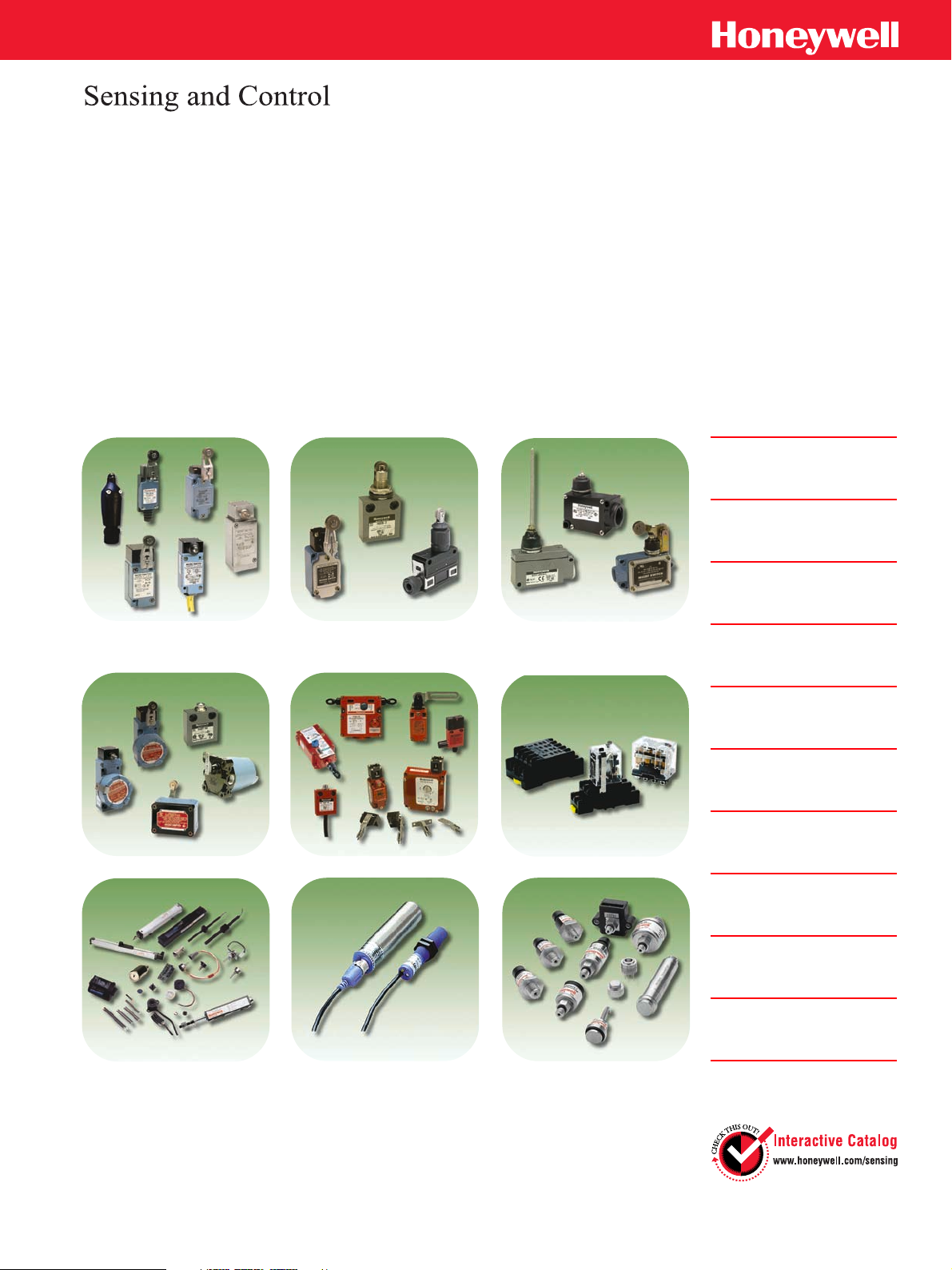
Industrial
Switches
and
Product solutions on the Interactive Catalogue
Sensors
Global switches
Heavy duty switches
Compact switches
Precision switches
Hazardous location switches
Safety switches
Relays
Position products
Ultrasonic distance sensors
Pressure sensors
July 2003
Page 2

Inside front
cover
WARNING
!
PERSONAL INJURY
DO NOT USE these products* as safety or emergency stop
devices, or in any other application where failure of the
product could result in personal injury.
*
Does not apply to 24CE/924CE Series (page 23), GSS Series
(page 80), GK Series (pages 78, 83, 85) or CPS Series (page 89)
Failure to comply with these instructions could result in
death or serious injury.
WARNING
!
MISUSE OF DOCUMENTATION
• The information presented in this product sheet (or
catalogue) is for reference only. DO NOT USE this
document as product installation information.
• Complete installation, operation and maintenance
information is provided in the instructions supplied with
each product.
Failure to comply with these instructions could result in
death or serious injury.
2
www.honeywell.com/sensing
Page 3

CONTENTS
Introduction - How to use this catalogue
EVN2000 Series
Fast Install Limit Switches
A recent addition to our range. Saves over 50 % in installation
time with a design that eliminates the need to gain access to the
inside of the housing in order to connect the switch.
SZL-VL Series
Limit Switches
New, economic, compact, rugged, dependable limit switches.
GL Series EN50041/47
Global Limit Switches
A complete range of CENELEC approved products,
suitable for most industrial applications.
SL1 Series
Space saving size for machine miniaturization,
different contact and actuators available.
14/914CE Series
Miniature Enclosed Switches
Miniature, rugged, pre-wired switches, meeting the requirements
of the Low Voltage directive. They come with a range of head
styles and sealing options.
Page 2
Page
Page
Page
Page
Page
HDLS Series
Heavy Duty Limit Switches
Suitable for special applications in corrosive environments. Housed
in a rugged die-cast zinc body and epoxy coated for protection,
they are available with a range of switching and head options.
Explosion Proof Switches
A range of switches designed for use in hazardous applications
in potentially explosive atmospheres. Most are UL-CSA listed and
some meet the requirement of the new European Directive 94/9/EC
(commonly referred to as the ATEX Directive).
Levers for Limit Switches
A range of levers for use with Honeywell’s Limit Switches.
Select the best one for your application.
Safety Switches for machine guarding
Safety interlock switches, limit switches and cable-pull limit
switches for industrial machine safety.
Relays
Designed for a wide range of applications including power as
well as logic control for factory machines and control panels.
Linear and Rotary Position
A wide selection of Hall-effect, magnetoresistive, and
potentiometric devices for detecting the presence of a magnetic
field or linear and rotary position.
Page
Page
Page
Page
Page
Page
24/924CE Series
Miniature Enclosed Switches
Miniature, rugged, direct opening action contacts. This switch
is available with a variety of actuators and is pre-wired.
LS Series
Compact Limit Switches
A range of compact limit switches designed for accurate
repeatability under the most stringent conditions. Special oil
resistant and high temperature versions are available.
BF Series
Medium Duty Limit Switches
Rugged plastic enclosure, with large internal cavity for ease of wiring.
BZE/DTE Series
Medium Duty Limit Switches
Side or flange mount, momentary or maintained contact, sealed
or unsealed actuators, removal of bottom enclosure for ease of wiring.
BAF/DTF Series
High Capacity Enclosed Switches
Rugged cast aluminium housed switches, sealed for
wash-down applications. Momentary or maintained contacts,
right or left hand actuators, 3 hole mounting.
Page
Page
Page
Page
Page
Opto Sensors
Ultrasonic Distance Sensors
Ultrasonic position sensors for presence/absence sensing,
precision distance sensing or tracking for areas where other
sensing technologies have difficulty, such as clear or
shiny objects, foggy or particle laden air, or splashing liquids.
Pressure sensors
We offer stainless steel and silicon pressure sensors depending
on the application, as well as a variety of high purity pressure sensors.
Honeywell Sensing and Control products
Index
Page
Page
Page
Page
Page
www.honeywell.com/sensing
1
Page 4

INTRODUCTION
HONEYWELL INDUSTRIAL SWITCHES AND SENSORS
Honeywell Industrial Switches and Sensors provide a wide selection of products and technologies for applications in most industrial applications. This catalogue
contains our most popular listings. To view our complete range of products, visit our website at http://www.honeywell.com/sensing.
Honeywell is a worldwide leader in advanced switching and sensing technology. Our reputation for technology, quality and reliability is second to none. We have
more than 60 years of experience; and extensive knowledge of Industrial applications, an extensive customer service and support network. Honeywell
manufactures the original MICROSWITCH brand switch and we offer one of the most complete lines of global electro-mechanical heavy duty limit switches.
Sealed versions keep out moisture and other contaminates. Explosion proof types are designed for use in hazardous locations. Safety versions provide direct
opening action contacts for machine guarding and emergency stops.
We are a recognized technology leader in the development and manufacture of pressure and position-sensing transducers and controls. We use the latest in
manufacturing technology to produce hundreds of thousands of transducers a year. Millions of units are currently performing in a multitude of continuous-duty
applications around the world, where they typically outlast the systems they support. We have ISO 9001 certified facilities and Class 10 cleanroom capability, and
we manufacture a full line of high purity pressure sensing and control products; each individually tested, inspected and certified to be in full compliance with the
product specification.
A comprehensive and diverse line of speed and position sensors for the Industrial market place is also available. With the combined capabilities of three wellknown product brands - Data Instruments, Clarostat, Electro and New England Instruments - Honeywell continuously strives to solve customers’ application
problems. Whether you need custom designed sensors for proprietary OEM applications or off-the-shelf sensor solutions, our extensive in-house design,
manufacturing and environmental testing capabilities offer solutions and alternatives to meet your needs.
2
www.honeywell.com/sensing
Page 5
INTRODUCTION
How to use this catalogue
For each referenced listing, key specification parameters, descriptions and
mounting drawing information are presented. These illustrate our capabilities
while the specifications include allow easy differentiation between similar
products.
There are, of course, many more product options available. Full product
specification may be accessed on our website (www.honeywell.com/sensing).
At the Home page enter the catalogue listing reference in the SEARCH box and
click GO! This will take you directly to the interactive catalogue/specification
search tables for this listing. Alternatively select and click the interactive
catalogue icon on the Home page and then choose a product category against
which to do a specification search.
Also on the website you can access installation instructions, application notes,
Frequently Asked Questions (FAQs), selection guides and additional technical
information.
Mounting dimensions
Mounting dimensions shown in each product section are for reference only.
For exact information, request an engineering drawing from you nearest
Honeywell sales office or visit our website and access it through the interactive
catalogue. Where dual dimensions are shown on mounting drawings, the first
or upper one is millimetres (mm) and the second or lower is inches (in).
Where single dimensions are shown, they are millimetres (mm), unless
otherwise stated.
To order these products
Simply contact your local Honeywell Sales Representative, your Honeywell
Distributor or your local Honeywell office.
If you need a product not listed in this catalogue
One of Honeywell’s strengths is in application-specific packaging of sensing
technology. Honeywell provides many variations of our basic switches and
sensors. For more information, either browse the full interactive catalogue
available on our website, or telephone the following numbers:
USA 1-800-537-6945/1-815-537-6945
UK +44 (0)1698 481 481 Germany +49 69 8064 444
France +33 1 60 19 80 40 Italy +39 02 92146 450/456
More information on Honeywell Sensing & Control products and how to
contact us can be found on our website.
Select the right product – select the right supplier
Delivering excellence in system critical sensing
solutions
A system is critical if the quality, reliability, delivery and customer service
associated with a component part is essential to the performance of the
operation or end product. If a sensor or a switch is critical to the
performance, cost effectiveness, delivery or safety of a product or operation
then it’s systems critical. It is therefore a defining element in the performance
of the system under whatever conditions apply. Failure of the component - or
failure of delivery of the component - results in lost productivity, increased
costs or a catastrophic event such as a shutdown. Therefore selecting the
right product is essential. It can make the difference between success and
failure.
Honeywell Sensing and Control – delivering
excellence
To select the right product, first select the right supplier. To deliver the right
products for our customers’ applications we listen to them to understand their
needs. Using techniques such as “Voice of the Customer and “Concept
Engineering” we make sure that the products and solutions we deliver are the
right ones. As part of Honeywell we can use local knowledge and
understanding combined with global expertise and resources to achieve this.
We can deploy many key technologies to bring innovative solutions to
customers’ problems.
Our products are manufactured to work well and to last. We use Six Sigma
Plus productivity to ensure this is the case. We have award winning
manufacturing facilities around the world and recognised world class
business excellence in manufacturing and supply chain management to
deliver on time, anywhere in the world.
Our e-business approach offers instant access to product information,
technical support and application knowledge through out Internet site. Check
out our powerful new interactive catalogue that can search and find the right
products for customers’ needs and deliver a drawing ready for incorporation
in a CAD system direct to your desk.
And of course, we manage our whole business for the benefit of our
customers, using an acknowledged world-class business excellence approach
that incorporates Six Sigma principles.
Expanded Product Lines
As well as many new and innovative switches, this catalogue includes an
expanded range of Pressure and Position Sensors, previously known under
the Clarostat, NEI and Electrocorporation brand names.
www.honeywell.com/sensing
3
Page 6

Blank page
4
www.honeywell.com/sensing
Page 7
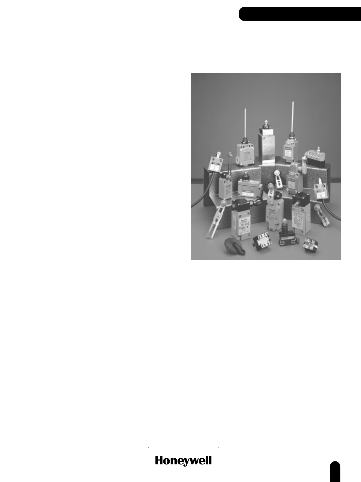
Industrial Electromechanical
Limit Switches
Honeywell offers an advanced line of heavy duty limit switches and a wide
selection of application-proven enclosed switches (precision snap-acting
switches sealed in rugged metal housing). Sealed versions keep out moisture
and other contaminants. Our products meet or exceed critical standards
allowing for global use. Our rugged switches are suitable for use in harshduty, wash-down environments. We offer a variety of circuitry, terminations
and actuators to ensure that can match your choice of switch to your
application.
Limit and enclosed switches are the cost effective switches of choice for
detecting objects which can be touched. When an object comes in contact
with an actuator, the switch operates. Rugged and dependable, these
switches are offered in a variety of sizes, with different seals, enclosures,
actuation, circuitries and electrical ratings. Enclosed switches are known for
high precision and low cost. Limit Switches are especially rugged and well
sealed. Explosion proof switches are designed for use in hazardous locations.
The Honeywell switches featured here are all proven in a broad range of
Industrial applications - machine tools, packaging machinery, lifting gear,
presses and construction machinery.
More information about our complete product range - and the depth of
product available within each product line - can be found on our interactive
catalogue at www.honeywell.com/sensing.
LIMIT SWITCHES
MICRO SWITCH Brand products
Honeywell has been at the forefront of switching technology since we were the
first to develop the precision snap-action switch more than 60 years ago.
Ever since we introduced the MICRO SWITCH Brand Products in 1937, we
have been recognized as the performance standard that all other switches are
measured against. We continue in that tradition by constantly improving the
technology, cost-effectiveness, and delivery of these hardworking, versatile
electromechanical switches.
www.honeywell.com/sensing
5
Page 8

LIMIT SWITCHES
Proper application of limit switches
The following are guidelines for the correct application of Limit Switches.
Never use the Limit Switch as a physical end stop. Mechanical damage or
incorrect operation may occur if this is done. Always ensure that the
mechanical actuator is protected from excessive mechanical shock. Never
release the actuator suddenly - gradual actuation and release will ensure that
stress on the mechanics of the switch is kept to a minimum. This has the
added benefit that the switch life will be improved. The diagrams illustrate how
to actuate your limit switch for optimum performance.
WRONG WRONG
RIGHT FIXED STOP
RIGHT
Standards and Electrical rating
IEC/EN 60947-1 explains the general rules relating to Low Voltage switchgear
and controlgear. The purpose of this standard is to harmonize as much as
possible the product performance and test requirements for equipment where
the rated voltage does not exceed 1,000 Vac or 1,500 Vdc.
IEC 60947-5-1 is part 5 of the general rules which relates to Control-circuit
devices and switching elements, where rated voltage does not exceed 1,000
Vac or 600 Vdc. There are special requirements for control switches with
positive opening operation. These switches are marked on the outside with
this symbol:
The Contact Element form defines the configuration and number of contacts
within the switch.
Form Za – both contact elements have the same polarity
Form Zb – the two contact elements are electrically separated.
The Utilization Category defines the type of current carried – ac or dc – and
the typical application where the switch is used.
The contact rating Designation relates to the Utilization Categories and defines
the conventional thermal current Ith (a) rated operational current Ie (A) at
rated operational voltages Ue and the VA rating.
Actuators
A range of actuators is available for limit switches. Illustrations of actuator
types available from this catalogue are shown at the beginning of each
product family. Other actuators may be available - for more information
please contact your local Honeywell office.
Roller lever
Top roller
lever
Adjustable
roller lever
Top pin
plunger
Top pin
plunger,
boot seal
For limit switches with pushrod actuators, the actuating force should be applied as
nearly as possible in line with the pushrod axis.
WRONG WRONG
over-riding
cam
RIGHT RIGHT
over-riding
cam
Cam or dog arrangements should be such that the actuator is not suddently released
to snap back freely.
free position
interference
WRONG WRONG
free position
end of
overtravel
operated
position
end of
overtravel
RIGHT RIGHT
Operating mechanisms for limit switches shoud be so designed that, under any
operating or emergency conditions, the limit switch is not operated beyond its
overtravel limit position. A limit switch should not be used as a mechanical stop.
Top roller
plunger
Side
pin plunger
6
Top roller
plunger,
boot seal
Side
roller plunger
Top roller
plunger,
perpendicular
Roller lever
Top roller
plunger,
perpendicular,
boot seal
Yoke lever
WRONG
Ball bearing
plunger
RIGHT
Rod lever
Wobble head
For limit switches with lever actuators, the actuating force should be applied as
nearly perpendicular to the lever as practical and perpendicular to the shaft axis
about which the lever rotates.
www.honeywell.com/sensing
non-over-riding
over-riding
Page 9

A Note on Degrees of Protection
IP Classification
The IEC 529 standard describes a system for classifying the degree of
protection provided by the enclosures of electrical equipment. The level of
protection given by the enclosure is indicated by the IP code. This code
system uses the letters ‘‘IP’’ (International Protection) followed by up to four
digits. Normally only the first two digits are used.
IP 1st Digit 2nd Digit 3rd Digit 4th Digit
The first digit is numerical and indicates the level of protection within the
enclosure against the ingress of solid foreign objects and access to hazardous
parts by persons.
The second digit is also numerical and indicates the level of protection
against the ingress of WATER into the enclosure.
The third digit is a letter and indicates a higher level of protection for persons
against access to hazardous parts.
The fourth digit is also a letter and is used in exceptional cases for
supplementary information.
If the first or second digit is not required to be specified, then it is replaced by
the letter ‘‘X’’ (‘‘XX’’ if both digits are not required). While the tables below
serve as a guide to the level of protection, Honeywell recommends that
customers refer to the full official IEC specification for the exact definitions. If
in doubt about the degree of protection required for a particular application,
please consult your local Honeywell office.
Note:
The IEC 529 standard does not relate to protection against rust, corrosion,
icing or corrosive solvents (e.g. cutting fluids) and that product coded IP 67
may not necessarily meet IP 66 requirements.
First Digit Protection against ingress of solid objects
IP TEST
0 no protection
1 protected against solid objects with a diameter greater than 50 mm
2 protected against solid objects with a diameter greater than 12 mm
3 protected against solid objects with a diameter greater than 2.5 mm
4 protected against solid objects with a diameter greater than 1 mm
5 protected against dust-limited ingress (no harmful deposit)
6 totally protected against dust
Second Digit Protection against ingress of water
IP TEST
0 no protection
1 protected against vertically falling drops of water
2 protected against vertically falling drops of water when the enclosure is tilted
at an angle up to 15 degrees
3 protected against water sprayed at an angle of 60 degrees from the vertical
4 protected against splashing water from all directions – limited ingress (no
harmful effects)
5 protected against low pressure jets of water from all directions – limited
ingress permitted
6 protected against powerful jets of water from all directions – limited ingress
permitted
7 protected against the effects of temporary immersion in water
8 protected against the effects of continuous immersion in water
LIMIT SWITCHES
NEMA Classification (USA)
NEMA (National Electrical Manufacturer’s Association) prepares standards
which define a product, process or procedure with reference to one or more of
the following: nomenclature, composition, construction, dimensions,
tolerances, safety, operating characteristics, performance, quality, electrical
rating, testing and the service for which designed. This standard provides
degrees of protection for Enclosures for Electrical Equipment (1000 Volts
Maximum) similar to that of the IEC 529 standard. The reference standard
herein reflects the latest data in the NEMA Standards Publication when this
information went to print. Please check for the latest information.
Non-hazardous locations
Type 1 enclosures are intended for indoor use primarily to provide a degree of
protection against contact with the enclosed equipment.
Type 3 enclosures are intended for outdoor use primarily to provide a degree
of protection against windblown dust, rain, sleet, and external ice formation.
Type 4 enclosures are intended for indoor or outdoor use primarily to provide
a degree of protection against windblown dust and rain, splashing water, and
hose-directed water.
Type 4X enclosures are intended for indoor or outdoor use primarily to
provide a degree of protection against corrosion, windblown dust and rain,
splashing water, and hose-directed water.
Type 6 enclosures are intended for indoor or outdoor use primarily to provide
a degree of protection against the entry of water during occasional temporary
submersion at a limited depth.
Type 6P enclosures are intended for indoor or outdoor use primarily to
provide a degree of protection against the entry of water during prolonged
submersion at a limited depth.
Type 12 enclosures are intended for indoor use primarily to provide a degree
of protection against dust, falling dirt, and dripping noncorrosive liquids.
Type 13 enclosures are intended for indoor use primarily to provide a degree
of protection against dust, spraying water, oil and noncorrosive coolant.
Note:
Enclosures are based, in general, on the broad definitions outlined in NEMA
Standards. Therefore, it will be necessary to ascertain that a particular
enclosure will be adequate when exposed to the specific conditions that might
exist in intended applications.
Except as might otherwise be noted, all references to products relative to
NEMA enclosure type are based on Honeywell evaluation and Underwriter’s
Laboratory (UL) tested. This NEMA Standards Publication does test for
environmental conditions such as corrosion, rust, icing, oil, and coolants. The
IEC 529 does not, and does not specify degree of protection against
mechanical damage of equipment. For this reason, and because the tests and
evaluations for other characteristics are not identical, the IEC Enclosure
Classification Designations cannot be exactly equated with NEMA Enclosure
Type Numbers.
www.honeywell.com/sensing
7
Page 10
GLOBAL LIMIT SWITCHES
Zb
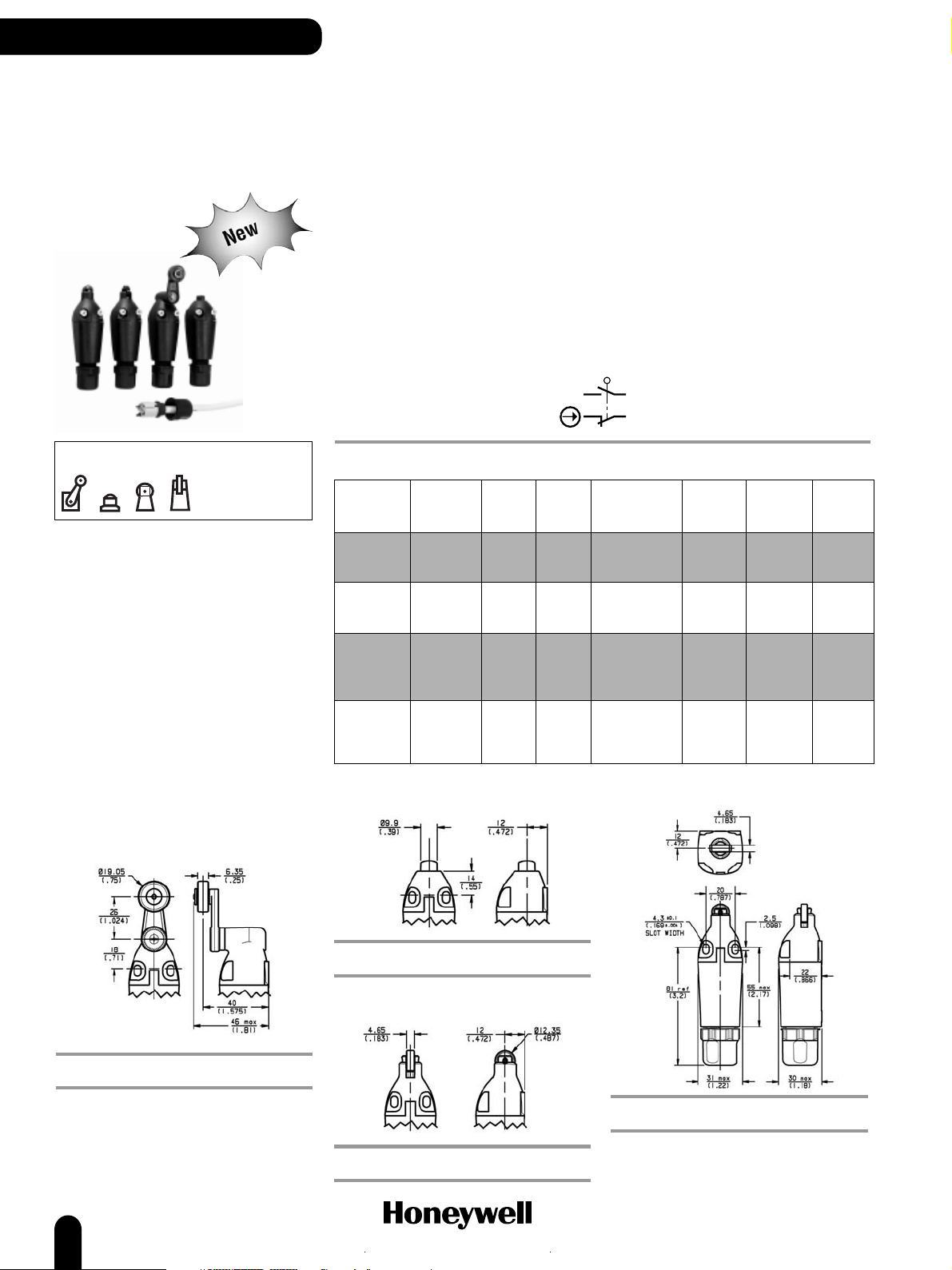
EVN2000 Series
EN 50047
Global Limit
Switches
The EVN2000 series limit switch is an innovative product which has been developed to address a need
highlighted by Original Equipment Manufacturers (OEM), where “Ease of Wiring” is required. With the
new design there is no need for access to the inside of the housing and therefore the housing cover,
cover screws and gasket become obsolete. Furthermore, the integrated cable gland eliminates the need
for additional conduit or cable gland hardware. All Normally Closed (NC) contacts are Direct Opening.
Mechanical life: 10 million
Sealing: IP 66/67, NEMA 1, 12, 13
Operating temperature: -25 °C to 85 °C (-13 °F to 185 °F)
Approvals: IEC/EN 60947-5-1
EN 60529
EN81-1
AC15 A300
DC13 Q300
UL, CE
Housing material: Plastic
Termination: Insulation Displacement Terminals (IDT)
Switching options: SPDT Single Pole, Double Throw,
Snap action contacts (1NC/1NO)
Actuators
OPTIONS
Side rotary plastic roller
Operating characteristics
Actuator Operating Free Pretravel Travel to Overtravel Differential Operating
type torque/force position positive opening travel point
Side
rotary 0,120 N m 0° 25° 45° 45° 12° 25°
A (1.10 lb in)
Top pin
plunger 16,0 N 20,0 mm 2,0 mm 3,5 mm 4,0 mm 1,0 mm 18,0 mm
B (3.60 lb) (0.79 in) (0.08 in) (0.14 in) (0.16 in) (0.04 in) (0.71 in)
Top roller
plunger, 16,0 N 30,0 mm 2,0 mm 3,5 mm 4,0 mm 1,0 mm 28,0 mm
parallel (3.60 lb) (1.18 in) (0.08 in) (0.14 in) (0.16 in) (0.04 in) (1.10 in)
C
Top roller
plunger, 16,0 N 30,0 mm 2,0 mm 3,5 mm 4,0 mm 1,0 mm 28,0 mm
perpendicular (3.60 lb) (1.18 in) (0.08 in) (0.14 in) (0.16 in) (0.04 in) (1.10 in)
D
Top pin plunger
(OF) (FP) (PT) (PO) (OT) (DT) (OP)
Top roller plunger, parallel
REFERENCE
EVN2000B
Top roller plunger, perpendicular
REFERENCE
EVN2000A
REFERENCE
EVN2000C
REFERENCE
EVN2000D
8
www.honeywell.com/sensing
Page 11

VL Series
General Purpose Compact
Limit Switches
GLOBAL LIMIT SWITCHES
The new economical SZL-VL Series miniature type limit switches are specially
designed for applications of small mounting space. These miniature switches
are ideal for OEM machinery which requires a rugged and reliable limit switch
that is capable of being mounted in space restricted applications. A wide range
of actuators and optional neon lamp indicators add additional flexibility. A
special pre-molded flexible cable gland allows for fast and simple wiring
termination.
Mechanical life: up to 10 million operations
Sealing: IP 64
Operating temperature: -20 °C to 60 °C (-4 °F to 140 °F)
Approvals: UL, C-UL, CE
Termination: Cable gland
Contacts: Gold plated silver
Electrical ratings: 250 Vac 125 Vdc max.
Ampere rating: 5 A @ 250 Vac max./0.4 A @ 125 Vdc max.
Switching options:
SPDT Single Pole, Double Throw, Double break
(1NC/1NO)
Actuators
Side rotary actuated switches
Pretravel max. (PT): 20°
Overtravel min. (OT): 75°
Differential travel max. (DT): 10°
OPTIONS
Roller lever
41.2±.08
holes)
1.622±.031
36.2±0.8
1.425±.031
20.4±0.3
.803±.012
38.1
1.5
15.1
.594
10.2
.402
18.5
.728
64
2.520
14
.551
7.5±0.2
.295±.008
25
.984
(Standard type)
2-M5 (P=0.8)
tapped
7 .276 in depth
mounting holes
2-M5 (P=0.8)
tapped
mounting holes
M4 arm fixing nut
+0.2
2-4.1
dia.
-0
mounting holes
+0.008
.161
-0
mounting holes
cover screw
M3x6
2-M3x23
cover screw
dia.
P
T
m
˚
0
2
21±0.2
.827±.008
a
1.102
x
28
18 dia.x7
nylon roller
(Roller can be
rotated and locked
in any position
through 360˚)
0
3
M4 arm
R
fixing screw
(with hexagonal
12.5
.492
56±0.3
2.205±.012
34
NO
NC
Roller lever, adjustable
Adjustable length
of arm
(30-70)
+0.2
2-4.1
dia.
0
mounting holes
+0.008
.161
dia.
-0
mounting holes
M3x6
cover screw
2-M3x23
cover screw
T
P
.827±.008
0
2
21±0.2
1.102
m
˚
28
18 dia.x7 nylon rooler
(Roller can be rotated
x
a
and locked in any
position through 360˚)
M4 arm fastening
plate screw with
hexagonal holes
Arm fasteni ng plate
56±0.3
2.205±.012
12.5
.492
Mounting metal
M6 arm fastening
plate screw with
hexagonal holes
VL
47.7±0.8
1.878±.031
1.319±.031
2.0
.079
(46.4)
33.5±0.8
28.5±0.8
1.122±.031
25
.984
(1.827)
21
10.2
.402
15.1
.594
NO
NC
42.7±0.8
1.681±.031
64
2.520
7.5±0.2
.295±.008
20.4±0.3
.803±.012
(Standard type)
18.5
.728
2-M5 (P=0.8) tapp ed
7 .276 in depth
mounting holes
2-M5 (P=0.8) tapp ed
mounting holes
14
.551
Operating torque max.: 5,88 N (1.32 lb)
REFERENCE
SZL-VL-A
www.honeywell.com/sensing
Operating torque max.: 3,35 N to 7,84 N (0.75 lb to 1.76 lb)
REFERENCE
SZL-VL-B
9
Page 12
GLOBAL LIMIT SWITCHES
VL Series
Side rotary actuated switches (continued)
Plunger actuated switches
Adjustable rod
5.5
.217
2.6 .102 dia. rod
x
a
m
˚
0
2
T
P
Adjustable lenght of rod
+0.2
dia.
2-4.1
0
mounting holes
+0.008
.161
-0
mounting holes
M3x6
cover screw
2-M3x23
cover screw
(30-118)
dia.
and locked in any
(Roller can be rotated
position through 360˚)
M4 rod fastening plate
screw with hexagonal holes
21±0.2
.827±.008
28
1.102
Rod fastening plate
Rod mounting metal
12.5
.492
M6 mounting rod
fastening screw with
hexagonal holes
56±0.3
2.205±.012
Operating torque max.: 2 N to 7,84 N
44.9
1.768
36.3±0.8
1.429±.031
(44.9)
(1.768)
REFERENCE
SZL-VL-C
10.2
.402
2.520
7.5±0.2
15.1
.295±.008
20.4±0.3
.594
.803±.012
25
.984
(0.45 lb to 1.76 lb)
18.5
.728
2-M5 (P=0.8) tapped
7 .276 in dept h
mounting holes
64
2-M5 (P=0.8) tapped
mounting holes
14
.551
(Standard type)
Pretravel max. (PT): 1,5 mm (0.060 in)
Overtravel min. (OT): 4,0 mm (0.158 in)
Differential travel max. (DT): 0,7 mm (0.028 in)
Operating force max. (OF): 8,83 N (2 lb)
Top pin plunger
7. 276 dia.
stainless steel plunger
+0.2
dia.
2-4.1
0
mounting holes
+0.008
.161
-0
mounting holes
M3x6
cover screw
2-M3x23
cover screw
PT 1.5 max
dia.
21±0.2
.827±.008
28
1.102
3
.118
26.5
1.043
56±0.3
2.205±.012
10.2
402
.
20.4±0.3
.803±.012
15.1
.594
25
.984
4
.157
64
2.520
14
.551
7.5±0.2
.295±.008
(Standard type)
2-M5 (P=0.8) tapped
7 .276 in depth
mounting holes
2-M5 (P=0.8) tapped
mounting holes
Top roller plunger
12.5 dia.x3.8
stainless steel roller
PT 1.5 max
+0.2
2-4.1
dia.
0
mounting holes
+0.008
.161
dia.
-0
mounting hole s
M3x6
cover screw
2-M3x23
cover screw
21±0.2
.827±.008
28
1.102
14.8
.583
38
1.496
56±0.3
2.205±.012
REFERENCE
SZL-VL-D
10.2
.402
20.4±0.3
.803±.012
15.1
.594
25
.984
REFERENCE
SZL-VL-H
4
.157
64
2.520
14
.551
7.5±0.2
.295±.008
(Standard type)
2-M5 (P=0.8) tapped
7 .276 in depth
mounting hole s
2-M5 (P=0.8) tapped
mounting holes
10
www.honeywell.com/sensing
Page 13
GLOBAL LIMIT SWITCHES
Plunger actuated switches (continued)
Cross roller plunger
12.5 dia.x3.8
stainless steel roller
PT 1.5 max
+0.2
2-4.1
dia.
0
mounting holes
+0.008
.161
dia.
-0
mounting holes
M3x6
cover screw
2-M3x23
cover screw
21±0.2
.827±.008
28
1.102
14.8
.583
56±0.3
2.205±.012
38
1.496
20.4±0.3
.803±.012
15.1
.594
25
.984
REFERENCE
SZL-VL-E
10.2
.402
4
.157
64
2.520
14
.551
7.5±0.2
.295±.008
(Standard type)
2-M5 (P=0.8) tapped
7 .276 in depth
mounting holes
2-M5 (P=0.8) tapped
mounting holes
Wobble actuated switches
Pretravel max. (PT): 30 mm (1.18 in)
Overtravel min. (OT): 20 mm (0.788 in)
Operating force max. (OF): 0,88 N (0.2 lb)
Plastic rod, coil spring
10.2
3 dia.
.118
5.8 dia.
.228
.402
20.4±0.3
.803±.012
15.1
.594
25
.984
4
.157
2-M5 (P=0.8) tapped
7 .276 in depth
mounting holes
64
2.520
2-M5 (P=0.8) tapped
mounting holes
14
.551
7.5±0.2
.295±.008
(Standard type)
+0.2
dia.
2-4.1
0
mounting holes
+0.008
.161
dia.
-0
mounting holes
M3x6
cover screw
2-M3x23
cover screw
PT 50 max
21±0.2
.827±.008
28
1.102
41.5
1.634
100±1.5
3.937±.059
56±0.3
2.205±.012
Nylon rod
Coil spring
SZL-VL-G
2-4.1
mounting holes
.161
mounting holes
2-M3x23
cover screw
+0.2
dia.
0
+0.008
dia.
-0
M3x6
cover screw
PT 30 max
21±0.2
.827±.008
28
1.102
51.5
2.028
100±1.5
3.937±.059
56±0.3
2.205±.012
REFERENCE
SZL-VL-F
1.2 dia.
.047 stainless
steel wire
10.2
.402
20.4±0.3
.803±.012
15.1
.594
25
.984
4
.157
2-M5 (P=0
7 .276 in depth
mounting holes
64
2.520
2-M5 (P=0.8)
mounting holes
14
.551
7.5±0.2
.295±.008
(Standard type)
.8) tapped
tapped
www.honeywell.com/sensing
REFERENCE
SZL-VL-G
11
Page 14
GLOBAL LIMIT SWITCHES
GLS Series
Global Limit
Switches
Electrical ratings
IEC947-5-1/EN60947-5-1
Designation & Rated operational current Ie (A) VA
Utilization Category at rated operational voltage Ue rating
120V 240V 380V 480V 500V 600V Make Break
AC15 A600 6 3 1.9 1.5 1.4 1.2 7200 720
AC15 A300 6 3 - - - - 7200 720
AC15 B300 3 1.5 - - - - 3600 360
AC14 D300 0.6 0.3 - - - - 432 72
125V 250V
DC13 Q300 0.55 0.27 69 69
DC13 R300 0.22 0.1 28 28
GLS Series switches offer a complete range of CENELEC approved products,
and are suitable for most industrial applications.
The standard product EN 50041 norm defines the switch mounting centres as
30 mm x 60 mm and also defines the switching characteristics of the side
rotary head with fixed lever, top pin plunger and top roller plunger. This means
that the switch can be interchanged in the application with other EN 50041
switches with mounting and switching characteristics maintained. Honeywell
offers many more head styles and switching options.
The miniature EN 50047 product range offers the user a choice of plastic,
metal and three conduit versions which are all mounting (20 mm x 22 mm)
compatible with each other. The EN 50047 standard defines how the switches
are mounted and the switching characteristics for fixed side rotary lever, top
pin plunger and top roller plunger.
Switching options:
SPDT Single Pole, Double Throw, Snap action contacts (1NC/1NO)
13
14
22
21
DPDT Double Pole, Double Throw Snap action contacts (2NC/2NO)
13
11
23
21
14
12
24
22
Operating characteristics
Actuator
type
Lever types
A,
A*A, A*B,
A4J
Top pin
plunger
B
Top roller
plunger
C
Top roller
lever
D
Wobble head
E7B, E7D,
K8B, K8C
Body
size
EN50041
(GLA)
EN50047
(GLC, GLD,
GLE)
EN50041
(GLA)
EN50047
(GLC, GLD,
GLE)
EN50041
(GLA)
EN50047
(GLC, GLD,
GLE)
EN50041
(GLA)
EN50047
(GLC, GLD,
GLE)
EN50041
(GLA)
EN50047
(GLC, GLD,
GLE)
Operating torque/force
SPDT DPDT SPDT DPDT SPDT DPDT SPDT DPDT SPDT DPDT SPDT DPDT SPDT DPDT
0,120 N m
(1.10 lb in)
16,0 N
(3.60 lb)
16,0 N
(3.60 lb)
11,0 N
(2.4 lb)
1,3 N
(0.29 lb)
(OF)
0,330 N m
(2.90 lb in)
0,165 N m
(1.50 lb in)
GLE only
16,0 N
(3.60 lb)
(2.90 lb)
GLE only
16,0 N
3.60 lb
(2.90 lb)
GLE only
9,5 N
(2.10 lb)
GLE only
0,1 N
(0.90 in lb)
(0.25 lb)
GLE only
13,0 N
13,0 N
9,0 N
(1.9 lb)
1,1 N
Free position
(FP)
0˚ 55˚26˚
37,5 mm
(1.48 in)
21,0 mm
(0.83 in)
50,5 mm
(2.00 in)
31,0 mm
(1.22 in)
65,2 mm
(2.57 in)
39,25 mm
(1.55 in)
0˚
Pretravel
(PT)
2,5 mm
(0.10 in)
3,0 mm
(0.12 in)
2,5 mm
(0.10 in)
3,0 mm
(0.12 in)
4,2 mm
(0.165 in)
3,45 mm
(0.14 in)
18˚
16˚
Actuators
Travel to
positive opening
(PO)
4,5 mm
(0.18 in)
5,0 mm
(0.20 in)
4,5 mm
(0.18 in)
5,0 mm
(0.20 in)
8,3 mm
(0.33 in)
6,9 mm
(0.27 in)
__
__
Overtravel
(OT)
59˚
49˚
4,5 mm
(0.18 in)
3,0 mm
(0.12 in)
4,5 mm
(0.18 in)
3,0 mm
(0.12 in)
9,0 mm
(0.35 in)
5,2 mm
(0.205 in)
__
__
Differential travel
(DT)
12˚
11.5˚ 8˚
0,9 mm
(0.035 in)
0,9 mm
(0.035 in)
0,9 mm
(0.035 in)
0,6 mm
(0.024 in)
0,9 mm
(0.035 in)
0,6 mm
(0.024 in)
1,7 mm
(0.067 in
1,3 mm
(0.19 in)
8˚
10˚ 7˚
Operating point
(OP)
26˚
35,0 mm
(1.38 in)
18,0 mm
(0.71 in)
48,0 mm
(1.89 in)
28,0 mm
(1.10 in)
61,0 mm
(2.40 in)
35,8 mm
(1.41 in)
__
__
12
www.honeywell.com/sensing
Page 15
GLA EN 50041
Standard metal body
GLOBAL LIMIT SWITCHES
Mechanical life: up to 15 million
Sealing: IP 67, NEMA 1, 4, 12, 13
Operating temperature: -25 °C to 85 °C
(-13 °F to 185 °F)
Approvals: IEC/EN 60947-5-1
AC15 A300/A600
DC13 Q300
UL, CSA, CE
Switching options:
SPDT Single Pole, Double Throw
Snap action contacts (1NC/1NO)
DPDT Double Pole, Double Throw
Snap action contacts (2NC/2NO)
HEAD OPTIONS
Side rotary
Side rotary adjustable roller
Plastic roller
CONTACT CONDUIT REFERENCE
SPDT ½ in NPT GLAA01A2A
DPDT ½ in NPT GLAA20A2A
SPDT PG 13,5 GLAB01A2A
DPDT PG 13,5 GLAB20A2A
SPDT 20 mm GLAC01A2A
Metal roller
CONTACT CONDUIT REFERENCE
SPDT ½ in NPT GLAA01A2B
DPDT ½ in NPT GLAA20A2B
SPDT PG 13,5 GLAB01A2B
DPDT PG 13,5 GLAB20A2B
SPDT 20 mm GLAC01A2B
DPDT 20 mm GLAC20A2B
Side rotary adjustable metal rod
41
(1.61)
Top pin plunger
37,5
FP
(1.48)
CONTACT CONDUIT REFERENCE
SPDT ½ in NPT GLAA01B
DPDT ½ in NPT GLAA20B
SPDT PG 13,5 GLAB01B
DPDT PG 13,5 GLAB20B
SPDT 20 mm GLAC01B
DPDT 20 mm GLAC20B
Top roller plunger
FP
CONTACT CONDUIT REFERENCE
SPDT ½ in NPT GLAA01C
DPDT ½ in NPT GLAA20C
SPDT PG 13,5 GLAB01C
DPDT PG 13,5 GLAB20C
SPDT 20 mm GLAC01C
DPDT 20 mm GLAC20C
No lever
Levers: Levers for side rotary types are ordered
separately (see pages 69-71 for details)
CONTACT CONDUIT REFERENCE
SPDT ½ in NPT GLAA01A
DPDT ½ in NPT GLAA20A
SPDT PG 13,5 GLAB01A
Plastic roller
CONTACT CONDUIT REFERENCE
SPDT ½ in NPT GLAA01A1A
DPDT ½ in NPT GLAA20A1A
SPDT PG 13,5 GLAB01A1A
DPDT PG 13,5 GLAB20A1A
SPDT 20 mm GLAC01A1A
DPDT 20 mm GLAC20A1A
Metal roller
CONTACT CONDUIT REFERENCE
SPDT ½ in NPT GLAA01A1B
DPDT ½ in NPT GLAA20A1B
SPDT PG 13,5 GLAB01A1B
DPDT PG 13,5 GLAB20A1B
SPDT 20 mm GLAC01A1B
DPDT 20 mm GLAC20A1B
¯ 3,2
4,5
34
(1.34)
CONTACT CONDUIT REFERENCE
SPDT ½ in NPT GLAA01A4J
DPDT ½ in NPT GLAA20A4J
SPDT PG 13,5 GLAB01A4J
DPDT PG 13,5 GLAB20A4J
SPDT 20 mm GLAC01A4J
(.17)
(.13)
75˚75˚
32 - 134
(1.26 - 5,28)
15
(.6)
Top roller lever
13,0
(.51)
65,2
FP
(2.51)
35
(1.38)
CONTACT CONDUIT REFERENCE
SPDT ½ in NPT GLAA01D
DPDT ½ in NPT GLAA20D
SPDT PG 13,5 GLAB01D
DPDT PG 13,5 GLAB20D
SPDT 20 mm GLAC01D
DPDT 20 mm GLAC20D
Ø 18,7
(.74)
www.honeywell.com/sensing
13
Page 16
GLOBAL LIMIT SWITCHES
GLA EN 50041
Standard metal body
(continued)
Wobble, coil actuator
CONTACT CONDUIT REFERENCE
SPDT ½ in NPT GLAA01E7B
SPDT PG 13,5 GLAB01E7B
DPDT PG 13,5 GLAB20E7B
SPDT 20 mm GLAC01E7B
DPDT 20 mm GLAC20E7B
Coil wobble head, stainless steel
spring actuator
Wobble, cat whisker
GLC EN 50047
Standard metal body
24,75
(0.97)
30
(1.18)
14,5
(.57)
conduit thread
PG 13,5
(.12)
R
15,25
(.600)
3
(.08)
2,15
(.87)
(.78)
30,5
(1.20)
22
20
55
(2.16)
3,5
(0.138)
CONTACT CONDUIT REFERENCE
SPDT ½ in NPT GLAA01E7D
CONTACT CONDUIT REFERENCE
SPDT ½ in NPT GLAA01K8B
SPDT PG 13,5 GLAB01K8B
Wobble, cat whisker, coil actuator
CONTACT CONDUIT REFERENCE
SPDT ½ in NPT GLAA01K8C
DPDT ½ in NPT GLAA20K8C
SPDT PG 13,5 GLAB01K8C
Mechanical life: up to 10 million
Sealing: IP 66, NEMA 1, 4, 12, 13
Operating temperature: -25 °C to 85 °C
-13 °F to 185 °F
Approvals: IEC/EN 60947-5-1
AC15 A300
DC13 Q300
UL, CSA, CE
Switching options:
SPDT Single Pole, Double Throw
Snap action contacts (1NC/1NO)
HEAD OPTIONS
Side rotary
°
Plastic roller
CONTACT CONDUIT REFERENCE
SPDT ½ in NPT GLCA01A1A
SPDT PG 13,5 GLCB01A1A
14
www.honeywell.com/sensing
Metal roller
CONTACT CONDUIT REFERENCE
SPDT ½ in NPT GLCA01A1B
SPDT PG 13,5 GLCB01A1B
SPDT 20 mm GLCC01A1B
Page 17
GLC EN 50047
Standard metal body
(continued)
GLOBAL LIMIT SWITCHES
Side rotary adjustable
Plastic roller
CONTACT CONDUIT REFERENCE
SPDT ½ in NPT GLCA01A2A
SPDT PG 13,5 GLCB01A2A
Metal roller
CONTACT CONDUIT REFERENCE
SPDT ½ in NPT GLCA01A2B
SPDT PG 13,5 GLCB01A2B
SPDT 20 mm GLCC01A2B
Side rotary adjustable, metal rod
41
(1.61)
Top pin plunger
Ø 9.9
(.390)
CONTACT CONDUIT REFERENCE
SPDT ½ in NPT GLCA01B
SPDT PG 13,5 GLCB01B
SPDT 20 mm GLCC01B
DT
OP
±0,5
18
(.709)
Top roller plunger
31,0
FP
1.22
CONTACT CONDUIT REFERENCE
SPDT ½ in NPT GLCA01C
SPDT PG 13,5 GLCB01C
SPDT 20 mm GLCC01C
Top roller lever
Wobble, coil actuator
➞
Mechanical life: up to 5 million
CONTACT CONDUIT REFERENCE
SPDT ½ in NPT GLCA01E7B
SPDT PG 13.5 GLCB01E7B
SPDT 20 mm GLCC01E7B
Wobble, cat whisker
¯ 3,2
4,5
34
(1.34)
CONTACT CONDUIT REFERENCE
SPDT ½ in NPT GLCA01A4J
SPDT PG 13,5 GLCB01A4J
(.17)
(.13)
75˚75˚
32 - 134
(1.26 - 5,28)
15
(.6)
Ø
39,2
FP
(1.54)
CONTACT CONDUIT REFERENCE
SPDT ½ in NPT GLCA01D
SPDT PG 13,5 GLCB01D
SPDT 20 mm GLCC01D
Mechanical life: 5 million
CONTACT CONDUIT REFERENCE
SPDT ½ in NPT GLCA01K8A
SPDT PG 13,5 GLCB01K8A
www.honeywell.com/sensing
15
Page 18
GLOBAL LIMIT SWITCHES
GLD EN 50047
Double insulated
standard body
22
24,75
(0.97)
3
(.12)
2,15
R
(.08)
30
(1.18)
14,5
(.57)
15,25
(.600)
conduit thread
PG 13,5
Mechanical life: See GLC section
Sealing: IP 66, NEMA 1, 2, 13
Operating temperature: -25 °C to 85 °C
Approvals: IEC/EN 60947-5-1
Switching options:
SPDT Single Pole, Double Throw
Snap action contacts (1NC/1NO)
HEAD OPTIONS
(.87)
20
(.78)
55
(2.16)
30,5
(1.20)
3,5
(0.138)
-13 °F to 185 °F
AC15 A600
DC13 Q300
UL, CSA, CE
Side rotary adjustable
Plastic roller/metal lever
CONTACT CONDUIT REFERENCE
SPDT ½ in NPT GLDA01A2A
SPDT PG 13.5 GLDB01A2A
Metal roller/metal lever
CONTACT CONDUIT REFERENCE
SPDT ½ in NPT GLDA01A2B
SPDT PG 13,5 GLDB01A2B
SPDT 20 mm GLDC01A2B
Side rotary adjustable metal rod
CONTACT CONDUIT REFERENCE
SPDT ½ in NPT GLDA01A4J
SPDT PG 13,5 GLDB01A4J
Top pin plunger
CONTACT CONDUIT REFERENCE
SPDT ½ in NPT GLDA01B
SPDT PG 13,5 GLDB01B
SPDT 20 mm GLDC01B
Top roller plunger
CONTACT CONDUIT REFERENCE
SPDT ½ in NPT GLDA01C
SPDT PG 13,5 GLDB01C
SPDT 20 mm GLDC01C
GLE EN 50047 Compatible
3 conduit
metal standard body
Mechanical life: up to 10 million
Sealing: IP 66, NEMA 1, 4, 12, 13
Operating temperature: -25 °C to 85 °C
-13 °F to 185 °F
Approvals: IEC/EN 60947-5-1
AC15 A300
DC13 Q300
UL, CSA, CE
Switching options:
SPDT Single Pole, Double Throw
Snap action contacts (1NC/1NO)
DPDT Double Pole, Double Throw
Snap action contacts (2NC/2NO)
HEAD OPTIONS
Side rotary
See GLC section for dimension
illustrations
Side rotary
Plastic roller/lever
CONTACT CONDUIT REFERENCE
SPDT ½ in NPT GLDA01A1A
SPDT PG 13,5 GLDB01A1A
Metal roller/lever
CONTACT CONDUIT REFERENCE
SPDT ½ in NPT GLDA01A1B
SPDT PG 13,5 GLDB01A1B
SPDT 20 mm GLDC01A1B
16
Top roller lever
CONTACT CONDUIT REFERENCE
SPDT ½ in NPT GLDA01D
SPDT PG 13,5 GLDB01D
SPDT 20 mm GLDC01D
Wobble, coil actuator
CONTACT CONDUIT REFERENCE
SPDT ½ in NPT GLDA01E7B
SPDT PG 13,5 GLDB01E7B
SPDT 20 mm GLDC01E7B
www.honeywell.com/sensing
Plastic roller
CONTACT CONDUIT REFERENCE
SPDT ½ in NPT GLEA01A1A
SPDT PG 13,5 GLEB01A1A
DPDT PG 13,5 GLEB24A1A
Metal roller
CONTACT CONDUIT REFERENCE
SPDT ½ in NPT GLEA01A1B
DPDT ½ in NPT GLEA24A1B
SPDT PG 13,5 GLEB01A1B
DPDT PG 13,5 GLEB24A1B
SPDT 20 mm GLEC01A1B
Page 19

GLE EN 50047 Compatible
Þ
OT
35˚ (max)
DT
10˚
16˚ ±5˚
(2.37)
OP
100
(3.92)
3 conduit
metal standard body
(continued)
GLOBAL LIMIT SWITCHES
Offset side rotary roller
Plastic roller
CONTACT CONDUIT REFERENCE
SPDT ½ in NPT GLEA01A5A
SPDT PG 13,5 GLEB01A5A
Side rotary adjustable
Side rotary adjustable metal rod
41
(1.61)
¯ 3,2
4,5
34
(1.34)
CONTACT CONDUIT REFERENCE
SPDT PG 13,5 GLEB01A4J
DPDT PG 13,5 GLEB24A4J
(.17)
(.13)
75˚75˚
32 - 134
(1.26 - 5,28)
15
(.6)
Top pin plunger
18
(0.709)
Top roller lever
39,2
FP
(1.54)
CONTACT CONDUIT REFERENCE
SPDT ½ in NPT GLEA01D
DPDT ½ in NPT GLEA24D
SPDT PG 13,5 GLEB01D
DPDT 13,5 GLEB24D
SPDT 20 mm GLEC01D
DPDT 20 mm GLEC24D
Wobble, coil actuator
Plastic roller
CONTACT CONDUIT REFERENCE
SPDT ½ in NPT GLEA01A2A
DPDT ½ in NPT GLEA24A2A
SPDT PG 13,5 GLEB01A2A
Metal roller
CONTACT CONDUIT REFERENCE
SPDT ½ in NPT GLEA01A2B
SPDT PG 13,5 GLEB01A2B
DPDT PG 13,5 GLEB24A2B
CONTACT CONDUIT REFERENCE
SPDT ½ in NPT GLEA01B
DPDT ½ in NPT GLEA24B
SPDT PG 13,5 GLEB01B
DPDT PG 13,5 GLEB24B
Top roller plunger
Ø 12,4
31,0
FP
1.23
CONTACT CONDUIT REFERENCE
SPDT ½ in NPT GLEA01C
DPDT ½ in NPT GLEA24C
SPDT PG 13,5 GLEB01C
DPDT PG 13,5 GLEB24C
DPDT 20 mm GLEC24C
(0.49)
Mechanical life: up to 5 million
CONTACT CONDUIT REFERENCE
SPDT ½ in NPT GLEA01E7B
DPDT ½ in NPT GLEA24E7B
SPDT PG 13,5 GLEB01E7B
DPDT PG 13,5 GLEB24E7B
www.honeywell.com/sensing
17
Page 20

COMPACT LIMIT SWITCHES
SL1 Series
Compact Limit
Switches
Actuators
OPTIONS
The SL1 Series compact limit switches are sealed, sensitive and have a long life. The compact size makes them suitable
for the total miniaturization of machinery or equipment.
Mechanical life: 10 million
Sealing: IP 67, NEMA 3, 4, 13
Operating temperature: -10 °C to 70 °C (14 °F to 160 °F)
Approvals: UL, CSA, CE
Termination: Cable gland
Operating force max. (OF): 11,76 N (2.64 lb)
Pretravel max. (PT): 1,5 mm (0.060 in)
Overtravel min. (OT): 3,0 mm (0.118 in)
Differential travel max. (DT): 0,10 mm (0.004 in)
Electrical rating/contact: SL1-* 5A - 125, 250 Vac Silver
SL1-* K 0.1 A - 125 Vac; 0.1 A - 30 Vdc Gold clad cross point
Switching options:
SPDT Single Pole, Double Throw,
Snap action contacts (1NC/1NO)
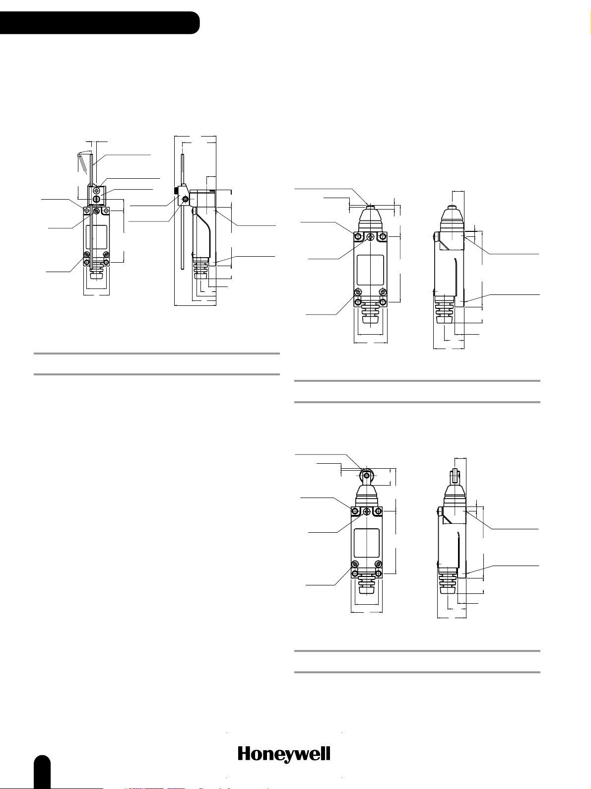
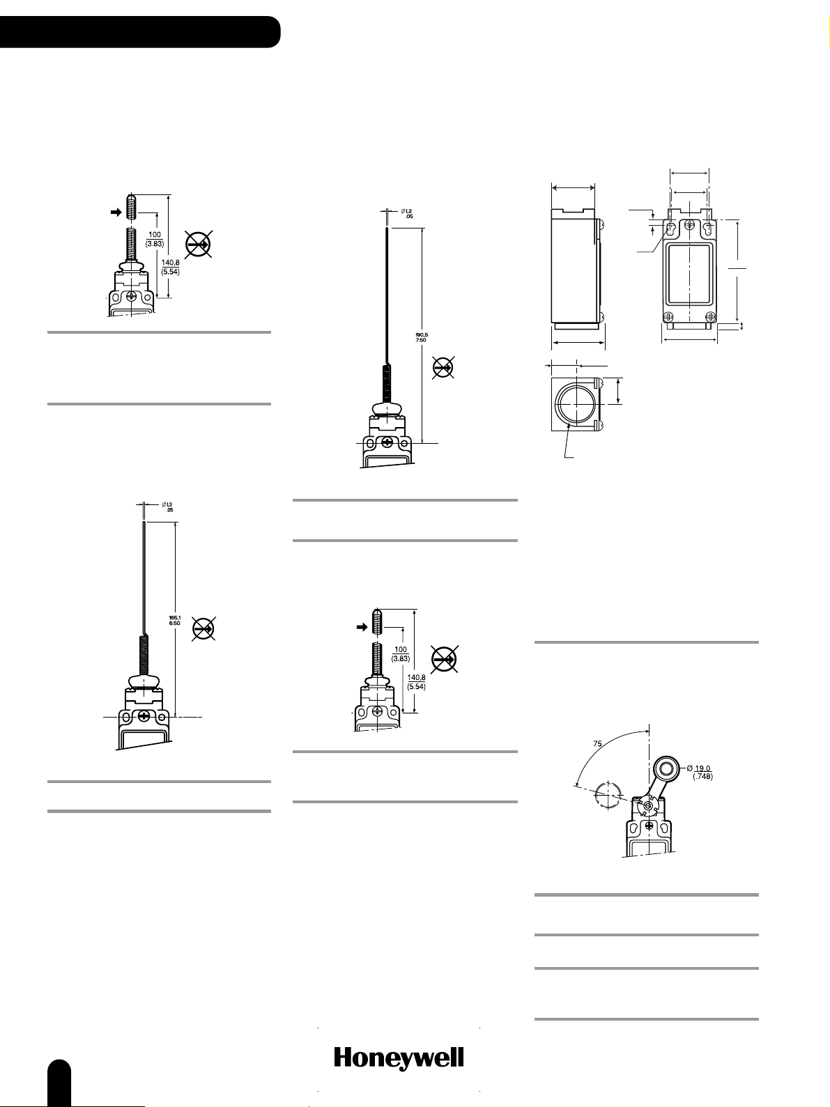
Top pin plunger
25,4
(OP)
CONTACT REFERENCE
Silver SL1-H
Gold clad cross point SL1-HK
Top roller plunger, parallel
31,4
(OP)
Top roller plunger, parallel, boot seal
PT
CONTACT REFERENCE
Silver SL1-B
Gold clad cross point SL1-BK
Top roller plunger, long, parallel
41,4
(OP)
11 D X 4W ROLLER
CONTACT REFERENCE
Silver SL1-A
Gold clad cross point SL1-AK
18
CONTACT REFERENCE
Silver SL1-E
Gold clad cross point SL1-EK
www.honeywell.com/sensing
Page 21
COMPACT LIMIT SWITCHES
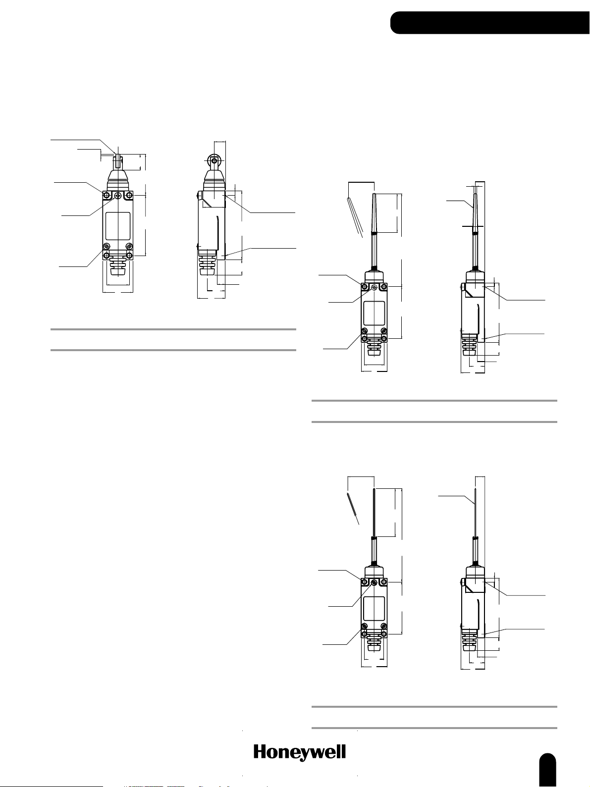
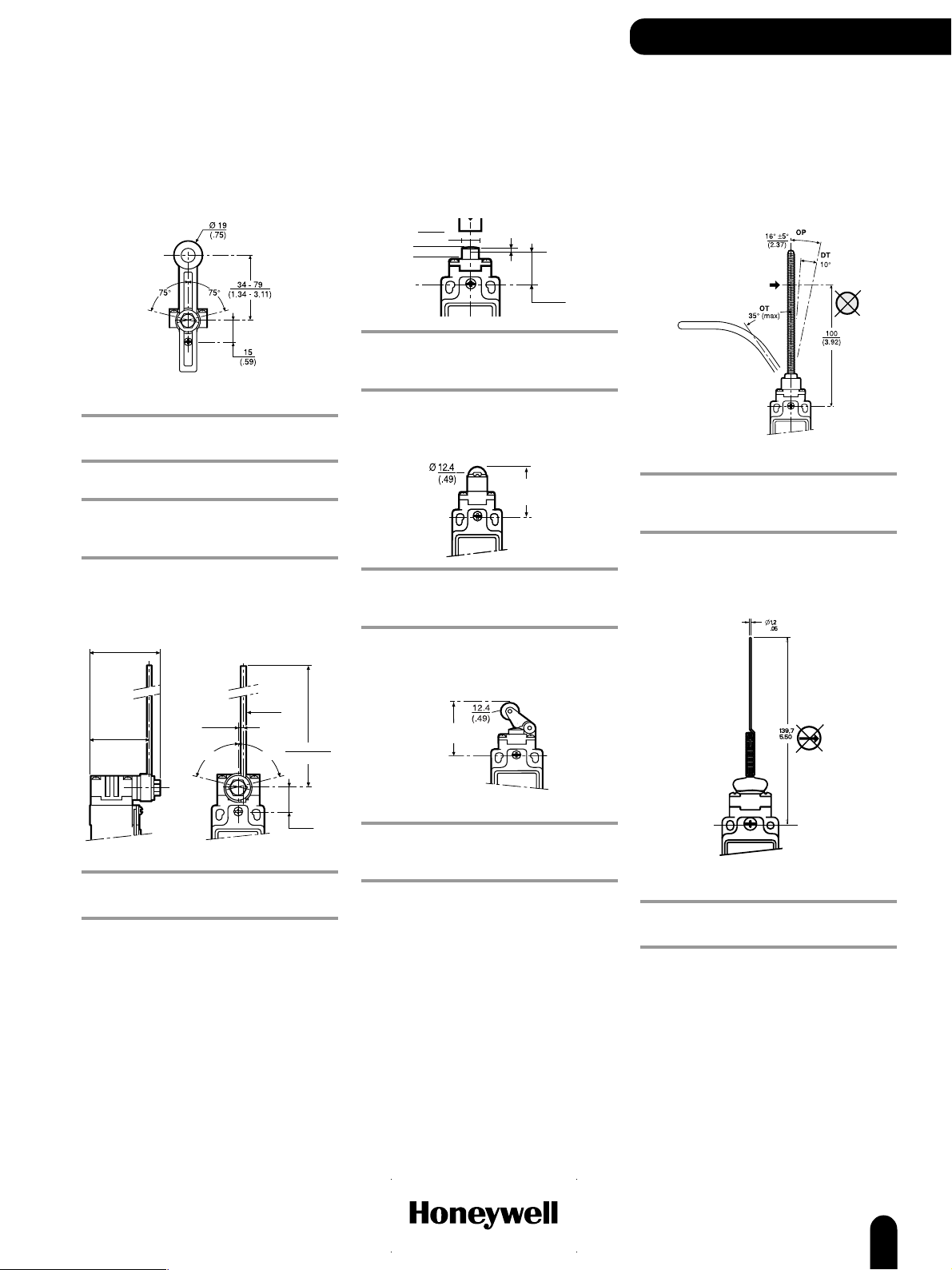
Top roller plunger, perpendicular
31,4
(OP)
CONTACT REFERENCE
Silver SL1-D
Gold clad cross point SL1-DK
Top roller plunger, long, perpendicular
Top roller lever
Operating force max. (OF): 3,92 N (0.88 lb)
Pretravel max. (PT): 2,0 mm (0.079 in)
Overtravel min. (OT): 4,0 mm (0.158 in)
Differential travel max. (DT): 0,3 mm (0.012 in)
CONTACT REFERENCE
Silver SL1-P
Gold clad cross point SL1-PK
41,4
(OP)
CONTACT REFERENCE
Silver SL1-K
Gold clad cross point SL1-KK
www.honeywell.com/sensing
19
Page 22
COMPACT LIMIT SWITCHES
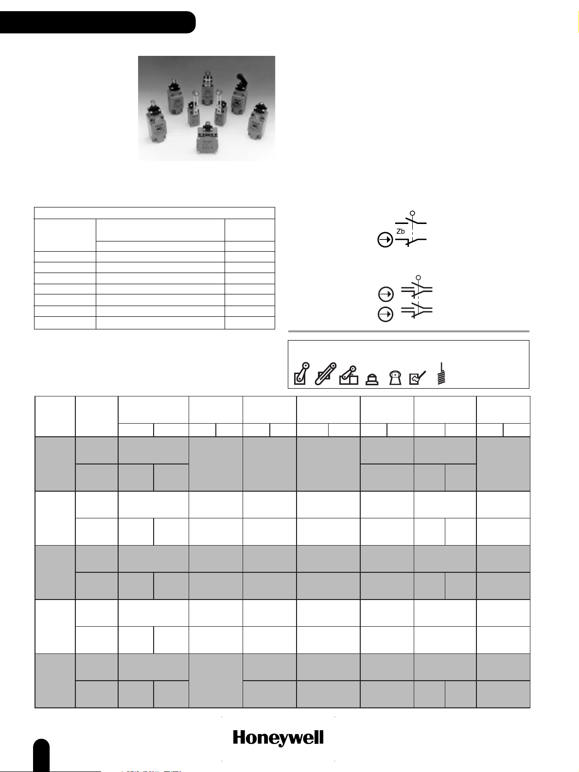
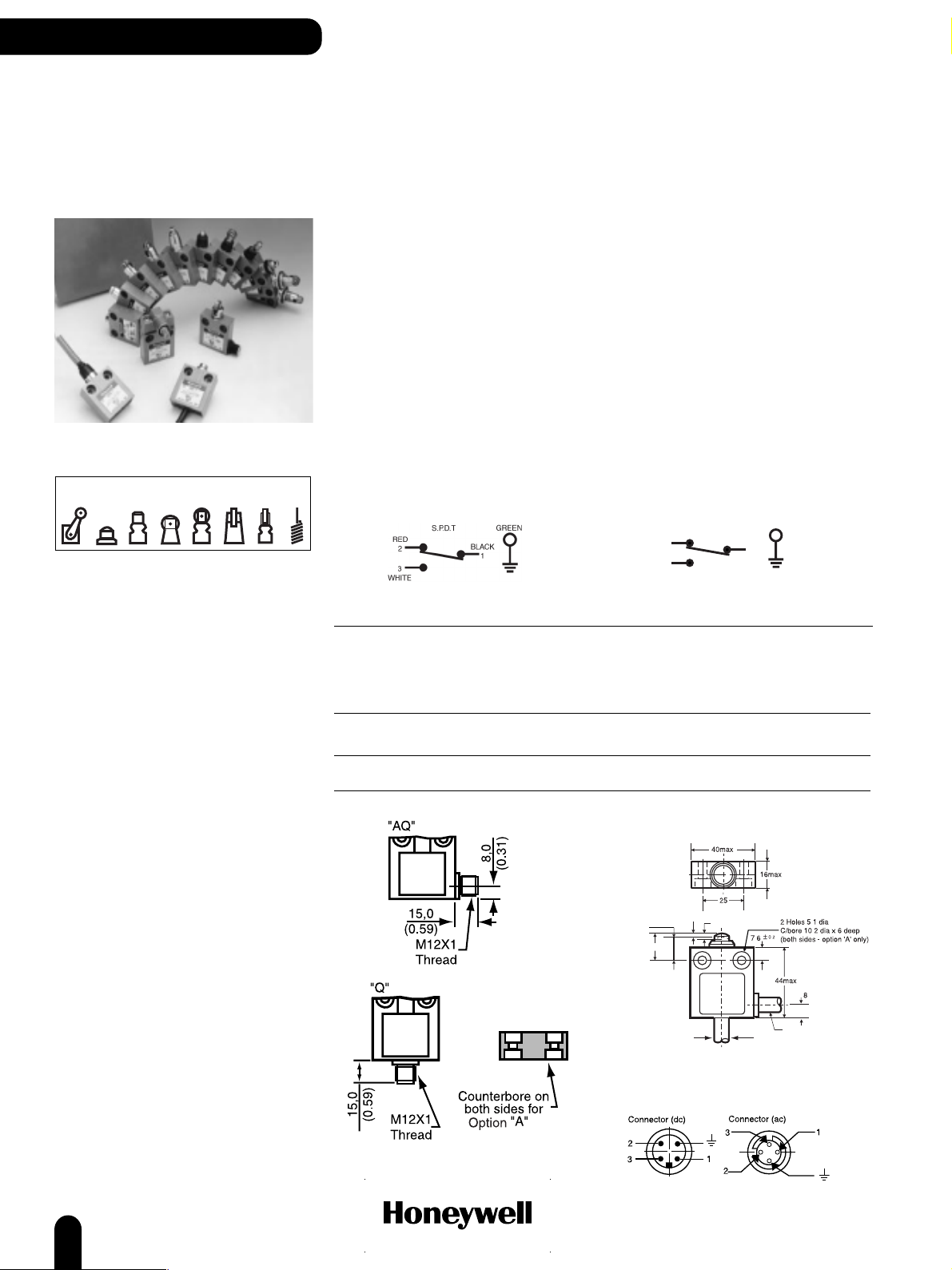
14CE/914CE Series
Miniature Enclosed
Switches
Actuators
The 14CE/914CE Series offers a miniature, rugged, compact, pre-wired switch which has proved itself
successful and gained wide market acceptance. The entire range of 14CE and 914CE switches has been
approved to meet the requirements of the Low Voltage directive and is therefore CE marked.
CE switches have different degrees of protection from IP66 to IP68 for the fully booted head styles. The
cable entry is fully potted using a special compound to ensure that ingress is virtually impossible.
Mechanical life: 10 million
Sealing: IP66, IP67, IP68
NEMA 1, 2, 3, 3R, 4, 6, 6P, 12 (boot seal), 13
Operating temperature: 14CE 0 °C to 70 °C (32 °F to 158 °F)
914CE 0 °C to 105 °C (32 °F to 221 °F)
Approvals: 14CE CE
914CE CSA, UL, CE
AC14 D300
DC13 R300
Operating force (OF): 11,8 N (2,65 lb) max.
Pretravel (PT): 1,8 mm (0.71 in) max.
Overtravel (OT): 3,0 mm (0.118 in) min.
Differential travel (DT): 0,1mm (0.004 in) max.
Contact/Rating: (9)14CE* -* Silver A
(9)14CE* -*G Gold B
(9)14CE* -Q, -AQ, -AQ1 Silver C
Connection: Harmonised CENELEC 4 x 0,75 mm2 cable (14CE)
SJTO 4 x 0,75 mm2 (18 AWG) cable (914CE)
Connector (dc), 4 pin male, M12 thread (-Q)
Connector (ac), 4 pin male, ½ in x 20 thread (-Q1)
Switching options: SPDT Single Pole, Double Throw
Snap action contacts (1NC/1NO)
GREEN/YELLOW
S.P.D.T
914CE 14CE
BROWN
2
3
BLACK
BLUE
1
Electrical ratings: Amps
Make Break
A 240 Vac, ind. 1.2 0.2
240 Vac, res. 5 5
28 Vdc, res. 3 3
28 Vdc, ind. 3 3
UL/CSA: 5 A, 1/10 Hp, 125 or 250 Vac
B 1 A res., 0.5 A ind., 30 Vdc
UL: 1 A, 125 Vac
C UL/CSA: 3 A, 125 or 250 Vac
Operating
point
Free position
914CE 8,65 (0.34)
1,8 max PT
(OP)
(FP)
Ø
14CE 7,4 (0.29)
3 min OT
,
,
,
Side exit cable
(Option 'A')
20
www.honeywell.com/sensing
Page 23
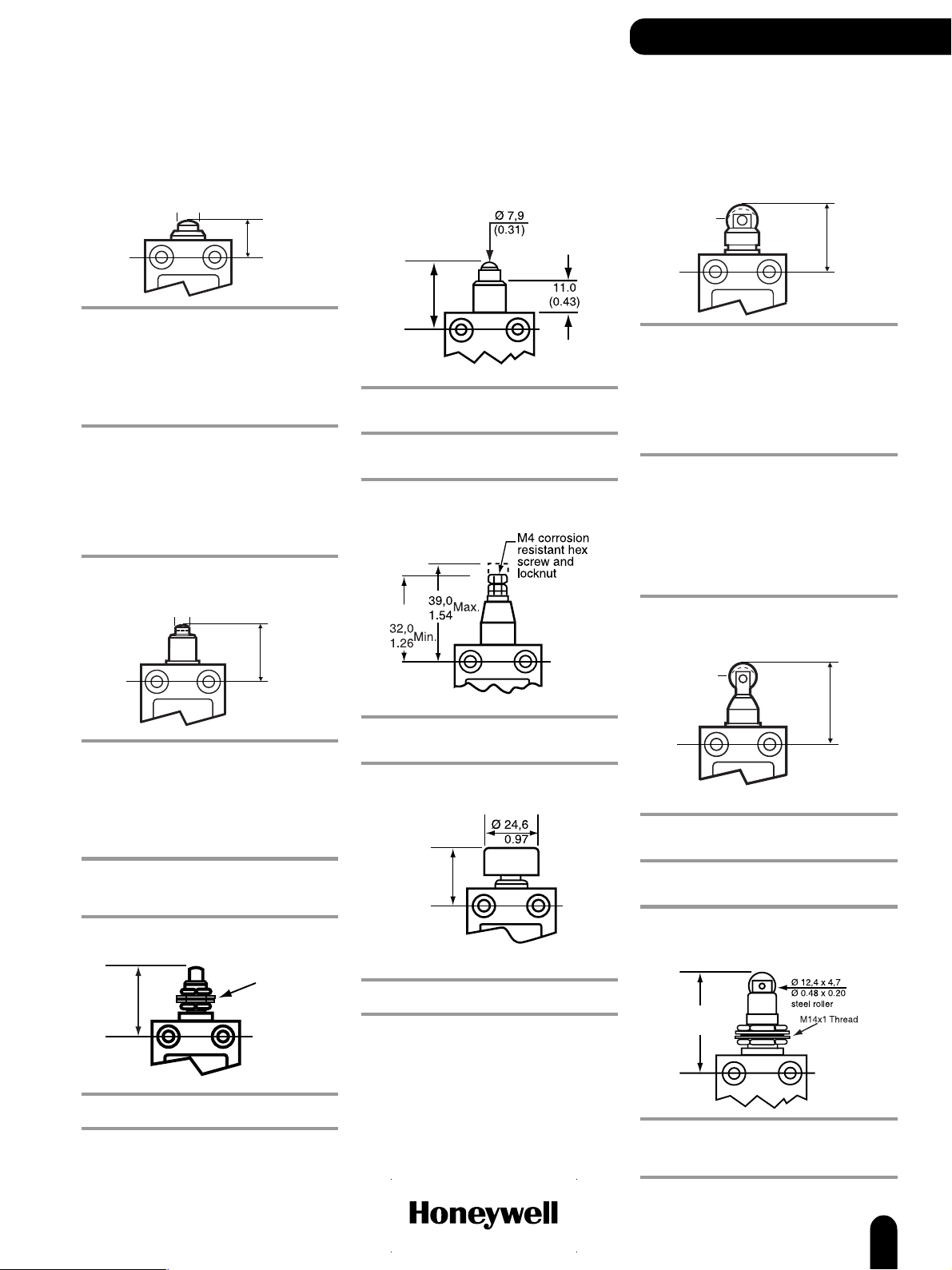
Plunger actuated switches
OPTIONS
COMPACT LIMIT SWITCHES
Top pin plunger
Ø 10,0
(0.39)
NORTH AMERICA/GLOBAL REFERENCE
3 ft cable, bottom exit 914CE1-3
3 ft cable, side exit 914CE1-3A
3 ft cable, bottom exit, gold contacts 914CE1-3G
6 ft cable, bottom exit 914CE1-6
6 ft cable, bottom exit, gold contacts 914CE1-6G
9 ft cable, bottom exit 914CE1-9
Connector (dc), bottom exit 914CE1-Q
Connector (ac), bottom exit 914CE1-Q1
EUROPE REFERENCE
1 metre cable, bottom exit 14CE1-1
1 metre cable, side exit 14CE1-1A
1 metre cable, bottom exit, gold contacts 14CE1-1G
2 metre cable, bottom exit 14CE1-2
3 metre cable, bottom exit 14CE1-3
3 metre cable, side exit 14CE1-3A
3 metre cable, bottom exit, gold contacts 14CE1-3G
Connector (dc), side exit 14CE1-AQ
Connector (dc), bottom exit 14CE1-Q
OP
15,7
(0.62)
Top pin plunger, boot seal
Ø 7,0
(0.28)
OP
24,6
(0.98)
NORTH AMERICA/GLOBAL REFERENCE
3 ft cable, bottom exit 914CE18-3
3 ft cable, side exit 914CE18-3A
6 ft cable, bottom exit 914CE18-6
9 ft cable, bottom exit 914CE18-9
9 ft cable, side exit 914CE18-9A
Connector (ac), side exit 914CE18-AQ1
Connector (dc), bottom exit 914CE18-Q
Connector (ac), bottom exit 914CE18-Q1
EUROPE REFERENCE
1 metre cable, bottom exit 14CE18-1
3 metre cable, bottom exit 14CE18-3
Connector (dc), bottom exit 14CE18-Q
Top pin plunger, panel mounted
OP
29,2
(1.15)
M10x1 Thread
Ball bearing plunger
OP
24,4
(0.96)
NORTH AMERICA/GLOBAL REFERENCE
3 ft cable, bottom exit 914CE66-3
6 ft cable, bottom exit 914CE66-6
EUROPE/ REFERENCE
1 metre cable, bottom exit 14CE66-1
2 metre cable, bottom exit 14CE66-2
Adjustable plunger
OP
NORTH AMERICA/GLOBAL REFERENCE
3 ft cable, bottom exit 914CE19-3
9 ft cable, bottom exit 914CE19-9
Manually operated
OP
27,4
(1.08)
Operating force (OF): 9,0 N (2.02 lb)
NORTH AMERICA/GLOBAL REFERENCE
6 ft cable, bottom exit 914CE22-6
Top roller plunger, parallel
Ø 12,4
(0.49)
NORTH AMERICA/GLOBAL REFERENCE
3 ft cable, bottom exit 914CE2-3
3 ft cable, side exit 914CE2-3A
3 ft cable, bottom exit, gold contacts 914CE2-3G
6 ft cable, bottom exit 914CE2-6
6 ft cable, side exit 914CE2-6A
9 ft cable, bottom exit 914CE2-9
Connector (dc), side exit 914CE2-AQ
Connector (dc), bottom exit 914CE2-Q
Connector (ac), bottom exit 914CE2-Q1
EUROPE REFERENCE
1 metre cable, bottom exit 14CE2-1
1 metre cable, side exit 14CE2-1A
1 metre cable, bottom exit, gold contacts 14CE2-1G
2 metre cable, bottom exit 14CE2-2
2 metre cable, side exit 14CE2-2A
3 metre cable, bottom exit 14CE2-3
3 metre cable, side exit 14CE2-3A
3 metre cable, bottom exit, gold contacts 14CE2-3G
Connector (dc), side exit 14CE2-AQ
Connector (dc), bottom exit 14CE2-Q
OP
28,4
(1.12)
Top roller plunger, parallel, boot
seal
Ø 12,4
(0.49)
OP
34,4
(1.35)
Operating force (OF): 17,5 N (3.82 lb)
NORTH AMERICA/GLOBAL REFERENCE
3 ft cable, bottom exit 914CE31-3
6 ft cable, bottom exit 914CE31-6
EUROPE REFERENCE
1 metre cable, bottom exit 14CE31-1
3 metre cable, bottom exit 14CE31-3
Top roller plunger, parallel, panel
mounted
OP
42,5
(1.67)
NORTH AMERICA/GLOBAL REFERENCE
Connector (dc), bottom exit 914CE27-Q
www.honeywell.com/sensing
NORTH AMERICA/GLOBAL REFERENCE
3 ft cable, bottom exit 914CE28-3
6 ft cable, bottom exit 914CE28-6
Connector (dc), bottom exit 914CE28-Q
21
Page 24

COMPACT LIMIT SWITCHES
Ø 12,4
(0.49)
OP
28,5
(1.12)
5,1
(0.20)
14CE/914CE Series
Plunger actuated switches
(continued)
Top roller plunger, perpendicular
NORTH AMERICA/GLOBAL REFERENCE
3 ft cable, bottom exit 914CE3-3
6 ft cable, bottom exit 914CE3-6
6 ft cable, side exit 914CE3-6A
9 ft cable, bottom exit 914CE3-9
Connector (dc), bottom exit 914CE3-Q
Connector (ac), bottom exit 914CE3-Q1
EUROPE REFERENCE
1 metre cable, bottom exit 14CE3-1
2 metre cable, bottom exit 14CE3-2
3 metre cable, bottom exit 14CE3-3
Top roller plunger, perpendicular,
boot seal
OP
34,4
(1.35)
Side rotary and wobble
actuated switches
OPTIONS
Rotary motion
(actuating lever not included - use any
LSZ51*, LSZ52*, LSZ54*, LSZ55* or LSZ61*
Series shown on page ??
Operating torque: 0,3 Nm (2.66 in lb)
Pretravel (PT): 30° max.
Overtravel (OT) mm: 40° min.
Differential travel: 3°
NORTH AMERICA/GLOBAL REFERENCE
3 ft cable, bottom exit 914CE16-3
3 ft cable, side exit 914CE16-3A
6 ft cable, bottom exit 914CE16-6
9 ft cable, bottom exit 914CE16-9
Connector (dc), bottom exit 914CE16-Q
EUROPE REFERENCE
1 metre cable, bottom exit 14CE16-1
2 metre cable, bottom exit 14CE16-2
3 metre cable, bottom exit 14CE16-3
Wobble Spring wire
Operating force (OF): 17,5 N (3.82 lb)
NORTH AMERICA/GLOBAL REFERENCE
3 ft cable, bottom exit 914CE55-3
3 ft cable, side exit 914CE55-3A
Top roller plunger, perpendicular,
panel mounted
OP
42,5
(1.67)
NORTH AMERICA/GLOBAL REFERENCE
3 ft cable, bottom exit 914CE29-3
6 ft cable, bottom exit 914CE29-6
22
Operating Force (OF): 0,55 N (0.12 lb)
NORTH AMERICA/GLOBAL REFERENCE
3 ft cable, bottom exit 914CE20-3
6 ft cable, bottom exit 914CE20-6
9 ft cable, bottom exit 914CE20-9
Connector (dc), bottom exit 914CE20-Q
EUROPE REFERENCE
1 metre cable, bottom exit 14CE20-1
3 metre cable, bottom exit 14CE20-3
www.honeywell.com/sensing
Page 25
COMPACT LIMIT SWITCHES
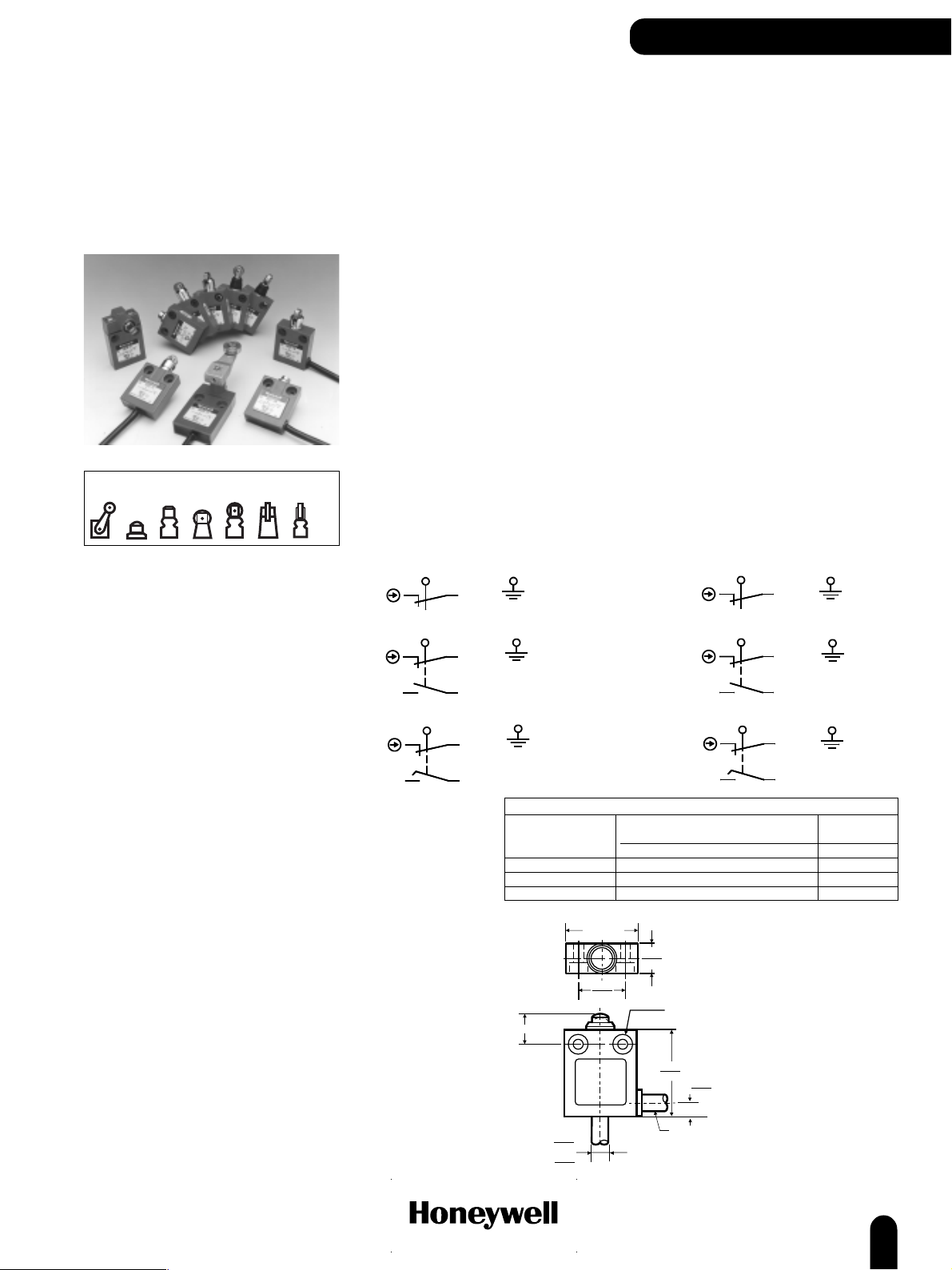
24CE/924CE Series
Miniature Safety
Electromechanical
Switches
Actuators
For position sensing and switching applications requiring direct acting, positive opening contacts the
24CE and 924CE ranges are ideal. They have been tested and approved to meet the requirements of the Low
Voltage directive and positive opening safety contacts per IEC/EN 60947-5-1-3. The devices are CE marked.
The red colour clearly differentiates this safety component in the application. The 924CE range also has UL
and CSA approval.
It is possible for the end user to enhance the safety level of these switches from Category 1 on their own to
Categories 2, 3 or 4 when the switches are used in conjunction with our wide range of FF-SR safety relays to
form a safety system.
Typical applications for these switches would use the roller plunger 24CE2- or 24CE3- style in conjunction
with cams on doors with hinges; or our fixed side rotary 24CE16- style for detection of sliding doors. Also
available are a range of panel mounting or top mounting versions to ensure that small space or difficult
mounting can be simply achieved.
Several contact arrangements are available.
Mechanical life: 10 million
Sealing: standard type: IP66; with boot seal type: IP67
Operating temperature: 24CE 0 °C to 70 °C (32 °F to 158 °F)
Low temperature: -40 °C (-40 °F)
924CE 0 °C to 105 °C (32 °F to 221 °F)
Approvals: 24CE CE
AC15 B300
DC13 R300
924CE CSA, CE
per UL file #E41859, 10 A 250 Vac; 1/3 Hp 125-250 Vac
AC15 B300
DC13 R300
Connection: Harmonised CENELEC 3 or 5 x 0,75 mm
2
cable (24CE)
SJTO 3 or 5 x 18 AWG cable (924CE)
Contacts: Silver
Switching options:
924CE 24CE
Slow action contacts (1NC)
black red
Zb
white
black
Zb
white
Electrical ratings:
green
Slow action contacts (1NC/1NO), Break Before Make (BBM)
redblack
green
white
Zb
black
Slow action contacts (1NC/1NO), Make Before Break (MBB)
red
green
white
Free position
Designation & Utilization
Category
AC15 B300 3 1.5 ---- 3600 360
DC13 R300 0,22 0,1 28 28
120 V 240 V 380 V 480 V 500 V 600 V Make Break
125 V 250 V
40 /
max.
1.58
25 /
0.98
blue
Zb
black
IEC 60947-5-1/EN 60947-5-1
Rated operational current le (A) VA
at rated operational voltage Ue rating
16 /
max.
0.63
2 Holes 5,1 dia
Counter Bored 10,2 dia x 6 deep
(both sides - option 'A' only)
brownblue
green/yellow
brownblue
green/yellow
black
brown
green/yellow
black
1NC: 8,4 /
.33
1NC/1NO: 9,5 /
.374
www.honeywell.com/sensing
49 /
max.
1.93
8 /
0.32
Side exit cable
(Option 'A')
Note: connector versions also available
23
Page 26
COMPACT LIMIT SWITCHES
24CE/924CE Series
OPTIONS
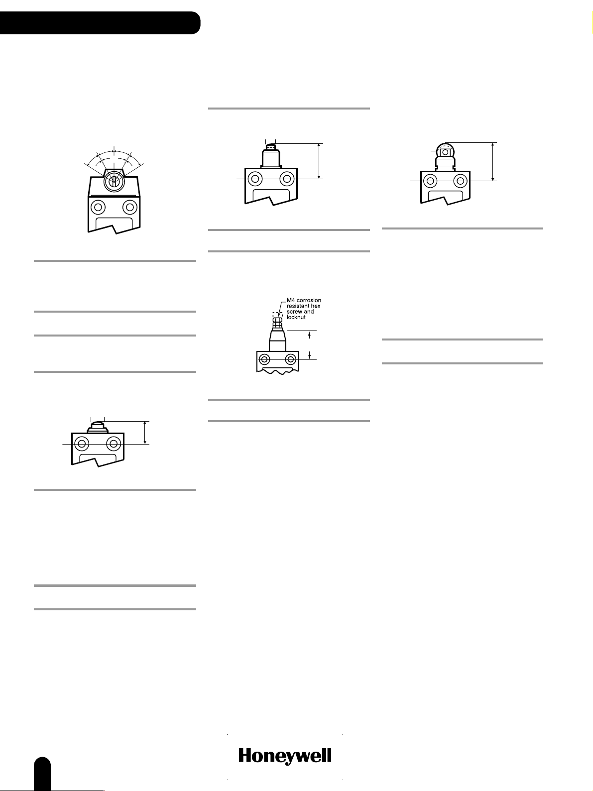
Side rotary
PTPT
DT
DT
OTOT
North America/Global
CABLE LENGTH CONTACT REFERENCE
3 ft 1NC, BBM 924CE16-S3
9 ft 1NC, BBM 924CE16-S9
3 ft 1NC, MBB 924CE16-T3
3 ft 1NC 924CE16-Y3
9 ft 1NC 924CE16-Y9
Europe
CABLE LENGTH CONTACT REFERENCE
1 m 1NC/1NO, BBM 24CE16-S1
1 m 1NC 24CE16-Y1
6 m 1NC 24CE16-Y6
Top pin plunger
ø10
17,5
max.
Top pin plunger, boot sealed
ø7,1
24,3 max.
North America/Global
CABLE LENGTH CONTACT REFERENCE
6 ft 1NC/1NO, BBM 924CE18-S6
Adjustable plunger
26,8
(1.05)
North America/Global
CABLE LENGTH CONTACT OPTION REFERENCE
3 ft 1NC/1NO, BBM low temperature 924CE19-S3L1
Top roller plunger, parallel
ø12,4
30,3
max.
North America/Global
CABLE LENGTH CONTACT OPTION REFERENCE
15 ft 1NC, BBM 924CE2-S15
21 ft 1NC, BBM 924CE2-S21
3 ft 1NC, BBM 924CE2-S3
6 ft 1NC, BBM 924CE2-S6
6 ft 1NC, BBM side exit 924CE2-S6A
9 ft 1NC, BBM 924CE2-S9
25 ft 1NC, MBB 924CE2-T25
25 ft 1NC, MBB side exit 924CE2-T25A
3 ft 1NC, MBB 924CE2-T3
6 ft 1NC, MBB 924CE2-T6
9 ft 1NC, MBB 924CE2-T9
3 ft 1NC 924CE2-Y3
9 ft 1NC 924CE2-Y9
Europe
CABLE LENGTH CONTACT OPTION REFERENCE
1 m 1NC/1NO, BBM 24CE2-S1
2 m 1NC/1NO, BBM 24CE2-S2
2 m 1NC/1NO, BBM side exit 24CE2-S2A
2 m 1NC/1NO, BBM low temperature 24CE2-S2B
3 m 1NC/1NO, BBM 24CE2-S3
6 m 1NC/1NO, BBM 24CE2-S6
2 m 1NC/1NO, MBB 24CE2-T2
1 m 1NC 24CE2-Y1
2 m 1NC 24CE2-Y2
2 m 1NC side exit 24CE2-Y2A
4 m 1NC 24CE2-Y4
6 m 1NC side exit 24CE2-Y6A
North America/Global
CABLE LENGTH CONTACT OPTION REFERENCE
3 ft 1NC, BBM 924CE1-S3
6 ft 1NC, BBM 924CE1-S6
9 ft 1NC, BBM 924CE1-S9
25 ft 1NC, MBB side exit 924CE1-T25A
3 ft 1NC, MBB 924CE1-T3
3 ft 1NC, MBB side exit 924CE1-T3A
6 ft 1NC, MBB side exit 924CE1-T6A
9 ft 1NC, MBB 924CE1-T9
9 ft 1NC, MBB side exit 924CE1-T9A
3 ft 1NC 924CE1-Y3
9 ft 1NC 924CE1-Y9
Europe
CABLE LENGTH CONTACT OPTION REFERENCE
12 m 1NC/1NO, BBM low temperature 24CE1-S12B
2 m 1NC/1NO, BBM 24CE1-S2
2 m 1NC/1NO, BBM side exit 24CE1-S2A
2 m 1NC/1NO, BBM low temperature 24CE1-S2B
3 m 1NC/1NO, BBM 24CE1-S3
6 m 1NC/1NO, BBM 24CE1-S6
1 m 1NC side exit 24CE1-Y1A
2 m 1NC 24CE1-Y2
3 m 1NC 24CE1-Y3
24
www.honeywell.com/sensing
Page 27

Top roller plunger, parallel,
boot sealed
ø12,4
36,1
max.
North America/Global
CABLE LENGTH CONTACT OPTION REFERENCE
3 ft 1NC, BBM 924CE31-S6
20 ft 1NC 924CE31Y20
3 ft 1NC low temperature 924CE31Y3L1
Europe
CABLE LENGTH CONTACT OPTION REFERENCE
1 m 1NC/1NO, BBM 24CE31-S1
2 m 1NC/1NO, BBM 24CE31-S2
2 m 1NC/1NO, BBM low temperature 24CE31-S2B
5 m 1NC/1NO, BBM 24CE31-S5
1 m 1NC 24CE31-Y1
2 m 1NC 24CE31-Y2
3 m 1NC 24CE31-Y3
Top roller plunger, perpendicular
ø12,4
30,3
max.
North America/Global
CABLE LENGTH CONTACT REFERENCE
3 ft 1NC, BBM 924CE3-S3
6 ft 1NC, BBM 924CE3-S6
9 ft 1NC, BBM 924CE3-S9
9 ft 1NC, MBB 924CE3-T9
Europe
CABLE LENGTH CONTACT REFERENCE
2 m 1NC/1NO, BBM 24CE3-S2
1 m 1NC 24CE3-Y1
2 m 1NC 24CE3-Y2
Top roller plunger, perpendicular,
boot sealed
ø12,4
COMPACT LIMIT SWITCHES
Top roller plunger, parallel, panel
mounted
27,7
(1.75)
North America/Global
CABLE LENGTH CONTACT REFERENCE
15 ft 1NC, BBM 924CE28S15
Europe
CABLE LENGTH CONTACT REFERENCE
2 m 1NC/1NO, BBM 24CE28-S2
36,1
max.
Europe
CABLE LENGTH CONTACT REFERENCE
1 m 1NC/1NO, BBM 24CE55-S1
2 m 1NC/1NO, BBM 24CE55-S2
1 m 1NC 24CE55-Y1
www.honeywell.com/sensing
25
Page 28

COMPACT LIMIT SWITCHES
Blank page
26
www.honeywell.com/sensing
Page 29
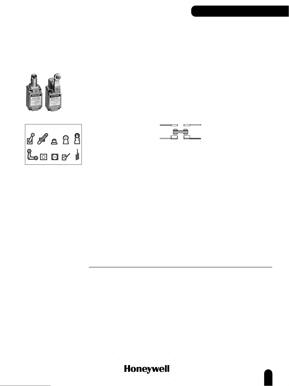
LS Series
Compact Limit
Switches
Actuators
COMPACT LIMIT SWITCHES
LS Series compact limit switches are carefully designed for accurate repeatability under the most stringent conditions.
Compact size and field adjustable features greatly extend the flexibility of these switches. Heads may be positioned at
90° increments. Side rotary models can be adjusted for clockwise and/or counter-clockwise operation. Actuators can be
set and locked in any position through 360°.
The rugged housings and actuator heads are constructed from cast aluminium, capable of withstanding physical abuse.
Protection against oil, water and dust is achieved by O-ring seals on the actuator shaft; a ring seal between head and
body; and a seated compression seal between cover and case.
The LS fits in many places too small for any other fully adjustable limit switch.
Conduit: ½ in - 14 NPT
Sealing: ½ in - 14 NPT conduit NEMA 1, 3, 4, 6, 13
Operating temperature: Standard -29 °C to 71 °C (-20 °F to 160 °F)
Approvals: LS-L UL, CSA
Contacts: Electrical ratings A, B, C, D, E Silver Cadmium Oxide
Switching options: SPDT Single Pole, Double Throw
20 mm conduit IP67
High -29 °C to 121 °C (-20 °F to 250 °F)
Electrical ratings F, G Fine Silver
Snap action contacts (1NC/1NO)
4
3
20 mm
(1)
1
Electrical ratings: A 10 A, 120, 240 or 480 Vac; 1/3 hp, 120 Vac; ¾ hp, 240
B 10 A, 120, 240 or 480 Vac; ¼ hp, 120 Vac; ½ hp, 240
C 10 A, 120 Vac; 1/3 hp, 120 Vac.
D 10 A, 120, 240, 480 Vac; ¼ hp, 120 Vac; ½ hp, 240 Vac;
E 10 A, 120, 240 or 480 Vac; 1/3 hp, 120 Vac; ¾ hp, 240
F UL Rating:
10 A, 125, 250, or 480 Vac; 1/3 hp, 125 Vac; ¾ hp, 250 Vac;
G UL Rating:
10 A, 125, 250 or 480 Vac; ¼ hp, 125 Vac; ½ hp, 250 Vac;
** Resistive rating
(1)
Designed for use with inductive loads such as relays, contactors, motors and solenoids. Honeywell does
recommend the use of silver cadmium oxide switch contacts in non-arcing loads. Non-arcing loads are
generally loads less than 12 volts and/or 0.5 amp.
2
Vac;
0.8 A, 115 Vdc**; 0.4 A, 230 Vdc;** 0.1 A, 550 Vdc;**
Pilot Duty, 600 Vac max.
Vac.
Pilot Duty, 600 Vac max.
0.8 A, 115 Vdc**; 0.4 A, 230 Vdc**; 0.1 A, 550 Vdc**;
Pilot Duty, 600 Vac max.
Vac.
Pilot Duty, 600 Vac max.
0.8 A, 125 Vdc**; 0.4 A, 250 Vdc**
0.8 A, 125 Vdc**; 0.4 A, 250 Vdc**
not
www.honeywell.com/sensing
27
Page 30
COMPACT LIMIT SWITCHES
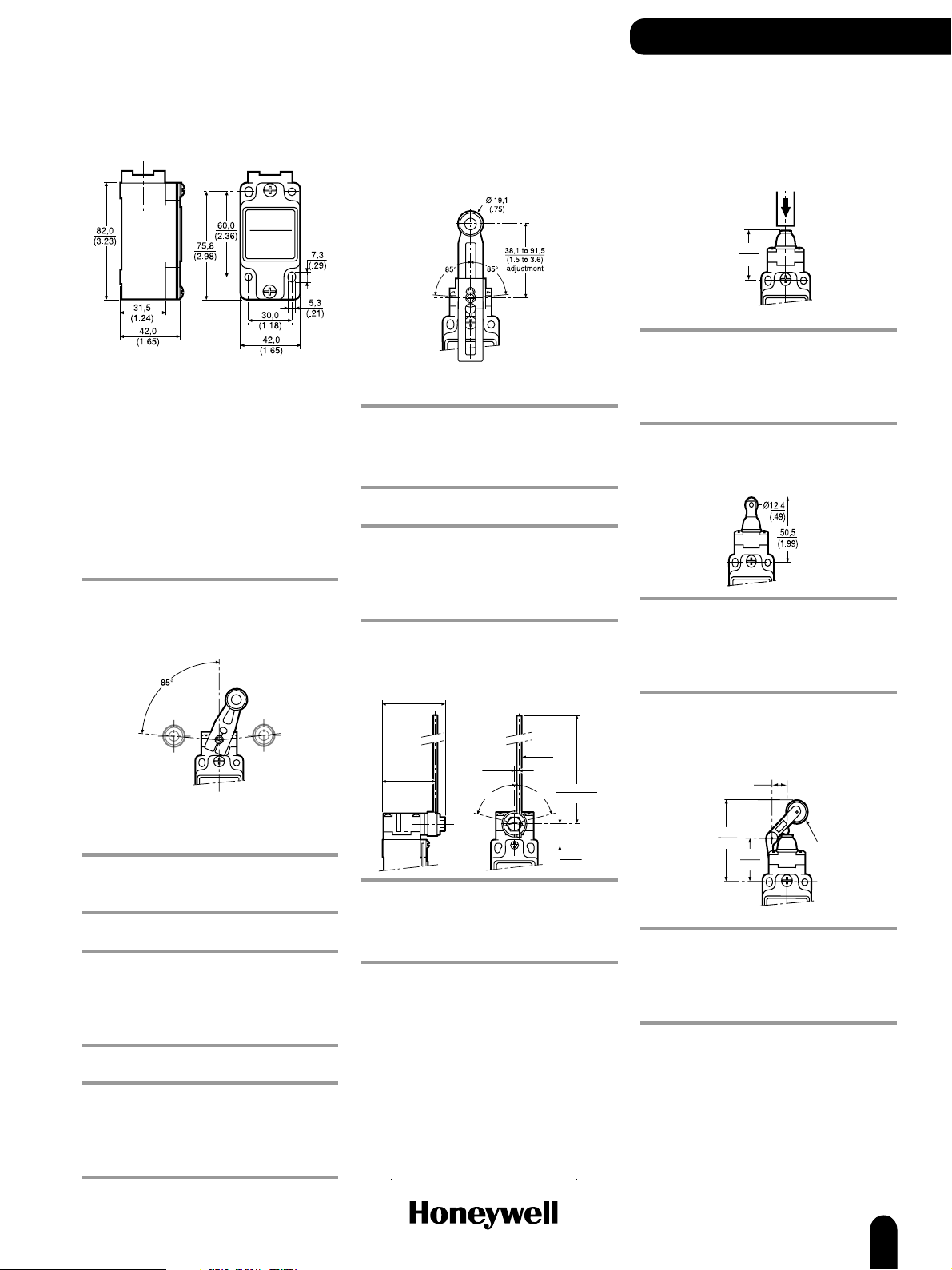
LS Series
Side rotary actuated switches
OPTIONS
Fixed length lever
Operating force max. (OF): Standard 13,3 N (3.0 lb)
Low 5,0 N (18 oz)
Pretravel max. (PT): Standard 20°
Low 5°
Overtravel min. (OT) 30°
Differential travel max. (DT): Standard 12°
Low 4°
Switching options: SPDT
Lever: Aluminium, steel roller
Adjustable roller lever
Operating force max. (OF): Standard 13,3 N (3.0 lb)
Low 5,0 N (18 oz)
Pretravel max. (PT): Standard 20°
Low 5°
Overtravel min. (OT) 30°
Differential travel max. (DT): Standard 12°
Low 4°
Switching options: SPDT
Lever: Aluminium, nylon roller
CONDUIT ELECTRICAL RATING REFERENCE
Low PT/OF B 1LS131
Low PT B 1LS19
Low PT 20 mm B 1LS19-4C
High temperature A 1LS243
High temperature 20 mm A 1LS243-4C
Indicator light C 1LS501
Low OF A 1LS6
20 mm A 1LS1-4C
A 1LS1
F 1LS1-L
CONDUIT ELECTRICAL RATING REFERENCE
Low PT B 1LS58
Low OF/PT/DT B 1LS59
20 mm A 1LS3-4C
A1LS3
F 1LS3-L
28
www.honeywell.com/sensing
Page 31

COMPACT LIMIT SWITCHES
No lever
Note: Levers are ordered separately (see pages 69-71
for details)
Operating force max. (OF): Standard 0,51 N m (4.5 in lb)
Pretravel max. (PT): Standard 20°
Overtravel min. (OT) Standard 30°
Differential travel max. (DT): Standard 12°
Switching options: SPDT
Low with standard PT 0,21 N m (30 in oz)
Low with low PT 0,11 N m (1 in lb)
Low 5°
Maintained contact 55°
Maintained contact 35°
Low PT 4°
Maintained contact 20°
Maintained contact
SPDT contact
CONDUIT ELECTRICAL RATING REFERENCE
Low OF A 1LS23
Low OF/PT B 1LS56
Low PT B 1LS9
20 mm A 1LS2-4C
A 1LS2
F 1LS2-L
Maintained contact
CONDUIT ELECTRICAL RATING REFERENCE
A 6LS2
F 6LS2-L
Adjustable rod
Operating force max. (OF): Standard 1,39 N (5 oz)
Pretravel max. (PT): Standard 20°
Overtravel min. (OT) 30°
Differential travel max. (DT): Standard 12°
Switching options: SPDT
Lever: Aluminium rod
CONDUIT ELECTRICAL RATING REFERENCE
Low PT B 1LS47
Low PT/OF/DT B 1LS53
20 mm A 1LS10-4C
A 1LS10
F 1LS10-L
Low 0,83 Nm (3 oz)
Low 5°
Low 4°
Side rotary, yoke lever, maintained contact
Operating force max. (OF): 8,9 N (2.0 lb)
Pretravel max. (PT): 55°
Switching options: Maintained
Lever: 6LS1 Steel rollers on opposite sides of arm
6LS3 Nylon rollers on same side of arm
CONDUIT ELECTRICAL RATING REFERENCE
20 mm A 6LS1-4C
www.honeywell.com/sensing
A 6LS1
A 6LS3
29
Page 32

COMPACT LIMIT SWITCHES
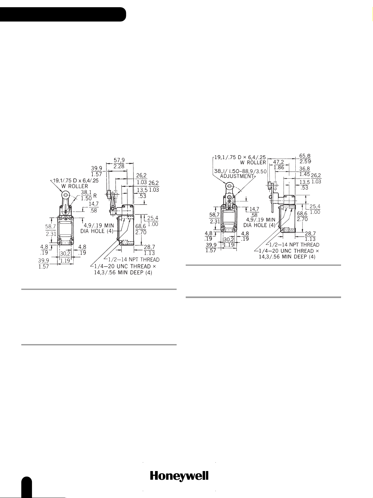
LS Series
Plunger actuated switches
OPTIONS
Top pin plunger
Operating force max. (OF): Standard 31,14 N (7 lb)
Pretravel max. (PT): 1,65 mm (0.065 in)
Overtravel min. (OT) Standard 6,35 mm (0.25 in)
Differential travel max. (DT): Standard 0,51 mm (0.020 in)
Switching options: SPDT
CONDUIT ELECTRICAL RATING REFERENCE
Low OF/OT/DT E 2LS111
20 mm A 2LS1-4C
A 2LS1
F 2LS1-L
Low 10 N (36 oz)
Low 5,56 mm (0.219 in)
Low 0,23 mm (0.009 in)
Side pin plunger
Operating force max. (OF): 40,03 N (9 lb)
Pretravel max. (PT): 2,8 mm (0.110 in)
Overtravel min. (OT) 6,35 mm (0.25 in)
Differential travel max. (DT): 1,02 mm (0.040 in)
Switching options: SPDT
CONDUIT ELECTRICAL RATING REFERENCE
20 mm A 4LS1-4C
A4LS1
Side roller plunger
Top roller plunger
Operating force max. (OF): 31,14 N (7 lb)
Pretravel max. (PT): 1,65 mm (0.065 in)
Overtravel min. (OT) 5,56 mm (0.219 in)
Differential travel max. (DT): 0,51 mm (0.020 in)
Switching options: SPDT
CONDUIT ELECTRICAL RATING REFERENCE
20 mm A 5LS1-4C
A 5LS1
F 5LS1-L
Operating force max. (OF): 40,03 N (9 lb)
Pretravel max. (PT): 2,8 mm (0.110 in)
Overtravel min. (OT) 5,56 mm (0.219 in)
Differential travel max. (DT): 1,02 mm (0.040 in)
Switching options: SPDT
CONDUIT ELECTRICAL RATING REFERENCE
20 mm A 3LS1-4C
A3LS1
30
www.honeywell.com/sensing
Page 33

Wobble actuated switches
191,3
(7.53)
These switches will operate by moving actuator in any
direction except direct pull.
Operating force max. (OF): 1,39 N (5 oz)
Pretravel max. (PT): 28,6 mm (1,125 in)
Switching options: SPDT
OPTIONS
COMPACT LIMIT SWITCHES
Flexible cable
CONDUIT ELECTRICAL RATING REFERENCE
20 mm D 8LS1-4C
Spring rod
(0.189 ±0.003)
141,0 ±2,54
(5,550 ±0.10)
D 8LS1
G 8LS1-L
Ø 4,80 ±0.08
Coil spring
Ø 6,17 ±0.08
(0.264 ±0.003)
141,0 ±2,54
(5,550 ±0.10)
CONDUIT ELECTRICAL RATING REFERENCE
20 mm D 8LS152-4C
D 8LS152
Steel wire
Operating force max. (OF): 0,28 N (1 oz)
Pretravel max. (PT): 63,5 mm (2.5 in)
CONDUIT ELECTRICAL RATING REFERENCE
20 mm D 8LS3-4C
D 8LS3
CONDUIT ELECTRICAL RATING REFERENCE
20 mm D 8LS125-4C
www.honeywell.com/sensing
D 8LS125
31
Page 34

PRECISION LIMIT SWITCHES
BF Series Plastic Enclosed Basic Switches are available with a wide variety of actuators, and are designed for easy
BF Series
Plastic
Enclosed Basic
Switches
Actuators
mounting and wiring. BF switches are designed to allow mounting with the cover either towards or away from the
mounting surface.
Switches with lever type actuators are adjustable in two directions. The entire actuator can be rotated around its
mounting bushing, and the angle of the lever can also be changed.
Sealing: NEMA 1, 3, 4, 13
Operating temperature: -32 °C to 71 °C (-25 °F to 160 °F)
Approvals: UL
Termination: ½ in - 14NPT
Contacts: Silver
Electrical ratings: A 11 A - 125 Vac, 250 Vac or 277 Vac
Switching options:
SPDT Single Pole, Double Throw,
B 5 A - 125 Vac, 250 Vac or 277 Vac
Snap action contacts (1NC/1NO)
Plunger actuated switches
OPTIONS
Top pin plunger
14,3
0.56
65,28
2.57
44,5
1.75
4,9
9,5
0.19
0.38
Operating force max. (OF): 12,23 N (44 oz)
Differential travel max. (DT): 0,64 mm (0.025 in)
ACTUATOR POSITION ELECTRICAL RATING REFERENCE
Left B BFL1-BP1
Right B BFR1-BP1
Ø 7,1
58,7
2.31
73,5
2.89
0.28
Max.
17,5
0.69
15,5
0.61
35,1
1.38
Conduit thread
Top roller arm, adjustable
18,3
0.72
39,9
1.57
23,1
Max.
0.91
17,5
73,6
2.90
44,5
1.75
4,9
0.19
9,5
0.38
58,7
2.31
73,5
2.89
Operating force max. (OF): 10,56 N (38 oz)
Differential travel max. (DT): 1,65 mm (0.065 in)
ACTUATOR POSITION ELECTRICAL RATING REFERENCE
Left B BFL1-BL1
Right B BFR1-BL1
0.69
15,5
0.61
35,1
1.38
32
www.honeywell.com/sensing
Page 35

PRECISION LIMIT SWITCHES
C
Plunger actuated switches
(continued)
Top roller arm, adjustable, one
way
39,6
19,05
0.75
17,5
0.69
35,1
1.38
14,73
Ø 15,5
0.58
0.61
58,7
2.31
73,5
2.89
Operating force max. (OF):
Left 3,61 N (13 oz)
Right 10,56 N (38 oz)
ACTUATOR ELECTRICAL REFERENCE
POSITION RATING
Left B BFL1-BL3
Right B BFR1-BL3
18,3
0.72
1.56
9,5
0.38
180˚
4,9
0.19
44,5
1.75
32,26
1.27
73,6
2.90
Wobble actuated switches
Operating force max. (OF): 1,95 N (7 oz)
OPTIONS
Coil spring
14,3
0.56
169,9
6.69
44,5
1.75
4,9
9,5
0.19
0.38
ACTUATOR ELECTRICAL REFERENCE
POSITION RATING
Left A BFL1-AW1
Left B BFL1-BW1
Right B BFR1-BW1
58,7
2.31
73,5
2.89
Ø 7,1
0.28
Max.
17,5
0.69
15,5
0.61
35,1
1.38
Spring wire
14,3
0.56
Ø 1,02
0.05
168,8
6.65
17,5
0.69
14,7
0.58
15,5
0.61
35,1
1.38
44,5
1.75
4,9
9,5
0.38
58,7
2.31
73,5
2.89
0.19
ACTUATOR ELECTRICAL REFERENCE
POSITION RATING
Left B BFL1-BW4
Right B BFR1-BW4
Low force rod
250˚
18,3
0.72
14,73
0.58
17,5
0.69
35,1
1.38
Ø 15,5
0.61
73,6
2.90
44,5
1.75
4,9
0.19
9,5
0.38
58,7
2.31
73,5
2.89
Operating force max. (OF):
Left 10,56 N (38 oz)
Right 3,61 N (13 oz)
ACTUATOR ELECTRICAL REFERENCE
POSITION RATING
Left B BFL1-BL2
Right B BFR1-BL2
Plastic
249,25
9.81
44,5
1.75
4,9
0.19
0.38
9,5
14,3
Ø 7,1
0.56
0.28
58,7
2.31
Type -BW3
73,5
2.89
17,5
0.69
15,5
0.61
35,1
1.38
ACTUATOR ELECTRICAL REFERENCE
POSITION RATING
Left, A BFL1-AW2
179,3 mm (7.06 in) length rod
Left, B BFL1-BW3
249,25 mm (9.8 in) length rod
www.honeywell.com/sensing
33
Page 36

PRECISION LIMIT SWITCHES
BZE/DTE Series
Compact Enclosed
Switches
Actuators
The BZE/DTE Series general purpose enclosed limit switches offer precision operation and sturdy
actuation in a compact but rugged aluminium housing. The large wiring enclosure means that the user
can get access to wire the device simply. The switch incorporates high repeatability of the switch point
early in the travel of the switch. This is achieved through a very tolerant over-travel mechanism which
ensures that application drift will not affect long term accuracy of the switch.
Conduit: ½ in - 14 NPT
Sealing: E6 NEMA 1
V6 NEMA 1, 3
Operating temperature: Standard -32 °C to 71 °C (-25 °F to 160 °F)
Low -40 °C to 71°C (-40 °F to 160 °F)
Approvals: UL, CSA, CE
Contacts: Electrical ratings A, B, C Silver
Electrical rating D Gold
Switching options:
SPDT Single Pole, Double Throw
Snap action contacts (1NC/1NO)
DPDT Double Pole, Double Throw
Snap action contacts (2NC/2NO)
Electrical ratings:
A UL/CSA Rating: 15 A, 125, 250 or 480 Vac:
1
/8 Hp, 125 Vac: ¼ Hp, 250 Vac:
½ A, 125 Vdc: ¼ A, 250 Vdc
B UL/CSA Rating: 10 A, 125 or 250 Vac:
C UL/CSA Rating: 15 A, 125, 250 or 480 Vac;
D UL/CSA Rating: 1 A - 125 Vac
0.3 A, 125 Vdc: 0.15 A, 250 Vdc
¼ Hp, 125 Vac; ½ Hp, 250 Vac;
½ A, 125 Vdc; ¼ A, 250 Vdc
2 A, 600 Vac:
34
www.honeywell.com/sensing
Page 37

PRECISION LIMIT SWITCHES
E6/V6
E6 (side mount) and V6 (flange mount) switches are offered with or without actuator seal boots. Both have a combination insulator/ seal cemented inside the
bottom enclosure. Lead washers are used to seal the mounting holes on side mount switches. All side mount switches are installed with #6 screws, except the
BZE6-2RN7 (#8 screws). Removal of the bottom enclosure exposes the terminals for easy wiring.
Momentary contact
OPTIONS
Top pin plunger
2,0
REF
23,4
(0.08)
43,7
(1.72)
(1.00)
25,4
(1.00)
25,4
OP
19,0
(0.75)
21,1
(0.83)
(0.92)
77,2
(3.04)
1/2-14 NPT
Threads
Side mount
with boot seal
22,6
(0.89)
Ø 8,4
(0.33)
25,4
(1.00)
63,5
(2.50)
OP
44,4
(1.75)
10,6
(0.42)
77,2
(3.04)
without boot seal
Ø 8,4
(0.33)
1/2-14 NPT
22,6
(0.89)
Flange mount
Threads
4,3
(0.17)
41,4
(1.63)
Ø (2)
25,4
(1.00)
54,1
(2.13)
With boot seal
Operating force max. (OF):SPDT Standard 2,50 N to 6,67 N (9 oz to 24 oz)
Pretravel max. (PT): SPDT 1,98 mm (0.078 in)
Overtravel min. (OT): SPDT 5,56 mm (0.219 in)
Differential travel max. (DT): SPDT 0.05 mm (0.002 in)
SPDT Low temperature 4,17 N to 10,84 N (15 oz to 39 oz)
DPDT 6,95 N to 16,4 N (25 oz to 59 oz)
DPDT 2,8 mm (0.110 in)
DPDT 3,18 mm (0.125 in)
DPDT 1,52 mm (0.060 in)
Side mount
CONTACT ELECTRICAL RATING REFERENCE
SPDT A BZE6-2RN
Low temperature/High OF SPDT A BZE6-2RN34
#8 screws SPDT A BZE6-2RN7
Gold contacts SPDT D BZE6-2RN72
DPDT B DTE6-2RN
Flange mount
CONTACT ELECTRICAL RATING REFERENCE
SPDT A BZV6-2RN
DPDT B DTV6-2RN
Top roller plunger, parallel
23,4
56,6
OP
(2,23)
19,0
(0.75)
25,4
(1.00)
25,4
(1.00)
with boot seal
(0.92)
12,7 (0.50) Ø
77,2
(3.04)
Side mount
X
4,6 (0.18) W
Roller
1/2-14 NPT
Threads
22,6
(0.89)
25,4
(1.00)
49,61
OP
(1.953)
19,0
(0.75)
25,4
(1.0)
without boot seal
12,7 (0.50) Ø
Wide Roller
69,6
(2.740)
Side mount
X
4,6 (0.18)
With boot seal
Operating force max. (OF): SPDT 2,50 N to 6,67 N (9 oz to 24 oz)
Pretravel max. (PT): SPDT 1,98 mm (0.078 in)
Overtravel min. (OT): SPDT 5,56 mm (0.219 in)
Differential travel max. (DT): SPDT 0,01 mm to 0,05 mm
DPDT 5,56 N to 13,34 N (20 oz to 48 oz)
DPDT 2,8 mm (0.110 in)
DPDT 3,18 mm (0.125 in)
(0.0004 in to 0.0020 in)
DPDT 1,52 mm (0.060 in)
Side mount
CONTACT ELECTRICAL RATING REFERENCE
SPDT A BZE6-2RN80
DPDT B DTE6-2RN80
Flange mount
CONTACT CONDUIT ELECTRICAL RATING REFERENCE
SPDT A BZV6-2RN80
15,75
(0.62)
Ø
22,6
(0.89)
Without boot seal
Operating force max. (OF): SPDT 2,50 N to 3,61 N (9 oz to 13 oz)
Pretravel max. (PT): SPDT 0,38 mm (0.015 in)
Overtravel min. (OT): SPDT 5,56 mm (0.219 in)
Differential travel max. (DT): SPDT 0,05 mm (0.002 in)
DPDT 5,56 N to 11,12 N (20 oz to 40 oz)
DPDT 3,81 mm (0.150 in)
DPDT 2,24 mm (0.088 in)
DPDT 1,52 mm (0.060 in)
Side mount
CONTACT ELECTRICAL RATING REFERENCE
SPDT A BZE6-2RQ
DPDT B DTE6-2RQ
Flange mount
CONTACT ELECTRICAL RATING REFERENCE
SPDT A BZV6-2RQ
www.honeywell.com/sensing
Without boot seal
Operating force max. (OF): SPDT 2,50 N to 3,61 N (9 oz to 13 oz)
Pretravel max. (PT): SPDT 0,38 mm (0.015 in)
Overtravel min. (OT): SPDT 3,55 mm (0.140 in)
Differential travel max. (DT): SPDT 0,05 mm (0.002 in)
DPDT 6,67 N to 13,34 N (24oz to 48 oz)
DPDT 3,58 mm (0.141 in)
DPDT 3,18 mm (0.125 in)
DPDT 1,52 mm (0.060 in)
Side mount
CONTACT CONDUIT ELECTRICAL RATING REFERENCE
Field adjustable roller SPDT A BZE6-2RQ9
Field adjustable roller DPDT B DTE6-2RQ9
SPDT A BZE6-2RQ8
Flange mount
CONTACT CONDUIT ELECTRICAL RATING REFERENCE
SPDT A BZV6-2RQ8
35
Page 38

PRECISION LIMIT SWITCHES
BZE/DTE Series
E6/V6 Momentary contact (continued)
Top roller plunger, perpendicular
12,7 (0.50) Ø
X
4,6 (0.18) W
77,2
(3.04)
Roller
22,6
(0.89)
Flange mount
without boot seal
56,6
(2,23)
(1.00)
25,4
(1.00)
25,4
OP
19,0
(0.75)
Side mount
with boot seal
With boot seal
Operating Force max. (OF): 2,60 N to 6,67 N (9 oz to 24 oz)
Pretravel max. (PT): 1,98 mm (0.078 in)
Overtravel min. (OT): 5,56 mm (0.219 in)
Differential travel max. (DT): 0,01 mm to 0,05 mm
(0.0004 in to 0.0020 in)
Side mount
CONTACT ELECTRICAL RATING REFERENCE
SPDT A BZE6-2RN81
Without boot seal
Operating Force max. (OF): SPDT 2,50 N to 3,61 N (9 oz to 13 oz)
Pretravel max. (PT): SPDT 0,38 mm (0.015 in)
Overtravel min. (OT): SPDT 3,55 mm (0.140 in)
Differential travel max. (DT): SPDT 0,05 mm (0.002 in)
DPDT 6,67 N to 13,34 N (24 oz to 48 oz)
DPDT 3,58 mm (0.141 in)
DPDT 3,18 mm (0.125 in)
DPDT 1,52 mm (0.060 in)
Side mount
CONTACT ELECTRICAL RATING REFERENCE
SPDT A BZE6-2RQ81
DPDT B DTE6-2RQ81
Roller arm, adjustable
Side mount
without boot seal
Operating temperature: Standard -32 °C to 71 °C (-25 °F to 160 °F)
Low -40 °C to 71 °C (-40 °F to 160 °F)
Roller: Steel
Flange mount
with boot seal
With boot seal
Operating Force max. (OF): 2,78 N to 5,56 N (10 oz to 20 oz)
Pretravel max. (PT): 4,78 mm (0.188 in)
Overtravel min. (OT): 5,56 mm (0.219 in)
Differential travel max. (DT): SPDT 0,15 mm (0.006 in)
DPDT 4,19 mm (0.165 in)
Side mount
Operating Force max. (OF): DPDT 13,34 N (48 oz)
Pretravel max. (PT): DPDT 7,92 mm (0.312 in)
CONTACT ELECTRICAL RATING REFERENCE
SPDT A BZE6-2RN2
Low temperature SPDT A BZE6-2RN234
DPDT B DTE6-2RN2
Flange mount
Operating Force max. (OF): DPDT 2,78 N to 8,34 N (10 oz to 30 oz)
Pretravel max. (PT): DPDT 6,76 mm (0.266 in)
CONTACT ELECTRICAL RATING REFERENCE
SPDT A BZV6-2RN2
DPDT B DTV6-2RN2
Flange mount
CONTACT ELECTRICAL RATING REFERENCE
SPDT A BZV6-2RQ81
36
Without boot seal
Operating Force max. (OF): 2,78 N to 5,00 N (10 oz to 20 oz)
Pretravel max. (PT): 4,78 mm (0.188 in)
Overtravel min. (OT): 5,56 mm (0.219 in)
Differential travel max. (DT): 0,15 mm (0.006 in)
Side mount SPDT A BZE6-2RQ2
Flange mount SPDT A BZV6-2RQ2
CONTACT ELECTRICAL RATING REFERENCE
www.honeywell.com/sensing
Page 39

Flange mount
with boot seal
PRECISION LIMIT SWITCHES
One way roller lever
Side mount
with boot seal
With boot seal
Operating Force max. (OF): 2,22 N to 5,56 N (8 oz to 20 oz)
Pretravel max. (PT): 5,94 mm (0.234 in)
Overtravel min. (OT): 5,56 mm (0.219 in)
Differential travel max. (DT): 0,15 mm (0.006 in)
Side mount SPDT A BZE6-2RN28
CONTACT ELECTRICAL RATING REFERENCE
Rod lever
Pretravel max. (PT): 18,24 mm (0.718 in)
Overtravel min. (OT): 21,29 mm (0.838 in)
Differential travel max. (DT): 5,82 mm (0.229 in)
Manual palm button
78,5
3.09
44,4
1.75
36,6
1.44
18,3
0.72
31,8
1.25
77,2
3.04
Side mount
with boot seal
1/2 - 14 NPSM
5 THREADS MIN
4,3
0.17
22,6
0.89
41,4
1.63
Ø (2)
38,1
1.50
25,4
1.00
54,1
2.13
With boot seal
Operating force max. (OF): 2,78 N to 5,56 N (10 oz to 20 oz)
Pretravel max. (PT): 4,78 mm (0.188 in)
Overtravel min. (OT): 5,56 mm (0.219 in)
Differential travel max. (DT): 0,15 mm (0.006 in)
Flange mount SPDT A BZV6-2RN4
CONTACT ELECTRICAL RATING REFERENCE
Wobble, coil spring
These switches will operate by moving actuator in any direction except direct
pull.
152,4
(6.0)
18,29
(0.72)
250˚
53,19
(2.09)
Ø 15,75
(0.62)
Flange mount
without boot seal
19,05
(0.75)
25,4
(1.00)
69,60
(2,74)
77,2
(3.04)
Side mount
with boot seal
With boot seal
Operating force max. (OF): 0,83 N to 1,95 N (3 oz to 7 oz)
Side mount SPDT A BZE6-2RN62
Flange mount SPDT A BZV6-2RN62
CONTACT ELECTRICAL RATING REFERENCE
Without boot seal
Operating force max. (OF): 0,56 N to 1,39 N (2 oz to 5 oz)
Side mount SPDT A BZE6-2RQ62
Flange mount SPDT A BZV6-2RQ62
CONTACT ELECTRICAL RATING REFERENCE
22,6
(0.89)
With boot seal
Operating force max. (OF): 1,95 N (7 oz)
Pretravel max. (PT): 15°
Side mount SPDT A BZE6-2RN18
Flange mount SPDT A BZV6-2RN18
CONTACT ELECTRICAL RATING REFERENCE
www.honeywell.com/sensing
37
Page 40

PRECISION LIMIT SWITCHES
BZE/DTE Series
E6/V6 Maintained contact (reset) switches
The switches shown below provide maintained contact after the operating
force on either top or bottom plunger is released.
Note: The top plungers on these switches provide more accurate and uniform
operation than the “reset” plungers and should be used when closely held
operating characteristics are required.
Switching:
SPDT Single Pole, Double Throw
OPTIONS
(1NC/1NO) Maintained
Top pin plunger
Side mount
with boot seal
Flange mount
without boot seal
Side mount
Operating force max. (OF): With boot seal 1,67 N to 5,56 N (6 oz to 20 oz)
Pretravel max. (PT): With boot seal 1,98 mm (0.078 in)
Overtravel min. (OT): 4,75 mm (0.187 in)
With boot seal SPDT Maintained C BZE6-RNX1
Without boot seal SPDT Maintained C BZE6-RQX2
CONTACT ELECTRICAL RATING REFERENCE
Without boot seal 1,67 N to 2,64 N (6 oz to 9.5 oz)
Without boot seal 0.30 mm (0.012 in)
Top roller plunger
Ø 12,7 (0.50) x 4,6 (0.18)
Wide roller
Ø 15,75
(0.62)
22,6
(0.89)
Ø 25,4
(1.0)
14,22
(0.56)
40,08
23,19
(0.913)
69,59
(2.74)
Side mount
without boot seal
56,69
(2.232)
53,19
(2.094)
Reset
FP
Side mount
with boot seal
25,4
(1.00)
19,0
(0.75)
(1.58)
Roller arm, adjustable
Flange mount
with boot seal
Side mount
without boot seal
Side mount
Operating Force max. (OF): With boot seal 4,45 N (16 oz)
Pretravel max. (PT): 4,78 mm (0.188 in)
Overtravel min. (OT): 5,56 mm (0.219 in)
With boot seal Maintained C BZE6-RN2X1
Without boot seal Maintained C BZE6-RQ2X2
CONTACT CONDUIT ELECTRICAL RATING REFERENCE
Without boot seal 3,34 N (12 oz)
Side mount
Operating force max. (OF): With boot seal 3,34 N to 15,57 N (12 oz to 56 oz)
Pretravel max. (PT): With boot seal 1,98 mm (0.078 in)
Overtravel min. (OT): With boot seal 4,75 mm (0.187 in)
With boot seal SPDT C BZE6-RN80X2
Without boot seal SPDT C BZE6-RQ8X2
CONTACT CONDUIT ELECTRICAL RATING REFERENCE
38
Without boot seal 1,67 N to 2,64 N (6 oz to 9.5 oz)
Without boot seal 0,30 mm (0.012 in)
Without boot seal 3,55 mm (0.140 in)
www.honeywell.com/sensing
Page 41

E7 Metal standard enclosed switch
PRECISION LIMIT SWITCHES
Mechanical life: 10 million
Sealing: Without boot seal IP50 Standard
With boot seal IP65 Sealed
Operating temperature: -30 °C to 70 °C (-22 °F to 158 °F)
Approvals: IEC 60947-5-1
EN 60947-5-1
Switching options:
SPDT Single Pole, Double Throw
Snap action contacts (1NC/1NO)
DPDT Double Pole, Double Throw
Snap action contacts (2NC/2NO)
OPTIONS
Top pin plunger
With boot seal
Without boot seal
1,93
(0.076)
Pretravel
38,58
OP
(1.519)
13,97
(0.55)
25,4
(1.00)
5,84
(0.23)
CONTACT CONDUIT ELECTRICAL RATING REFERENCE
SPDT PG 13.5 BZE7-2RN-PG
SPDT 20 mm BZE7-2RN-C
DPDT PG 13.5 DTE7-2RN-PG
CONTACT CONDUIT ELECTRICAL RATING REFERENCE
SPDT PG 13.5 BZE7-2RQ-PG
4,06
(0.16)
Ø 8,38
(0.33)
76,40
(3,01)
12,7
(0.50)
Ø 14,73
(0.58)
Actuators
Top roller plunger, perpendicular, without boot seal
0,38
(0.015)
Pretravel
44,53
OP
(1.75)
13,97
(0.55)
25,4
(1.00)
5,84
(0.23)
CONTACT CONDUIT ELECTRICAL RATING REFERENCE
SPDT PG 13.5 BZE7-2RQ81-PG
4,06
(0.16)
Ø 12,7 x 4,57
(0.50 x 0.18)
76,40
(3,01)
Wide roller
12,7
(0.50)
Ø 14,73
(0.58)
Top roller lever, boot seal
Ø 19,05 x 7,92 wide roller
(Ø 0.75 x 0.312)
39,88
(1.57)
18,29
(0.72)
225˚
48,11
(1.894)
13,97
(0.55)
25,4
(1.00)
5,84
(0.23)
CONTACT CONDUIT ELECTRICAL RATING REFERENCE
SPDT PG 13.5 BZE7-2RN2-PG
SPDT 20 mm BZE7-2RN2-C
4,06
(0.16)
76,40
(3,01)
24,38
(0.91)
12,7
(0.50)
Ø 14,73
(0.58)
Wobble, coil spring, boot seal
Top roller plunger, parallel, without boot seal
3,8
(0.15)
Pretravel
44,5
OP
(1.75)
13,97
(0.55)
25,4
(1.00)
5,84
(0.23)
CONTACT CONDUIT ELECTRICAL RATING REFERENCE
SPDT PG 13.5 BZE7-2RQ8-PG
4,06
(0.16)
Ø 12,7 x 4,5 wide roller
(Ø 0.50 x 0.18)
76,40
(3,01)
12,7
(0.50)
Ø 14,73
(0.58)
www.honeywell.com/sensing
151,13
(5.95)
13,97
(0.55)
25,4
(1.00)
5,84
(0.23)
CONTACT CONDUIT ELECTRICAL RATING REFERENCE
SPDT PG 13.5 BZE7-2RN18-PG
4,06
(0.16)
76,40
(3,01)
12,7
(0.50)
Ø 14,73
(0.58)
39
Page 42

PRECISION LIMIT SWITCHES
BAF/DTF
Series
High Capacity
Enclosed
Switches
Actuators
The BAF/DTF Series is available with or without boot seals. The elastomer
boot on sealed actuator versions protects the actuating mechanism and the
internal basic switch from contamination. They are therefore suitable for
wash-down applications. Both sealed and unsealed versions are available with
the actuators on the right or left hand side.
The cover plate is removable to allow ease of wiring and switch replacement
without having to dismount the housing.
The BAF/DTF Series is suitable for use in packaging equipment, farm
machinery, conveyors, overhead cranes and hoists.
Approvals: UL, CSA
Sealing: NEMA 1, 3, 4, 13
-2RQ9 NEMA 1
Operating temperature: -32 °C to 71 °C (-25 °F to 160 °F)
Conduit: ½ in - 14 NPT
Contacts: Silver
Electrical ratings: B UL/CSA Rating: 10 A, 125 or 250 Vac;
0.3 A, 125 Vdc; 0.15 A,
250 Vdc.
D UL/CSA Rating: 20 A, 125, 250 or 480 Vac;
1 Hp, 125 Vac; 2 Hp, 250 Vac;
½ A, 125 Vdc; ¼ A, 250 Vdc;
Lamp Load - 10 A, 125 Vac.
Switching options:
D SPDT Single Pole, Double Throw
Snap action contacts (1NC/1NO)
B DPDT Double Pole, Double Throw
Snap action contacts (2NC/2NO)
Momentary contact
OPTIONS
Top pin plunger
Left-hand Right-hand
*28,2
on DTF2 Types
1.11
With boot seal
Operating force max. (OF): BAF/DTF 11,2 N (2.5 lb)
Pretravel max. (PT): BAF 2,39 mm (0.094 in)
Overtravel min. (OT): BAF 5,56 mm (0.219 in)
Differential travel max. (DT): BAF 0,26 mm (0.010 in)
Operating position (OP): BAF 53,19 mm (2.094 in)
ACTUATOR POSITION CONTACT ELECTRICAL RATING REFERENCE
Right SPDT D BAF1-2RN-RH
Left SPDT D BAF1-2RN-LH
Right DPDT B DTF2-2RN-RH
Left DPDT B DTF2-2RN-LH
DTF 3,59 mm (0.141 in)
DTF 3,96 mm (0.156 in)
DTF 1,53 mm (0.060 in)
DTF 52,07 mm (2.050 in)
40
www.honeywell.com/sensing
Page 43

Momentary contact (continued)
PRECISION LIMIT SWITCHES
Top roller plunger, parallel
Right-hand Left-hand
*28,2
1.11
on DTF2 Types
O-ring actuator seal
Operating force max. (OF): BAF/DTF 35,6 N (8.0 lb)
Pretravel max. (PT): BAF/DTF 3,18 mm (0.125 in)
Overtravel min. (OT): BAF 4,75 mm (0.187 in)
DTF 3,18 mm (0.125 in)
Differential travel max. (DT): BAF 0,19 mm (0.0075 in)
DTF 1,53 mm (0.060 in)
Operating position (OP): BAF 64,69 mm (2.547 in)
DTF 63,88 mm (2.515 in)
ACTUATOR POSITION CONTACT ELECTRICAL RATING REFERENCE
Right SPDT D BAF1-2RQN8-RH
Left SPDT D BAF1-2RQN8-LH
Right DPDT B DTF2-2RQN8-RH
Left DPDT B DTF2-2RQN8-LH
Field adjustable roller plunger
Adjustable 360° horizontally
Operating force max. (OF): BAF/DTF 11,2 N (2.5 lb)
Pretravel max. (PT): BAF 2,39 mm (0.094 in)
Overtravel min. (OT): BAF 3,96 mm (0.156 in)
Differential travel max. (DT): BAF 0,26 mm (0.010 in)
Operating position (OP): BAF 64,69 mm (2.547 in)
ACTUATOR POSITION CONTACT ELECTRICAL RATING REFERENCE
Right SPDT D BAF1-2RQ9-RH
Left SPDT D BAF1-2RQ9-LH
Right DPDT B DTF2-2RQ9-RH
Left DPDT B DTF2-2RQ9-LH
DTF 3,18 mm (0.125 in)
DTF 3,18 mm (0.125 in)
DTF 1,53 mm (0.060 in)
DTF 63,88 mm (2.515 in)
Roller arm, adjustable
With boot seal
Operating force max. (OF): BAF 8,90 N (2.0 lb)
Pretravel max. (PT): BAF 5,56 mm (0.219 in)
Overtravel min. (OT): BAF 6,35 mm (0.25 in)
Differential travel max. (DT): BAF 0,51 mm (0.020 in)
ACTUATOR POSITION CONTACT ELECTRICAL RATING REFERENCE
Right SPDT D BAF1-2RN2-RH
Left SPDT D BAF1-2RN2-LH
Right DPDT B DTF2-2RN2-RH
Right DPDT B DTF2-2RN2-LH
DTF 11,1 N (2.5 lb)
DTF 7,93 mm (0.312 in)
DTF 5,56 mm (0.219 in)
DTF 3,05 mm (0.120 in)
One way roller lever
With boot seal
Operating force max. (OF): 8,90 N (2.0 lb)
Pretravel max. (PT): 5,56 mm (0.219 in)
Overtravel min. (OT): 6,35 mm (0.25 in)
Differential travel max. (DT): 0,51 mm (0.020 in)
ACTUATOR POSITION CONTACT ELECTRICAL RATING REFERENCE
Right SPDT D BAF1-2RN28-RH
Left SPDT D BAF1-2RN28-LH
www.honeywell.com/sensing
41
Page 44

PRECISION LIMIT SWITCHES
BAF/DTF Series
Momentary contact (continued)
Maintained contact (reset) switches
Manual palm button
Left-hand
*28,2
1.11
on DTF2 Types
With boot seal
Operating force max. (OF): 8,90 N (2.0 lb)
ACTUATOR POSITION CONTACT ELECTRICAL RATING REFERENCE
Right SPDT D BAF1-2RN4-RH
Left SPDT D BAF1-2RN4-LH
Wobble, coil spring
Top pin plunger
Right-hand
With boot seal
Operating force max. (OF): 7,79 N (1.75 lb)
Pretravel max. (PT): 2,39 mm (0.094 in)
Overtravel min. (OT): 5,56 mm (0.219 in)
ACTUATOR POSITION CONTACT ELECTRICAL RATING REFERENCE
Right Maintained SPDT D BAF1-3RNX1
Roller arm, adjustable
Left-hand Right-hand
With boot seal
Pretravel max. (PT): 15°
ACTUATOR POSITION CONTACT ELECTRICAL RATING REFERENCE
Right SPDT D BAF1-2RN18-RH
Left SPDT D BAF1-2RN18-LH
42
www.honeywell.com/sensing
82,6
(3.25)
101,6
(4.00)
With boot seals on roller arm and plunger
Operating force max. (OF): 6,67 N (1.5 lb)
Pretravel max. (PT): 5,56 mm (0.219 in)
Overtravel min. (OT): 6,35 mm (0.25 in)
Operating position (OP): 60,71 mm (2.390 in)
ACTUATOR POSITION CONTACT ELECTRICAL RATING REFERENCE
Right Maintained SPDT D BAF1-3RN2X-RH
Left Maintained SPDT D BAF1-3RN2X-LH
Page 45

Wobble, coil spring
1/2-14 NPT
Threads
Ø 6,9
(3)
(0.27)
20,6
(0.81)
41,4
(1.63)
Ø 7,1
(0.28)
82,6
(3.25)
101,6
(4.00)
32,5
(1.28)
27,4
(1.08)
27,4
(1.08)
158,5
(6.24)
PRECISION LIMIT SWITCHES
With boot seals on wobble stick and plunger
Pretravel max. (PT): 15°
ACTUATOR POSITION CONTACT ELECTRICAL RATING REFERENCE
Right Maintained SPDT D BAF1-3CN18X1
www.honeywell.com/sensing
43
Page 46

HEAVY DUTY LIMIT SWITCHES
HDLS Series
Heavy Duty Limit
Switches
Actuators
Levers: Levers for side rotary
types are ordered separately (see
pages 69-71 for details)
The HDLS Series Heavy Duty Limit Switches offer a wide choice of mounting and actuator options.
Housed in a rugged, die-cast zinc body which is epoxy coated for protection, they are perfectly suited to
special applications in harsh duty environments where conventional limit switches may not be used.
Versatile and full featured, they are designed for long life.
Listings referenced in this section are mainly standard. Low temperature and fluorocarbon (FC, high
temperature) construction is available in all forms of HDLS limit switches. For temperature ranges see
table opposite. Also available are factory sealed, pre-wired switches.
Low temperature switches have fluorosilicone diaphragm, shaft seals and external boot seal (where
applicable) plus a low temperature lubricant. If prewired with cable, temperature limits are -10 °C (14 °F)
flex and -30 °C (22 °F) no flex.
To order a low temperature version insert the additional letters Y and B as in the following example:
LSA1A - standard side rotary plug-in switch
LSYAB1A - low temperature version.
Completely fluorocarbon (FC) sealed, high temperature, chemical resistance switches have a full FC
body gasket covering the switch cavity. Rotary types have an extra FC seal on the operating shaft, while
plunger versions have FC boot seals. They are for use in applications where the environment includes
fire-resistant synthetic fluids. The additional FC seals also promote longer operating life for rotary
actuacted HDLS switches in applications where the temperatures are normally -12 °C to 121 °C (10 °F to
250 °F). If prewired with cable, temperature limits are 105 °C (221 °F) dry and 60 °C (140 °F) wet.
To order a fluorocarbon (FC) sealed switch insert the additional letters Y and C as in the following
example:
LSA1A - standard side rotary plug-in switch
LSYAC1A - completely FC sealed version.
Factory sealed, pre-wired limit switches have the entry area completely sealed and are available with 6 ft
(1,83 m), STOOW-A cable or 4, 5 or 9-pin connectors. NEMA ratings are, for cable version 1, 4, 6, 6P, 12,
for connector version 1, 4, 6, 6P, 12, 13.
To order a factory sealed switch add the appropriate letter:
Circuitry Cable ½ in Connector (available with ½ in conduit tap only)
SPDT CA (4 pin mini)
B (5 pin mini)
DD (4 pin micro)
DPDT M (¾ in only) R (9 pin)
Example:
LSA1AC - LSA1A with 6 ft of 5 conductor STOOW-A cable
LSJ2BM-7N - LSJ2B-7N with 6 ft of 9 conductor STOOW-A cable
LSA1AB - LSA1A with 5 pin receptable
LSA1ADD - 4 pin micro-change connector
Electrical ratings
10 amps continuous carry. Circuits on any one pole must be the same polarity.
ac Volts
Pilot duty: 600 Vac, 720 VA
Vac Make Break
A 120 60 6
SPDT 240 30 3
NEMA 480 15 1.5
A600 600 12 1.2
B 120 30 3
DPDT 240 15 1.5
NEMA 480 7.5 0.75
B600 600 6 0.60
C 250 Vac or 60 Vdc, 0.050 amp max.
SPDT/DPDT
dc Volts
Pilot duty: 240 Vdc, 30 watts
Vdc Inductive Resistive
A 120 0.25 0.8
SPDT 240 0.15 0.4
B 120 0.25 0.8
DPDT 240 0.15 0.4
C 250 Vac or 60 Vdc, 0.050 amp max.
SPDT/DPDT
Amps at 0.35 Power Factor
Make and Break Amps
44
www.honeywell.com/sensing
Page 47

Operating temperatures
HEAVY DUTY LIMIT SWITCHES
Environmental
seal
performance
www.honeywell.com/sensing
45
Page 48

HEAVY DUTY LIMIT SWITCHES
HDLS Series Side rotary actuated switches
Levers: Levers for side rotary types are ordered separately (see pages
69-71 for details)
Approvals: NEMA 1, 3, 4, 4X, 6, 6P, 12, 13
Operating force (Newton meters, N m/in lb): LSA, LSL, LSM, LSM, LSP, LSU 0,45 N m max.
LSH, LSR 0,19 N m max.
Conduit: ½ in - 14 NPT
Contacts: Electrical ratings A, B Silver
Switching options: Snap action contacts
SPDT DPDT
SPDT Double Break
Electrical rating C Gold
DPDT Double Break
UL, CSA, CE
4 in lb max.
1.7 in lb max
Side rotary, momentary action
The momentary action listings shown are factory
assembled with the head adjusted for both
clockwise (CW) and counterclockwise (CCW)
operation. The shaft of side rotary heads face the
front (label side of switch).
Actuation direction
A simple field adjustment converts switch to
accept actuation from one or both directions. For
ready reference, adjustment instructions are cast
into the internal lid of side rotary heads.
Head orientation
The head may be orientated and locked in any of
four 90° positions.
Momentary action switches can be factory
assembled for operation in one direction only and/
or with the shaft facing the rear or either side.
Contact Honeywell for more information.
46
www.honeywell.com/sensing
Page 49

HEAVY DUTY LIMIT SWITCHES
OPTIONS
Standard
Pretravel: 15° max.
Differential travel: SPDT 5° max.
Overtravel: 60° min.
Plug in
CONTACT CONDUIT ELECTRICAL RATING REFERENCE
SPDT A LSA1A
SPDT C LSA1E
DPDT ¾ in B LSA2B
DPDT B LSA6B
DPDT C LSA6S
SPDT 20 mm A LS4A1A
DPDT 20 mm B LS4A2B
Non plug in
CONTACT CONDUIT ELECTRICAL RATING REFERENCE
SPDT A LSA3K
DPDT ¾ in B LSA4L
SPDT 20 mm A LS4A3K
Low differential travel
Pretravel: 9° max.
Differential travel: SPDT 3° max.
Overtravel: 66° min.
Plug in
CONTACT ELECTRICAL RATING REFERENCE
SPDT A LSP1A
SPDT C LSP1E
DPDT B LSP2B
DPDT B LSP6B
DPDT C LSP6S
Non plug in
CONTACT CONDUIT ELECTRICAL RATING REFERENCE
SPDT A LSP3K
DPDT ¾ in B LSP4L
Low torque
Pretravel: 15° max.
Differential travel: SPDT 5° max.
Overtravel: 60° min.
Plug in
CONTACT CONDUIT ELECTRICAL RATING REFERENCE
SPDT A LSR1A
SPDT C LSR1E
DPDT ¾ in B LSR2B
DPDT B LSR6B
DPDT C LSR6S
Non plug in
CONTACT CONDUIT ELECTRICAL RATING REFERENCE
SPDT A LSR3K
DPDT ¾ in B LSR4L
DPDT 7° max.
DPDT 4° max.
DPDT 7° max.
Low differential, low torque
Pretravel: 9° max.
Differential travel: SPDT 3° max.
DPDT 4° max.
Overtravel: 66° min.
Plug in
CONTACT CONDUIT ELECTRICAL RATING REFERENCE
SPDT A LSH1A
SPDT C LSH1E
DPDT ¾ in B LSH2B
DPDT B LSH6B
DPDT C LSH6S
Non plug in
CONTACT CONDUIT ELECTRICAL RATING REFERENCE
SPDT A LSH3K
DPDT ¾ in B LSH4L
5° Pretravel
Pretravel: 5° max.
Differential travel: SPDT 3° max.
Overtravel: 70° min.
Plug in
CONTACT CONDUIT ELECTRICAL RATING REFERENCE
SPDT A LSU1A
SPDT C LSU1E
DPDT ¾ in B LSU2B
DPDT B LSU6B
DPDT C LSU6S
Non plug in
CONTACT CONDUIT ELECTRICAL RATING REFERENCE
SPDT A LSU3K
DPDT ¾ in B LSU4L
DPDT 4° max.
Side rotary, additional circuitry/
action
The following listings, sequential, centre neutral
and maintained switches, are assembled with the
operating shaft facing front. The user can position
and lock the head with the shaft to rear or either
side. They can also be factory assembled with the
shaft to rear or either side. Contact Honeywell for
more information.
OPTIONS
Sequential
One pole operates before the other in each
direction, with 10° lever travel between operations.
Pretravel: 1st pole 15° max.
Differential travel: Each pole 5° max.
Overtravel: 48° min.
Switching options:
Plug in
CONTACT CONDUIT ELECTRICAL RATING REFERENCE
DPDT ¾ in B LSL2C
DPDT B LSL6C
Non plug in
CONTACT CONDUIT ELECTRICAL RATING REFERENCE
DPDT ¾ in B LSL4M
DPDT B LSL7M
Centre neutral
One pole operates on clockwise rotation, the other
on counterclockwise rotation.
Pretravel: 18° max.
Differential travel: 10° max.
Overtravel: 57° min.
Switching options:
Plug in
CONTACT CONDUIT ELECTRICAL RATING REFERENCE
DPDT ¾ in B LSM2D
SPDT 20 mm B LS4M2D
DPDT B LSM6D
Non plug in
CONTACT CONDUIT ELECTRICAL RATING REFERENCE
DPDT ¾ in B LSM4N
DPDT B LSM7N
2nd pole additional 10° max.
(2) SPDT Double Bread
with 10˚ between operation
SPDT Double Break each direction
www.honeywell.com/sensing
47
Page 50

HEAVY DUTY LIMIT SWITCHES
HDLS Series
Side rotary actuated
switches (continued)
Maintained contact, 2 position
Operation is maintained on counterclockwise
rotation, reset on clockwise rotation and vice
versa.
Pretravel: 65° max.
Differential travel: 40° max.
Overtravel: 20° min.
Switching options:
SPDT DPDT
SPDT Double Break
Maintained
Plug in
CONTACT ELECTRICAL RATING REFERENCE
SPDT A LSN1A
DPDT B LSN6B
Non plug in
CONTACT ELECTRICAL RATING REFERENCE
SPDT A LSN3K
DPDT B LSN7L
DPDT Double Break
Maintained
Plunger actuated switches
HDLS plunger actuated switches are available with
either top or side facing plungers for application
flexibility. Switches with adjustable plungers
simplify installation. They have a hex setscrew
and locknut on the plunger, providing an
adjustment range of 0.25 in (6.35 mm).
Assembled conditions
The listing shown are factory assembled with side
plungers facing front (label side of switch); rollers
on side plungers are in horizontal position.
Rollers on top plunger switches are parallel to
mounting surface. Other options are available.
Contact Honeywell for more information.
Approvals: NEMA 1, 3, 4, 4X, 6, 6P, 12, 13
Conduit: ½ in - 14 NPT
Contacts:
Electrical ratings A, B Silver
Electrical rating C Gold
Switching options: Snap action contacts
SPDT DPDT
SPDT Double Break
Top plungers, momentary action
UL, CSA, CE
DPDT Double Break
Top roller plunger
Operating point: 55,9 mm ± 1,02
Plug in
CONTACT ELECTRICAL RATING REFERENCE
SPDT A LSD1A
SPDT C LSD1E
DPDT B LSD6B
DPDT C LSD6S
Non plug in
CONTACT ELECTRICAL RATING REFERENCE
SPDT A LSD3K
DPDT B LSD7L
2,20 in ± 0.040
Adjustable plunger
Pretravel: 1,78 mm (0.07 in) max.
Differential travel:
SPDT 0,38 mm (0.015 in) max.
DPDT 0,51 mm (0.02 in) max.
Overtravel: 4,83 mm (0.19 in) min.
Operating force: 17,8 N m (4 lb) max.
OPTIONS
Top pin plunger
Operating point: 45,8 mm ± 0,76
Plug in
CONTACT ELECTRICAL RATING REFERENCE
SPDT A LSC1A
SPDT C LSC1E
DPDT B LSC6B
DPDT C LSC6S
Non plug in
CONTACT ELECTRICAL RATING REFERENCE
SPDT A LSC3K
DPDT B LSC7L
1.805 in ± 0.030
Operating point: 53,0 mm to 59,3 mm
2.085 in to 2.335 in
Plug in
CONTACT ELECTRICAL RATING REFERENCE
SPDT A LSV1A
SPDT C LSV1E
DPDT B LSV6B
DPDT C LSV6S
Non plug in
CONTACT ELECTRICAL RATING REFERENCE
SPDT A LSV3K
DPDT B LSV7L
48
www.honeywell.com/sensing
Page 51

HEAVY DUTY LIMIT SWITCHES
Side plungers, momentary action
Pretravel: 2,54 mm (0.100 in) max.
Differential travel:
SPDT 0,64 mm (0.025 in) max.
DPDT 0,89 mm (0.035 in) max.
Overtravel: 4,83 mm (0.19 in) min.
Operating force: 26,7 N m (6 lb) max.
OPTIONS
Side pin plunger
Operating point: 33 mm ± 0,76
Plug in
CONTACT ELECTRICAL RATING REFERENCE
SPDT A LSE1A
SPDT C LSE1E
DPDT B LSE6B
DPDT C LSE6S
Non plug in
CONTACT ELECTRICAL RATING REFERENCE
SPDT A LSE3K
DPDT B LSE7L
Side roller plunger
1.300 in ± 0.030
Adjustable side roller plunger
Operating point: 41,0 mm to 47,4 mm
Plug in
CONTACT ELECTRICAL RATING REFERENCE
SPDT A LSW1A
SPDT C LSW1E
DPDT B LSW6B
DPDT C LSW6S
Non plug in
CONTACT ELECTRICAL RATING REFERENCE
SPDT A LSW3K
DPDT B LSW7L
1.615 in to 1.865 in
Side plunger, maintained circuitry
LSG contact transfer is maintained after either
plunger is operated. Operation of other plunger
resets switch.
Pretravel: 4,32 mm (0.170 in) max.
Differential travel:
SPDT 2,29 mm (0.090 in) max.
DPDT 2,29 mm (0.090 in) max.
Overtravel: 2,00 mm (0.0.80 in) max.
Operating force: 44,5 N m (10 lb) min.
Operating point: 37,6 ± 0,76 mm
Switching options:
SPDT DPDT
Plug in
CONTACT ELECTRICAL RATING REFERENCE
SPDT A LSG1A
SPDT C LSG1E
DPDT B LSG6B
DPDT C LSG6S
1.48 ± 0.030 in
Operating point: 44,1 mm ± 1,02
1.735 in ± 0.040
Plug in
CONTACT ELECTRICAL RATING REFERENCE
SPDT A LSF1A
SPDT C LSF1E
DPDT B LSF6B
DPDT C LSF6S
Non plug in
CONTACT ELECTRICAL RATING REFERENCE
SPDT A LSF3K
DPDT B LSF7L
www.honeywell.com/sensing
Non plug in
CONTACT ELECTRICAL RATING REFERENCE
SPDT A LSG3K
DPDT B LSG7L
49
Page 52

HEAVY DUTY LIMIT SWITCHES
HDLS Series
Wobble actuated switches
Momentary action wobble actuated switches have
flexible levers which may be operated with any
movement, except direct pull.
Approvals: NEMA 1, 3, 4, 4X, 6, 6P, 12, 13
UL, CSA, CE
Conduit: ½ in - 14 NPT
Contacts:
Electrical ratings A, B Silver
Switching options: Snap action contacts
SPDT DPDT
SPDT Double Break
DPDT Double Break
OPTIONS
Plastic rod
Spring wire
Pretravel (approx) (Radius): 102,0 mm (4.0 in)
Operating force: 1,39 g (5 oz) max.
Plug in
CONTACT ELECTRICAL RATING REFERENCE
SPDT A LSJ1A-7M
DPDT B LSJ6B-7M
Non plug in
CONTACT ELECTRICAL RATING REFERENCE
SPDT A LSJ3K-7M
DPDT B LSJ7L-7M
Cable
Cat whisker
Pretravel (approx) (Radius): 51,0 mm (2.0 in)
Operating force: 1,39 N (5.0 oz) max.
Plug in
CONTACT ELECTRICAL RATING REFERENCE
SPDT A LSK1A-8A
DPDT B LSK6B-8A
Non plug in
CONTACT ELECTRICAL RATING REFERENCE
SPDT A LSK3K-8A
DPDT B LSK7L-8A
Pretravel (approx) (Radius): 25,4 mm (1.0 in)
Operating force: 2,78 g (10 oz) max.
Plug in
CONTACT ELECTRICAL RATING REFERENCE
SPDT A LSJ1A-7A
DPDT B LSJ6B-7A
Non plug in
CONTACT ELECTRICAL RATING REFERENCE
SPDT A LSJ3K-7A
DPDT B LSJ7L-7A
Pretravel (approx) (Radius): 38,0 mm (1.5 in)
Operating force: 1,95 N (7.0 oz) max.
Plug in
CONTACT ELECTRICAL RATING REFERENCE
SPDT A LSJ1A-7N
DPDT B LSJ6B-7N
Non plug in
CONTACT ELECTRICAL RATING REFERENCE
SPDT A LSJ3K-7N
DPDT B LSJ7L-7N
Coil spring
Pretravel (approx) (Radius): 51,0 mm (2.0 in)
Operating force: 1,95 N (7.0 oz) max.
Plug in
CONTACT ELECTRICAL RATING REFERENCE
SPDT A LSK1A-8C
DPDT B LSK6B-8C
Non plug in
CONTACT ELECTRICAL RATING REFERENCE
SPDT A LSK3K-8C
DPDT B LSK7L-8C
50
www.honeywell.com/sensing
Page 53

Fully potted HDLS
Fully potted HDLS are designed to meet the
demanding requirements of NEMA 1, 3, 4, 6, 6P
and 13 for wet applications where the integrity of
the conduit seal must be assured. These switches
are the same as the standard HDLS non plug in
limit switch except that the conduit entrance is
factory sealed to simplify installation and ensure
integrity of the conduit seal. They are epoxy filled
and supplied with six feet of 5 or 9 conductor 16
gauge STO cable. Fully potted HDLS are built with
all Fluorocarbon seals. Sealing exceeds Nema 6P.
Low temperature versions are available, see page
4 for temperature range and how to order.
41,1
1.62
39,6
1.56
14,7
0.58
25,4
1.00
36,6
1.44
70,4
2.77
10-32 UNF tapped
from rear only (2)
74,9
2.95
Mtg pads
0.20
5,2
106,7
4.20
19,0
0.75
59,4
2.34
Ø Mtg holes
(2)
7,32
0.29
62,0
2.44
29,4
1.16
Approvals:
Connector NEMA 1, 4, 6, 6P, 12, 13
Cable NEMA 1, 4, 6, 6P, 12
UL, CSA, CE
Operating temperature:
Cable versions -12 °C to 105 °C
10 °F to 221 °F
Connector versions -12 °C to 121 °C
10 °F to 250 °F
Cable length: 3,658 m (12 ft)
Contacts: Electrical ratings A, B Silver
Switching options: Snap action contacts
SPDT DPDT
Wiring diagrams: Numbers = Connectors
Colours = Cables
Single-Pole
Double-Pole
Actuators
HEAVY DUTY LIMIT SWITCHES
Side rotary actuated
switches
Levers: Levers for side rotary
types are ordered separately (see
pages 69-71 for details)
OPTIONS
Standard
Pretravel: 15° max.
Differential travel: SPDT 5° max.
Overtravel: 60° min.
Operating force: 0,45 N m (4 in lb) max.
CONTACT TERMINATION ELECTRICAL RATING REFERENCE
SPDT Cable A LSYAC3KP-FP
DPDT Cable B LSYAC4LX-FP
SPDT 5-pin Connector A LSYAC3KQ-FP
DPDT 9-pin Connector B LSYAC7LR-FP
Low differential travel
Pretravel: 9° max.
Differential travel: SPDT 3° max.
Overtravel: 66° min.
Operating force: 0,45 N m (4 in lb) max.
CONTACT TERMINATION ELECTRICAL RATING REFERENCE
SPDT Cable A LSYPC3KP-FP
DPDT Cable B LSYPC4LX-FP
SPDT 5-pin Connector A LSYPC3KQ-FP
DPDT 9-pin Connector B LSYPC7LR-FP
DPDT 7° max.
DPDT 4° max.
44,4
1.75
39,0
1.54
1/2-14 NPT
20,3
0.80
5° Pretravel
Pretravel: 5° max.
Differential travel: SPDT 3° max.
Overtravel: 70° min.
Operating force: 0,45 N m (4 in lb) max.
CONTACT TERMINATION ELECTRICAL RATING REFERENCE
SPDT Cable A LSYUC3KP-FP
SPDT 5-pin Connector A LSYUC3KQ-FP
For low temperature versions
substitute “Y_B” for “Y_C”
www.honeywell.com/sensing
51
Page 54

(2) SPDT Double Break
with 10˚ between operation
HEAVY DUTY LIMIT SWITCHES
Fully potted HDLS
(continued)
Side rotary actuated
switches
Sequential
Pretravel: 1st pole 15° max.
Differential travel: Each pole 5° max.
Overtravel: 48° max.
Operating force: 0,45 N m (4 in lb) max.
Switching options: DPDT
CONTACT TERMINATION ELECTRICAL RATING REFERENCE
DPDT Cable B LSYLC4MX-FP
DPDT 9-pin Connector B LSYLC7MR-FP
Centre neutral
Pretravel: 18° max.
Differential travel: 10° max.
Overtravel: 57° min.
Operating force: 0,45 N m (4 in lb) max.
Switching options: DPDT
2nd pole additional 10° max.
Plunger actuated switches
OPTIONS
Top plungers
Pretravel: 1,78 mm (0.07 in) max.
Differential travel:
SPDT 0,38 mm (0.015 in) max.
DPDT 0,51 mm (0.02 in) max.
Overtravel: 4,83 mm (0.19 in) min.
Operating force: 17,8 N m (4 lb) max.
Top pin plunger
CONTACT TERMINATION ELECTRICAL RATING REFERENCE
SPDT Cable A LSYCC3KP-FP
DPDT Cable B LSYCC4LX-FP
SPDT 5-pin Connector A LSYCC3KQ-FP
DPDT 9-pin Connector B LSYCC7LR-FP
Top roller plunger
CONTACT TERMINATION ELECTRICAL RATING REFERENCE
SPDT Cable A LSYDC3KP-FP
DPDT Cable B LSYDC4LX-FP
SPDT 5-pin Connector A LSYDC3KQ-FP
DPDT 9-pin Connector B LSYDC7LR-FP
Side plungers
Pretravel: 2,54 mm (0.100 in) max.
Differential travel:
SPDT 0,38 mm (0.015 in) max.
DPDT 0,51 mm (0.02 in) max.
Overtravel: 4,83 mm (0.19 in) min.
Operating force: 26,7 N m (6 lb) max.
Wobble actuated switches
Actuator codes **: Head style*
7A Delrin rod J
7M Spring wire J
8A Cat whisker K
7N Cable J
8C Coil spring K
CONTACT TERMINATION ELECTRICAL REFERENCE
SPDT Cable A LSY*C3KP-**FP
DPDT Cable B LSY*C4LX-**FP
SPDT 5-pin Connector A LSY*C3KQ-**FP
DPDT 9-pin Connector B LSY*C7LR-**FP
RATING
SPDT Double Break each direction
CONTACT TERMINATION ELECTRICAL RATING REFERENCE
DPDT Cable B LSYMC4NX-FP
DPDT 9-pin Connector B LSYMC7NR-FP
For low temperature versions
substitute “Y_B” for “Y_C”
52
Side pin plunger
CONTACT TERMINATION ELECTRICAL RATING REFERENCE
SPDT Cable A LSYEC3KP-FP
DPDT Cable B LSYEC4LX-FP
SPDT 5-pin Connector A LSYEC3KQ-FP
DPDT 9-pin Connector B LSYEC7LR-FP
www.honeywell.com/sensing
Page 55

47,7
1.88
39,6
1.56
14,7
0.58
19,1
0.75
31,5
1.24
4,8
0.19
44,2
1.74
Operating
point
21,6
0.85
20,3
0.80
HEAVY DUTY LIMIT SWITCHES
Stainless steel
HDLS
HDLS stainless steel switches are designed for use
in highly corrosive environments such as petrochemical plants, food processing plants,
shipboard and dockside locations. The type 316
cast stainless steel body is designed to minimise
crevices where food particles could become
trapped. The actuator, operating head and screws
are also stainless steel. All seals are Fluorocarbon
to provide excellent chemical resistance and to
withstand operating temperatures up to 121 °C
(250 °F) and pressurised steam cleaning.
Approvals: NEMA 1, 3, 3R, 4, 4X, 6, 6P, 12, 13
UL, CSA, CE
Operating temperature: -12 °C to 121 °C
10 °F to 250 °F
Contacts: Electrical ratings A, B Silver
Levers: Levers for side rotary
types are ordered separately (see
pages 69-71 for details)
Actuators
Side rotary actuated
switches
Plunger actuated switches
OPTIONS
Top roller plunger
Pretravel: 1,78 mm (0.07 in) max.
Differential travel: 0,38 mm (0.015 in) max.
Overtravel: 4,83 mm (019 in) min.
Operating point: 55,9 mm ± 1,02
CONTACT ELECTRICAL RATING REFERENCE
SPDT A LS2D4K
DPDT B LS2D4L
Side pin plunger
33,0
1.30
Operating
point
2.20 in ± 0.04
21,6
0.85
19,0
9,4
0.75
0.37
Pretravel: 2,54 mm (1.00 in) max.
Differential travel: 0,64 mm (0.025 in) max.
Overtravel: 4,83 mm (0.19 in) min.
Operating point: 33 mm ± 0,76
OPTIONS
Standard
Pretravel: 15° max.
CONTACT ELECTRICAL RATING REFERENCE
SPDT A LS2E4K
DPDT B LS2E4L
1.3 in ± 0.03
Differential travel: SPDT 5° max.
DPDT 7° max.
Overtravel: 60° min
CONTACT ELECTRICAL RATING REFERENCE
SPDT A LS2A4K
DPDT B LS2A4L
Side roller plunger
Low Torque
Pretravel: 9° max.
Differential travel: SPDT 3° max.
Overtravel: 60° min.
CONTACT ELECTRICAL RATING REFERENCE
SPDT A LS2H4K
DPDT B LS2H4L
Centre neutral
Pretravel: 18° max
Differential travel: DPDT 10° max.
Overtravel: 57° min.
CONTACT ELECTRICAL RATING REFERENCE
DPDT B LS2M4N
www.honeywell.com/sensing
DPDT 4° max.
Pretravel: 2,54 mm (1.00 in) max.
Differential travel: 0,64 mm (0.025 in) max.
Overtravel: 4,83 mm (0.19 in) min.
Operating point: 44,1 mm ± 1,02
1.73 in ± 0.04
CONTACT ELECTRICAL RATING REFERENCE
SPDT A LS2F4K
DPDT B LS2F4L
53
Page 56

Blank page
54
www.honeywell.com/sensing
Page 57

Explosion proof switches
Honeywell explosion proof switches are designed specifically for use in
hazardous locations. To comply with explosion proof requirements, the flame
path within the housing is designed to contain and cool the escaping hot
gases that otherwise could cause an explosion outside the switch.
Switches are available with UL/CSA for North America. See information below
and product pages for details. In Europe, the usage is governed under the
European Directive on Equipment and Protective Systems Intended for Use in
Potentially Explosive Atmospheres (94/9/EC) commonly referred to as the
ATEX Directive.
The BX, CX and GXE product families comply to the following ATEX Directive:
EExd IIC T6 Category II 2 GD
The 14CE100 product family complies to the following ATEX Directive:
EExd IIC T6 Category II 2 G
NEMA TYPE 7, CLASS I FLAMMABLE GASES OR VAPORS
Type 7 enclosures are for use indoors in locations classified as Class I,
Groups B, C, or D by the National Electrical Code.
Group B — (only switches so noted in the order guides include this listing).
Atmospheres containing hydrogen or manufactured gas.
Group C — atmospheres containing diethyl ether, ethylene, or cyclopropane.
Group D — Atmospheres containing gasoline, hexane, butane, naptha,
propane, acetone, toluene or isoprene.
Division 1
Locations in which hazardous agents are present under normal operating
conditions.
Division 2
Locations in which hazardous agents may be present only in case of
accidental rupture or breakdown.
All Honeywell listings covered in Division 1 are also covered in the same
groups in Division 2.
EXPLOSION PROOF SWITCHES
NEMA TYPE 9, CLASS II COMBUSTIBLE DUSTS
Type 9 enclosures are for use in indoor locations classified as Class II,
Groups E, F or G, as defined in the National Electrical Code.
Group E — Atmospheres containing metal dust.
Group F — Atmospheres containing carbon black, coal dust or coke dust.
Group G — Atmospheres containing flour, starch or grain dust.
ATEX EExd
EExd II c T6 Category II 2 G D
Flameproof
enclosure
Places with potentially
explosive
atmospheres, other
than mines susceptible
to fire damp
Atmosphere may
contain gases
from groups A, B
or C from table in
EN50014, Annex A
Maximum
surface
temperature of
85 °C (185 °F)
Areas in which an explosion
proof atmosphere is likely to
occur
Gas
could be
present
Dust
could be
present
www.honeywell.com/sensing
55
Page 58

GREEN/YELLOW
BLUE
1
BROWN
2
3
BLACK
S.P.D.T
EXPLOSION PROOF SWITCHES
14CE100 Series
Miniature Enclosed,
Explosion Proof
Switches
Actuators
The 14CE100 Series has been designed for use in explosive environments. It is approved to meet the
requirements of the Low Voltage directive and is CE marked. The prewired construction allows for ease of
installation where space is at a premium and external operating conditions can be difficult.
Mechanical life: 10 million
Sealing: Standard IP65, NEMA 1, 3
Boot sealed IP67 , NEMA 1, 3, 4 12, 13
Operating temperature: 0 °C to 70 °C (32 °F to 158 °F)
Approvals: CE, PTB 98 ATEX 1064 X EExd IIC T6 Category II 2 G
AC14 D300
DC13 R300
Operating force (OF): 11,8 N max.
Pretravel (PT): 1,8 mm (0.71 in) max.
Overtravel (OT): 3,0 mm (0.118 in) min.
Differential travel (DT): 0,1mm (0.004 in) max.
Contacts: Standard Silver
Connection: Harmonised CENELEC 4 x 0,75 mm
-*G Gold
2
cable
Switching options:
SPDT Single Pole, Double Throw
Snap action contacts (1NC/1NO)
Top pin plunger
40,0 Max.
1,57
M4 ground
screw
15,7 OP
0.62
59,0
2.32
CABLE LENGTH REFERENCE
1 m (3.3 ft) 14CE101-1
2 m (6.6 ft) 14CE101-2
3 m (9.9 ft) 14CE101-3
4 m (13.2 ft) 14CE101-4
5 m (16.5 ft) 14CE101-5
6 m (19.8 ft) 14CE101-6
10 m (33.0 ft) 14CE101-10
"L"
31,4
1.24
1,8 PT
0.07
25,0
1.00
Ø 10,0 (0.39)
Stainless steel
plunger
16,0 Max.
0.63
(2) Ø 5,1 (0.20)
Mounting holes
7,6
0.30
Boot sealed
1,80
(0.07)
24,9
(0.98)
OP
Max.
PT
Ø 7,1 (0.28)
Stainless steel
plunger
Neoprene boot seal
49,0 Max.
1.93
Top roller plunger, parallel
40,0 Max.
1,57
M4 ground
screw
1,8 PT
0.07
28,5 OP
1.11
72,0
2,83
31,4
1.24
"L"
CABLE LENGTH REFERENCE
1 m (3.3 ft) 14CE102-1
3 m (9.9 ft) 14CE102-3
3 m (9.9 ft) Gold contacts 14CE102-3G
5 m (16.5 ft) 14CE102-5
6 m (19.8 ft) 14CE102-6
6 m (19.8 ft) Gold contacts 14CE102-6G
8 m (26.4 ft) 14CE102-8
12 m (39.6 ft) 14CE102-12
15 m (49.5 ft) 14CE102-15
25,0
1.00
16,0 Max.
0.63
Ø 12,0 (0.47) x 5,0 (0.20)
Hardened steel roller
(2) Ø 5,1 (0.20)
Mounting holes
49,0 Max.
1.93
7,6
0.30
Top roller plunger, perpendicular
40,0 Max.
1,57
M4 ground
screw
1,8 PT
0.07
28,5 OP
1.11
72,0
2,83
31,4
1.24
"L"
CABLE LENGTH REFERENCE
1 m (3.3 ft) 14CE103-1
3 m (9.9 ft) 14CE103-3
25,0
1.00
(2) Ø 5,1 (0.20)
Mounting holes
16,0 Max.
0.63
7,6
0.30
49,0 Max.
1.93
14,0
0.55
CABLE LENGTH REFERENCE
1 m (3.3 ft) 14CE118-1
6 m (19.8 ft) 14CE118-6
10 m (33.0 ft) 14CE118-10
56
www.honeywell.com/sensing
Page 59

GXE Series
Explosion Proof
Limit Switches
Actuators
EXPLOSION PROOF SWITCHES
The GXE Series explosion proof limit switches are designed specifically for use in hazardous applications.
The GXE enclosure is fully potted and has sealing protection of IP66/67 as per IEC/EN 60529. The entire
GXE Series complies with the European Directive on Equipment and Protective Systems Intended for Use
in Potentially Explosive Atmospheres (94/9/EC) commonly referred to as the ATEX Directive.
Mechanical life: 2 million
Sealing: IP66/67, EN 60529
Operating temperature: -20 °C to 75 °C (-4 °F to 167 °F)
Approvals: CE, EN 50014, EN 50018, EN 50281-1-1
Contacts: Silver
Connection: 5 metre, HO5VV-F, 3 x 0,75 mm
Switching options:
SPDT Single Pole, Double Throw
BLACK
KEMA 00 ATEX 2103 X EExd IIC T6 Category II 2 GD
Snap action contacts (1NC/1NO)
BLUE
BROWN
AC15
DC13
2
cable
GXE Series
Operating force max. (OF): 16 N (3.6 lb)
OPTIONS
Side rotary roller lever
Overtravel min. (OT): 6,0 mm (0.0.236 in)
Differential travel max. (DT): 8°
Operating position max. (PT): 26
REFERENCE
GXE51A1B
Top pin plunger
Top roller plunger, parallel
Overtravel min. (OT): 6,0 mm (0.0.236 in)
Differential travel max. (DT): 0,5mm (0.020 in)
Operating position max. (PT): 2,0 mm (0.079 in)
REFERENCE
GXE51C
Overtravel min. (OT): 6,0 mm (0.0.236 in)
Differential travel max. (DT): 0,5mm (0.020 in)
Operating position max. (PT): 2,0 mm (0.079 in)
REFERENCE
GXE51B
www.honeywell.com/sensing
57
Page 60

EXPLOSION PROOF SWITCHES
EX Series
Standard
Explosion
Proof
Switches
Actuators
The EX Series features the smallest UL listed housings available for use in
hazardous locations. Flame paths within the housing cool exploding gases
below the kindling temperature before they reach the explosive gases
surrounding the housing.
Options available include single or double conduit connection.
These switches are not sealed against liquids and should not be used where
there will be liquid splash. If a weather sealed explosion proof switch is
required please select from the CX or LSX/BX series.
Sealing: NEMA 1, 7 (Class I, Division I, Groups C, D)
Operating temperature: Standard -40 °C to 71 °C (-40 °F to 160 °F)
Approvals: UL, CSA
Conduit: ½ in - 14NPT
Contacts: Silver
Electrical ratings:
A UL/CSA Rating: 15 A, 125, 250 or 480 Vac;
B UL/CSA Rating: 20 A, 125, 250 or 480 Vac;
C UL/CSA Rating: 10 A, 125 or 250 Vac;
D UL/CSA Rating: 10 A, 125, 250 or 480 Vac;
E UL Rating: 1 A, 125 Vac.
Switching options:
SPDT DPDT
Single Pole, Double Throw Double Pole, Double Throw
Snap action contacts (1NC/1NO) Snap action contacts (2NC/2NO)
9, (Class II, Division I, Groups E, F, G)
High 100 hr @ 400 °F
1
/8 Hp, 125 Vac; ¼ Hp, 250 Vac;
½ A, 125 Vdc; ¼ A, 250 Vdc.
1 Hp, 125 Vac; 2 Hp, 250 Vac;
½ A, 125 Vdc; ¼ A, 250 Vdc.
0.3 A, 125 Vdc; 0.15 A, 250 Vdc
½ A, 125 Vdc; ¼ A, 250 Vdc.
10 A, 125 Vac “L”;
Side rotary actuated switches
OPTIONS
No lever
Note: Levers are ordered separately (see pages 69-71
for details)
.
Operating force max. (OF):
Electrical rating A 0,22 N m (31.25 in oz)
Electrical rating B 3,34 N to 8,90 N (0.75 lb to 2.0 lb)
Pretravel max. (PT): 5,56 mm (0.219 in) 8°
Overtravel max. (OT):
Electrical rating A 90°
Electrical rating B 25°
Differential travel max. (DT):
Electrical rating A 0,18 mm (0.007 in) 0.25°
Electrical rating B 0,3 mm (0.012 in) 4°
ACTUATION CONTACT ELECTRICAL RATING REFERENCE
CW SPDT A EX-AR20
CCW SPDT A EX-AR230
CW SPDT B EXA-AR20
58
www.honeywell.com/sensing
Page 61

EXPLOSION PROOF SWITCHES
Roller lever
Roller material: Bronze
Operating force max. (OF):
Electrical rating A
Clockwise (CW) 2,22 N to 5,56 N (0.5 lb to 1.25 lb)
Counter clockwise (CCW) 11,1 N (2.5 lb)
Electrical rating B 3,34 N to 8,90 N (0.75 lb to 2.0 lb)
Pretravel max. (PT):
Electrical rating A, B
Clockwise (CW) 5,56 mm (0.219 in) 8°
Counter clockwise (CCW) 1,65 mm (0.065 in) 3.5°
Overtravel max. (OT):
Electrical rating A
Clockwise (CW) 90°
Counter clockwise (CCW) 25°
Electrical rating B 25°
Differential travel max. (DT):
Electrical rating A 0,18 mm (0.007 in) 0.25°
Electrical rating B 0,3 mm (0.012 in) 4°
ACTUATION CONTACT ELECTRICAL RATING REFERENCE
CW SPDT A EX-AR
CCW SPDT A EX-AR30
CW/Class 1 Group B SPDT A EX-AR800
CCW/Class 1 Group B SPDT A EX-AR830
CW/High temperature SPDT A EX-AR400
CW SPDT B EXA-AR
CW/No mounting bracket SPDT B EXA-AR62
CW/Nylon roller SPDT A EX-AR182
CW/No mounting bracket SPDT A EX-AR141
DPDT, Preleaded with 0,91 m (3 ft) leadwire
Operating force max. (OF):
Clockwise (CW) 2,22 N to 6,67 N (0.5 lb to 1.5 lb)
Counter clockwise (CCW) 12,2 N (2.75 lb)
Pretravel max. (PT): 6,35 mm (0.250 in)
Overtravel max. (OT): 25°
Differential travel max. (DT): 2,77 mm (0.109 in) 4°
Sealing: NEMA Class 1 Group B
ACTUATION CONTACT ELECTRICAL RATING REFERENCE
CW DPDT C EXD-AR-3
CCW DPDT C EXD-AR30-3
Hermetically sealed
Operating force max. (OF):
Clockwise (CW) 2,22 N to 6,67 N (0.5 lb to 1.5 lb)
Counter clockwise (CCW) 11,1 N (2.5 lb)
Pretravel max. (PT):
Clockwise (CW) 5,56 mm (0.219 in) 8°
Counter clockwise (CCW) 1,65 N (0.065 in) 3.5°
Overtravel max. (OT): 25°
Differential travel max. (DT): 0,64 mm (0.025 in)
Sealing: NEMA Class 1 Group B
ACTUATION CONTACT ELECTRICAL RATING REFERENCE
CW/3,2 m (10.5 ft) leadwire SPDT E EXH-AR3
CCW/0,91 m (3 ft) leadwire SPDT E EXH-AR33
CW/0,91 m (3 ft) leadwire SPDT E EXH-AR7
2 Conduit openings
CW or CCW actuation, no return spring, low operating
force
Operating force max. (OF): 0,56 N (2 oz)
ACTUATION CONTACT ELECTRICAL RATING REFERENCE
CW/CCW/No mounting bracket SPDT A EX-AR16
Maintained contact
Operating force max. (OF): 3,34 N (0.75 lb)
Pretravel max. (PT): 5,56 mm (0.219 in) 8°
Overtravel max. (OT): 90°
ACTUATION CONTACT ELECTRICAL RATING REFERENCE
CW SPDT A EX-XR3
Operating force max. (OF):
Electrical rating A 2,22 N to 5,56 N (0.5 lb to 1.25 lb)
Electrical rating B 3,61 N to 8,90 N (0.8 lb to 2 lb)
Electrical rating C 2,22 N to 6,67 N (0.5 lb to 1.5 lb)
Pretravel max. (PT):
Electrical rating A, B 5,56 mm (0.219 in) 8°
Electrical rating C 6,35 mm (0.250 in)
Overtravel max. (OT):
Electrical rating A 90°
Electrical rating B, C 25°
Differential travel max. (DT):
Electrical rating A 0,18 mm (0.007 in) 0.25°
Electrical rating B 0,3 mm (0.012 in) 0.5°
Electrical rating C 2,77 mm (0.109 in) 4°
CONTACT ELECTRICAL RATING REFERENCE
DPDT C 4EX1-3
SPDT B 2EX1
SPDT A 1EX1
www.honeywell.com/sensing
59
Page 62

EXPLOSION PROOF SWITCHES
EX Series
Side rotary actuated switches (continued)
Cross roller lever, rotated 90°
Operating force max. (OF): 2,22 N to 5,56 N (0.5 lb to 1.25 lb)
Pretravel max. (PT): 5,56 mm (0.219 in) 8°
Overtravel max. (OT 90°
Differential travel max. (DT): 0,18 mm (0.007 in) 0.25°
CW SPDT A EX-CR
Rod lever
CONTACT ELECTRICAL RATING REFERENCE
Overtravel plunger actuated switches
OPTIONS
Top pin plunger
Operating force max. (OF):
Electrical rating A, C 13,34 N (3.0 lb)
Electrical rating B 8,90 N (2 lb)
Pretravel max. (PT):
Electrical rating A 1,98 mm (0.078 in)
Electrical rating B 1,27 mm (0.050 in)
Electrical rating C 3,96 mm (0.156 in)
Overtravel min. (OT):
Electrical rating A 4,78 mm (0.188 in)
Electrical rating B 3,18 mm (0.125 in)
Electrical rating C 3,48 mm (0.141 in)
Differential travel max. (DT):
Electrical rating A 0,10 mm (0.004 in)
Electrical rating B 0,23 mm (0.009 in)
Electrical rating C 1,52 mm (0.060 in)
CONTACT ELECTRICAL RATING REFERENCE
No mounting bracket SPDT A EX-Q62
High temperature SPDT A EX-Q400
Low OF SPDT B EXA-Q
SPDT A EX-Q
Operating force max. (OF): 0,56 N (2 oz)
Pretravel max. (PT): 18°
Overtravel min. (OT): 40°
CW/No mounting bracket SPDT A EX-AR1613
CONTACT ELECTRICAL RATING REFERENCE
Sealing NEMA Class 1 Group B
CONTACT ELECTRICAL RATING REFERENCE
Preleaded with 0,91 m (3 ft) leadwire DPDT C EXD-Q-3
SPDT A EX-Q800
60
www.honeywell.com/sensing
Page 63

Boot sealed
Operating force max. (OF):
Electrical rating D 13,34 N (3.0 lb)
Electrical rating B 15,57 N (3.5 lb)
Pretravel max. (PT):
Electrical rating D 1,98 mm (0.078 in)
Electrical rating B 2,77 mm (0.109 in)
Overtravel min. (OT):
Electrical rating D 4,78 mm (0.188 in)
Electrical rating B 3,18 mm (0.125 in)
Differential travel max. (DT):
Electrical rating D 0,10 mm (0.004 in)
Electrical rating B 0,23 mm (0.009 in)
CONTACT ELECTRICAL RATING REFERENCE
Class 1 Group B SPDT B EXA-N
SPDT D EX-N15
EXPLOSION PROOF SWITCHES
Manually actuated
Operating force max. (OF): 11,1 N (2.5 lb)
CONTACT ELECTRICAL RATING REFERENCE
SPDT A EX-AR50
www.honeywell.com/sensing
61
Page 64

EXPLOSION PROOF SWITCHES
CX Series
Weather Sealed
Explosion Proof
Switches
Actuators
CX switches, as are the LSX/BX Series, are built especially for outdoor use in hazardous atmospheres.
These enclosures are constructed to withstand the pressure of an internal explosion.
O-ring seals make the enclosure weatherproof but are outside of required flame paths so explosion proof
requirements are maintained.
As factory assembled, all basic switches operate on clockwise and counterclockwise rotation. The
actuating mechanism can be field adjusted for CW or CCW operation only.
Analog output, 4 mA to 20 mA, is available.
Basic switches operate nearly simultaneously in multiple switch devices.
Shafts of devices without shaft restoring force can be rotated through 360°.
Sealing:
NEMA 1, 3, 4, 4X, 6, 6P, 7, 9 and 13
UL listed Class I, Div. 1, Groups B (16CX, 24CX, 26CX, and 84CX only),
CSA certified Class I, Div. 1, Groups B (16CX, 24CX, 26CX, and 84CX only),
Operating temperature: –25 °C to 85 °C (–13 °F to 185 °F)
Approvals: UL, CSA
CX-E only ATEX EExd IIC T6 Category II 2 GD
Housing: Aluminium
80CX Bronze
Conduit: ¾ in - 14NPT
Contacts: A, C, D Silver
Electrical Ratings:
A UL/CSA Rating: L96 15 A, 120, 240 or 480 Vac, ind. and res
C UL/CSA Rating: L59 10 A, 120 or 240 Vax, ind. and res
C and D; and Class II, Div. 1, Groups E, F and G
C and D; and Class II, Groups E, F and G
F Gold
1
/8 Hp, 120 Vac; ¼ Hp, 240 Vac
0.5 A, 125 Vdc, 0.25 A, 250 Vdc, res
0.3 A, 125 Vdc, 0.15 A, 250 Vdc, res
D UL/CSA Rating: L22 1 A, 120 Vax, ind. and res
F UL/CSA Rating: L22 1 A, 125 Vac
G Analog Current Output (4 mA to 20 mA) 12.5 Vdc to 40 Vdc
Switching options:
Single Pole, Double Throw Double Pole, Double Throw
Snap action contacts (1NC/1NO) Snap action contacts (2NC/2NO)
SPDT DPDT
Analog position sensing specifications (Electrical rating “G”)
Current output: 4 mA to 20 mA
Voltage compliance range: 12.5 Vdc to 40 Vdc
Maximum load resistance: RL, Max., –V Supply - 12.5
Current signal output: 4 mA to 20 mA
Span: Adjustable from 15° to 90° of angular rotation
Null: 4 mA position may be set at any angular position
20 mA
62
www.honeywell.com/sensing
Page 65

Operating characteristics
Basic Switch Type BZ BA DT HS
Pretravel (max.)* 15° 15° 30° 30°
Differential Travel (max.) 10° 10° 25° 20°
Overtravel (min.)* 90° 90° 75° 75°
Operating Torque (max.) 11.1 in lb/1,25 N m
* May be modified in field to suit application requirements.
Note: Levers are ordered separately (see pages 6971 for details)
EXPLOSION PROOF SWITCHES
Notes:
Add the letter “A” to listings with side mounting holes tapped 5/16 (8).
Example: 11CX2A
Add the letter “B” to listings with thru mounting holes tapped 3/8-24 (4).
Example: 11CX2B
Add the letter “C” to listings for low temperature (-40 °C/°F) applications.
Example: 11CX2C
Add “D01” to specify a “direct-couple” listing with 3/8 in. dia by 3/4 in. long
flatted shaft.
Example: 11CX2-D01
Add the letter “E” to listings for European Atex approvals.
Example: 11CX2E
For Replacement Basic Switch Assemblies, change the first number in the
listing to “9”.
Example: 11CX2 becomes 91CX2
Short housing
Standard housing
OPTIONS
HOUSING BASIC CONTACT ELECTRICAL SHAFT RESTORING REFERENCE
SIZE SWITCHES RATING FORCE TO CENTRE
Short BZ (2) SPDT A With 11CX2
Short BZ (2) SPDT A Without 11CX12
Short BZ (2) SPDT A With 11CX2E
Short BZ (2) SPDT A Without 11CX12E
Short BZ (2) SPDT F With 1172CX2
Short BZ (2) SPDT F Without 1172CX12
Standard BZ (4) SPDT A With 21CX4
Standard BZ (4) SPDT A Without 21CX14
UL listed for Class I, Group B (hydrogen atmospheres)
HOUSING BASIC CONTACT ELECTRICAL SHAFT RESTORING REFERENCE
SIZE SWITCHES RATING FORCE TO CENTRE
Standard DT (2) DPDT C With 24CX2
Standard DT (2) DPDT C Without 24CX12
Short HS (2) SPDT D With 16CX2
Short HS (2) SPDT D Without 16CX12
Standard HS (4) SPDT D With 26CX4
Analog output, 4 mA to 20 mA
HOUSING BASIC CONTACT ELECTRICAL SHAFT RESTORING REFERENCE
SIZE SWITCHES RATING FORCE TO CENTRE
Short None N/A G With 18CX0
Short None N/A G Without 18CX10
Short None N/A G Without 18CX10E
Standard BZ (2) SPDT A, G With 281CX2
Standard BZ (2) SPDT A, G Without 281CX12
Bronze housing for use in corrosive
environments
80CX switches have rugged bronze housings which are resistant to salt water
and other corrosive environments. They comply with the NEMA 4X
requirement for protection against corrosion, in addition to NEMA enclosure
standards met by other CX switches. O-ring seals make the enclosure weatherproof, but are outside of required flame paths, maintaining explosion-proof
requirements.
HOUSING BASIC CONTACT ELECTRICAL SHAFT RESTORING REFERENCE
SIZE SWITCHES RATING FORCE TO CENTRE
Standard BZ (2) SPDT A With 81CX2
Standard BZ (4) SPDT A With 81CX4
Standard BZ (4) SPDT A Without 81CX14
Standard DT (2) DPDT C With 84CX2
www.honeywell.com/sensing
63
Page 66

EXPLOSION PROOF SWITCHES
LSX/BX Series
Weather sealed
explosion proof
switches
Actuators
LSX/BX Series weather sealed, explosion proof limit switches are for use either
indoor or outdoors in hazardous atmospheres. They are completely sealed
and designed for use in explosive gas/dust environments.
LSX/BX products meet the sealing standards of NEMA 1, 3, 4, 6, 7, 9 and 13.
BX products are also sealed to IP67 standard and are ATEX approved (see
specifications below).
All heads are field adjustable at 90° increments. Heads with side rotary
actuators can be adjusted for clockwise and counter clockwise operation.
Sealing:
LSX NEMA 1, 3, 4, 6, 7 (Class 1, Division 1, Groups B, C, D),
BX IP67, NEMA 1, 3, 4, 6, 13
Approvals:
LSX/BX UL, CSA*
BX only EExd IIC T6 category II 2 GD, SIRA 00ATEX 1037X
Contacts:
Electrical ratings A, B Silver
Electrical rating C Gold
Switching options:
SPDT DPDT
Single Pole, Double Throw Double Pole, Double Throw
Snap action contacts (1NC/1NO) Snap action contacts (2NC/2NO)
SPDT Double Break
* Applies only to listings with ½ in NPT or ¾ in NPT
9 (Class 2, Division 1, Groups E, F, G), 13
DPDT Double Break
Electrical ratings
10 amps continuous carry. Circuits on any one pole must be the same polarity.
ac Volts
Pilot duty: 600 Vac, 720 VA
Vac Make Break
A 120 60 6
SPDT 240 30 3
NEMA 480 15 1.5
A600 600 12 1.2
B 120 30 3
DPDT 240 15 1.5
NEMA 480 7.5 0.75
B600 600 6 0.60
C 250 Vac or 60 Vdc, 0.050 amp max.
SPDT/DPDT
Amps at 0.35 Power Factor
Rotary actuated switches
Operating torque max.: Standard 0,45 N m (4.0 in lb)
Low 0,19 Nm (1.7 in lb)
Pretravel max. (PT): Standard 15°
Low 9°
Overtravel min. (OT): Standard 60°
Low 66°
Differential travel max. (DT):
Standard SPDT 5°
Standard DPDT 7°
Low SPDT 3°
Low DPDT 4°
Note: Levers are ordered separately (see pages 6971 for details)
dc Volts
Pilot duty: 240 Vdc, 30 watts
Vdc Inductive Resistive
A 120 0.25 0.8
SPDT 240 0.15 0.4
B 120 0.25 0.8
DPDT 240 0.15 0.4
C 250 Vac or 60 Vdc, 0.050 amp max.
SPDT/DPDT
64
Make and Break Amps
www.honeywell.com/sensing
Page 67

OPTIONS
EXPLOSION PROOF SWITCHES
Side rotary
Operating temperature: -12 °C to 121 °C (10 °F to 250 °F)
LSX
CONTACT CONDUIT ELECTRICAL RATING REFERENCE
SPDT ½ in - 14NPT A LSXA3K
SPDT 20 mm A LSX4A3K
SPDT ¾ in - 14NPT A LSXA4K
SPDT ½ in - 14NPT C LSXA3E
DPDT ¾ in - 14NPT B LSXA4L
DPDT 20 mm B LSX4A4L
Low DT SPDT ½ in - 14NPT A LSXP3K
DPDT ½ in - 14NPT B LSXA7L
BX
CONTACT CONDUIT ELECTRICAL RATING REFERENCE
SPDT ½ in - 14NPT A BXA3K
SPDT 20 mm A BX4A3K
DPDT ¾ in - 14NPT B BXA4L
Operating temperature: -1 °C to 121 °C (30 °F to 250 °F)
LSX
Low DT/Low torque SPDT ½ in - 14NPT A LSXH3K
Low DT/Low torque DPDT ¾ in - 14NPT B LSXH4L
Low torque SPDT ½ in - 14NPT A LSXR3K
Low torque DPDT ¾ in - 14NPT B LSXR4L
CONTACT CONDUIT ELECTRICAL RATING REFERENCE
BX
Low torque SPDT ½ in - 14NPT A BXR3K
Low torque SPDT ½ in - 14NPT C BXR3E
Low torque DPDT ¾ in - 14NPT C BXR4S
CONTACT CONDUIT ELECTRICAL RATING REFERENCE
Maintained contact
Operating torque max.: 0,45 N m (4.0 in lb)
Pretravel max. (PT): 65°
Overtravel min. (OT): 20°
Differential travel max. (DT): SPDT 30°
DPDT 35°
Operating temperature: -1 °C to 121 °C (30 °F to 250 °F)
LSX
Maintained SPDT ½ in - 14NPT A LSXN3K
Maintained DPDT ¾ in - 14NPT B LSXN4L
Maintained DPDT ½ in - 14NPT B LSXN7L
CONTACT CONDUIT ELECTRICAL RATING REFERENCE
BX
Maintained SPDT ½ in - 14NPT A BXN3K
Maintained DPDT ¾ in - 14NPT B BXN4L
CONTACT CONDUIT ELECTRICAL RATING REFERENCE
Top rotary
Operating torque max.: 0,28 N m (2.5 in lb)
Pretravel max. (PT): 25°
Overtravel min. (OT): 100°
Differential travel max. (DT): SPDT 10°
Operating temperature: -1 °C to 121 °C (30 °F to 250 °F)
CONTACT CONDUIT ELECTRICAL RATING REFERENCE
SPDT ½ in - 14NPT A LSXB3K
DPDT ¾ in - 14NPT B LSXB4L
DPDT 12°
Centre neutral
Operating torque max. : 0,45 N m (4.0 in lb)
Pretravel max. (PT): 18°
Overtravel min. (OT): 57°
Differential travel max. (DT): 10°
Operating temperature: -1 °C to 121 °C (30 °F to 250 °F)
CONTACT CONDUIT ELECTRICAL RATING REFERENCE
DPDT ¾ in - 14NPT B LSXM4N
DPDT 20 mm B LSX4M4N
www.honeywell.com/sensing
65
Page 68

EXPLOSION PROOF SWITCHES
LSX/BX Series (continued)
Plunger actuated switches
Top plungers
Operating force max. (OF): 17,79 N (4 lb)
Pretravel max. (PT): 1,78 mm (0.07 in)
Overtravel min. (OT): 4,83 mm (0.19 in)
Differential travel max. (DT):
SPDT 0,38 mm (0.015 in)
DPDT 0,51 mm (0.02 in)
Operating temperature: -12 °C to 93 °C (10 °F to 200 °F)
OPTIONS
Top pin plunger
Operating point: 58,5 mm ± 0,76 mm
(2.305 in ± 0.03 in)
LSX
CONTACT CONDUIT ELECTRICAL RATING REFERENCE
SPDT ½ in - 14NPT A LSXC3K
SPDT 20 mm A LSX4C3K
DPDT ¾ in - 14NPT B LSXC4L
BX
CONTACT CONDUIT ELECTRICAL RATING REFERENCE
SPDT 20 mm A BX4C3K
DPDT ¾ in - 14NPT B BXC4L
DPDT 20 mm B BX4C4L
Top pin plunger, adjustable
Top roller plunger
Head can be set at 90° increments for cam or slide actuation
Operating point: 68,6 mm ± 1.00 mm
(2.700 in ± 0.04 in)
LSX
CONTACT CONDUIT ELECTRICAL RATING REFERENCE
SPDT ½ in - 14NPT A LSXD3K
SPDT 20 mm A LSX4D3K
DPDT ¾ in - 14NPT B LSXD4L
BX
CONTACT CONDUIT ELECTRICAL RATING REFERENCE
SPDT 20 mm A BX4D3K
7,9
Max.
operating point
72,0
(2,83)
(0.31)
Min.
operating point
65,7
(2,59)
21,6
(0.85)
Operating point: 65,66 mm to 72,01 mm
(2.585 in to 2.835 in)
CONTACT CONDUIT ELECTRICAL RATING REFERENCE
SPDT ½ in - 14NPT A LSXV3K
66
www.honeywell.com/sensing
Page 69

Side plungers
Operating force max. (OF): 26,69 N (6 lb)
Pretravel max. (PT): 2,54 mm (0.10 in)
Overtravel min. (OT): 4,83 mm (0.19 in)
Differential travel max. (DT): 1,14 mm (0.045)
Operating temperature: -12 °C to 93 °C
(10 °F to 200 °F)
OPTIONS
Side pin plunger
EXPLOSION PROOF SWITCHES
Wobble actuated switches
OPTIONS
Plastic rod
Operating point: 33,0 mm (1.30 in)
CONTACT CONDUIT ELECTRICAL RATING REFERENCE
SPDT ½ in - 14NPT A LSXE3K
DPDT ¾ in - 14NPT B LSXE4L
Side roller plunger
Roller may be set in vertical or horizontal position for cam or slide actuation
Operating point: 44,1 mm (1.735 in)
LSX
CONTACT CONDUIT ELECTRICAL RATING REFERENCE
SPDT ½ in - 14NPT A LSXF3K
BX
CONTACT CONDUIT ELECTRICAL RATING REFERENCE
SPDT ½ in - 14NPT A BXF3K
Operating force max. (OF): 2,78 N (10 oz)
Pretravel max. (PT): 25,4 mm (1.0 in)
Operating temperature: -12 °C to 93 °C
CONTACT CONDUIT ELECTRICAL RATING REFERENCE
SPDT ½ in - 14NPT A LSXJ3K-7A
DPDT ¾ in - 14NPT B LSXJ4L-7A
(10 °F to 200 °F)
Cat whisker
Operating force max. (OF): 1,39 N (5 oz)
Pretravel max. (PT): 50,8 mm (2.0 in)
Operating temperature: -12 °C to 93 °C
CONTACT CONDUIT ELECTRICAL RATING REFERENCE
SPDT ½ in - 14NPT A LSXK3K-8A
(10 °F to 200 °F)
www.honeywell.com/sensing
67
Page 70

Blank page
68
www.honeywell.com/sensing
Page 71

LEVERS
Levers
Separate levers must be ordered with side rotary
types. The table provides a cross reference
between product families and the lever order/
reference numbers. The following pages describe
the levers. Illustrations are for reference only.
Exact mounting drawings and dimensions are
available from your local sales office or from the
website below.
Levers lock in any position, 360° around the shaft.
Rollers may be mounted on the front or back of the
lever.
All levers are supplied with cap screws.
Explosion proof switches
Because of explosion proof requirements, only
nylon rollers or other non sparking material should
be selected. BX/LSX, CX and EX plunger and cat
whisker types are of non sparking material. Do not
mix or substitute.
Specification (unless stated
otherwise)
Lever radius/length: 1.5 in (38,1 mm)
Roller Diameter: 0.75 in (19,1 mm)
Roller Width: 0.25 in (6,35 mm)
-EX 0.312 in (7,92 mm)
Note:
Not all levers are compatible with
all switches
REFERENCE MATERIAL GLA HDLS LS2 LS BX/LSX CX EX
ROLLER LIMIT SWITCH SERIES EXPLOSION PROOF SERIES
6PA57 Aluminium !
6PA63 Stainless steel !
6PA69 Spring rod !
6PA80 Steel !
6PA82 Steel !
6PA102 Nylon !
6PA144 Ball bearing !
GLZ51A Nylon !
GLZ51B Steel !
GLZ52A Nylon !
GLZ52B Steel !
GLZ54J Aluminium !
GLZ55B Steel !
LSZ51 N/A !!!
LSZ51A Nylon !!!!
LSZ51B Steel !!
LSZ51C Nylon !!!
LSZ51D Steel !
LSZ51W Rubber !
LSZ51Y Rubber !
LSZ52 N/A !
LSZ52A Nylon !!
LSZ52B Steel !
LSZ52C Nylon !!!!
LSZ52D Steel !!
LSZ52J Nylon !!!!
LSZ52K Nylon !!!!
LSZ52M Nylon !!!
LSZ52N Nylon !!
LSZ52W Rubber !
LSZ52Y Rubber !
LSZ53A Nylon !
LSZ53B Steel !
LSZ53D Steel !
LSZ53E Nylon !!!
LSZ53P Steel !
LSZ53S Nylon !!!
LSZ53U Steel !
LSZ54 N/A !!!
LSZ54M Aluminium !!!!
LSZ54N Stainless steel !
LSZ54R Spring wire !
LSZ54V Cable !
LSZ55 N/A !!!
LSZ55A Nylon !!!
LSZ55B Steel !
LSZ55C Nylon !!
LSZ55D Steel !
LSZ55W Rubber !
LSZ55Y Rubber !
LSZ61 Nylatron !
LSZ67AA Rubber !
LSZ68 Delrin !
6PA5-EX Bronze !
6PA127-EX Nylon !
6PA130-EX Bronze !
6PA131-EX Bronze !
6PA136-EX Aluminium !
6PA138-EX Nylon !
6PA142-EX Bronze !
6PA204-EX Nylon !
Stainless steel
levers
LS2Z51A Nylon !! !
LS2Z51B Steel !!
LS2Z52A Nylon !! !
LS2Z52B Steel !!
LS2Z54N Steel !!
www.honeywell.com/sensing
69
Page 72

LEVERS
OPTIONS
* denotes lever suitable for Explosion Proof Series switches
Standard fixed lever
Without roller LSZ51*
Nylon roller Front LSZ51A*
Metal roller Front LSZ51B
Nylon roller Back LSZ51C*
Metal roller Back LSZ51D
Nylon roller Front GLZ51A
Metal roller Front GLZ51B
Bronze roller Front 6PA5-EX*
Nylon roller Front 6PA127-EX*
Ball bearing roller Front 6PA144
MOUNTED ON REFERENCE
Offset fixed lever
One way roller lever
Bronze roller, clockwise 1.56 in (39,6 mm) 6PA130-EX*
Bronze roller, counter clockwise 1.56 in (39,6 mm) 6PA142-EX*
RADIUS/LENGTH REFERENCE
Perpendicular (cross) roller lever
Adjustable rod
Hub only LSZ54*
Aluminium rod 5.5 in (139,7 mm) LSZ54M*
Stainless steel rod 13.0 in (330,2 mm) LSZ54N
Aluminium, spring only 12.0 in (305 mm) LSZ54R
Aluminium, flexible cable 4.8 in (122 mm) LSZ54V
Aluminium rod 7.9 in (200 mm) GLZ54J
Stainless steel rod 13.0 in (330,2 mm) 6PA63
Aluminium rod 5.3 in (134,1 mm) 6PA136-EX*
RADIUS/LENGTH REFERENCE
Adjustable rod, nylon roller
Without roller LSZ55*
Nylon roller Back LSZ55A*
Metal roller Back LSZ55B
Nylon roller Front LSZ55C*
Metal roller Front LSZ55D
Metal roller Front GLZ55B
MOUNTED ON REFERENCE
Adjustable lever
Operating radius/length: 1.5 in to 3.5 in
-EX 1.69 in to 3.0 in
Adjustable lever, without roller LSZ52
Nylon roller Back LSZ52A*
Metal roller Back LSZ52B
Nylon roller Front LSZ52C*
Metal roller Front LSZ52D
Nylon roller,
Ø 1.0 in (25,4) x 0.5 in (12,7 mm) Front LSZ52J*
Nylon roller, Ø 1.5 in (38,1) Front LSZ52K*
Nylon roller, Ø 2.0 in (50,8) Front LSZ52M*
Nylon roller, 0.5 in wide (12,7 mm) Front LSZ52N*
Nylon roller Back GLZ52A
Metal roller Back GLZ52B
Nylon roller,
Ø 1.0 in (25,4) x 0.5 in (12,7 mm) Front 6PA138-EX*
(38,1 mm to 88,9 mm)
(42,9 mm to 76,2 mm)
MOUNTED ON REFERENCE
Bronze roller 1.81 in (46,0 mm) 6PA131-EX*
RADIUS/LENGTH REFERENCE
Yoke lever
Nylon roller Front/Back LSZ53A
Metal roller Front/Back LSZ53B
Metal roller Front/Front LSZ53D
Nylon roller Back/Front LSZ53E*
Metal roller Back/Back LSZ53P
Nylon roller Back/Back LSZ53S*
Metal roller Back/Front LSZ53U
Metal roller Front/Back 6PA80
Metal roller Front/Front 6PA82
Nylon roller Front/Front 6PA102
MOUNTED ON REFERENCE
Aluminium rod, nylon roler 12.5 in (317,5 mm) 6PA204-EX*
RADIUS/LENGTH REFERENCE
Spring rod
Ø 0.25 in (6,35 mm) 12.0 in (305 mm) LSZ68
Ø 0.17 in (4,32 mm) 7.4 in (188 mm) 6PA69
RADIUS/LENGTH REFERENCE
70
Note: Not all levers are compatible with all switches
www.honeywell.com/sensing
Page 73

LEVERS
* denotes lever suitable for Explosion Proof Series switches
Flexible loop
**Large rubber roller, adjustable
lever
Flexible loop 6.0 in (152 mm) LSZ61
Hand operated button
RADIUS/LENGTH REFERENCE
Ø 1.6 in X 0.50 in wide roller LSZ52W
(40,6 mm X 12,7 mm)
Ø 2 in X 0.50 in wide roller LSZ52Y
(50,8 mm X 12,7 mm)
**Conveyor roller arm
Ø 1.5 in (38,1 mm) 6PA57
REFERENCE
Operating radius/length: 6.78 in (172,2 mm)
**Large rubber roller, fixed lever
Plastic roller, 1.5 in Ø X 3.8 in long LSZ67AA
(38,1 mm X 96,5 mm)
Ø 1.6 in X 0.50 in wide roller LSZ51W
(40,6 mm X 12,7 mm)
Ø 2 in X 0.50 in wide roller LSZ51Y
(50,8 mm X 12,7 mm)
REFERENCE
NOTICE **
Large rubber rollers and conveyor roller arm
Because of the lever’s mass, the limit switch should be
mounted with the lever facing down. This will enable
gravity to help restore the switch to the free position.
REFERENCE
REFERENCE
Stainless steel levers
Roller Diameter: 0.75 in (19,1 mm)
Roller Width: 0.25 in (6,35 mm)
OPTIONS
Standard fixed lever
Operating radius/length: 1.5 in (38,1 mm)
Nylon roller Front LS2Z51A*
Stainless steel roller Front LS2Z51B
Adjustable lever
Operating radius/length: 1.5 in to 3.5 in
Nylon roller Back LS2Z52A*
Stainless steel roller Back LS2Z52B
Adjustable rod
MOUNTED ON REFERENCE
(38,1 mm to 88,9 mm)
MOUNTED ON REFERENCE
**Large rubber roller, fixed offset
lever
Ø 1.6 in X 0.50 in wide roller LSZ55W
(40,6 mm X 12,7 mm)
Ø 2 in X 0.50 in wide roller LSZ55Y
(50,8 mm X 12,7 mm)
REFERENCE
Operating radius/length: 13 in (330,2 mm)
Note: Not all levers are compatible with all switches
REFERENCE
LS2Z54N
www.honeywell.com/sensing
71
Page 74

POWER RELAYS
SZR-MY
Series Power
Relay
SZR-MY Series general-purpose power relays are designed for a wide range
of applications including power, as well as logic control, for factory machines
and control panels.
SZR-MY Series relays have a small package design for multiple application
needs. Relays are available in two configurations: DPDT with a 5 A load and
4PDT with a 3 A load. One standard and three options are available: LED
indicator, internal surge protection diode, and LED indicator/diode protection.
Current rating (SZR-MY2): 5 A
Current rating (SZR-MY4): 3 A
Contact resistance: 50 mOhm max.
Contact material: Fine silver
Agency approvals: UL, CE, CSA
Operate time: 20 ms max.
Release time: 20 ms max.
Ambient temperature: -25 °C to 75 °C (-13 °F to 167 °F)
Ambient humidity: 45% RH to 85% RH
Switching options: DPDT, 4PDT
Solder/Plug-In Terminal, DPDT
2,6
[0.10]
8 - O 1,2 [0.05] x 3 Holes
0,5
[0.02]
6,3
[0.25]
Max. 28,0 [1.10]
Max. 36,0 [1.42]
0,5
[0.02]
6,0
[0.24]
Max. 21,5
[0.85]
Standard
COIL INPUT VOLTAGE MAX. CONTACT RATING REFERENCE
110/120 Vac 250 Vac/5 amp SZR-MY2-1-AC110-120V
220 Vac 250 Vac/5 amp SZR-MY2-1-AC220V
12 Vdc 125 Vdc/1 amp SZR-MY2-1-DC12V
24 Vdc 125 Vdc/1 amp SZR-MY2-1-DC24V
MY2 Series
OPTIONS
Standard, PCB Terminal, DPDT
1,0
3,3
[0.04]
3,5
[0.14]
0,5
[0.02]
LED Indicator
COIL INPUT VOLTAGE MAX. CONTACT RATING REFERENCE
110/120 Vac 250 Vac/5 amp SZR-MY2-N1-AC110-120V
220 Vac 250 Vac/5 amp SZR-MY2-N1-AC220V
12 Vdc 125 Vdc/1 amp SZR-MY2-N1-DC12V
24 Vdc 125 Vdc/1 amp SZR-MY2-N1-DC24V
Diode Protection
COIL INPUT VOLTAGE MAX. CONTACT RATING REFERENCE
24 Vdc 125 Vdc/1 amp SZR-MY2-D1-DC24V
LED Indicator/Diode Protection
COIL INPUT VOLTAGE MAX. CONTACT RATING REFERENCE
24 Vdc 125 Vdc/1 amp SZR-MY2-X1-DC24V
[0.13]
6,3
[0.25]
[1.10]
Max. 28,0
0,5
[0.02]
Max. 36,0 [1.42]
COIL INPUT VOLTAGE MAX. CONTACT RATING REFERENCE
110/120 Vac 250 Vac/5 amp SZR-MY2-1P-AC110-120V
220/240 Vac 250 Vac/5 amp SZR-MY2-1P-AC220V-240V
24 Vdc 125 Vdc/1 amp SZR-MY2-1P-DC24V
6,0
[0.24]
72
Max. 21,5
[0.85]
www.honeywell.com/sensing
Page 75

POWER RELAYS
MY4 Series
OPTIONS
Standard, PCB Terminal, 4PDT
1,0
[0.04]
3,3
[0.13]
3,5
[0.14]
0,5
[0.02]
6,3
[0.25]
[1.10]
Max. 28,0
0,5
[0.02]
Max. 36,0 [1.42]
COIL INPUT VOLTAGE MAX. CONTACT RATING REFERENCE
110/120 Vac 250 Vac/3 amp SZR-MY4-1P-AC110-120V
220/240 Vac 250 Vac/3 amp SZR-MY4-1P-AC220V-240V
24 Vdc 125 Vdc/0.6 amp SZR-MY4-1P-DC24V
5,0
[0.20]
Max. 21,5
[0.85]
Solder/Plug-In Terminal, 4PDT
2,6
[0.10]
14 - O 1.2 [0.05] x 3 Holes
0,5
[0.02]
6,3
[0.25]
[1.10]
Max. 28,0
Max. 21,5
[0.85]
Max. 36,0 [1.42]
0,5
[0.02]
6,0
[0.24]
Standard
COIL INPUT VOLTAGE MAX. CONTACT RATING REFERENCE
110/120 Vac 250 Vac/3 amp SZR-MY4-1-AC110-120V
220 Vac 250 Vac/3 amp SZR-MY4-1-AC220V
12 Vdc 125 Vdc/0.6 amp SZR-MY4-1-DC12V
24 Vdc 125 Vdc/0.6 amp SZR-MY4-1-DC24V
LED Indicator
COIL INPUT VOLTAGE MAX. CONTACT RATING REFERENCE
110/120 Vac 250 Vac/3 amp SZR-MY4-N1-AC110-120V
220 Vac 250 Vac/3 amp SZR-MY4-N1-AC220V
12 Vdc 125 Vdc/0.6 amp SZR-MY4-N1-DC12V
24 Vdc 125 Vdc/0.6 amp SZR-MY4-N1-DC24V
Diode Protection
COIL INPUT VOLTAGE MAX. CONTACT RATING REFERENCE
24 Vdc 125 Vdc/0.6 amp SZR-MY4-D1-DC24V
LED Indicator/Diode Protection
COIL INPUT VOLTAGE MAX. CONTACT RATING REFERENCE
24 Vdc 125 Vdc/0.6 amp SZR-MY4-X1-DC24V
www.honeywell.com/sensing
73
Page 76

POWER RELAYS
SZR-LY Series Power Relay
SZR-LY Series general-purpose power relays are designed for a wide range of
applications including power, as well as logic control, for factory machines
and control panels.
SZR-LY Series relays break 10 A loads are ideal for control panels that require
stable and reliable relays.
One standard and three options are available: LED indicator, internal surge
protection diode, and LED indicator/diode protection.
Current rating: 10 A
Contact resistance: 50 mOhm max.
Contact material: Silver cadium oxide
Agency approvals: UL, CE, CSA
Operating frequency: 18,000 operations/hour (mechanical)
1,800 operations/hour (electrical)
Operate time: 25 ms max.
Release time: 25 ms max.
Ambient temperature: -25 °C to 70 °C (-13 °F to 158 °F)
Ambient humidity: 45% RH to 85% RH
Switching options: DPDT, 4PDT
LY2 Series
OPTIONS
Standard, PCB Terminal, DPDT
0,5
[0.02]
2,0
[0.08]
1,0
Max. 36,0 [1.42]
COIL INPUT VOLTAGE MAX. CONTACT RATING REFERENCE
110/120 Vac 250 Vac/10 amp SZR-LY2-1P-AC110-120V
24 Vdc 125 Vdc/2 amp SZR-LY2-1P-DC24V
[0.04]
4,5
[0.18]
Max. 21,5 [0.85]
Solder/Plug-In Terminal, DPDT
0,5
[0.02]
14 - O 3,0 [0.12]
5,0
[0.20]
3,0 [0.12]
Max. 36,0 [1.42]
6,4 [0.26]
Max. 21,5
[0.85]
5,75
5,75
[0.23]
Max. 28,0 [1.10]
[0.23]
Max. 28,0 [1.10]
Standard
COIL INPUT VOLTAGE MAX. CONTACT RATING REFERENCE
110/120 Vac 250 Vac/10 amp SZR-LY2-1-AC110-120V
220 Vac 250 Vac/10 amp SZR-LY2-1-AC220V
12 Vdc 125 Vdc/2 amp SZR-LY2-1-DC12V
24 Vdc 125 Vdc/2 amp SZR-LY2-1-DC24V
LED Indicator
COIL INPUT VOLTAGE MAX. CONTACT RATING REFERENCE
110/120 Vac 250 Vac/10 amp SZR-LY2-N1-AC110-120V
220 Vac 250 Vac/10 amp SZR-LY2-N1-AC220V
12 Vdc 125 Vdc/2 amp SZR-LY2-N1-DC12V
24 Vdc 125 Vdc/2 amp SZR-LY2-N1-DC24V
Diode Protection
COIL INPUT VOLTAGE MAX. CONTACT RATING REFERENCE
24 Vdc 125 Vdc/2 amp SZR-LY2-D1-DC24V
LED Indicator/Diode Protection
COIL INPUT VOLTAGE MAX. CONTACT RATING REFERENCE
24 Vdc 125 Vdc/ 2 amp SZR-LY2-X1-DC24V
74
www.honeywell.com/sensing
Page 77

LY4 Series
OPTIONS
POWER RELAYS
Standard, PCB Terminal, 4PDT
0,5
[0.02]
2,0
[0.08]
1,0
Max. 36,0 [1.42]
COIL INPUT VOLTAGE MAX. CONTACT RATING REFERENCE
110/120 Vac 250 Vac/10 amp SZR-LY4-1P-AC110-120V
220/240 Vac 250 Vac/10 amp SZR-LY4-1P-AC220V-240V
24 Vdc 125 Vdc/2 amp SZR-LY4-1P-DC24V
[0.04]
4,5
[0.18]
Max. 41,5 [1.63]
Solder/Plug-In Terminal, 4PDT
0,5
[0.02]
14 - O 3.0 Hol es
5,0
[0.20]
Max. 28,0 [1.10]
3,0
Max. 36,0 [1.42]
[0.12]
6,4 [0.25]
Max. 41,5 [1.63]
Standard
COIL INPUT VOLTAGE MAX. CONTACT RATING REFERENCE
110/120 Vac 250 Vac/10 amp SZR-LY4-1-AC110-120V
220 Vac 250 Vac/10 amp SZR-LY4-1-AC220V
12 Vdc 125 Vdc/2 amp SZR-LY4-1-DC12V
24 Vdc 125 Vdc/2 amp SZR-LY4-1-DC24V
LED Indicator
COIL INPUT VOLTAGE MAX. CONTACT RATING REFERENCE
110/120 Vac 250 Vac/10 amp SZR-LY4-N1-AC110-120V
220 Vac 250 Vac/10 amp SZR-LY4-N1-AC220V
12 Vdc 125 Vdc/2 amp SZR-LY4-N1-DC12V
24 Vdc 125 Vdc/2 amp SZR-LY4-N1-DC24V
Max. 28,0 [1.10]
Diode Protection
COIL INPUT VOLTAGE MAX. CONTACT RATING REFERENCE
24 Vdc 125 Vdc/2 amp SZR-LY4-D1-DC24V
LED Indicator/Diode Protection
COIL INPUT VOLTAGE MAX. CONTACT RATING REFERENCE
24 Vdc 125 Vdc/2 amp SZR-LY4-X1-DC24V
www.honeywell.com/sensing
75
Page 78

POWER RELAYS
MY2 Series Socket
6,0
[0.24]
45,0
[1.77]
4,2
[0.17]
62,0 [2.44]
26,0 [1.02]
3,0
[0.12]
30,0 [1.18]
Max. 61,0 [2.40]
TYPE POLES REFERENCE
Rail socket 2 SZX-SMF-08N
15,6
[0.61]
3,9
[0.15]
18,0
[0.70]
25,0 [0.99]
35,2
[1.39]
62,0 ± 0,1
[2.44 ± .004]
26,0
[1.02]
2-M3 or 2-M4
2 - O 4,5 [0.18] Holes
LY2 Series Socket
22,0 [0.87]
8,0
[0.31]
4,2
[0.17]
47,0
19,0
[0.75]
[1.85]
67,0 [2.64]
2,5
[0.10]
30,0 [1.18]
26,0
[1.02]
14,5
[0.57]
25,0 [0.99]
Max. 61,0 [2.40]
TYPE POLES REFERENCE
Rail socket 2 SZX-SLF-08N
25,0 ± 0,2
[0.99 ± .008]
2 - M4
2 - O 4,5 [0.18] Holes
MY4 Series Socket
6,0
[0.24]
4,2
[0.17]
62,0 [2.44]
26,0 [1.02]
3,0
[0.12]
30,0 [1.18]
Max. 61,0 [2.40]
TYPE POLES REFERENCE
Rail socket 4 SZX-SMF-14N
45,0 [1.77]
3,9
[0.15]
35,2 [1.39]
15,6
[0.61]
18,0
[0.70]
25,0 [0.99]
[1.02]
2-M3 or 2-M4
62,0 ± 0,1 [2.44 ± .004]
26,0
2 - O 4,5 [0.18] Holes
LY4 Series Socket
Max. 45,5
[1.79]
Max. 66,0 [2.60]
7,0
[0.28]
14-M3.5x8
3,4 [0.13]
[0.31]
Max. 30 ,0 [1.18]
2-M4
35,5 [1.40]
69,0 ± 0,3
[2.72 ± 0.01]
8,0
2 - O 6,0 [0.24]
4,5
[0.18]
68,0 [2.68]
Max. 78,5 [3.09]
TYPE POLES REFERENCE
Rail socket 4 SZX-SLF-14
36,0 ± 0,2
[1.42 ± 0.008]
76
www.honeywell.com/sensing
Page 79

Electromechanical Safety
Switches
Honeywell is a worldwide leader in advanced switching and sensing
technology - especially in the area of industrial safety. We offer both
electromechanical safety switches and electronic safety sensors as well as
safety control modules for safety applications in all categories of risk.
Customers can count on our diverse product line to meet all of their machine
safety applications.
Honeywell products meet or exceed European machine safety standards and
have been approved (CE, BG, INRS) for use in Europe for more than 25 years.
As North America moves toward harmonizing with global standards, machine
builders and users can confidently turn to Honeywell for compliant machine
safety solutions. Our products are designed to meet all applicable OSHA and
ANSI standards.
Refer to pages 6 and 7 for more information about degrees of protection and
electrical ratings.
SAFETY SWITCHES
Protective Guarding
Protective guarding around a dangerous machine can be achieved with
tamper-resistant safety switches. Safety switches incorporate positive opening
operation such that even a welded contact will be mechanically broken and a
stop signaled. These switches monitor the position of moveable guards and
doors, which are used to safeguard access to equipment and provide
protection from ejected pieces, chips, projectiles or oil. These safeguards
require a relatively low investment and provide reliable protection if they are
regularly checked and maintained.
Cable Pull Switches
Cable-pull limit switches serve as a readily accessible means of emergency
stop for applications. These cable-pull devices are visible, accessible and easy
to use and they immediately open the emergency stop circuit when activated.
www.honeywell.com/sensing
77
Page 80

SAFETY SWITCHES
1 Brown
4 Black
Blue 3
White 2
GKM Series
Global Miniature
Safety Key
Operated Switch
Used alone as Category 1 safety components or, in conjunction with other safety switches and our complete
range of safety relays, it is possible to construct comprehensive protection schemes with Category 2, 3 or 4
compliance.
The preleaded versions allow rapid fit, easy cable routing and function testing which cut costs dramatically
in OEM applications. Simple upgrade guarding solution for End User applications.
Low energy basic switches are rated as follows:
Operating Voltage U
Operating Current I
e 1 Vdc to 60 Vdc or 1 Vac to 125 Vac
e 1 mA to 50 mA
Example of catalog listing using a low energy basic switch - GKMA19
Mechanical life: > 1 million
Sealing: IP66/67, EN 60529, NEMA 1, 12, 13
Operating temperature: -25 °C to 85 °C (-13 °F to 185 °F)
Approvals: CE, UL, CSA
AC15 B300
DC13 Q300
Contacts: Silver
Low energy Gold plated
Switching options: Slow action contacts
1 Normally Closed/1 Normally Open, Break Before Make
1NC/1NO, BBM - GKMF 1NC/1NO, BBM, low energy - GKMA, B, C, D
3
4
2
1
3
21
4
2 Normally Closed
2NC - GKMF 2NC, low energy - GKMA, B, C, D
3
2
1
3
2
4
4
1
Blue 3
White 2
Electrical ratings:
IEC 60947-5-1/EN 60947-5-1
Designation & Utilization
Category
AC15 A600 6 3 1,9 1,5 1,4 1,2 7200 720
AC15 A300 6 3 ---- 7200 720
AC15 B300 3 1.5 ---- 3600 360
AC14 D300 0,6 0,3 ---- 43272
DC13 Q300 0,55 0,27 69 69
DC13 R300 0,22 0,1 28 28
90˚ - Key shown in optional
actuating positions
16 max. /
0.63
Key
slot
Rated operational current le (A) VA
at rated operational voltage Ue rating
120 V 240 V 380 V 480 V 500 V 600 V Make Break
125 V 250 V
Of key slot
Body style 'B'
17,2 /
0.67
1,6 /
0.058
12,8 /
0.504
22,0 /
0.866
32 max. /
1.26
37,4 /
1.47
1 Brown
4 Black
78
10 max. /
0.30
2 X mounting holes
for M4 or #8 screws.
Counter bored both sides
08,3 X 4,5 deep.
0.366 0.177
34 max. /
0.34
www.honeywell.com/sensing
2,3 /
0.69
Page 81

SAFETY SWITCHES
OPTIONS
Side exit cable
CABLE LENGTH CONTACT REFERENCE
1 m 2NC, low energy GKMA17
1 m 1NC/1NO, BBM, low energy GKMA19
2 m 1NC/1NO, BBM GKMA23
2 m 2NC GKMA26
2 m 2NC, low energy GKMA27
2 m 1NC/1NO, BBM, low energy GKMA29
3 m 1NC/1NO, BBM GKMA33
3 m 2NC GKMA36
3 m 2NC, low energy GKMA37
3 m 1NC/1NO, BBM, low energy GKMA39
Bottom exit cable
Side exit M12 dc micro-change
connector
CONTACT REFERENCE
1NC/1NO, BBM GKMC03
2NC GKMC06
2NC, low energy GKMC07
1NC/1NO, BBM, low energy GKMC09
Bottom exit M12 dc micro-change
connector
KEY STYLE
Straight key
45 /
Face 'A'
12,8 /
0.504
2,5 /
0.093
21,3 /
0.638
6,4 min. /
0.252
2 holes for M4
or #8 screws
Stainless steel GKZ51M
90° key
1.77
2 + max. /
0.945
3,5 /
0.138
22 /
0.866
15 /
0.59
REFERENCE
CABLE LENGTH CONTACT REFERENCE
1 m 1NC/1NO, BBM GKMB13
1 m 2NC GKMB16
1 m 2NC, low energy GKMB17
1 m 1NC/1NO, BBM, low energy GKMB19
2 m 1NC/1NO, BBM GKMB23
2 m 2NC GKMB26
2 m 2NC, low energy GKMB27
2 m 1NC/1NO, BBM, low energy GKMB29
3 m 1NC/1NO, BBM GKMB33
3 m 2NC GKMB36
3 m 2NC, low energy GKMB37
3 m 1NC/1NO, BBM, low energy GKMB39
CONTACT REFERENCE
1NC/1NO, BBM GKMD03
2NC, low energy GKMD07
1NC/1NO, BBM, low energy GKMD09
Dual exit M12 dc micro-change
connector
CONTACT REFERENCE
1NC/1NO, BBM GKMF03
2NC GKMF06
2NC, low energy GKMF07
1NC/1NO, BBM, low energy GKMF09
2 holes for M4
or #8 screws with
45˚ C' SK X 2,1 deep
0.083
Face 'A'
6,4 min. /
0.252
24 max. /
0.945
Stainless steel GKZ52M
12,8 /
0.504
14 max. /
0.55
22 /
0.866
32 max. /
1.25
REFERENCE
www.honeywell.com/sensing
79
Page 82

SAFETY SWITCHES
GSS Series
Hinge Mount Safety
Limit Switch
The Hinge Mount Safety Limit Switch is designed for use on machine access doors as an alternative solution
to key operated interlocks and safety limit switches. When the access door is opened, a follower pin (not
supplied) slides down the slot in the actuator lever, forcing the actuator lever to rotate and positively open the
NC safety circuit to shut off the machine. Closing the access door rotates the actuator lever to the reset
position, closing the NC safety contacts.
The Hinge Mount Safety Limit Switch minimizes alignment problems because it may be offset-mounted from
the hinge point of the door. The tamper-resistant design and the positive opening contacts provide a higher
level of safety than the conventional spring-driven limit switches often used to monitor door position.
Low Energy Switching
In today’s demanding age of low energy controls, electromechanical switches are frequently used to interface
directly with safety relays, PLCs and other low energy devices. To accommodate this requirement GSS offers
a new gold plated contact version of the standard basic switch. This improves reliability of switching at low
currents and voltages by protecting the contact surfaces from contamination during operation or storage
prior to use.
Standard silver contacts have a disadvantage in that the contact surface may tarnish under certain
environmental conditions, e.g. in the presence of moisture.
Low energy basic switches are rated as follows:
Operating Voltage U
e 1 Vdc to 60 Vdc or 1 Vac to 125 Vac
Operating Current Ie 1 mA to 50 mA
Example of catalog listing using a low energy basic switch - GSCB33S2.
Switching options:
GSC/D GSE
Snap action contacts (1NC/1NO) Slow action contacts (4NC)
11
12
22
13
14
Zb
2221
21
4Y
32
31
42
41
Slow action contacts (1NC/1NO) BBM Slow action contacts (2NC/2NO) BBM
11
12
22
21
13
22
Zb
14
21
2Y, 2X
34
33
44
43
Slow action contacts (2NC) Slow action contacts (3NC/1NO) BBM
12
11
11
12
2Y
22
21
2221
3231
3Y, 1X
4443
Electrical ratings:
IEC 60947-5-1/EN 60947-5-1
Designation & Utilization
Category
AC15 A600 6 3 1,9 1,5 1,4 1,2 7200 720
AC15 A300 6 3 ---- 7200 720
AC15 B300 3 1.5 ---- 3600 360
AC14 D300 0,6 0,3 ---- 43272
DC13 Q300 0,55 0,27 69 69
DC13 R300 0,22 0,1 28 28
Rated operational current le (A) VA
at rated operational voltage Ue rating
120 V 240 V 380 V 480 V 500 V 600 V Make Break
125 V 250 V
80
www.honeywell.com/sensing
Page 83

SAFETY SWITCHES
GSC Metal body
GSD Plastic body
EN 50047
Safety Standard
24,75 /
0.97
3 /
0.12
2,15 /
R
0.08
14,5 /
0.57
30 /
1.18
conduit
thread
22 /
0.87
20 /
0.78
30,5 /
1.20
ø 23 /
ø 0.9
2.16
3,5 /
0.138
19,8 /
0.78
ACTUATED SWITCHES
Rotated 90° to the left
from center
104 /
4.09
70 /
2.76
45 /
1.77
55 /
GSC - Metal body
CONTACT CONDUIT REFERENCE
1NC/1NO ½ in NPT GSCA01S1
1NC/1NO, BBM ½ in NPT GSCA03S1
2NC ½ in NPT GSCA06S1
2NC, low energy 20 mm GSCC36S1
GSD - Plastic body
CONTACT CONDUIT REFERENCE
1NC/1NO, BBM ½ in NPT GSDA03S1
2NC ½ in NPT GSDA06S1
1NC/1NO, BBM PG 13,5 GSDB03S1
2NC PG 13,5 GSDB06S1
1NC/1NO 20 mm GSDC01S1
Rotated 90° to the right
from center
180 MIN
GSC - Metal body
CONTACT CONDUIT REFERENCE
1NC/1NO ½ in NPT GSCA01S3
1NC/1NO, BBM ½ in NPT GSCA03S3
2NC ½ in NPT GSCA06S3
2NC, low energy PG 13,5 GSCB36S3
GSD - Plastic body
CONTACT CONDUIT REFERENCE
1NC/1NO, BBM ½ in NPT GSDA03S3
2NC ½ in NPT GSDA06S3
1NC/1NO, BBM PG 13,5 GSDB03S3
2NC PG 13,5 GSDB06S3
1NC/1NO 20 mm GSDC01S3
Mechanical life: up to 1 million
Sealing: IP 66, NEMA 1, 4 (GSC), 12, 13
Operating temperature: -25 °C to 85 °C
(-13 °F to 185 °F)
Approvals: IEC/EN 60947-5-1
AC15 A300
DC13 Q300
UL, CSA, BG
Rotated 90° either direction from
center
5,1 /
0.20
90 min. 90 min.
45 /
1.77
28 /
70 /
2.76
11,5 /
0.45
GSC - Metal body
CONTACT CONDUIT REFERENCE
1NC/1NO ½ in NPT GSCA01S2
1NC/1NO, BBM ½ in NPT GSCA03S2
2NC ½ in NPT GSCA06S2
2NC, low energy PG 13,5 GSCB36S2
GSD - Plastic body
CONTACT CONDUIT REFERENCE
1NC/1NO, BBM ½ in NPT GSDA03S2
2NC ½ in NPT GSDA06S2
1NC/1NO, BBM PG 13,5 GSDB03S2
2NC PG 13,5 GSDB06S2
1NC/1NO 20 mm GSDC01S2
2 /
0.08
12,5 /
0.49
24,8 /
0.97
www.honeywell.com/sensing
81
Page 84

SAFETY SWITCHES
GSE EN 50047 Compatible
Safety 3 Conduit Metal
Standard
42 /
1.65
40 /
1.57
2.05
2.24
2.56
ø 0.9
0.87
0.79
ø 23 /
22 /
20 /
60 /
2.37
23,8 /
0.94
4 /
0.16
52 /
57 /
65 /
12,5 /
24,75 /
0.97
0.49
12 /
0.47
1.18
3 /
0.12
2,15 /
R
0.08
13,75 /
0.54
2,5 /
0.1
30 /
conduit
thread
ACTUATED SWITCHES
Rotated 90° to the left
from center
104 /
4.09
70 /
2.76
45 /
1.77
CONTACT CONDUIT REFERENCE
2NC/2NO, BBM ½ in NPT GSEA44S1
3NC/1NO, BBM ½ in NPT GSEA46S1
4NC, low energy 20 mm GSEC41S1
Rotated 90° either direction from
center
Mechanical life: up to 1 million
Sealing: IP 66, NEMA/UL 1, 4, 12, 13
Operating temperature: -25 °C to 85 °C
(-13 °F to 185 °F)
Approvals: IEC/EN 60947-5-1
AC15 A300
DC13 Q300
UL, CSA, BG
5,1 /
0.20
45 /
1.77
90 min. 90 min.
CONTACT CONDUIT REFERENCE
2NC/2NO, BBM ½ in NPT GSEA44S2
70 /
2.76
28 /
11,5 /
0.45
Rotated 90° to the right
from center
180 MIN
2 /
0.08
12,5 /
0.49
24,8 /
0.97
82
CONTACT CONDUIT REFERENCE
2NC/2NO, BBM ½ in NPT GSEA44S3
www.honeywell.com/sensing
Page 85

GK Series
Dual Entry Key
Operated Safety
Interlock Switch
SAFETY SWITCHES
The GK Series is designed specifically for use on machines where key removal brings the machine to an
immediate safe condition. It provides enhanced operator safety when added to hinged or sliding guard
doors, screens and protective covers on enclosures. The GK Series is especially well suited for large door
applications, typically in the automotive plant floor environment. Its heavy duty construction withstands
harsh industrial environments where rugged, long-term durability is required.
Nearly 1000 options are available in a simple to understand part number tree.
A safety lockout device is also available for use with the GK Series. The lockout device (GKZL2) is specifically
designed to prevent a key from being inserted either manually, or by the access door being closed while
maintenance personnel are working on the machine. When inserted, the lockout device can accommodate
up to four padlocks to prevent unauthorised removal of the device.
Mechanical life: up to 15 million
Sealing: IP 67, NEMA/UL type 1, 4, 12,13
Operating temperature: -25 °C to 85 °C (-13 °F to 185 °F)
Approvals: CE, CSA, UL
AC15 A300/A600
DC13 Q300
Contacts: Silver
Low energy Gold
Switching options:
Snap action contacts (1NC/1NO) Snap action contacts (2NC/2NO)
13
14
Zb
22
21
13
11
23
21
14
12
24
22
Slow action contacts (1NC/1NO), BBM Slow action contacts (2NC)
21
13
22
Zb
14
21
22
2Y
12
11
Slow action contacts (2NC/2NO), BBM Slow action contacts (3NC/1NO)
11 12
21 22
2y,2x
13 14
23 24
11 12
21 22
31 32
3y,1x
43 44
Slow action contacts (4NC)
11 12
21 22
31 32
41 42
4y
Electrical ratings:
IEC 60947-5-1/EN 60947-5-1
Designation & Utilization
Category
AC15 A600 6 3 1,9 1,5 1,4 1,2 7200 720
AC15 A300 6 3 ---- 7200 720
AC15 B300 3 1.5 ---- 3600 360
AC14 D300 0,6 0,3 ---- 43272
DC13 Q300 0,55 0,27 69 69
DC13 R300 0,22 0,1 28 28
Rated operational current le (A) VA
at rated operational voltage Ue rating
120 V 240 V 380 V 480 V 500 V 600 V Make Break
125 V 250 V
www.honeywell.com/sensing
83
Page 86

8 /
0.32
22 /
0.87
SAFETY SWITCHES
GK Series (continued)
42 /
1.65
32 /
1.26
121,6 /
4.79
82 /
3.23
42,6 /
1.68
45,7
1.80
75,9 /
2.99
ø 5,3 /
0.21
35 /
1.38
60 /
2.36
Head orientation
OPTIONS
Opening to front and top
9 /
31 /
1.22
7,3 /
0.29
5,3 /
0.21
30 /
1.18
0.35
Standard
CONDUIT CONTACT KEY REFERENCE
1/2 NPT 1NC/1NO 90° GKBA1L7
1/2 NPT 1NC/1NO Up-down GKBA1L8-F11*
1/2 NPT 1NC/1NO None GKBA1LX
1/2 NPT 4NC 90° GKBA10L7
1/2 NPT 2NC/2NO, BBM Straight GKBA14L6
1/2 NPT 2NC/2NO, BBM 90° GKBA14L7
1/2 NPT 3NC/1NO, BBM Straight GKBA16L6
1/2 NPT 3NC/1NO, BBM 90° GKBA16L7
1/2 NPT 2NC/NO Straight GKBA2L6
1/2 NPT 4NC, low energy None GKBA30LX
1/2 NPT 3NC/1NO, BBM, low energy None GKBA36LX
1/2 NPT 1NC/1NO, BBM Straight GKBA3L6
1/2 NPT 1NC/1NO, BBM 90° GKBA3L7
1/2 NPT 2NC None GKBA6LX
PG 13,5 2NC/2NO, BBM Straight GKBB14L6
PG 13,5 1NC/1NO, BBM 90° GKBB3L7
PG 13,5 2NC 90° GKBB6L7
20 mm 2NC/2NO, BBM 90° GKBC14L7
20 mm 1NC/1NO Straight GKBC1L6
20 mm 1NC/1NO 90° GKBC1L7
20 mm 1NC/1NO None GKBC1LX
20 mm 2NC/NO None GKBC2LX
20 mm 4NC, low energy None GKBC30LX
20 mm 3NC/1NO, BBM, low energy None GKBC36LX
20 mm 2NC None GKBC6LX
* fluorocarbon seal
Single LED indicator
CONDUIT CONTACT KEY REFERENCE
1/2 NPT 1NC/1NO Straight GKCA1L6
1/2 NPT 1NC/1NO 90° GKCA1L7
1/2 NPT 1NC/1NO None GKCA1LX
1/2 NPT 2NC None GKCA6LX
1/2 NPT 4NC Straight GKCA10L6
1/2 NPT 2NC/2NO, BBM Straight GKCA14L6
1/2 NPT 2NC/2NO, BBM 90° GKCA14L7
1/2 NPT 2NC/2NO, BBM Side-side GKCA14L9
1/2 NPT 4NC, low energy None GKCA30LX
1/2 NPT 3NC/1NO, BBM, low energy None GKCA36LX
20 mm 1NC/1NO None GKCC1LX
20 mm 2NC None GKCC6LX
20 mm 4NC, low energy None GKCC30LX
20 mm 3NC/1NO, BBM, low energy None GKCC36LX
Opening to right and top
Single LED indicator
CONDUIT CONTACT KEY REFERENCE
1/2 NPT 2NC/2NO, BBM straight GKCA14M6
Opening to left and top
Single LED indicator
CONDUIT CONTACT KEY REFERENCE
1/2 NPT 2NC/2NO, BBM Straight GKCA14P6
1/2 NPT 1NC/1NO 90° GKCA1P7
Double LED indicator
CONDUIT CONTACT KEY REFERENCE
1/2 NPT 2NC/2NO, BBM 90° GKDA14P7
84
Double LED indicator
CONDUIT CONTACT KEY REFERENCE
1/2 NPT 2NC/2NO, BBM 90° GKDA14L7
www.honeywell.com/sensing
Page 87

SAFETY SWITCHES
GKL/GKR Series
Dual Entry Solenoid
Key Operated Safety
Interlock Switch
The GKR (head to the right) and GKL (head to the left) products offer the user an unrivalled range of standard
options.
The GKR/GKL product is a key actuated device incorporating a key trapping mechanism. The switch is used
on machinery where instant stop and access to the machinery is either impossible (due to the momentum of
the machine) or impractical (due to tool or machine damage or scrapped product if the current machine
cycle is interrupted).
The switch incorporates an optional manual override feature which allows removal of the key for emergency
access.
Over 1000 options are available in a simple to understand part number tree.
A safety lockout device is also available for use with the GKR/GKL Series. The lockout device (GKZL2) is
specifically designed to prevent a key from being inserted either manually, or by the access door being
closed while maintenance personnel are working on the machine. When inserted, the lockout device can
accommodate up to four padlocks to prevent unauthorised removal of the device.
Mechanical life: up to 1 million
Sealing: IP 68, NEMA/UL type 1, 4, 6P, 12,13
Operating temperature: -25 °C to 40 °C (-13 °F to 104 °F)
Approvals: CE, CSA, UL
AC15 A300/A600
DC13 Q300
Contacts: Silver
Low energy Gold-plated
Switching options:
Snap Action
Type 11NC/1NO Direct Opening
13
14
Zb
2221
Slow Acting
Type 3 Type 14/15
1NC/1NO, Break before make (BBM) 2NC/2NO, Break before make (BBM)
11
2221
Zb
1413
12
22
21
2Y, 2X
34
33
44
43
2 Slow Acting
Type 36 Type 40
3NC/1NO, Break before make (BBM),low energy 4NC
12
11
2221
3231
3Y, 1X
4443
11
12
22
21
4Y
32
31
42
41
Type 44 Type 46
2NC/2NO, Break before make (BBM) 3NC/1NO, Break before make (BBM)
12
11
11 12
31 32
43 44
2221
3Y,1X
43 44
2221
2Y,2X
3433
www.honeywell.com/sensing
85
Page 88

9 /
0.35
SAFETY SWITCHES
GKL/GKR Series (continued)
Key: Type 6 Straight
Type 9 Side - side, spring loaded
Type X No key
Latching mechanism: Type A Mechanical (solenoid unlock with
screwdriver)
Type B Mechanical (without override)
Type S Electrical (solenoid unlock with
screwdriver)
Solenoid voltage:
Type 2 24 Vdc
Type 4 120 Vac
Electrical ratings:
IEC 60947-5-1/EN 60947-5-1
Designation & Utilization
Category
AC15 A600 6 3 1,9 1,5 1,4 1,2 7200 720
AC15 A300 6 3 ---- 7200 720
AC15 B300 3 1.5 ---- 3600 360
AC14 D300 0,6 0,3 ---- 43272
DC13 Q300 0,55 0,27 69 69
DC13 R300 0,22 0,1 28 28
32,5 /
1.28
Rated operational current le (A) VA
at rated operational voltage Ue rating
120 V 240 V 380 V 480 V 500 V 600 V Make Break
125 V 250 V
31 /
1.22
19 /
0.75
43,7 /
2 x 7,3 /
33 /
1.30
1.72
0.21
105,3 /
4.13
0.29
2 x 5,3 /
2 x ø 5,3 /
0.21
75 /
2.95
100 /
3.94
4.33
110 /
OPTIONS
Opening to front and top
Left
1/2 in - NPT buna-n seals
CONTACT KEY LATCHING SOLENOID REFERENCE
TYPE TYPE VOLTAGE
3 (1NC/1NO, BBM) None A 24 Vdc GKLE3LXA2
40 (4NC) None A 24 Vdc GKLE40LXA2
46 (3NC, BBM) None A 24 Vdc GKLE46LXA2
Right
1/2 in - NPT buna-n seals
CONTACT KEY LATCHING SOLENOID REFERENCE
TYPE TYPE VOLTAGE
40 (4NC) None A 24 Vdc GKRE40LXA2
46 (3NC, BBM) None A 24 Vdc GKRE46LXA2
20 /
0.79
43 /
1.69
48,8 /
1.92
65 /
2.56
100 /
3.94
110 /
4.33
86
www.honeywell.com/sensing
Page 89

SAFETY SWITCHES
Opening to right and top
12 /
0.47
Right
1/2 in - NPT buna-n seals
CONTACT KEY LATCHING SOLENOID REFERENCE
TYPE TYPE VOLTAGE
3 (1NC/1NO, BBM) None A 24 Vdc GKRE3MXA2
3 (1NC/1NO, BBM) None A 120 Vac GKRE3MXA4
3 (1NC/1NO, BBM) None S 24 Vdc GKRE3MXS2
3 (1NC/1NO, BBM) None S 120 Vac GKRE3MXS4
36 (3NC/1NO, BBM, low energy) None A 24 Vdc GKRE36MXA2
36 (3NC/1NO, BBM, low energy) None A 120 Vac GKRE36MXA4
36 (3NC/1NO, BBM, low energy) None S 24 Vdc GKRE36MXS2
20 mm - buna-n seals
CONTACT KEY LATCHING SOLENOID REFERENCE
TYPE TYPE VOLTAGE
1 (1NC/1NO) None A 24 Vdc GKRG1MXA2
1 (1NC/1NO) None A 120 Vac GKRG1MXA4
1 (1NC/1NO) None S 24 Vdc GKRG1MXS2
1 (1NC/1NO) None S 120 Vac GKRG1MXS4
3 (1NC/1NO, BBM) None A 24 Vdc GKRG3MXA2
36 (3NC/1NO, BBM, low energy) None A 24 Vdc GKRG36MXA2
36 (3NC/1NO, BBM, low energy) None A 120 Vac GKRG36MXA4
36 (3NC/1NO, BBM, low energy) None S 24 Vdc GKRG36MXS2
36 (3NC/1NO, BBM, low energy) None S 120 Vac GKRG36MXS4
Opening to left and top
26 /
1.02
Left
1/2 in - NPT buna-n seals
CONTACT KEY LATCHING SOLENOID REFERENCE
TYPE TYPE VOLTAGE
3 (1NC/1NO, BBM) None A 24 Vdc GKLE3PXA2
3 (1NC/1NO, BBM) None A 120 Vac GKLE3PXA4
3 (1NC/1NO, BBM) None S 24 Vdc GKLE3PXS2
3 (1NC/1NO, BBM) None S 120 Vac GKLE3PXS4
36 (3NC/1NO, BBM, low energy) None A 24 Vdc GKLE36PXA2
36 (3NC/1NO, BBM, low energy) None A 120 Vac GKLE36PXA4
36 (3NC/1NO, BBM, low energy) None S 24 Vdc GKLE36PXS2
36 (3NC/1NO, BBM, low energy) None S 120 Vac GKLE36PXS4
20 mm - buna-n seals
CONTACT KEY LATCHING SOLENOID REFERENCE
TYPE TYPE VOLTAGE
1 (1NC/1NO) Non A 24 Vdc GKLG1PXA2
1 (1NC/1NO) None A 120 Vac GKLG1PXA4
1 (1NC/1NO) None S 24 Vdc GKLG1PXS2
1 (1NC/1NO) None S 120 Vac GKLG1PXS4
3 (1NC/1NO, BBM) None S 24 Vdc GKLG3PXS2
36 (3NC/1NO, BBM, low energy) None A 24 Vdc GKLG36PXA2
36 (3NC/1NO, BBM, low energy) None A 120 Vac GKLG36PXA4
36 (3NC/1NO, BBM, low energy) None S 24 Vdc GKLG36PXS2
36 (3NC/1NO, BBM, low energy) None S 120 Vac GKLG36PXS4
44 (2NC/2NO, BBM) None B 24 Vdc GKLG44PXB2
www.honeywell.com/sensing
87
Page 90

SAFETY SWITCHES
Keys for GK and
GKL/GKR switches
Straight key
77 /
3.03
49,8 /
8,5 /
1.96
0.33
2x ø 5,3 /
14 /
0.55
0.21
3 /
0.12
REFERENCE
GKZ56
90° key
8,5 /
0.33
14 /
0.55
2 x ø 5,3 /
0.21
40 /
1.57
52 /
2.05
49,8 /
1.96
REFERENCE
GKZ57
Spring-loaded key: up/down
20 /
15 /
0.79
0.59
Locking slider bolt
with actuating key
3x HOLE PROVIDED
FOR LOCKOUT
19,0 /
.75
37,10 ±1,52 /
1.460 ±.060
41,81 ±,76 /
1.646 ±.030
26,77 ±1,52 /
1.054 ±.060
115,87 /
4.562
7,0 ±,7 /
.28 ±.03
14,0 /
.55
140,0 ±,7 /
5.51 ±.03
4x ø 5,1 /
26,97 /
1.062
12,04 /
.474
4,93 /
.194
36,8 /
1.45
.20
13,5 /
0.53
2 X ø 5,3 /
REFERENCE
GKZ58
8,5 /
0.33
14 /
0.55
17,8 /
0.70
84,9 /
3.34
18,5 /
0.73
Spring-loaded key: left/right
8,5 /
0.33
84,9 /
14 /
3.34
0.55
18,5 /
0.73
20,5 /
0.81
13,5 /
0.53
2 X ø 5,3 /
0.21
REFERENCE
GKZ59
0°key rotation GKZ71
0.21
40 /
30 /
1.57
1.18
90° key rotation GKZ72
30 /
1.18
40 /
1.57
REFERENCE
REFERENCE
180° key rotation GKZ73
270° key rotation GKZ74
REFERENCE
REFERENCE
88
www.honeywell.com/sensing
Page 91

CPS Series
Cable Pull Safety
Switch
SAFETY SWITCHES
CPS Series Cable Pull Safety Switches provide a readily accessible emergency stop signal. This is a costeffective means compared to using multiple emergency stop push-buttons. (Cable Pull Safety Switches are
not, however, to be used as a means of personnel safeguarding. They may be used to prevent further injury
or damage to equipment when used for emergency stop signaling.)
The CPS Series Cable Pull Safety switch is designed to provide emergency stop protection for exposed
conveyor and assembly lines. The internal mechanism latches on both slackened cable (push) and pulled
cable. This capability also enhances productivity by eliminating nuisance stops due to variations in temperature,
stretch of cable over time, and other application variables.
The 1CPS is intended for use in applications where the cable span is 76 m (250 ft) or shorter. It is an
economical solution for shorter runs or zone protection typical to automated systems. The 2CPS series is
intended for use in very long cable runs of 152 m (500 ft) or shorter, such as long conveyor lines found in
warehouses.
The CPS complies with: Low Voltage Directive 73/23/EEC, as amended by directive 93/68/EEC; Machinery
Directive 98/37/EEC only as the directives relate to the components being used in a safety function; IEC/EN
60947-1; IEC/EN 60947-5-1; IEC/EN 60947-5-5.
Mechanical life: 1 000 000
Sealing: IP67, NEMA 1, 4, 12,13
Operating temperature: 1CPS -25 °C to 80 °C (-13 °F to 176 °F)
2CPS -40 °C to 80 °C (-40 °F to 176 °F)
Approvals: AC15 A300
DC13 Q300
1CPS UL, CSA
2CPS UL, CSA, BG
Contacts: 1CPS Silver
1CPS, Low energy Gold plated
2CPS Gold plate over silver
Switching options:
1CPS 2CPS
1NC/1NO
2221
1413
N/A
2NC/2NO
2221
1413
2221
1413
2221
1413
2221
1413
3NC/1NO
12
2221
1413
11
2221
2221
1413
12
11
2221
4NC
12
12
11
2221
11
2221
12
11
2221
12
11
2221
2CPS contact block mounting: 1 To housing
2 Removable with heavy duty terminals
1
I
2
I
1CPS indicator Light Code: No letter No indicator provided
A 24 Vdc red LED
B 120 Vac red LED
2CPS indicator Light Code: No letter No indicator provided
A 24 Vdc red multi-cluster LED
B 120 Vac red multi-cluster LED
www.honeywell.com/sensing
89
Page 92

SAFETY SWITCHES
CPS Series (continued)
1CPS
6,35
[0.25]
99,06
[3.9]
88,9
[3.5]
76,2
[3.0]
65,20
[2.567]
56,79
[2.236]
50,83
[2.001]
3X 25,4
[1.0]
2X 26,67
[1.050]
A Fully extended
B Optional indicator
C Conduit thread (3 total)
D Mounting pad (4 total)
33,02
[1.3]
172,72
[6.8]
B
152,4
[6.0]
81,28
[3.2]
RESET
TENSIONED
50,8
[2.1]
SLACK
Cable Pull
Switch
1CPS
4X Ø 7,11
Ø 0.28
117,42
[4.623]
12,7
[0.5]
RUN
OFF
A
25,4
[1.00]
C
D
25,4
[1.00]
OPTIONS
Cable maintained
1/2 in NPT
CONTACT INDICATOR REFERENCE
1NC/1NO None 1CPSA1
1NC/1NO 24 V 1CPSA1A
1NC/1NO 120 V 1CPSA1B
2NC/2NO None 1CPSA2
2NC/2NO 24 V 1CPSA2A
2NC/2NO 120 V 1CPSA2B
3NC/1NO None 1CPSA3
3NC/1NO 24 V 1CPSA3A
3NC/1NO 120 V 1CPSA3B
4NC None 1CPSA4
1NC/1NO, low energy None 1CPSA5
2NC/2NO, low energy None 1CPSA6
2NC/2NO, low energy 24 V 1CPSA6A
2NC/2NO, low energy 120 V 1CPSA6B
3NC/1NO, low energy None 1CPSA7
4NC, low energy None 1CPSA8
20 mm
CONTACT INDICATOR REFERENCE
1NC/1NO None 1CPSC1
1NC/1NO 24 V 1CPSC1A
2NC/2NO None 1CPSC2
2NC/2NO 24 V 1CPSC2A
2NC/2NO 120 V 1CPSC2B
3NC/1NO None 1CPSC3
3NC/1NO 24 V 1CPSC3A
4NC None 1CPSC4
1NC/1NO, low energy None 1CPSC5
2NC/2NO, low energy None 1CPSC6
2NC/2NO, low energy 24 V 1CPSC6A
3NC/1NO, low energy None 1CPSC7
4NC, low energy None 1CPSC8
90
www.honeywell.com/sensing
Page 93

SAFETY SWITCHES
2CPS
152,4
(6.00)
67,8
(2.63)
12,7
(0.50)
21,1
(0.75)
34,9
(1.38)
104,8
(4.13)
40,4
(1.60)
6,4
(0.25)
325,9
(12.75)
79,8
(3.14)
92,9
(3.66)
A
SLACK
TENSIONED
SLACK
TENSIONED
152,4
(6.00)
52,1
(2.05)
12,7
(0.50)
RUN
SLACK
OFF
244,6
(9.63)
RUN
OFF
57,2
(2.25)
139,7
(5.50)
TENSIONED
A
SLACK
TENSIONED
8,9
2X
(0.35)
6,9
2X
(0.27)
18,3
(0.72)
81,3
(3.20)
B
C
A Fully extended
B Optional indicator
C Conduit thread (3 total)
D Mounting pad (4 total)
40,5
(1.60)
2X
2X 6,9
(0.27)
3X 21,5
(0.85)
2X
2X
D
C
2X 31,75
(1.25)
D
Cable maintained both sides
1/2 in NPT
CONTACT CONTACT BLOCK INDICATOR REFERENCE
2NC/2NO 1 None 2CPSA1A1
2NC/2NO 1 24 Vdc 2CPSA1A1A
2NC/2NO 1 120 Vac 2CPSA1A1B
3NC/1NO 1 None 2CPSA1B1
3NC/1NO 1 24 Vdc 2CPSA1B1A
3NC/1NO 1 120 Vac 2CPSA1B1B
2NC/2NO 2 None 2CPSA2A1
2NC/2NO 2 24 Vdc 2CPSA2A1A
2NC/2NO 2 120 Vac 2CPSA2A1B
3NC/1NO 2 None 2CPSA2B1
3NC/1NO 2 24 Vdc 2CPSA2B1A
3NC/1NO 2 120 Vac 2CPSA2B1B
MOUNTING
20 mm
CONTACT CONTACT BLOCK INDICATOR REFERENCE
2NC/2NO 1 None 2CPSC1A1
2NC/2NO 1 24 Vdc 2CPSC1A1A
4NC 1 24 Vdc 2CPSC1D1A
MOUNTING
No actuation right side, cable maintained left side
1/2 in NPT
CONTACT CONTACT BLOCK INDICATOR REFERENCE
2NC/2NO 1 None 2CPSA1A2
2NC/2NO 1 24 Vdc 2CPSA1A2A
2NC/2NO 1 120 Vac 2CPSA1A2B
3NC/1NO 1 None 2CPSA1B2
3NC/1NO 1 24 Vdc 2CPSA1B2A
3NC/1NO 1 120 Vac 2CPSA1B2B
2NC/2NO 2 None 2CPSA2A2
2NC/2NO 2 24 Vdc 2CPSA2A2A
2NC/2NO 2 120 Vac 2CPSA2A2B
MOUNTING
20 mm
CONTACT CONTACT BLOCK INDICATOR REFERENCE
2NC/2NO 1 None 2CPSC1A2
2NC/2NO 1 24 Vdc 2CPSC1A2A
MOUNTING
No actuation left side, cable maintained right side
1/2 in NPT
CONTACT CONTACT BLOCK INDICATOR REFERENCE
2NC/2NO 1 None 2CPSA1A3
2NC/2NO 1 24 Vdc 2CPSA1A3A
2NC/2NO 1 120 Vac 2CPSA1A3B
3NC/1NO 1 None 2CPSA1B3
3NC/1NO 1 24 Vdc 2CPSA1B3A
3NC/1NO 1 120 Vac 2CPSA1B3B
2NC/2NO 2 None 2CPSA2A3
2NC/2NO 2 24 Vdc 2CPSA2A3A
2NC/2NO 2 120 Vac 2CPSA2A3B
MOUNTING
20 mm
CONTACT CONTACT BLOCK INDICATOR REFERENCE
2NC/2NO 1 None 2CPSC1A3
2NC/2NO 1 24 Vdc 2CPSC1A3A
MOUNTING
www.honeywell.com/sensing
91
Page 94

Blank page
92
www.honeywell.com/sensing
Page 95

Linear and Rotary Position
Position sensors respond to the movement or location of a target, such as a
molding press slide or a pulley shaft, by producing either a digital or an
analogue output correlated to its location. Honeywell position sensors include
digital and analogue Hall-effect position sensors, magnetoresistive digital
sensors and potentiometric rotary and linear sensors. Sensors are directly
compatible with other electronic circuits for application flexibility.
With the combined capabilities of three well-known brand names - Data
Instruments, Clarostat, Electro and New England Instruments - Honeywell the
group continuously strives to remain at the forefront of position sensing
technology. In this catalogue we present our range of Linear and Rotary
Position transducers and Torque Watch gauges, all suitable for use in
industrial environments.
LINEAR AND ROTARY POSITION
www.honeywell.com/sensing
93
Page 96

LINEAR AND ROTARY POSITION
Honeywell Sensing and Control manufactures a variety of potentiometric position sensors. The sensors use a tried and
Linear and
Rotary
Position
Transducers
true potentiometric technology originally developed for military applications and more recently applied to industrial
markets. MystR
applications. The proprietary MystR® conductive plastic has an extensive temperature range, infinite resolution and
provides absolute position measurement on power-up. Intermediate signal conditioning is not required for normal
ratio-metric position sensing. Very small stroke units (5 mm [0.2 in]) and units required to withstand exposure to
harsh chemicals or work immersed in many different oils are available. If there is heavy hose down or spray from oil or
water, a water resistant or waterproof potentiometer such as the AQ series should be used.
Linear products have CE approval, Intrinsically Safe For Class I, II, III, Division 1, Groups A, B, C, D, E, F, G With Entity.
Vmax: 30 Vdc, Imax: 100 mA, Ci: 0.0 micro F, Li: 0.0 mH, T4A @ 105 °C Ambient.
Mechanical life: 1 billion dither operations
Approvals: CE, NEMA 4 - water resistant
Housing: Anodized aluminium
Element: MystR® conductive plastic film
Shaft: Stainless steel
Wiper current: < 1 uA
Resolution: Infinite
®
conductive plastic potentiometric sensors are long-life units designed for rugged industrial
LFII Series
Longfellow II linear position transducer
The new Longfellow II incorporates design innovations to increase transducer
life and provide greater resistance to vibration, while providing a smooth highquality signal for demanding factory control applications. It has a solid
stainless steel shaft, longer front-end bearings, a vibration-free damped
element, a spring-loaded ball joint and a high precision precious metal wiper.
Carrier guides are extruded the full length of the housing to ensure smooth
operation even under severe side load conditions.
The newly designed internal components provide improvements based on
worldwide testing and field experience.
Operating temperature: -65 °C to 105 °C (-85 °F to 221 °F)
Supply voltage (max.): 30 Vdc
Linearity: ± 0.1 %
Starting force (max.):
Standard 0,45 kg (1.0 lb)
Water resistant 2,27 kg (5.0 lb)
Backlash (max.): 0,025 mm (0.001 in)
Total Resistance: 5000 Ohm
Shaft Ø: 1/4 in
Termination: Connector, Binder Series 681
Housing length: = Electrical travel + 3.19 in (81,02 mm)
Mechanical travel: = Electrical travel + 0.09 in (2,29 mm)
1/4" - 28 NF-2A Thread
"X"
7/16" across flats, typ.
1.88
(47,8)
0.156 x 0.312 Slot, typ.
(3,962 x 7,925)
Mounting Feet (2)
Mounting feet show above are for
standard LFII models only. Mounting
feet are not included with water
resistant LFII models. Water resistant
LFII models are shipped with brackets.
A
A
'X' = Electrical travel + 3.19 in (81,0 mm)
'Y' = Electrical travel - 1.0 in (25,4 mm)
1.25
(31,80)
1.25
(31,80)
0.62
(15,90)
0.125
(3,175)
1.00
(25,40)
2.00
(50,80)
VIEW A-A
SCHEMATIC
"Y"
0.62
(15,90)
3
extended
2
1
Shaft
OPTIONS
Standard
Mating connector, 3718401, sold separately
ELECTRICAL TRAVEL (IN (MM)) REFERENCE
6.0 (152,4) LF2S06N5KB6A
9.0 (228,6) LF2S09N5KB6A
12.0 (304,8) LF2S12N5KB6A
14.0 (355,6) LF2S14N5KB6A
18.0 (457,2) LF2S18N5KB6A
24.0 (609,6) LF2S24N5KB6A
30.0 (762,0) LF2S30N5KB6A
36.0 (914,4) LF2S36N5KB6A
48.0 (1219,2) LF2S48N5KB6A
0.50
(12,70)
1.68
(42,70)
0.25
(6,40)
0.84
(21,30)
(34,5)
1.36
0.75 ±0.01
(19,00 ±0,20)
94
Water resistant
Mating connector, E02903021, sold separately
ELECTRICAL TRAVEL (IN (MM)) REFERENCE
6.0 (152,4) LF2W06N5KB6A
9.0 (228,6) LF2W09N5KB6A
12.0 (304,8) LF2W12N5KB6A
14.0 (355,6) LF2W14N5KB6A
18.0 (457,2) LF2W18N5KB6A
24.0 (609,6) LF2W24N5KB6A
30.0 (762,0) LF2W30N5KB6A
36.0 (914,4) LF2W36N5KB6A
48.0 (1219,2) LF2W48N5KB6A
www.honeywell.com/sensing
Page 97

LFII Metric Series
Longfellow II linear position transducer
Dimensions in mm (inches)
19,00
(0.25)
LINEAR AND ROTARY POSITION
Operating temperature: -65 °C to 105 °C (-85 °F to 221 °F)
Supply voltage (max.): 30 Vdc
Linearity: ± 0.1 %
Starting force (max.):
Standard 0,45 kg (1.0 lb)
Water resistant 2,27 kg (5.0 lb)
Backlash (max.): 0,025 mm (0.001 in)
Total Resistance: 5000 Ohm
Shaft Ø: 1/4 in
Termination: Connector
A = Binder Series 681
G = DIN 43650
Housing length: = Electrical travel + 91,0 mm (3.6 in)
Mechanical travel: = Electrical travel + 2,2 mm (0.09 in)
M6X1
11,11 (0.48)
Across flats
0,62
(0.02)
50,8
(2.00)
31,8
(1.25)
3
1
2
25,4
(1.00)
47,8
(1.88)
'Y'
3,18
(0.125)
34,5
(1.36)
50,8 (2.0)
42,7 (1.68)
21,3
(0.84)
4,1
(0.16)
3,962 x 7,925 Slot
(0.156 x 0.312)
Mounting Feet (2)
Mounting feet show above are for
standard LFII models only. Mounting
feet are not included with water
resistant LFII models. Water resistant
'X'
LFII models are shipped with brackets.
'X' = Electrical travel + 91 mm (3.6 in)
'Y' = Electrical travel - 25 mm (1.0 in)
(EXCEPT for LFII 229:
'Y' = Electrical travel - 29 mm (1.14 in)
31,8
(1.25)
0,62
(0.02)
(0.25)
Shaft
extended
3
2
1
Connector
end
12,7
(0.50)
6,4
OPTIONS
Standard - Binder
Mating connector, 3718401, sold separately
ELECTRICAL TRAVEL (MM (IN)) REFERENCE
152,4 (6.0) LF2S0152M5KB8A
228,6 (9.0) LF2S0229M5KB8A
304,8 (12.0) LF2S0305M5KB8A
355,6 (14.0) LF2S0355M5KB8A
457,2 (18.0) LF2S0457M5KB8A
609,6 (24.0) LF2S0610M5KB8A
762,0 (30.0) LF2S0762M5KB8A
914,4 (36.0) LF2S0914M5KB8A
1219,2 (48.0) LF2S1219M5KB8A
Standard - DIN 43650
Mating connector included
ELECTRICAL TRAVEL (MM (IN)) REFERENCE
152,4 (6.0) LF2S0152M5KB8G
228,6 (9.0) LF2S0229M5KB8G
304,8 (12.0) LF2S0305M5KB8G
355,6 (14.0) LF2S0355M5KB8G
457,2 (18.0) LF2S0457M5KB8G
609,6 (24.0) LF2S0610M5KB8G
762,0 (30.0) LF2S0762M5KB8G
914,4 (36.0) LF2S0914M5KB8G
1219,2 (48.0) LF2S1219M5KB8G
Water resistant - Binder
Mating connector, E02903021, sold separately
ELECTRICAL TRAVEL (MM (IN)) REFERENCE
152,4 (6.0) LF2W0152M5KB8A
228,6 (9.0) LF2W0229M5KB8A
304,8 (12.0) LF2W0305M5KB8A
355,6 (14.0) LF2W0355M5KB8A
457,2 (18.0) LF2W0457M5KB8A
609,6 (24.0) LF2W0610M5KB8A
762,0 (30.0) LF2W0762M5KB8A
914,4 (36.0) LF2W0914M5KB8A
1219,2 (48.0) LF2W1219M5KB8A
Water resistant - DIN 43650
Mating connector included
ELECTRICAL TRAVEL (MM (IN)) REFERENCE
152,4 (6.0) LF2W0152M5KB8G
228,6 (9.0) LF2W0229M5KB8G
304,8 (12.0) LF2W0305M5KB8G
355,6 (14.0) LF2W0355M5KB8G
457,2 (18.0) LF2W0457M5KB8G
609,6 (24.0) LF2W0610M5KB8G
762,0 (30.0) LF2W0762M5KB8G
914,4 (36.0) LF2W0914M5KB8G
1219,2 (48.0) LF2W1219M5KB8G
www.honeywell.com/sensing
95
Page 98

LINEAR AND ROTARY POSITION
DR Series
Durastar rodless linear position transducer
The DuraStar rodless linear position transducer is the longest lasting factoryrugged potentiometer. It allows large misalignment of shaft and housing, while
providing whisper-quiet operation and smooth, clean signal output. MystR
®
provides the DuraStar excellent durability, especially in dither operation which
is so often the determining factor in a potentiometer’s life. It is an excellent
replacement unit to reduce maintenance operations.
The rodless side-sealed DuraStar can also be used to replace a rodded
potentiometer in contaminated applications to improve performance while
providing long life.
Operating temperature: -65 °C to 105 °C (-85 °F to 221 °F)
Supply voltage (max.): 75 Vdc
Linearity: ± 0.1 %
Starting force (max.): 0,45 kg (1.0 lb)
Backlash (max.): 0,025 mm (0.001 in)
Shaft: M5x0.8 metric thread
Termination: Connector, DIN 43560
Mechanical travel: = Electrical travel + 5,0 mm (0.2 in)
Mating connector included
ELECTRICAL TRAVEL TOTAL RESISTANCE HOUSING LENGTH REFERENCE
(MM (IN)) (OHM) (MM (IN))
101,6 (4.0) 2000 250,0 (9.84 ) DR04N02KB7G
127,0 (5.0) 2000 280,0 (11.02) DR05N02KB7G
152,4 (6.0) 5000 300,0 (11.81) DR06N05KB7G
203,2 (8.0) 5000 352,0 (13.86) DR08N05KB7G
228,6 (9.0) 5000 375,9 (14.80) DR09N05KB7G
304,8 (12.0) 5000 452,1 (17.80) DR12N05KB7G
355,6 (14.0) 5000 514,1 (20.24) DR14N05KB7G
406,4 (16.0) 5000 553,9 (21.8) DR16N05KB7G
457,2 (19.0) 5000 605,0 (23.8) DR18N05KB7G
508,0 (20.0) 5000 656,0 (25.83) DR20N05KB7G
609,6 (24.0) 10000 757,9 (29.84) DR24N10KB7G
762,0 (30.0) 10000 910,0 (35.83) DR30N10KB7G
914,4 (36.0) 10000 1062,5 (41.83) DR36N10KB7G
1016,0 (40.0) 10000 1164,0 (45.83) DR40N10KB7G
1270,0 (50.0) 10000 1418,0 (55.83) DR50N10KB7G
2.68
[68]
0.44
.60
[15]
M5 x 20
Thread
[11,2]
1.97
[50]
1.30
[33]
2
3
1
1.025
[26]
.65
[16]
0.39
3.56
[90,4]
.87
[22]
.75
[19]
1.30
[33]
[10]
"L"
1.50
[38]
M5 X 0.8
Thread
96
www.honeywell.com/sensing
1.46 [37,0]
2.05 [52,07]
2.33 [59,27]
3
1
2
SCHEMATIC DIAGRAM
Pin 1 is at the connector end
Page 99

SLF Series
Short Longfellow linear position transducer
The Short Longfellow is frequently used for measuring linear position or
displacement up to 6 inches (152,4 mm) on a wide variety of manufacturing
and process equipment. The mechanical design of the unit’s front bearing,
anodized extruded aluminum housing, stainless steel shaft and precious metal
wipers are suitable for a factory’s harsh environment.
Based on the proprietary MystR® conductive plastic film, it provides a high
resolution, absolute position measurement without external signal
conditioners.
LINEAR AND ROTARY POSITION
Operating temperature: -65 °C to 105 °C (-85 °F to 221 °F)
Supply voltage (max.): 40 Vdc
Starting force (max.):
Standard 0,45 kg (1.0 lb)
Water resistant 2,27 kg (5.0 lb)
Backlash (max.): 0,025 mm (0.001 in)
Shaft Ø: 1/4 in
Termination: Connector, Binder Series 681
Housing length: = Electrical travel + 3.05 in (77,5 mm)
Mechanical travel: = Electrical travel + 0.2 in (5,1 mm)
Electrical Travel Total Resistance
(in (mm)) (Ohm)
SLF01 or SLW01 1.0 (25,4) 1500
SLF02 or SLW02 2.0 (50,8) 3000
SLF03 or SLW03 3.0 (76,2) 4500
SLF04 or SLW04 4.0 (101,6) 6000
SLF06 or SLW06 6.0 (152,4) 9000
0.154 (3.91)
(2 holes per bracket)
0.88
(22.4)
0.68
(17.2)
MOUNTING BRACKETS
2000 ohm
current limiting resistor
1.35
(34.4)
1.75
(44.5)
3
1
2
0.19
(4.8)
Shaft
Extended
Movable
mounting
brackets
0.38
(9.6)
7/16 in.
1/4 in.
(6.6)
(6.3)
across
across
flats
flats
1/4-28 NF-2A thread
0.90
0.90
(22.8)
(22.8)
1
5
0.45
(11.4)
0.45
(11.4)
(34.5)
1.36
0.06
(1.5)
0.45
(11.4)
X
0.90
(22.9)
OPTIONS
Standard
Mating connector, 3718401, sold separately
± 0.1 % Linearity
ELECTRICAL TRAVEL REFERENCE
1.0 (25,4) SLF01N1500B6A
2.0 (50,8) SLF02N3000B6A
3.0 (76,2) SLF03N4500B6A
4.0 (101,6) SLF04N6000B6A
6.0 (152,4) SLF06N9000B6A
± 1.0 % Linearity
ELECTRICAL TRAVEL REFERENCE
1.0 (25,4) SLF01N1500F6A
2.0 (50,8) SLF02N3000F6A
3.0 (76,2) SLF03N4500F6A
4.0 (101,6) SLF04N6000F6A
6.0 (152,4) SLF06N9000F6A
Water resistant
Mating connector, E02903021, sold separately
± 0.1 % Linearity
ELECTRICAL TRAVEL REFERENCE
1.0 (25,4) SLW01N1500B6A
2.0 (50,8) SLW02N3000B6A
3.0 (76,2) SLW03N4500B6A
4.0 (101,6) SLW04N6000B6A
6.0 (152,4) SLW06N9000B6A
± 1.0 % Linearity
ELECTRICAL TRAVEL REFERENCE
1.0 (25,4) SLW01N1500F6A
2.0 (50,8) SLW02N3000F6A
3.0 (76,2) SLW03N4500F6A
4.0 (101,6) SLW04N6000F6A
6.0 (152,4) SLW06N9000F6A
www.honeywell.com/sensing
97
Page 100

LINEAR AND ROTARY POSITION
SLF Metric Series
Short Longfellow linear position transducer
11.4
1
5
22.9
Operating temperature: -65 °C to 105 °C (-85 °F to 221 °F)
Supply voltage (max.): 40 Vdc
Starting force (max.):
Standard 0,45 kg (1.0 lb)
Water resistant 2,27 kg (5.0 lb)
Backlash (max.): 0,025 mm (0.001 in)
Shaft Ø: M6x1 metric thread
Termination: Connector, Binder Series 681
Housing length: = Electrical travel + 77,5 mm (3.05 in)
Mechanical travel: = Electrical travel + 5,1 mm (0.2 in)
Electrical Travel Total Resistance
(in (mm)) (Ohm)
SLF025R4 or SLW025R4 25,4 (1.0) 1500
SLF050R8 or SLW050R8 50,8 (2.0) 3000
SLF076R2 or SLW076R2 76,2 (3.0) 4500
SLF101R6 or SLW101R6 101,6 (4.0) 6000
SLF152R4 or SLW152R4 152,4 (6.0) 9000
3.91
(2 holes
er bracket
p
2000
current limiting resistor
)
22.2
17.1
34.3
MOUNTING
BRACK
44.5
oh m
ETS
3
1
2
S
haft
E
xtended
4.8
6.6
across
flats
Movable
mounting
brackets
9.7
6.3
across
flats
M6 x 1
metric
threa
1.5
11.4
22.9
OPTIONS
Standard
Mating connector, 3718401, sold separately
± 0.1 % Linearity
ELECTRICAL TRAVEL REFERENCE
25,4 (1.0) SLF025R4M1500B8A
50,8 (2.0) SLF050R8M3000B8A
76,2 (3.0) SLF076R2M4500B8A
101,6 (4.0) SLF101R6M6000B8A
152,4 (6.0) SLF152R4M9000B8A
± 1.0 % Linearity
X
ELECTRICAL TRAVEL REFERENCE
25,4 (1.0) SLF025R4M1500F8A
50,8 (2.0) SLF050R8M3000F8A
76,2 (3.0) SLF076R2M4500F8A
101,6 (4.0) SLF101R6M6000F8A
152,4 (6.0) SLF152R4M9000F8A
Water resistant
Mating connector, E02903021, sold separately
± 0.1 % Linearity
34.5
d
11.4
ELECTRICAL TRAVEL REFERENCE
25,4 (1.0) SLW025R4M1500B8A
50,8 (2.0) SLW050R8M3000B8A
76,2 (3.0) SLW076R2M4500B8A
101,6 (4.0) SLW101R6M6000B8A
152,4 (6.0) SLW152R4M9000B8A
± 1.0 % Linearity
ELECTRICAL TRAVEL REFERENCE
25,4 (1.0) SLW025R4M1500F8A
50,8 (2.0) SLW050R8M3000F8A
76,2 (3.0) SLW076R2M4500F8A
101,6 (4.0) SLW101R6M6000F8A
152,4 (6.0) SLW152R4M9000F8A
98
www.honeywell.com/sensing
 Loading...