

Sensing and Control
SWITCH APPLICATIONS
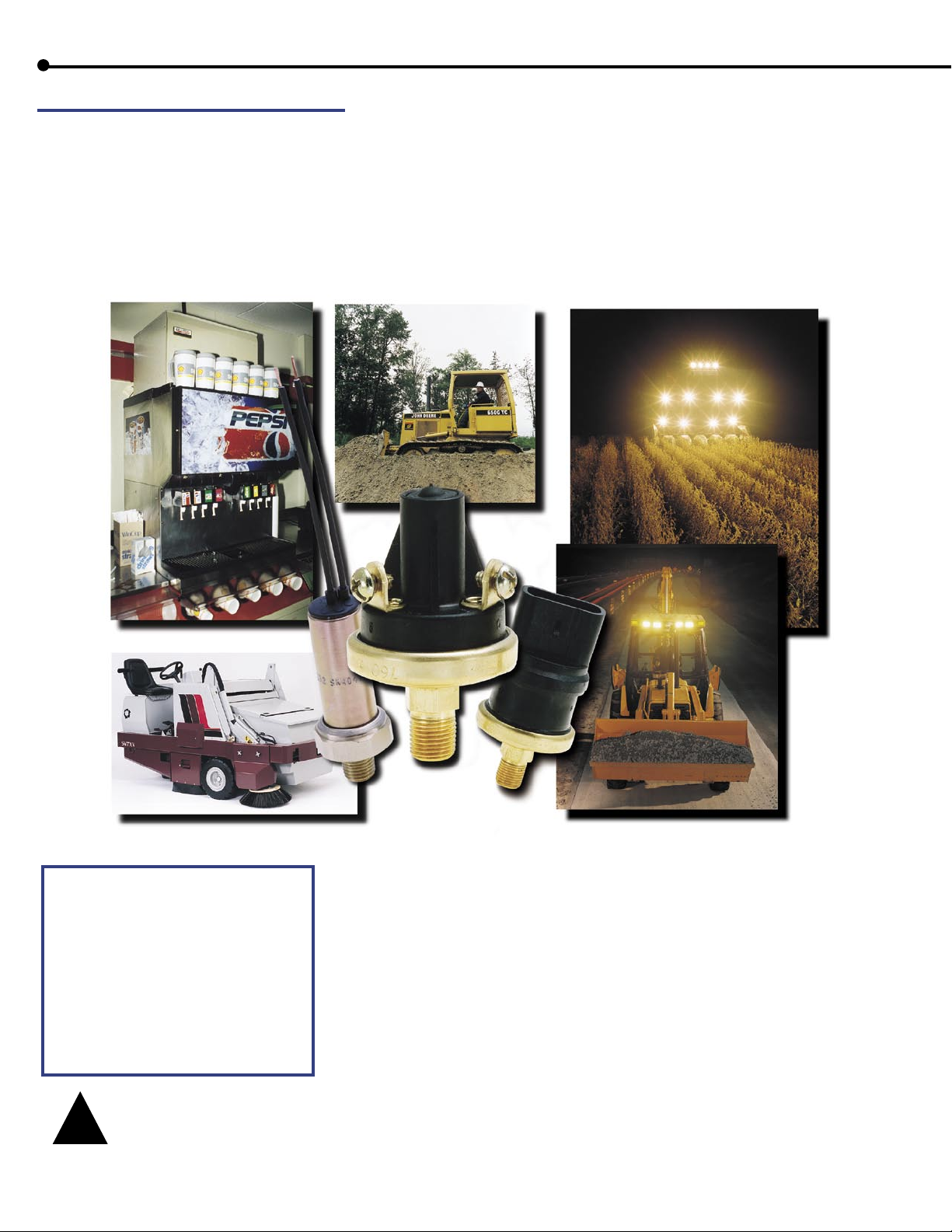
The odds are that Honeywell Sensing and Control can meet your switch demands. Designers of heavy-duty equipment have trusted
Honeywell pressure and vacuum switches for many years in applications that are constantly subjected to harsh environments…from
chemical splashes, salt water, high pressure spikes…we’ve got you covered. Our standard line is quite extensive, but if it is not exactly
what your requirements call for we can modify an existing part or create an original just for you. Honeywell has produced millions of
custom-built switches for automotive, pool and spa, powershift transmissions, anti-skid braking systems, excavator hydraulic systems,
water pump systems, and dental air compressors, to name just a few. Our highly skilled model shop, certified lab and engineering staff
can work with you through the design phase, prototype stage, all the way through to the testing phase. And if time is a crucial factor,
rapid prototyping technology can now allow us to provide you with a sample in days.
WARNING! Suitability of application is responsibility of
user. Extreme heat and vibration should be avoided at
mounting points such as on top of an engine over a hot
manifold. (MAX operation temp 250° F). Always install by
using a wrench on the hex base. Torquing at any other part
of the switch voids the warranty or may cause malfunction.
A Polyimide film diaphragm is utilized in the pressure switch
and is not recommended for use with water. However,
a Teflon diaphragm is available for water applications.
Compatibility with the brass or steel external pressure switch
material is the responsibility of the user.
For maximum operating pressures see appropriate switch
family specifications.
Contact Honeywell Engineering whenever use of switch or
fluid compatibility is questioned.
WARNING
!
PERSONAL INJURY
DO NOT USE these products as safety or emergency stop devices, or in any other application where failure of the product could
result in personal injury. Failure to comply with these instructions could result in death or serious injury.
CONTENTS
• Ultra Duty Pressure Switches 10-400 psi . . . . . . . . . . . . . . . . . . . . . . . . . . . . . . . . . . p.3
• Extended Duty Pressure Switches 0.5-150 psi . . . . . . . . . . . . . . . . . . . . . . . . . . . . . . . p.4
• Extended Duty Vacuum Switches1.1-22” Hg . . . . . . . . . . . . . . . . . . . . . . . . . . . . . . . . p.6
• Extended Duty Piston Switches 200-1000 psi . . . . . . . . . . . . . . . . . . . . . . . . . . . . . . . p.7
• Factory Set Variable Differential Pressure & Vacuum Switches 2-70 psi & 2-22” Hg . . . p.8
• High Pressure Environmentally Sealed Extreme-Duty Switches 35-3000 psi . . . . . . . . . p.9
2
Set Points from 10-400 psi
5000 Series Ultra Duty Pressure Switch
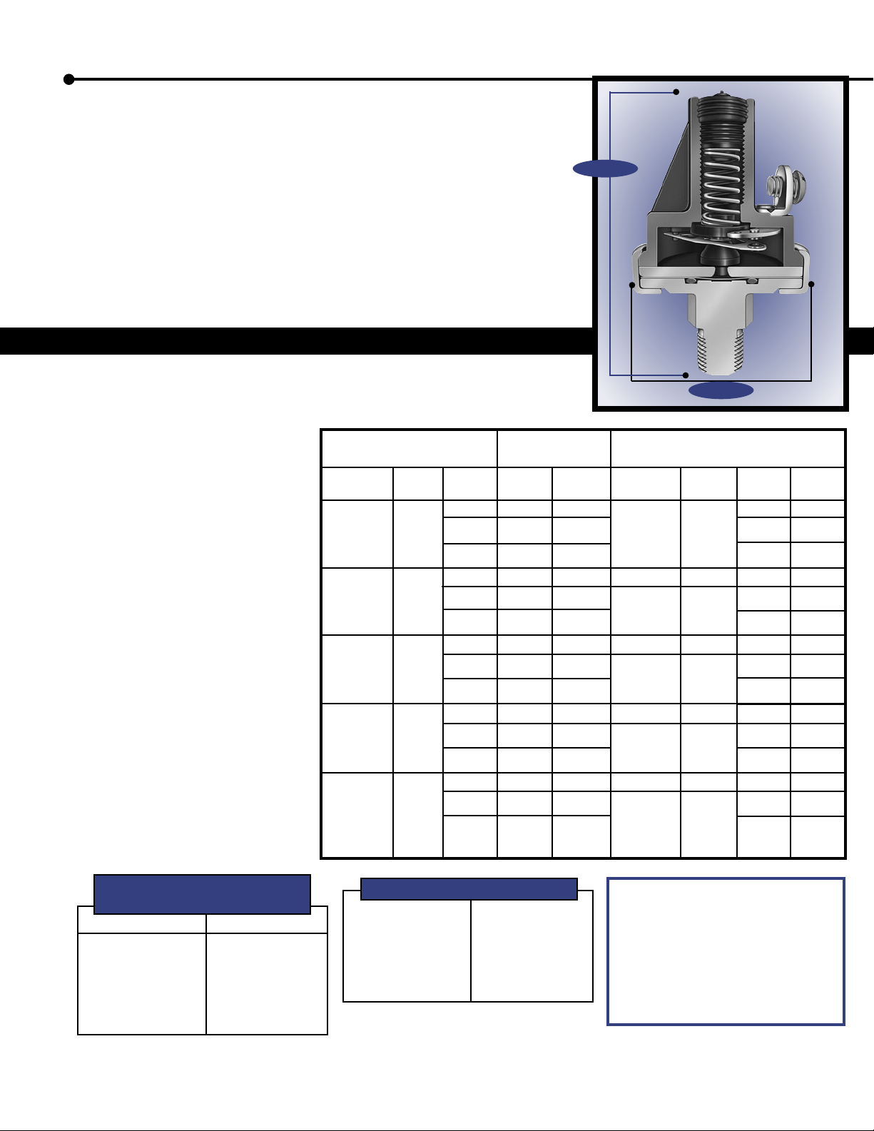
Honeywell Sensing and Control has designed a high pressure/low set point
pressure switch for applications that see sudden pressure spikes and high
system pressures that can result in early switch failures. This series has been
strengthened to prevent cracking of the base with plated steel and screw
machined components in a 3-piece design. Modifications to the effective
area of the pressure cavity and size of the diaphragm button and diaphragm
o-ring are what makes the switch capable of handling sudden pressure
transients and high system pressures that are common in applications such as
braking, transmission and hydraulic systems.
The switch’s physical appearance is similar to our 5000 Series switches with a
height of only 2.3” (approx) and a diameter of 1.47”. In comparison to our
5000 Series Switch the burst rating has significantly increased from 1250 psi
to over 4000 psi on the new design.
Specifications
Type: Direct action blade contact
Contacts: Silver alloy, gold plated
Set Point Range: 10-400 PSI
Operating Pressure: 500 PSI
Proof Pressure: 2000 PSI
Burst Pressure: 4000 PSI
Base: Plated Steel — Screw Machined
3-piece construction
Diaphragm: Polymide Film
Connector: 1/8-27 NPT Male Thread
Temperature Range: -40°F to +250°F
Terminals: #8-32 screws, 1/4” blade,
280 Series Metripack
Circuitry: SPST-N.O., N.C., SPDT
Cover: Glass Reinforced Polyester
Options: Base connector sizes, wire
leads, N.O./N.O. dual circuit and
N.C./N.C. dual circuit.
Ratings:
Resistive: 15 AMP- 6 VDC
8 AMP- 12 VDC
4 AMP- 24 VDC
Inductive: 1 AMP- 120 VAC
0.5 AMP- 240 VAC
5000 Series Ultra Duty 2 Terminals Metri-Pack Integral Connector
Pressure Switches (See Note 1)
Contact Factory Circuitry Screw Blade Contact Factory Circuitry Part #
Setting Set At Part # Part # Setting Set At
N.O. 83298 83313 N.O. 83328
DC* 83300 83315 DC* 83330
±4 psi
N.O. 83301 83316 N.O. 83331
35-75 PSI 60 PSI
DC* 83303 83318 DC* 83333
N.O. 83304 83319 85 PSI N.O. 83334
75-150 PSI 100 PSI
DC* 83306 83321 DC* 83336
N.O. 83307 83322 N.O. 83337
150-250 PSI 200 PSI
DC* 83309 83324 DC* 83339
N.O. 83310 83325 N.O. 83340
250-400 PSI 300 PSI
DC* 83312 83327 DC* 83342
10-35 PSI 20 PSI
± 6 psi
±10 psi
± 15 psi ± 10 psi
± 20 psi ± 15 psi
N.C. 83299 83314
N.C. 83302 83317
N.C. 83305 83320
N.C. 83308 83323
N.C. 83311 83326
2.3” REF.
1.47” REF.
N.C. 83329
10-30 PSI 20 PSI
± 4 psi
N.C. 83332
30-65 PSI 45 PSI
± 5 psi
N.C. 83335
65-125 PSI
± 7 psi
N.C. 83338
125-200 PSI 165 PSI
N.C. 83341
200-400 PSI 300 PSI
Approximate Dead Band
Standard Switches
Contact Setting
10-35 PSI
35-75 PSI
75-150 PSI
150-250 PSI
250-400 PSI
Dead Band
15-25 PSI
25-35 PSI
40-60 PSI
50-70 PSI
80-100 PSI
Metri-Pack Switches
10-30 PSI
30-65 PSI
65-125 PSI
125-200 PSI
200-400 PSI
3
20-35 PSI
35-55 PSI
60-85 PSI
85-115 PSI
150-200 PSI
Note 1: Mating connector for N.O. and N.C. is
Packard Part# 15300027; Mating connector for
DC is Packard Part# 12034147.
DC*- The N.C. is the reference circuit for the
DC Switch; the N.O. circuit is not adjusted. The
approximate dead band between the N.C. and
N.O. circuit is shown in the charts. For applications
requiring the N.O. circuit as the reference circuit,
the N.C. circuit is not adjusted.
Set Points from 0.5 to 150 psi
5000 Series Extended Duty Pressure Switch With Direct Action Blade Contacts
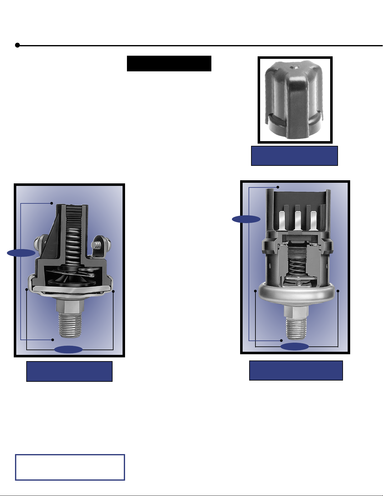
The 5000 Series switch is specifically
designed to stand up to extended duty
applications. This switch is factory set
but capable of field adjustment. It
features a Kapton diaphragm for
compatibility with a wide variety of
fluids, and various terminations
including a Metri-Pack connector that
forms a tight seal when connected.
Among the outstanding design benefits
are its durable construction, compact
size, and enhanced set point integrity.
Standard Specifications
Type: Direct action
blade contact
Contacts: Silver alloy,
gold plated
Set Point: Factory set
from 0.5 to 150 PSI
Operating Pressure:
150 PSI for 0.5-24 PSI set point range,
250 PSI for 25-150 PSI set point range
Proof Pressure: 500 PSI
Burst Pressure: 750 PSI for 0.5-24 PSI
set point range
1250 PSI for 25-150 PSI
set point range.
Ratings:
Resistive: 15 AMP- 6 VDC
8 AMP- 12 VDC
4 AMP- 24 VDC
Inductive: 1 AMP- 120 VAC
0.5 AMP- 240 VAC
Switch Boot P/N 79380
for Vacuum and Pressure
2.9” REF.
2.3” REF.
1.47” REF.
5000 Series Switch
with Screw Terminals
Diaphragm: Polyimide film
Temperature
Range: -40° F to + 250° F
Connector: 1/8 -27 NPT male thread
Terminals: #8-32 screws,
1/4” blade,
280 Series Metri-Pack
Circuitry: SPST-N.O., N.C.,
1 circuit adjustable dual
circuit, or 2 circuits
adjustable dual circuit.
Also available are
N.O./N.O. dual circuit
and N.C./N.C. dual circuit.
Base: Plated Steel
Cover: Glass reinforced polyester
Options: Brass, plastic or stainless
steel base; various base
connector thread sizes;
wire leads (potted & sealed).
1.47” REF.
5000 Series Switch
with Metri-Pack Terminal
NOTE: OPERATING MEDIA (PRESSURE SWITCH)
The pressure switch is designed to operate with air,
motor oils, transmission oils, jet fuels and other similar
hydrocarbon media.
4

5000 Series Pressure Switch With Standard Terminal
Dual Circuit
One circuit adjustable
Part Number
Screw Blade
78711
76071
76579
76580
76072
76073
76074
76075
Both circuits adjustable2
(Mates with Packard
P/N 12034147)
Contact
Setting
3-4 PSI
±0.5
5-10 PSI
±1
11-24 PSI
±2
25-46 PSI
±3
47-76 PSI
+5/-2
+7/-2
+9/-2
+10/-2
78712
76076
76587
76588
76077
76078
76079
76080
Dual Circuit
3
Part
Number
77047
77048
77049
77050
77051
77052
77053
77054
Contact
Setting
0.5-1 PSI
±0.3
1.1-3 PSI
±0
.5
3.1-7 PSI
±1
8-13 PSI
±2
14-24 PSI
±3
25-50 PSI
±5
51-90 PSI
±7
91-150PSI
±10
Factory
Set At
1 PSI
2 PSI
4 PSI
10 PSI
15 PSI
35 PSI
60 PSI
100 PSI
Circuitry
N.O.
N.C.
N.O.
N.C.
N.O.
N.C.
N.O.
N.C.
N.O.
N.C.
N.O.
N.C.
N.O.
N.C.
N.O.
N.C.
Single Circuit
1 Terminal
Part Number
Screw
78630
78634
78142
78149
78143
78150
78144
78151
78145
78152
78146
78153
78147
78154
78148
78155
78631
78635
78399
78406
78400
78407
78401
78408
78402
78409
78403
78410
78404
78411
78405
78412
Blade
Single Circuit
2 Terminals
Part Number
Screw
78628
78632
76051
76061
76575
76577
76576
76578
76052
76062
76053
76063
76054
76064
76055
76065
Blade
78629
78633
76056
76066
76583
76585
76584
76586
76057
76067
76058
76068
76059
76069
76060
76070
5000 Series Pressure Switch With Metri-Pack Terminal
Dual Circuit
One circuit adjustable
(Mates with Packard
P/N 12034147)
Part Number
77038
77039
77040
77041
77042
77043
77044
77045
77046
1
77-100 PSI
101-126 PSI
127-150 PSI
Contact
Setting
1-3 PSI
±0.5
4-6 PSI
±1
7-12 PSI
±2
13-24 PSI
±3
25-46 PSI
±5
47-76 PSI
±6
77-100 PSI
±7
101-126
±9
127-150 PSI
±10
Factory
Set At
2 PSI
5 PSI
10 PSI
20 PSI
35 PSI
60 PSI
85 PSI
115 PSI
135 PSI
Single Circuit
(Mates with Packard
P/N 15300027)
Circuitry
N.O.
N.C.
N.O.
N.C.
N.O.
N.C.
N.O.
N.C.
N.O.
N.C.
N.O.
N.C.
N.O.
N.C.
N.O.
N.C.
N.O.
N.C.
Part Number
77029
77020
77030
77021
77031
77022
77032
77023
77033
77024
77034
77025
77035
77026
77036
77027
77037
77028
1
Setting
3-4 PSI
±0.5
5-8 PSI
±1
9-24 PSI
±2
25-50 PSI
±3
51-90 PSI
+5/-2
91-150 PSI
+8/-2
Notes:
1. The N.C. circuit is the reference
circuit for the dual circuit switch;
the normally open circuit is not
adjusted. The expected dead band
between the N.C. & N.O. circuit
is shown in the chart below. For
applications requiring the normally
open circuit as the reference circuit
the N.C. circuit is not adjusted.
2. Switch may be adjusted so that:
A. N.C. circuit opens before N.O.
circuit closes.
B. N.C. and N.O. circuit have same
set point.
C. N.O. circuit closes before the
N.C. circuit opens. (There is no
dead band and both circuits are on
for a brief period of time.)
3. The tolerances given in the table
are applicable to a switch adjusted
so that the N.O. circuit closes
before the N.C. circuit opens and
applies to the N.C. circuit. The
N.O. set point and tolerances are
such that a minimum overlap of 1
PSI exists during which both circuits
are on.
Dual Circuit
Both circuits adjustable
3
Part NumberContact
Screw
76081
76582
76082
76083
76084
76085
2
Blade
76086
76590
76087
76088
76089
76090
Note 1: Expected Dead Band (Higher than N.C. circuit)
Contact
Setting
0.5-3 PSI
4-7 PSI
8-13 PSI
14-24 PSI
25-50 PSI
51-90 PSI
91-150 PSI
Dead Band
1.5 PSI
2.5 PSI
3.5 PSI
8 PSI
15 PSI
23 PSI
40 PSI
5

Set Points from 1.1” to 22” Hg
5000 Series Extended Duty Vacuum Switches With Direct Action Blade Contacts
The 5000 Series switch is specifically
designed to stand up to extended duty
applications. This switch is factory
set. It features a fluorosilicone rubber
diaphragm for compatibility with a
wide variety of fluids, and various
terminations including a Metri-Pack
connector that forms a tight seal when
connected. Among the outstanding
design benefits are its durable
construction, compact size, and
enhanced set point integrity.
Standard Specifications
Type: Direct action blade
contact
Contacts: Silver alloy, gold plated
Set Point: Factory set
Vacuum: 1.1 to 22” Hg
Operating
Pressure: 30” Hg vacuum max.
Burst Pressure: 150 PSI
2.3” REF.
Switch Boot P/N 79380
for Vacuum and Pressure
1.47” REF.
5000 Series Switch
with Screw Terminals
Ratings:
Resistive: 15 AMP- 6 VDC
8 AMP- 12 VDC
4 AMP- 24 VDC
Inductive: 1 AMP- 120 VAC
0.5 AMP- 240 VAC
Diaphragm: Fluorosilicone elastomer
Temperature
Range: -40° F to + 250° F
Connector: 1/8-27 NPT male thread
Terminals: #8-32 screws,
1/4” blade,
280 Series Metri-Pack
Circuitry: SPST-N.O., N.C.
Base: Brass
Cover: Glass reinforced
polyester
Options: Various base connector
thread sizes; wire leads
(potted & sealed).
5000 Series Vacuum Switch
Internally Grounded
Part Number
Contact Setting
1.1-22” Hg
Standard set points are 2”Hg(27” H2O), 4”Hg, 9”Hg, and 17”Hg
Contact Setting Tolerance
1.1-3”Hg (15-41”H2O)
4-8”Hg
9-17”Hg
18-22”Hg
Circuitry
N.O.
N.C.
±.22”Hg(3”H2O)
±1”Hg
±2”Hg
±3”Hg
Screw Blade Screw
78813
78815
78814
78816
Two Terminals
Part Number
77342
77343
Blade
77344
77345
6

Set Points from 200 to 1000 psi
5000 Series Extended Duty Piston Switches With Direct Action Blade Contacts
The 5000 Series piston switch is
specifically designed for extended duty
applications with set point requirements
2.45” REF.
1.47” REF.
5000 Series Piston Switch
with Screw Terminals
3.05” REF.
1.47” REF.
5000 Series Piston Switch
with Metri-Pack Terminal
from 200 to 1000 PSI. This switch is
factory set with various terminations
available including a Metri-Pack
connector that forms a tight seal when
connected. Among the outstanding
design benefits are its durable
construction, compact size, and
enhanced set point integrity. This switch
has a wide media compatibility making
it ideal for a number of applications.
Standard Specifications
Type: Direct action blade
contact
Contacts: Silver alloy, gold plated
Set Point: Factory set
Pressure: 200-1000 PSI
Operating
Pressure: 1000 PSI
Proof Pressure: 2000 PSI
Burst Pressure: 3000 PSI
Piston Switch
with Standard Terminal
Contact Setting
Range
200-400
±30
401-800
±60
801-1000
±90
Approximate
Differential
30-100
40-125
50-180
Circuitry
N.O.
N.C.
N.O.
N.C.
N.O.
N.C.
Piston Switch
with Metri-Pack Terminal
Contact Setting
Range
200-350
±30
351-500
±45
501-750
±60
* Note: The N.C. circuit is the reference circuit for the dual circuit switch; the normally open circuit
is not adjusted. For applications requiring the normally open circuit as the reference circuit, the
N.C. circuit is not adjusted.
Specify: 1. Set point 2. Actuate on increasing or decreasing pressure 3. SPST N.O. or N.C. SPDT.
Approximate
Differential
30-100
40-125
50-150
Circuitry
N.O.
N.C.
N.O.
N.C.
N.O.
N.C.
Single Circuit
Part Number
Screw
79700
79702
79704
79706
79708
79710
(Mates with Packard
P/N 15300027)
Part Number
Blade
79701
79703
79705
79707
79709
79711
Single Circuit
79718
79719
79720
79721
79722
79723
Dual Circuit *
one circuit adjustable
Part Number
Screw
79712
79714
79716
one circuit adjustable
(Mates with Packard
Part Number
Blade
79713
79715
79717
Dual Circuit *
P/N 12034147)
79724
79725
79726
Ratings:
Resistive: 15 AMP- 6 VDC
8 AMP- 12 VDC
4 AMP- 24 VDC
Inductive: 1 AMP- 120 VAC
0.5 AMP- 240 VAC
Standard Seal: Nitrile
(others available)
Temperature
Range: -40° F to + 250° F
Connector: 1/2-20 UNF
(o-ring fitting)
Terminals: #8-32 screws,
1/4” blade,
280 Series Metri-Pack
Circuitry: SPST-N.O., N.C., D.C.
Base: Steel
Cover: Glass reinforced
polyester
Options: Brass, stainless steel
base; o-ring fittings;
seal for brake fluid;
wire leads (potted and
sealed); boot p/n
79380 (see photo on
page 4.)
7

Set Points from 2 to 70 psi and 2” to 22” Hg
Series III Factory Set Variable Differential Pressure & Vacuum Switches With Snap Action Contacts
The Series III switch is a customizable
switch built per customer specifications.
It features a non-ferrous chamber
and excellent set point integrity at
extreme temperatures. The exclusive
snap switch features: Low-contact
resistance, wiping action, fast transfer
time, gold over silver contacts, and
an adjustable differential. It’s been
thoroughly tested for shock and
vibration resistance and is particularly
valuable in applications where
hysteresis, fast transfer time, and low
contact resistance are vital.
Pressure Switch
Standard Specifications
Type: Snap action switch
Set Point: Factory set
Pressure: 1-70 PSI
Operating
Pressure: 200 PSI
Proof Pressure: 350 PSI
Burst Pressure: 500 PSI
Ratings:
Resistive: 15 AMP- 6 VDC
8 AMP- 12 VDC
4 AMP- 24 VDC
Inductive: 1 AMP- 120 VAC
0.5 AMP- 240 VAC
Dry circuits
Diaphragm: Beryllium copper
Temperature
Range: -40° F to + 250° F
Connector: 1/8 -27 PTF SAE short
male thread
Terminals: 8” Wire leads-18 ga.
Circuitry: SPST-N.O. or N.C.,
SPDT
Base: Brass
Housing: Die cast zinc
Options: Silver contacts,
silver soldered base
Terminations: Wire leads with wide
selection of Cannon,
Packard, AMP, and
others available
Connectors: 1/4” and 3/8” PTF
SAE short; 1/2-20
UNF (o-ring fitting);
3/8-24 UNF (3/16”
tube); 7/16-24 UNF
(1/4” tube); and metric
2.5” REF.
1.69” REF.
Series III
Pressure Switch
(Vacuum Switch Similar)
Series III pressure and vacuum switches are custom built
switches designed to customer specifications therefore
minimum ship quantitities are required and are not
available off-the-shelf.
Pressure Switch/Factory Set
Reference #
120000
120001
120002
120003
120004
Set Point Range
2-4 PSI
4-12 PSI
12-24 PSI
24-40 PSI
40-70 PSI
Differential
1-1.5 PSI
2-6 PSI
8-12 PSI
10-18 PSI
15-20 PSI
Vacuum Switch/Factory Set
Reference #
120005
120006
120007
120008
Specify:1. Set Point
2. Actuate on increasing or decreasing pressure
3. SPST N.O. or N.C., SPDT
Set Point Range
15-36” H2O
2-6” Hg
6-12” Hg
12-22” Hg
Differential
4-12” H2O
0.4-1” Hg
0.4-1” Hg
0.6-1.5” Hg
Vacuum Switch
Standard Specifications
Type: Snap action switch
Set Point: Factory set
Vacuum: 2 to 22” Hg
15 to 36” H2O
Operating
Pressure: 200 PSI
Proof Pressure: 350 PSI
Burst Pressure: 500 PSI
Ratings:
Resistive: 15 AMP- 6 VDC
8 AMP- 12 VDC
4 AMP- 24 VDC
Inductive: 1 AMP- 120 VAC
0.5 AMP- 240 VAC
Dry circuits
Diaphragm: Silicone rubber
Temperature
Range: -40° F to + 250° F
Connector: 1/8 -27 PTF SAE
short male thread
Terminals: 8” Wire leads-18 ga.
Circuitry: SPST-N.O. or N.C., SPDT
Base: Brass
Housing: Die cast zinc
Options: Silver contacts, silver
soldered base,
fluorosilicone rubber
diaphragm
Terminations: Wire leads with wide
selection of Cannon,
Packard, AMP, and others
available
Connectors: 1/4” and 3/8” PTF SAE
short; 1/2-20 UNF
(o-ring fitting);
3/8-24 UNF (3/16” tube);
7/16-24 UNF (1/4” tube);
and Metric
8

Set Points from 35 to 3000 psi
Series V High Pressure Environmentally Sealed, Extreme-Duty Switches With Snap Action Contacts
The Series V switch is a high pressure
switch with set points up to 3000 PSI and
is built to exact customer specifications.
Excellent set point integrity at extreme
temperatures and wide fluid compatibility
make this switch ideal for extreme duty
applications. And, under all operating
conditions, it boasts an excellent response
time. Like the Series III, the Series V
exclusive snap switch has an adjustable
differential, low contact resistance, wiping
action, fast transfer time, and gold over
silver contacts. This switch is beneficial
where hysteresis, fast transfer time, and low
contact resistance are vital.
Standard Specifications
Type: Snap action switch
Set Point: Factory set
Pressure: 35-300 PSI (elastomeric
diaphragm)
100-3000 PSI (steel
piston)
Operating
Pressure: Diaphragm 300 PSI
Piston 3000 PSI
Proof: Diaphragm 500 PSI
Piston 5000 PSI
Burst: Diaphragm 2000 PSI
Piston 10000 PSI
Ratings:
Resistive: 15 AMP- 6 VDC
8 AMP- 12 VDC
4 AMP- 24 VDC
Inductive: 1 AMP- 120 VAC
0.5 AMP- 240 VAC
Dry circuits
Temperature
Range: -40°F to +250°F
Connector: Diaphragm 1/8-27 PTF
SAE short male thread
Piston: 3/4-16 UNF (o-ring fitting)
Terminals: 8” Wire leads-18 ga.
Circuitry: SPST-N.O. or N.C., SPDT
Base: Plated steel
Housing: Plated steel
Options: Silver contacts
Terminations: Wide selection of
Cannon, Packard, AMP,
and others available
Connectors: 1/2-20 UNF (o-ring fitting);
9/16-18 UNF (o-ring
fitting);
M14x1.5 (o-ring fitting);
Others available
upon request.
3.19” REF. 3.34” REF.
1.187” REF.
Diaphragm Type
Diaphragm Type
Reference Number
26900
26901
26902
26903
Set Point Range
35-50 PSI
50-100 PSI
100-200 PSI
200-300 PSI
Differential
10-15 PSI
10-15 PSI
10-15 PSI
10-20 PSI
Piston Type
Reference Number
26904
26905
26906
26907
26908
26909
26910
26911
26912
26913
26914
26915
26916
Set Point Range
100-150 PSI
150-250 PSI
250-500 PSI
500-750 PSI
750-1000 PSI
1000-1250 PSI
1250-1500 PSI
1500-1750 PSI
1750-2000 PSI
2000-2250 PSI
2250-2500 PSI
2500-2750 PSI
2750-3000 PSI
Differential
35-50 PSI
50-75 PSI
75-100 PSI
100-150 PSI
150-300 PSI
175-350 PSI
175-360 PSI
220-370 PSI
230-380 PSI
250-390 PSI
355-400 PSI
370-420 PSI
385-450 PSI
9
1.187” REF.
Piston Type
Specify:1. Set Point
2. Actuate on increasing
or decreasing pressure
3. SPST N.O. or N.C.,
SPDT
Series V pressure and vacuum switches
are custom built switches designed
to customer specifications therefore
minimum ship quantitities are required
and are not available off-the-shelf.

Switch Definitions and Terminology
Pressure/Vacuum Switch - A device
that senses a change in pressure/
vacuum and opens or closes an
electrical circuit when the set point is
reached.
Set Point - The pre-determined
pressure/vacuum value that is required
to open or close the electrical contacts
in the switch.
Electrical Contacts - The elements
in the switch that electrically respond
to the media applied to the actuator.
Snap action contacts with a
“self-cleaning” wiping effect are used
in Series III and Series V switches.
Direct action blade contacts are used
in the 5000 Series.
Pressure Switch Actuator - The
member in the switch which receives
the media and ultimately strokes the
electrical contacts to open or close at
the designated set point. The actuator
in the Series III is a beryllium copper
or silicone rubber diaphragm. An
elastomeric diaphragm or piston
actuator is used in the Series V.
The 5000 Series uses a polyimide
film diaphragm.
Normally Open (SPST-N.O.) - A
normally open switch does not conduct
an electrical signal until the actuator
is moved by the media causing the
contacts to close.
Normally Closed (SPST-N.C.)
- A normally closed switch conducts
electricity until the actuator is moved
by the media causing the contacts to
open.
Dual Circuit (SPDT) - A normally
open and normally closed circuit are
contained in a switch.
Dual Circuit (N.O./N.O.) - Switch
contains two normally open circuits.
System Pressure/Vacuum - This is
the normal pressure/vacuum that would
be present at the switch actuator. This
value is important in order to apply
the proper switch configuration. Even
though the set point may be relatively
low, the system pressure would continue
to be applied to the switch actuator in
most cases.
Proof Pressure - This specification is
the maximum over-pressure condition
that the switch can have for a specified
period of time and still maintain set
point integrity.
Burst Pressure - This specification is
the maximum over pressure condition
that the switch can withstand without
experiencing leakage.
Dry Circuit Load - Typically this would
be a very low electrical load associated
with microprocessors when the open
circuit voltage is .03V or less and the
current is 40mA or less.
Resistive Load - A load in which the
voltage is in phase with the current.
Inductive Load - A load in which the
voltage leads the current.
Motor Load - The load of a motor at
rated horsepower and speed.
Capacitive Load - A load which the
current leads the voltage.
Differential - The difference between
opening (actuation) pressure and the
closing (de-actuation) set points. This
is also referred to as “dead band”. For
example, a switch set at 150 PSI to
open on increasing pressure and close
at 95 PSI on decreasing pressure
would have a differential of 55 PSI
(150-95=55).
Conversion Factors
Convert
kPa
PSI
BARS
PSI
Hg”
PSI
H2O”
PSI
H2O”
Hg”
C°
F°
To
PSI
kPa
PSI
BARS
PSI
Hg”
PSI
H2O”
Hg”
H2O”
F°
C°
Multiply By
.145
6.8948
14.5
.069
.4912
2.036
.03613
27.6778
.07355
13.5962
1.8(C° +17.78)
F-32÷1.8
Dual Circuit (N.C./N.C.) - Switch
contains two normally closed circuits.
10

Honeywell's Springfield and Spring Valley, Illinois facilities manufacture a broad range of electro and electronicmechanical products that include Hobbs hour meters, pressure and vacuum switches, off-highway vehicular lighting,
transmission shifters, turn signal controls, rotary switches, and off-highway vehicular hand controls. Honeywell's customer
base is very broad including industries such as automotive, agricultural, material handling, construction, marine, medical,
heavy truck, lawn and garden, recreational, generators, compressors and aviation. Our commitment to continuous
improvement and total quality management will allow for further expansion of its product lines and customer base while
maintaining the highest standards of excellence.
MANUFACTURING
Honeywell's commitment to the customer in past years
and present is what has helped us develop our
world-class manufacturing systems. Some of the methods
by which we continuously improve products and processes
are as follows:
Six Sigma methodology is a strategy used to
accelerate improvements in our processes, products
and services, and to reduce manufacturing costs
and improve quality. It achieves this by relentlessly
focusing on eliminating waste and reducing defects
and variations.
Continuous Flow Process utilizing “Rabbit Chase”
concepts are used in the focused factories in order
to achieve the lowest total cost, defect-free product.
Single Minute Exchange of Dies (SMED method)
provides reduced time in the molding cell.
Statistical Process Control is used for measuring
critical dimensions and controlling manufacturing
processes.
Poka-Yoke method and computerized test
equipment are utilized to eliminate scrap and
rework.
Kanban cards are used to pull raw material and
piece parts through the factory.
Bar coding and electronic data interchange (EDI) are
available.
QUALITY SYSTEMS
It is the goal of Honeywell to meet customer value-needs
through continuously improved products and processes.
That is the basis by which we work to create a partnership
with our customers. Evidence of our commitment is proven
by a goal of a Shipped Product Quality Level (SPQL) of 100
ppm. We utilize Advanced Quality Planning, and a QS9000
based quality system.
11

Warranty/Remedy
Honeywell warrants goods of its manufacture as being free of
defective material and faulty workmanship. Contact your local
sales office for warranty information. If warranted goods are
returned to Honeywell during that period of coverage, Honeywell
will repair or replace without charge those items it finds
defective. The foregoing is Buyer’s sole remedy and is
in lieu of all other warranties, expressed or implied,
including those of merchantability and fitness for a
particular purpose.
While we provide application assistance, personally, through
our literature and the Honeywell web site, it is up to the customer
to determine the suitability of the product in the application.
Specifications may change at any time without notice. The
information we supply is believed to be accurate and reliable as
of this printing. However, we assume no responsibility for its use.
Sales and Service
Honeywell serves its customers through a worldwide
network of sales offices and distributors. For application
assistance, current specifications, pricing or name of the
nearest Authorized Distributor, contact your local sales
office or:
INTERNET: www.honeywell.com/hobbs
E-mail: honeywellhobbs.marketing@honeywell.com
For Honeywell pressure and vacuum switches
contact the Springfield location at
217-753-7798 or visit
www.honeywell.com/hobbs
Sensing and Control
Honeywell
P.O. Box 19424
Springfield, IL 62794-9424
USA
email: www.honeywellhobbs.marketing@honeywell.com
www.honeywell.com/hobbs
Catalog 10-1003, GLO Printed in the U.S.A.
© 2004 Honeywell International Inc. All Rights Reserved.
 Loading...