

Honeywell SV9540, SV9640 Installation Manual
SV9540; SV9640
SmartV alve™ System Controls
INSTALLATION INSTRUCTIONS
APPLICATION
The SV9540; SV9640 SmartValve™ System Controls
combine gas flow control and electronic intermittent pilot
sequencing functions into a single unit. The low voltage
igniter, flame sensor and pilot burner are supplied by the
Q3450 or Q3480 Pilot Hardware. Provides all gas ignition
safety functions by controlling gas flow, ignition source,
and a 120 Vac or 240 Vac combustion air blower. The
control also monitors the appliance airflow proving switch
and limit string to assure proper appliance operation.
Provides prepurge, postpurge, timed trial for pilot igniton,
with 100 percent shutoff and continuous retry. Diagnostic
LED indicates system status.
This control communicates directly with the ST9160
Electronic Fan Timer (EFT) in typical forced warm air
furnace applications. It also interfaces with the 208907
Terminal Board, providing compatibility with power stealing
thermostats. Or, it directly interfaces with the appropriate
power supplies and a system thermostat for additional
appliance applications. When controlled directly by a
thermostat, the control does not provide a postpurge
function, as power to the control is removed when the
thermostat call for heat ends.
The SV9540; SV9640 system is suitable for a wide range
of fan assisted combustion gas-fired appliances including
furnaces, rooftop furnaces, boilers, unit heaters, infrared
heaters, water heaters and commercial cooking appliances. The specific application of the SmartValve System
is the responsibility of the appliance manufacturer. See
Table 1 for temperature ranges and regulator types.
SPECIFICA TIONS
CA UTION
The SV9540; SV9640 provide direct replacement
only. Use the Y8610 to convert standing pilot
systems to electronic ignition systems.
Table 1. Model Number Suffix Letter Designation.
Model No.
Suffix
Letter
H0°F to 175°F
M-40°F to +175°F
P-40°F to +175°F
Ambient
Temperature Range
(-18°C to +79°C)
(-40°C to +79°C)
(-40°C to +79°C)
Pressure
Regulator Type
Slow-opening
Standard
Step-opening
Body Pattern:
SV9540: Straight through with 1/2 in. inlet and 1/2 in.
outlet; or 1/2 in. NPT inlet and 1/2 in. inverted flare
outlet.
SV9640: Straight through with 1/2 in. inlet and 1/2 in.
outlet, 1/2 in. inlet and 3/4 in. outlet, or 3/4 in. inlet
and 3/4 in. outlet.
Electrical Ratings:
System Transformer:
SV9540: 40 VA minimum NEMA rated.
SV9640: 40 VA minimum NEMA rated.
NOTE: Larger system transformer may be
Voltage and Frequency:
Output Ratings:
Current at 24 Vac:
Table 2. Thermostat Current (Run Mode); with
Prepurge Time (Factory-set):
3, 15, 30 or 45 seconds, depending on model.
Trial for Ignition:
90 seconds.
Postpurge Time (Factory-set):
5 seconds; this is not available when the SmartValve
System Control is connected directly to the thermostat.
Retry Delay:
5 minutes.
Flame Failure Response Time:
1.6 seconds maximum at 2 µA.
Capacity:
See Table 3.
Conversion:
Use conversion factors in Table 4 to convert capacities for
other gases.
required for specific applications.
24 Vac, 60 Hz; 50 Hz models available.
Igniter Load: 1.5A maximum.
Induced Draft Motor Load: 2.5A Full Load, 10A
Locked Rotor at 120 Vac; 1.75A Full Load, 5A
Locked Rotor at 240 Vac.
24V Thermostat: See Table 2.
control connected directly to thermostat.
Model 24 Vac, 60 Hz
SV9540 0.25A
SV9640 0.25A
®U.S. Registered Trademark
Copyright © 1997 Honeywell Inc. • All Rights Reserved
X-XX UL
69-1059
SV9540; SV9640 SmartValve™ SYSTEM CONTROLS
Regulation Range (Btuh);
SV9540 with 1/2 in. NPT Outlet:
Natural Gas:
Minimum: 20,000.
Maximum: 200,000.
LP Gas:
Minimum: 40,000.
Maximum: 200,000.
SV9540 with 1/2 in. Inverted Flare Outlet:
Natural Gas:
Minimum: 20,000.
Maximum: 180,000.
LP Gas:
Minimum: 40,000.
Maximum: 180,000.
SV9640 (3/4 in. x 3/4 in.):
Natural Gas:
Minimum: 30,000.
Maximum: 415,000.
LP Gas:
Minimum: 30,000.
Maximum: 415,000
Table 3. Capacity
Model
SV9540 1/2 x 1/2 NPT 150 ft3/hr (4.2 m3/hr) 20 ft3/hr (0.6 m3/hr) 200 ft3/hr (5.7 m3/hr)
SV9640 1/2 x 1/2 240 ft3/hr (6.8 m3/hr) 30 ft3/hr (0.8 m3/hr) 340 ft3/hr (9.6 m3/hr)
a
Capacity based on 1000 Btu/feet3, 0.64 specific gravity natural gas at 1 in. wc pressure drop (37.3 MJ/meter3, 0.64
specific gravity natural gas at 0.25 kPa pressure drop).
b
Capacity is reduced by 5 percent with the use of outlet screen.
c
Valves are guaranteed at only 77 percent of the rating.
Table 4. Gas Capacity Conversion Factor.
Gas
Manufactured 0.60 0.516
Mix e d 0.70 0.765
Propane 1.53 1.62
Table 5. Adapter (Flange) Part Numbers.
Inlet/Outlet
Pipe Size
3/8 in. NPT Straight 393690-1 393690-11
1/2 in. NPT Straight 393690-6 393690-16
3/4 in. NPT Straight 393690-4 393690-14
a
Flange kits include one flange, one O-ring and four
mounting screws.
b
Do not use flanges on control models with 3/4 in. inlet
and 3/4 in. outlet. On models with 1/2 in. inlet and
3/4 in. outlet, use flanges only on the 1/2 in. inlet side.
Flange
Type
Elbow 393690-2 393690-12
Elbow 393690-3 393690-13
Elbow 393690-5 393690-15
Size
(Inlet x Outlet) (in.)
1/2 NPT x 1/2
inverted flare
1/2 x 3/4 270 ft3/hr (7.6 m3/hr) 30 ft3/hr (0.8 m3/hr) 370 ft3/hr (10.5 m3/hr)
3/4 x 3/4 300 ft3/hr (8.5 m3/hr) 30 ft3/hr (0.8 m3/hr) 415 ft3/hr (11.8 m3/hr)
Specific
Gravity
Part No.
Without
Hex
Wrench
Capacity (at 1 in.
wc pressure drop
130 ft3/hr (3.7 m3/hr) 20 ft3/hr (0.6 m3/hr) 180 ft3/hr (5.1 m3/hr)
Multiply Listed
Capacity By
a,b
With Hex
Wrench
Natural-LP Gas Conversion Kits:
Natural Gas to LP:
393691 Conversion Kit.
LP to Natural Gas:
394588 Conversion Kit.
IMPORTANT
SV9540P; SV9640P CANNOT be field-converted
to LP or natural gas.
Pipe Adapters:
Angle and straight adapters available for 3/8-, 1/2- and 3/
4-in. pipe. See Table 5. Flange kits include one flange with
attached O-ring, four mounting screws, a 9/64 in. hex
wrench and instructions.
Approvals:
International Approval Services (IAS):
Design Certified C2030025.
b
of SV9540; SV9640.
a,c
Minimum
)
Regulated Capacity
Maximum
Regulated Capacity
PLANNING THE INSTALLATION
W ARNING
FIRE OR EXPLOSION HAZARD
CAN CAUSE PROPERTY DAMAGE,
SEVERE INJURY, OR DEATH
Follow these warnings exactly:
1. Plan the installation as outlined below.
2. Plan for frequent maintenance as described in
the Maintenance section.
When intermittent pilot systems are used on central
heating equipment in barns, greenhouses, and commercial
properties and on heating appliances such as commercial
cookers, agricultural equipment, industrial heating
equipment and pool heaters, heavy demands are made on
the controls. Special steps may be required to prevent
nuisance shutdowns and control failure due to frequent
cycling, severe environmental conditions related to
moisture, corrosive chemicals, dust or excessive heat.
These applications require Honeywell Home and Building
Control Engineering review; contact your Honeywell Sales
Representative for assistance.
Review the following conditions that can apply to your
specific installation and take the precautionary steps
suggested.
69-1059
2

SV9540; SV9640 SmartValve™ SYSTEM CONTROLS
Frequent Cycling
This control is designed for use on appliances that typically
cycle three to four times an hour only during the heating
season. In year-around applications with greater cycling
rates, the control can wear out more quickly. Perform a
monthly checkout.
Water or Steam Cleaning
If a control gets wet, replace it. If the appliance is likely to
be cleaned with water or steam, protect (cover) the control
and wiring from water or steam flow. Mount the control
high enough above the bottom of the cabinet so it does not
get wet during normal cleaning procedures.
High Humidity or Dripping Water
Dripping water can cause the control to fail. Never install
an appliance where water can drip on the control.
In addition, high ambient humidity can cause the control to
corrode and fail. If the appliance is in a humid atmosphere,
make sure air circulation around the control is adequate to
prevent condensation. Also, regularly check out the
system.
Corrosive Chemicals
Corrosive chemicals can attack the control, eventually
causing a failure. If chemicals are used for routine
cleaning, avoid contact with the control. Where chemicals
are suspended in air, as in some industrial or agricultural
applications, protect the control with an enclosure.
Dust or Grease Accumulation
Heavy accumulations of dust or grease can cause the
control to malfunction. Where dust or grease can be
a problem, provide covers for the control to limit
contamination.
Heat
Excessively high temperatures can damage the control.
Make sure the maximum ambient temperature at the
control does not exceed the rating of the control. If the
appliance operates at very high temperatures, use
insulation, shielding, and air circulation, as necessary, to
protect the control. Proper insulation or shielding should be
provided by the appliance manufacturer; verify proper air
circulation is maintained when the appliance is installed.
INST ALLA TION
When Installing this Product…
1. Read these instructions carefully. Failure to follow
them could damage the product or cause a hazardous condition.
2. Check the ratings given in the instructions and on
the product to make sure the product is suitable for
your application.
3. Installer must be a trained, experienced service
technician.
4. After installation is complete, check out product
operation as provided in these instructions.
WARNING
FIRE OR EXPLOSION HAZARD
CAN CAUSE PROPERTY DAMAGE,
SEVERE INJURY OR DEATH
Follow these warnings exactly:
1. Disconnect power supply before wiring to
prevent electrical shock or equipment
damage.
2. To avoid dangerous accumulation of fuel gas,
turn off gas supply at the appliance service
valve before starting installation, and perform
Gas Leak Test after completion of installation.
3. Do not bend pilot tubing at ignition system
control or pilot burner after compression fitting
is tightened, or gas leakage at the connection
can result.
4. Always install a sediment trap in gas supply
line to prevent contamination of ignition
system control.
WARNING
LINE VOLTAGE
CAN CAUSE PROPERTY DAMAGE,
SEVERE INJURY OR DEATH.
Never apply a jumper across or short any of the
terminals in the SV9540; SV9640 wiring harness.
This can damage the system transformer or the
control.
Follow the appliance manufacturer instructions if available;
otherwise, use these instructions as a guide.
Converting Ignition System Control
from Natural Gas to LP Gas Application
(or LP Gas to Natural Gas Application)
WARNING
FIRE OR EXPLOSION HAZARD
CAN CAUSE PROPERTY DAMAGE,
SEVERE INJURY OR DEATH
Do NOT attempt to convert step-opening models
(SV9540P/SV9542P; SV9640P/SV9642P). Always
change the main and pilot burner orifices when
converting from natural to LP gas or from LP to
natural gas. Follow appliance manufacturer
specifications and instructions carefully to assure
proper appliance conversion.
Ignition system controls are factory-set for natural (and
manufactured) or LP gas. Do not attempt to use an ignition
system control set for natural (manufactured) gas on LP
gas, or an ignition system control set for LP gas on natural
(manufactured) gas.
Ignition system controls with standard or slow opening
regulators (SV9540M,H; SV9640M,H) can be converted
from one gas to the other with a conversion kit (ordered
separately). Order part no. 393691 to convert from natural
(manufactured) to LP gas; order part no. 394588 to
convert from LP to natural (manufactured) gas.
IMPORTANT
Ignition system controls with step-opening
regulators (SV9540P; SV9640P) CANNOT be
field-converted to LP or natural gas.
69-10593
SV9540; SV9640 SmartValve™ SYSTEM CONTROLS
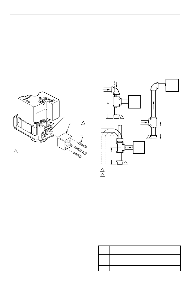
Install Adapters To Control
If adapters are being installed on the control, mount them
as follows:
Flanges
1. Choose the appropriate flange for your application.
2. Remove the seal over the ignition system control
inlet or outlet.
3. Make sure that the O-ring is fitted in the groove of
the flange. If the O-ring is not attached or missing,
do not use the flange.
4. With the O-ring facing the ignition system control,
align the screw holes on the ignition system control
with the holes in the flange. Insert and tighten the
screws provided with the flange. See Fig. 1. Tighten
the screws to 25 inch-pounds of torque to provide a
gas-tight seal.
VALVE OUTLET
1
FLANGE
9/64 INCH
HEX
SCREWS
(4)
1 DO NOT USE FLANGES ON 3/4 IN. INLET
AND 3/4 IN. OUTLET MODELS, AND ON
THE 3/4 IN. OUTLET SIDE OF 1/2 IN.
INLET AND 3/4 IN. OUTLET MODELS.
Fig. 1. Firmly fasten flange to valve,
but do not overtighten screws.
Bushings
1. Remove the seal over the ignition system control
inlet or outlet.
2. Apply a moderate amount of good quality pipe
compound to the bushing, leaving two end threads
bare. On an LP installation, use compound resistant
to LP gas. Do not use Teflon tape.
3. Insert the bushing in the ignition system control and
carefully thread the pipe into the bushing until tight.
Complete the instructions below for installing the piping,
installing the control, connecting the pilot tubing and wiring.
Make sure the leak test you perform on the control after
completing the installation includes leak testing the
adapters and screws. If you use a wrench on the valve
after the flanges are installed, use the wrench only on the
flange, not on the control. See Fig. 5.
Location
The SV9540; SV9640 are mounted in the appliance
vestibule on the gas manifold.
IMPORTANT
These ignition system controls are shipped with
protective seals over the inlet and outlet tappings.
Do not remove the seals until ready to connect
the piping.
M12168
Install Piping to Control
All piping must comply with local codes and ordinances or
with the National Fuel Gas Code (ANSI Z223.1 NFPA No.
54), whichever applies. Tubing installation must comply
with approved standards and practices.
1. Use new, properly reamed pipe free from chips. If
tubing is used, make sure the ends are square,
deburred and clean. All tubing bends must be
smooth and without deformation.
2. Run pipe or tubing to the ignition system control. If
tubing is used, obtain a tube-to-pipe coupling to
connect the tubing to the ignition system control.
3. Install a sediment trap in the supply line to the
ignition system control. See Fig. 2.
DROP
HORIZONTAL
3 IN.
(76 MM)
MINIMUM
HORIZONTAL
RISER
3 IN.
(76 MM)
MINIMUM
ALL BENDS IN METALLIC TUBING SHOULD BE SMOOTH.
1
CAUTION: SHUT OFF THE MAIN GAS SUPPLY BEFORE REMOVING
2
THE END CAP TO PREVENT GAS FROM FILLING THE WORK AREA.
TEST FOR GAS LEAKAGE WHEN INSTALLATION IS COMPLETE.
PIPED
GAS
SUPPLY
IGNITION
SYSTEM
CONTROL
2
DROP
TUBING
1
GAS
SUPPLY
2
IGNITION
SYSTEM
CONTROL
2
Fig. 2. Sediment trap installation.
Install Control
1. This ignition system control can be mounted 0 to
90 degrees in any direction, including vertically,
from the upright position of the ignition system
control switch.
2. Mount the control so the gas flow is in the direction
of the arrow on the bottom of the ignition system
control.
3. Thread the pipe the amount shown in Table 6 for
insertion into ignition system control or adapters. Do
not thread pipe too far. Valve distortion or malfunction can result if the pipe is inserted too deeply.
RISER
PIPED
GAS
SUPPLY
3 IN.
(76 MM)
MINIMUM
IGNITION
SYSTEM
CONTROL
M3343A
Table 6. NPT Pipe Thread Length (in.).
Pipe
Size
Thread Pipe
this Amount
Maximum Depth Pipe can
be Inserted into Control
3/8 9/16 3/8
1/2 3/4 1/2
3/4 13/16 3/4
69-1059
4
SV9540; SV9640 SmartValve™ SYSTEM CONTROLS
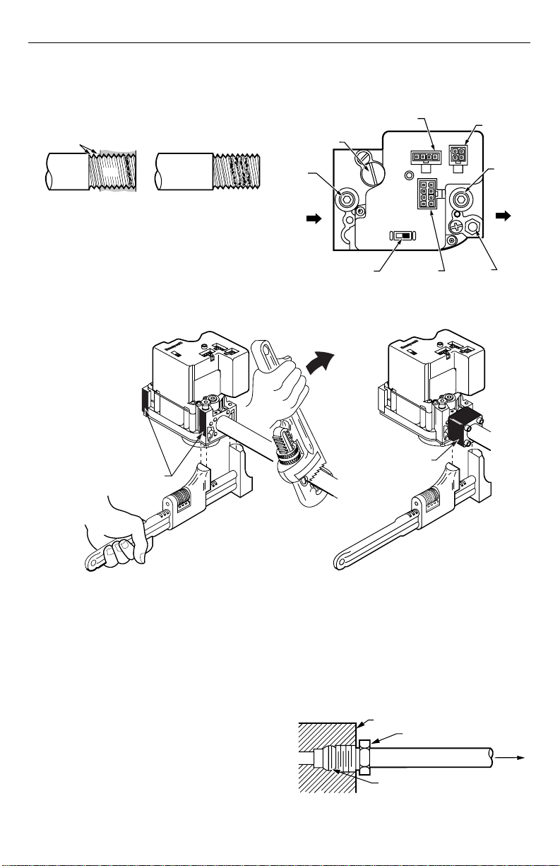
4. Apply a moderate amount of good quality pipe
compound (do not use Teflon tape) only to the pipe,
leaving two end threads bare. On LP installations,
use a compound resistant to LP gas. See Fig. 3.
TWO
IMPERFECT
THREADS
THREAD PIPE THE AMOUNT
SHOWN IN TABLE FOR INSERTION
INTO IGNITION SYSTEM CONTROL
IGNITION
SYSTEM
CONTROL
PIPE
APPLY A MODERATE AMOUNT OF
PIPE COMPOUND ONLY TO PIPE
(LEAVE TWO END THREADS BARE).
M3344
Fig. 3. Use moderate amount of pipe compound.
5. Remove the seals over the ignition system control
inlet and outlet, if necessary.
6. Connect the pipe to the ignition system control inlet
and outlet. Use a wrench on the square ends of the
ignition system control. If a flange is used, place the
WHEN FLANGE IS NOT USED
APPLY WRENCH FROM TOP OR
BOTTOM OF IGNITION SYSTEM
CONTROL TO EITHER SHADED AREA
wrench on the flange rather than on the ignition
system control. Refer to Fig. 4 and 5.
IGNITER
PRESSURE REGULATOR
ADJUSTMENT (UNDER
CAP SCREW)
INLET
PRESSURE
TAP
INLET
IGNITION SYSTEM
CONTROL SWITCH
CONNECTOR
OFF
CONTROLS
CONNECTOR
C2
C1
ON
Fig. 4. Top view of ignition system control.
WHEN FLANGE IS USED
APPLY WRENCH
TO FLANGE ONLY
C3
PILOT
OUTLET
LINE VOL TAGE
CONNECTOR
OUTLET
PRESSURE
TAP
OUTLET
M15045
Fig. 5. Proper use of wrench on ignition system control with and without flanges.
Connect Pilot Gas Tubing
1. Cut tubing to the desired length and bend as
necessary for routing to the pilot burner. Do not
make sharp bends or deform the tubing. Do not
bend the tubing at the ignition system control after
the compression nut is tightened, because this can
result in gas leakage at the connection.
2. Square off and remove burrs from the end of
the tubing.
3. Unscrew the brass compression fitting from the pilot
outlet (Fig. 4). Slip the fitting over the tubing and
slide out of the way. See Fig. 6
4. Push the tubing into the pilot gas tapping on the
outlet end of the control until it bottoms. While
holding the tubing all the way in, slide the fitting into
place and engage the threads—turn until finger tight.
Then tighten one more turn with a wrench. Do not
overtighten.
M12169
5. Connect the other end of the tubing to the pilot
burner according to the instructions supplied with
Q3450/Q3480.
NOTE: The pilot tubing provides the SmartValve System
flame sense current path. Make sure the
connections are clean and tight for proper
operation.
IGNITION SYSTEM CONTROL
TIGHTEN NUT ONE TURN
BEYOND FINGER TIGHT
FITTING BREAKS OFF AND CLINCHES
TUBING AS NUT IS TIGHTENED
TO PILOT
BURNER
M3346
Fig. 6. Always use new compression fitting.
69-10595
 Loading...