

Page 1

SV9501/SV9502/SV9601/SV9602
TM
SmartValve
APPLICATION
The Honeywell TRADELINE® SmartValveTM System
Controls provide easy field replacement of a wide range
of SV9500, SV9501, SV9502 and SV9602 SmartValve
System models. Gas appliance manufacturers use these
models in many types of gas fired heating appliances
including central furnaces, residential boilers, rooftop
furnaces, commercial cooking appliances, and unit
heaters. These TRADELINE® controls provide
intermittent pilot gas ignition sequencing, pilot flame
sensing, and both pilot and main gas control functions in
a single control. They are directly compatible with the
Q3450 or Q3480 Intermittent Pilot burners used with the
original controls on the appliance.
The TRADELINE® SV9501 and SV9502 SmartValve
models are replacement controls only for the SV9500,
SV9501, and SV9502 models noted in Table 5. Do not
use these controls to replace other types of intermittent
pilot or direct ignition controls. Do not use these controls
to replace SmartValve
Replacement table. The controls might fit, but the gas
flow control functions might not be compatible with the
appliance.
The TRADELINE® SV9602 SmartValve
replacement controls only for the SV9500P, SV9501P,
SV9502P, SV9600P and SV9601P models noted in Table
5. The SV9602 is a prepurge, step-opening model.
IMPORTANT
Do not use these controls to replace
SmartValve
replacement table.
Prepurge is nominally 30 seconds.
The step opening function provides a timed step outlet
pressure at the start of each heating cycle to allow main
burner ignition at reduced outlet pressure.
Reducer bushings are provided with the SV9602 and
SV9601 models for adapting to smaller pipe sizes.
TM
models not listed in the
TM
models not listed in the
System Control
INSTALLATION INSTRUCTIONS
IMPORTANT
Carefully determine the full Honeywell model
number of the existing control. Use Table 4 or
Table 5 to make sure the replacement control
model is suitable for replacing the original
control. If the control is not suitable, obtain the
correct TRADELINE® replacement control as
shown in Table 4 or Table 5, or contact the
appliance manufacturer for the proper
replacement control.
INSTALLATION
When Installing this Product…
1. Read this instructions carefully. Failure to follow
the instructions as written can damage the product
or cause a hazardous situation.
2. Check the relevant chart and the ratings given in
these instructions and on the specific model to
make sure the product is suitable for the
application.
3. Installer must be a trained, experienced, licensed
(if required by local ordinance) technician.
4. Use these instructions to check product operation
after completing installation.
IMPORTANT
Make sure the control being replaced is
defective. See Fig. 13 through 16 for SV9500,
SV9501, and SV9502 Sequence of Operation
and Troubleshooting procedures.
Planning the Installation
WARNING
Fire or Explosion Hazard.
Can cause severe injury, death or property
damage.
Follow these warnings exactly as written.
1. Plan the installation as outlined in this section.
2. Plan for frequent maintenance as described in
the Maintenance section of this manual.
Intermittent pilot systems used on heating equipment in
barns, greenhouses, and commercial properties, and on
heating appliances such as commercial cookers,
agricultural equipment, and pool heaters make heavy
TM
models are
TM
TM
69-1270-3
Page 2

SV9501/SV9502/SV9601/SV9602 SMARTVALVE
TM
SYSTEM CONTROL
demands on the controls. Special steps are
recommended to prevent nuisance shutdowns and control
failures due to frequent cycling, or severe environmental
conditions such as exposure to moisture, corrosive
chemicals, dust, or excessive heat. Following are the
possible causes of shutdown and the preventative
solutions.
Frequent Cycling
These controls are designed to cycle three to four times
each hour during the heating season. Year around
applications and applications with more frequent cycling
rates can wear out controls more quickly than normal
operation. Perform monthly system checks to make sure
the system operates properly.
Water or Steam Cleaning
Replace any electronic control that gets wet. If the
appliance is likely to be cleaned with water or steam,
cover the control and wiring to protect them from water or
steam flow. Mount the control high enough above the
cabinet bottom to avoid getting it wet during cleaning
procedures.
High Humidity or Dripping Water
Dripping water can cause the control to fail. Never install
an appliance where water can drip on the control. High
humidity around the control can cause the control to
corrode and fail. If the appliance is located in a humid
atmosphere, make sure the air circulation around the
control is adequate to prevent water condensing on the
control. Check the system regularly for signs of
condensation and corrosion.
Corrosive Chemicals
Corrosive chemicals can erode the control, eventually
causing a failure. If chemicals are used for routine
cleaning, make sure they do not touch the control. Where
chemicals are suspended in air, for example, in some
industrial or agricultural applications, protect the control
with an enclosure.
Dust or Grease Accumulation
Heavy accumulations of dust or grease can cause the
control to malfunction. Where dust or grease are
problems, cover the control to limit contamination.
Installation
WARNING
Fire or Explosion Hazard.
Can cause severe injury, death or property
damage.
Follow these warnings exactly as written.
1. Disconnect the power supply before wiring to
prevent electrical shock and equipment
damage.
2. Turn of the gas supply at the appliance service
valve before starting installation to avoid
dangerous accumulation of fuel gas.
3. Perform gas leak test after completing
installation.
4. Do not bend pilot tubing at ignition system
control or pilot burner after tightening the
compression fitting. Bending can cause gas
leakage at the connection.
5. Always install a sediment trap in the gas supply
line to prevent contamination of the ignition
system.
WARNING
Fire or Explosion Hazard.
Can cause severe injury, death or property
damage.
Follow this warning exactly as written.
• Always change the main and pilot burner
orifices when converting between LP and
natural gas. Follow appliance manufacturer
specifications and instructions.
CAUTION
Equipment Damage Hazard.
Improper device replacement will damage the
equipment.
The SV9501, SV9502, SV9602, and SV9601
provide direct replacement only as shown in Table
4 or Table 5 of this manual. Use the Y8610 to
convert standing pilot systems to electronic
ignition systems.
Heat
Excessively high (above 175°F [79°C]) temperatures can
damage the control. Make sure the ambient temperature
at the control does not exceed the control rating. If the
appliance operates at very high temperatures, use
insulation, shielding and proper air circulation as
necessary to protect the control. The appliance
manufacturer should provide proper insulation or
shielding. Make sure there is proper air circulation when
installing the appliance.
69-1270—3 2
CAUTION
Equipment Damage Hazard.
Can Burn Out Heat Anticipator in Thermostat.
1. Never apply a jumper across or short the
terminals in the SV9501, SV9502, SV9602, or
SV9601 connectors or appliance wiring
harnesses.
2. Never short the electric fan timer (EFT) output.
Shorting the output can damage the EFT drive
circuitry.
IMPORTANT
These ignition system controls are shipped with
protective seals over inlet and outlet tappings.
Do not remove seals until ready to connect
piping.
Follow the appliance manufacturer’s instructions if
available. Otherwise, use these instructions as a guide.
Page 3
SV9501/SV9502/SV9601/SV9602 SMARTVALVE
TM
SYSTEM CONTROL
Ignition system controls are set at the factory for natural
or LP gas. Do not attempt to use an ignition control made
for LP gas on a natural gas system. Do not attempt to use
an ignition control made for natural gas on an LP gas
system.
Ignition system controls with standard opening regulators
(SV9501M, SV9502M, and SV9601M) or slow opening
regulators (SV9501H and SV9502H) can be converted
between natural gas and LP gas.
Ignition system controls with step opening regulators (P
suffix) cannot be converted between gases.
Selecting the Valve
Make sure when replacing any SmartValveTM that you
know what valve is going in and what valve is coming out.
The SV9501 and SV9502 look slightly different from the
SV9500. The SV9500 features an ON/OFF control knob,
as shown in Fig. 1. The SV9501, SV9502, SV9602, and
SV9601 have an ON/OFF switch, as shown in Fig. 2. The
SV9501, SV9502, SV9601, and SV9602 have a
connector located at the top of the valve instead of on the
front.
The SV9501, SV9502, SV9602, and SV9601 have
identical valve body features and use the same
connectors.
NOTE: The SV9601 and the SV9602 do not have flange
mounting capability.
Use of Pipe Adapters
In some field service applications, space limitations make
it difficult or impossible to thread the gas control onto the
gas supply line. This problem can be resolved for many
installations by using a pipe adapter. Install the pipe
adapter on the end of the supply line in place of the gas
control by following the same precautions and instructions
that are used for installing the gas control. After the pipe
adapter is installed, attach the gas control to the adapter.
NOTE: Using a pipe adapter increases the overall length
of the gas control.
Install Pipe Adapter to Gas Control
Install adapter to gas control as follows:
Bushings
1. Remove seal over gas control inlet or outlet.
2. Apply moderate amount of good quality pipe com-
pound to bushing, leaving two end threads bare.
3. Insert bushing into gas control and carefully thread
pipe into the bushing until tight.
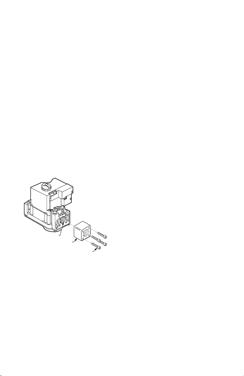
Installing Flange Adapters to Control
(If Required)
Mount any necessary adapters as follows:
Flanges
1. Choose the correct flange for the application.
2. Remove the seal over the ignition system control or
outlet.
3. Make sure the O-ring is fitted in the flange groove. If
the O-ring is not attached or is missing, do not use
the flange.
4. With the O-ring facing the ignition system control,
align the screw holes on the ignition system control
with the holes in the flange.
5. Insert the screws provided with the flange.
6. Tighten the screws firmly but do not over tighten
VALVE OUTLET
FLANGE
9/64 INCH HEX SCREWS (4)
Fig. 1. Front view of SV9500. Notice the ON/OFF
control knob.
M3342A
Location
Mount the SV9501, SV9502, SV9602, or SV9601 on the
gas manifold in the appliance.
Installing Piping to Control
IMPORTANT
Do not use Teflon® tape.
All piping must comply with local codes or ordinances or
with the National Fuel Gas Code (ANSI Z223.1 NFPA No.
54), whichever applies. Tubing installation must comply
with approved standards and practices.
1. Use new, properly reamed pipe that has no chips.
2. Make sure the ends are square, deburred, and
clean.
3. Make sure all tubing bends are smooth and without
deformation.
4. Get a tube-to-pipe coupling if necessary.
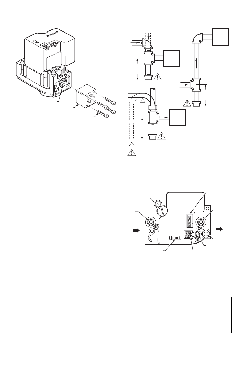
5. Run pipe or tubing to the ignition system control.
6. Install a sediment trap in the supply line to the
ignition system control as shown in Fig. 3.
3 69-1270—3
Page 4
SV9501/SV9502/SV9601/SV9602 SMARTVALVE
TM
SYSTEM CONTROL
VALVE OUTLET
M17142
Fig. 2. Front view of SV9501 or SV9502. Notice the
connectors and the ON/OFF control switch.
FLANGE
9/64 INCH HEX SCREWS (4)
Installing the Control
This ignition system can be mounted from 0 to 90 degrees
in any direction including vertically from the upright
position of the ignition system control switch.
IMPORTANT
Make sure to mount the replacement control
in the same location and orientation as the
original control.
1. Mount the control so the gas flow is in the direction
of the arrow on the bottom of the ignition system
control, as shown in Fig. 4.
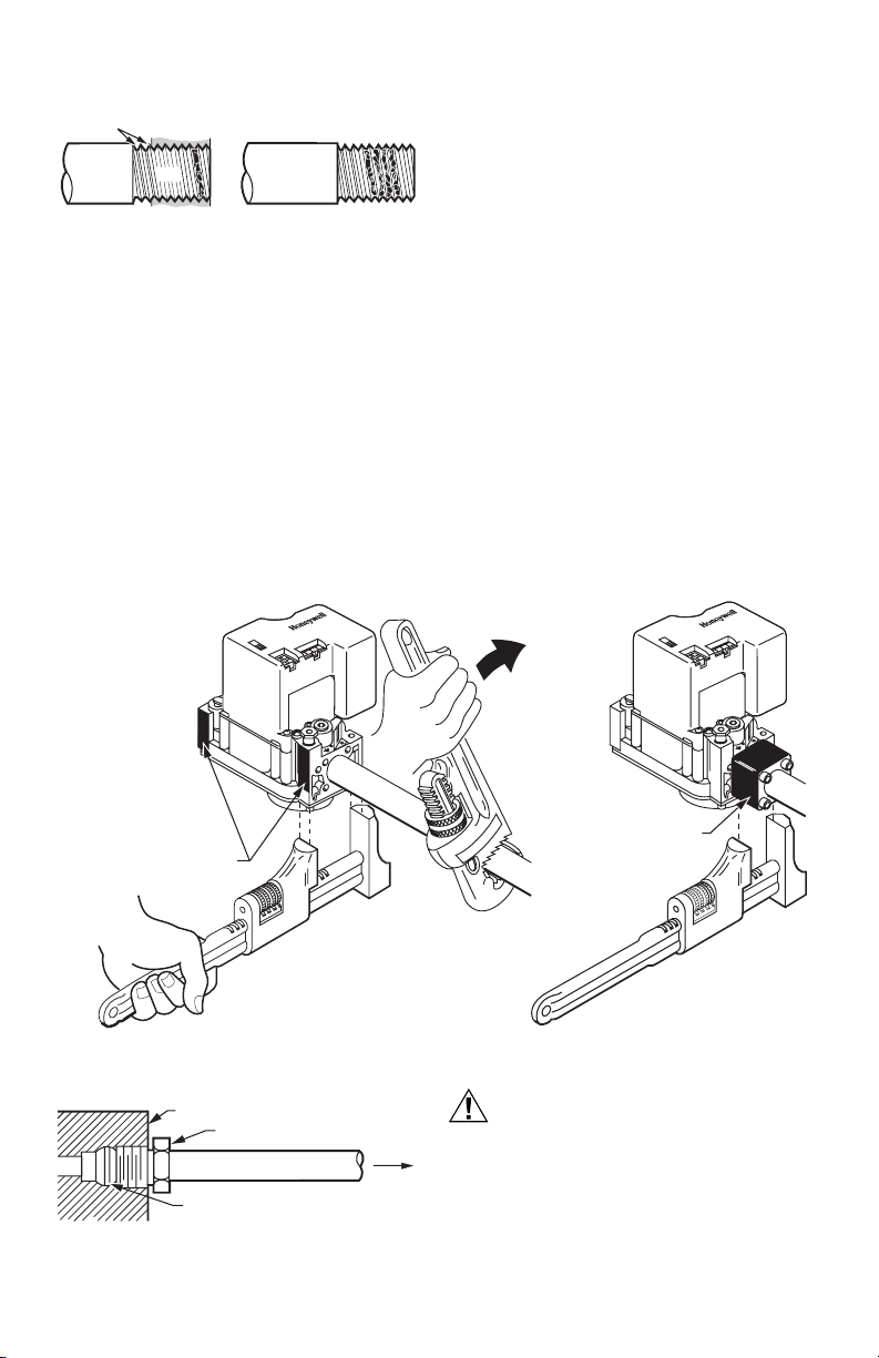
2. Apply a moderate amount of good quality pipe compound to the pipe, leaving the two end threads bare,
as shown in Fig. 5. For LP controls make sure to
use an LP resistant pipe compound.
3. Remove the seals over the ignition system control
inlet and outlet if necessary.
4. Thread the pipe the amount shown in Table 1. Do
not thread the pipe too far, because this could
cause valve distortion or malfunction.
5. Using a wrench on the square ends of the ignition
system control, connect the pipe to the ignition
system control inlet and outlet.
DROP
HORIZONTAL
3 IN.
(76 MM)
MINIMUM
HORIZONTAL
RISER
3 IN.
(76 MM)
MINIMUM
1
ALL BENDS IN METALLIC TUBING MUST BE SMOOTH.
CAUTION
Gas Leakage Hazard.
Failure to follow precautions can result in a gas-filled work area.
Shut off the main gas supply before removing end cap. Test for gas
leakage when installation is complete.
PIPED
GAS
SUPPLY
IGNITION
SYSTEM
CONTROL
DROP
TUBING
1
GAS
SUPPLY
IGNITION
SYSTEM
CONTROL
RISER
PIPED
GAS
SUPPLY
3 IN.
(76 MM)
MINIMUM
IGNITION
SYSTEM
CONTROL
M3343C
Fig. 3. Sediment trap installation.
PRESSURE REGULATOR
ADJUSTMENT (UNDER
CAP SCREW)
INLET
PRESSURE
TAP
ON
OFF
CONTROL
CONTROLS
CONNECTOR
IGNITER
INLET
IGNITION SYSTEM
CONTROL SWITCH
M7934
Fig. 4. Mount so gas flows in the
direction of the arrows.
NOTE: If the control has a flange, place the wrench on
the flange instead of on the ignition system control, as shown in Fig. 6.
IGNITER
CONNECTOR
OUTLET
PRESSURE
TAP
OUTLET
PILOT
OUTLET
PILOT ADJUSTMENT
(UNDER CAP SCREW)
Table 1. Threading the Pipe.
Maximum Depth Pipe
can be Inserted into
Control
Pipe Size
Thread Pipe
this Amount
3/8 in. 9/16 in. 3/8 in.
1/2 in. 3/4 in. 1/2 in.
3/4 in. 13/16 in. 3/4 in.
69-1270—3 4
Page 5
SV9501/SV9502/SV9601/SV9602 SMARTVALVE
TWO
IMPERFECT
THREADS
THREAD PIPE THE AMOUNT
SHOWN IN TABLE FOR INSERTION
INTO IGNITION SYSTEM CONTROL
IGNITION
SYSTEM
CONTROL
PIPE
APPLY A MODERATE AMOUNT OF
PIPE COMPOUND ONLY TO PIPE
(LEAVE TWO END THREADS BARE).
Fig. 5. Use a moderate amount of pipe compound.
Connecting the Pilot Gas Tubing
NOTE:
1. The pilot tubing provides the SmartValve
system’s flame sense current path. Make
sure the connections are clean and tight.
2. Do not make sharp bends or deform the
tubing. Do not bend tubing at the ignition
system control after the compression nut is
tightened, because this can cause gas
leakage.
1. Cut the tubing to the desired length.
2. Bend the tubing as necessary for routing to the pilot
burner.
3. Square off and debur the end of the tubing.
TM
4. Unscrew the brass compression fitting from the pilot
outlet.
5. Slip the fitting over the tubing and out of the way.
6. Push the tubing into the pilot gas outlet.
7. Tap the outlet end of the control.
8. Remove and discard the old fitting.
While holding tubing all the way in, slide the new fit-
9.
ting (included with the new SmartValve
and begin thread until finger tight as shown in Fig. 7.
10. Tighten fitting one more full turn with the wrench.
M3344
Do not overtighten.
11. Connect the other end of the tubing to the pilot
burner as described in the instructions supplied with
Q3450 or Q3480 pilot hardware.
Wiring
Follow the wiring instructions supplied by the appliance
TM
manufacturer if available. Otherwise, use the following
general instructions.
NOTE:
1. In most cases, connect the wiring by plugging
the appliance wiring harness connector into
the SmartValve
sion harness if necessary.
2. Where the general instructions are different
from the appliance manufacturer ’s instructions, use the appliance manufacturer’s
instructions.
TM
. Use the supplied exten-
SYSTEM CONTROL
TM
) into place
WHEN FLANGE IS NOT USED
APPLY WRENCH FROM TOP OR
BOTTOM OF IGNITION SYSTEM
CONTROL TO EITHER SHADED AREA
Fig. 6. Proper use of wrench on ignition system control with and without flanges.
IGNITION SYSTEM CONTROL
TIGHTEN NUT ONE TURN
BEYOND FINGER TIGHT
FITTING BREAKS OFF AND CLINCHES
TUBING AS NUT IS TIGHTENED
Fig. 7. Tighten new fitting and nut.
Always use a new compression fitting.
TO PILOT
BURNER
M3346
WHEN FLANGE IS USED
APPLY WRENCH
TO FLANGE ONLY
CAUTION
Equipment Damage Hazard.
Electrostatic discharge can short equipment
circuitry.
Disconnect the power supply before making wiring
connections.
IMPORTANT
All wiring must comply with applicable electrical
codes and ordinances.
M7928
5 69-1270—3
Page 6

SV9501/SV9502/SV9601/SV9602 SMARTVALVE
NOTE: If the wiring harness is damaged, contact the
equipment manufacturer for a replacement
harness.
1. Make sure the power rating on the ignition system
matches the available supply. The system transformer should be NEMA rated at 40 VA or larger.
2. Install a transformer, thermostat, and other controls
as required.
3. Connect the control circuit to the ignition system
control, as shown in Fig. 8 through 11.
TM
SYSTEM CONTROL
L2
PILOT BURNER GROUND
(THROUGH PILOT TUBING)
24 VOLT
COMMON
24 VOLT
HOT
EFT
OUTPUT
24 VOLT
THERMOSTAT
OR PRESSURE
SWITCH
POWER SUPPLY. PROVIDE
1
DISCONNECT MEANS AND OVERLOAD
PROTECTION AS REQUIRED.
Fig. 8. SV9501/SV9502/SV9602/SV9601 basic wiring
PILOT BURNER
GROUND
(THROUGH
PILOT TUBING)
diagram.
120/240 VAC
L1
1
POWER
SUPPLY
NEMA 40 VA
TRANSFORMER
24 VAC
THERMOSTAT
TO
ELECTRONIC FAN
TIMER (IF USED)
LIMIT
M7935C
FUSE
HUMIDIFIER
AIR CLEANER
INDUCER
MOTOR
STARTING
CAP
LO
ML
MH
CIRCULATING
FAN
W
CONNECT ONLY IF CONTINUOUS SPEED IS AVAILABLE AND USED.
1
CONNECT ONLY IF CONTINUOUS SPEED IS NOT USED.
2
CONNECT IF EAC AND HUM TERMINALS ARE AVAILABLE AND USED.
3
SOME MODELS USE MALE 1/4-INCH QUICK-CONNECTS INSTEAD
4
OF SCREW TERMINALS FOR THERMOSTAT CONNECTIONS.
2
HI
THERMOSTAT
GR
Y
3
UNUSED
3 DI
EAC N
HUM N
1 2
Z1
Z2
DELAY
SPEED
1
2
UP
OFF
Fig. 9. SV9501/SV9502/SV9602/SV9601 typical wiring connections in fan assisted warm air furnace
L1(H)
TO 115/230 VAC
POWER SUPPLY
L2(N)
115/230 VAC
TRANSFORMER
24 VAC
2
3
1
4
CX
MOTOR
C Y
N
LEADS
ST9120
NEUTRAL
CIR
C
COOL
CONT
1
G
BLWR
HEAT
X
SEC
XFMR
4
Y
W
COOLING
CONTACTOR
R
= DENOTES STANDARD TERMINAL.
NOTE:
= DENOTES OPTIONAL TERMINAL.
DENOTES LOW VOLTAGE WIRING.
DENOTES LINE VOLTAGE WIRING.
with ST9120 Electric Fan Timer.
ROLL-OUT
SWITCH
LIMIT
CONTROL
PRESSURE
SWITCH
PILOT BURNER
GROUND
(THROUGH
PILOT TUBING)
24 VOLT
COMMON
24 VOLT
HOT
EFT
OUTPUT
24 VOLT
THERMOSTAT
OR PRESSURE
SWITCH
M7937D
69-1270—3 6
Page 7

SV9501/SV9502/SV9601/SV9602 SMARTVALVE
TM
SYSTEM CONTROL
D892
VENT DAMPER
4 3 2 1
BLACK
M7936C
Fig. 10. SV9501/SV9502/SV9602/SV9601 typical wiring
CABLE AND
CONNECTOR
TO SUIT
AQUASTAT
CONTROL
ROLLOUT
RED
BLACK
COIL
SWITCH
SPILL
SWITCH
THERMOSTAT
RED
W
G
Y
CIRCULATOR PUMP
PILOT BURNER GROUND
(THROUGH PILOT TUBING)
R8285D
R
C
diagram in atmospheric boiler.
COMBUSTION
AIR BLOWER
BLACK
L1
L2
POWER SUPPLY. PROVIDE
1
DISCONNECT MEANS AND
OVERLOAD PROTECTION
AS REQUIRED.
24V THERMOSTAT
1
120 VAC
POWER SUPPLY
STARTUP AND CHECKOUT
WARNING
Fire or Explosion Hazard.
Can cause severe injury, death or property
damage.
Do not force the ignition switch on the appliance.
Do not use tools to move the ignition switch. If the
switch does not move by hand, a qualified service
technician must replace the control.
Ignition System Control Switch Settings
NOTE: The control switch only controls gas flow. It does
not control the igniter circuit.
Ignition system control switch settings are:
OFF
Prevents pilot and main gas flow through the ignition
system control. The rest of the ignition sequence occurs
normally.
ON
Allows gas to flow through the control valve. The
thermostat controls the gas flow to the pilot and main
burners.
PRESSURE
SWITCH
NC
R8222U RELAY
1
4
3
6
NO
C
C
R
Y
W
G
1
L2
L1
(HOT)
CIRCULATOR
POWER SUPPLY. PROVIDE DISCOUNNECT MEANS AND OVERLOAD
1
PROTECTION AS REQUIRED.
1
3
4
6
R8285D CONTROL CENTER
LIMIT
ROLL-OUT
SWITCH
PILOT BURNER
GROUND (THROUGH
PILOT TUBING)
24 VOLT
COMMON
24 VOLT
THERMOSTAT
OR PRESSURE
SWITCH
24 VOLT
HOT
EFT
OUTPUT
Fig. 11. SV9501/SV9502/SV9602/SV9601 typical wiring diagram in induced draft boiler application.
7 69-1270—3
M13036B
Page 8

SV9501/SV9502/SV9601/SV9602 SMARTVALVE
TM
SYSTEM CONTROL
Turning on the System
Push the switch to the ON position.
Turning on the Main Burner
Follow the instructions provided by the appliance
manufacturer or turn up the thermostat to call for heat. If
the main burner does not light, refer to the troubleshooting
table.
PROPER FLAME
ADJUSTMENT
3/8 TO 1/2 IN.
(10 TO 13 MM)
GROUND
ELECTRODE
Perform Gas Leak Test
WARNING
Fire or Explosion Hazard.
Can cause severe injury, death or property
damage.
1. Check for gas leaks with soap and water
solution every time work is done on a gas
system.
2. Stand clear of the main burner when lighting it
to prevent injury from hidden leaks that could
cause flashback.
Gas Leak Test
1. Paint the pipe connections located upstream from
the ignition system control with a rich soap and
water solution.
Bubbles indicate a gas leak.
2. If a leak is detected, tighten the pipe connections.
3. Repeat steps 1 and 2 until no leaks are detected in
that area.
4. Light the main burner.
5. With the main burner in operation, paint the pipe
joints, adapters, and control inlet and outlet with a
rich soap and water solution.
6. If a leak is detected, tighten the adapter screws,
joints, and pipe connections.
7. Repeat steps 5 and 6 until no leaks are detected.
8. Replace the part with the same model number if
any leak cannot be stopped.
Adjust the Pilot Flame
The pilot flame should envelop 3/8 in. to 1/2 in. (10 mm to
13 mm) of the tip of the flame rod, as shown in Fig. 12.
1. Remove the pilot adjustment cover screw.
2. Turn the inner adjustment screw clockwise to
decrease or counterclockwise to increase the pilot
flame.
3. After adjusting the flame, replace and tighten firmly
the cover screw to prevent gas leakage.
NOTE: Controls are provided with adjustment screws
set at the maximum pilot flow position.
FLAME ROD
HOT SURFACE
NOTE: GROUND ELECTRODE MUST NOT TOUCH FLAME
ROD (.050 IN. MINIMUM CLEARANCE). BEND GROUND
ELECTRODE IF NECESSARY. DO NOT BEND FLAME ROD.
Fig. 12. Proper flame adjustment.
IGNITER
M3350A
Check and Adjust Gas Input
and Burner Ignition
IMPORTANT
— Many replacement valves require outlet pressure
adjustment.
— Do not exceed the input rating stamped on the
appliance nameplate.
— Do not exceed the manufacturer’s
recommended burner orifice pressure for size of
orifice used.
— Make sure the primary air supply to the main
burner is properly adjusted for complete
combustion.
— Follow the appliance manufacturer’s
instructions.
If Checking Gas Input by Clocking Gas Meter
1. Make sure there is no gas flow through the meter
other than the flow to be checked.
2. Other appliances supplied by this meter must
remain off with their pilots extinguished or their gas
consumption must be deducted from the meter
reading.
3. Convert flow rate to Btuh as described in Gas
Controls Handbook, form 70-2602, and compare
the result to the Btuh input rating on the appliance
nameplate.
If Checking Gas Input with Manometer
1. Make sure gas supply is shut off at the manual
valve in the natural gas piping to an appliance or at
the tank for LP gas before removing the inlet
pressure plug.
2. Make sure the ignition system control is in OFF
position when removing the gauge and replacing
the plug.
3. Make sure the ignition system control is in OFF
position before removing the outlet pressure tap
plug and connecting the manometer (pressure
gauge).
4. Shut off the gas supply before disconnecting the
manometer and replacing the plug.
5. Repeat the gas leak test at the plug with the main
burner operating.
69-1270—3 8
Page 9

SV9501/SV9502/SV9601/SV9602 SMARTVALVE
TM
SYSTEM CONTROL
Standard Pressure Regulator (M Models),
Slow Open (H models), Step Open (P
Models)
1. Check the full rate manifold pressure listed on the
appliance nameplate. The ignition system control
outlet pressure must match the full rate pressure
listed on the nameplate. Adjust the pressure if they
do not match.
NOTE: Slow opening (H models) and step opening
(P models) may take several seconds to reach
full flow rate. M models will take 2 to 3 seconds
to reach full flow rate.
2. With the main burner ON, check the ignition system
control flow rate using the meter clocking method,
or check the pressure using a manometer
connected to the outlet pressure tap on the ignition
system control.
3. Adjust the pressure regulator to match the
appliance rating if necessary. See Table 2 and 3 for
factory set nominal outlet pressure and adjustment
range.
a. Remove the pressure regulator adjustment cap
screw.
b. Using a screwdriver, turn the inner adjustment
screw clockwise to increase or counter
clockwise to decrease gas pressure to the
burner.
c. Replace the cap screw and tighten it firmly to
prevent gas leakage.
4. If the desired outlet pressure or flow rate cannot be
achieved by adjusting the ignition system control,
check the ignition system control inlet pressure
using a manometer at the ignition system control
inlet pressure tap.
Table 2. SV9501/SV9502/SV9602/SV9601 Pressure Regulator Specification Pressures.
Factory Set Nominal Outlet
Nominal Inlet
Model
Typ e o f
Typ e
Standard,
Slow
Step NAT 5.0-7.0 1.2-1.7 0.9 0.2 3.5 0.9 None None 3-5 0.7-1.2
SV9501/SV9502 1/2 x 1/2
SV9602/SV9601 3/4 x 3/4
The maintenance program should include regular
checkout of the control as described in the Startup and
Checkout section, and the control system as described in
the application manufacturer’s literature.
Maintenance frequency must be determined individually
for each application. Some considerations follow:
• Cycling frequency. Appliances that cycle 20,000 times
NAT 5.0-7.0 1.2-1.7 — — 3.5 0.9 — — 3-5 0.7-1.2
LP 12.0-14.0 2.9-3.9 — — 10.0 2.5 — — 8-12 2-3
LP 12.0-14.0 2.9-3.9 2.2 0.2 10.0 2.5 None None 8-12 2.0-3.0
Model
annually should be checked each month.
Pressure Range
Gas
in. wc kPa in. wc kPa in. wc kPa in. wc kPa in. wc kPa
Table 3. Capacity of SV9501/SV9502/SV9602/SV9601.
Size
(Inlet x Outlet) (in.)
Step Full Rate Step Full Rate
Capacity (at 1 inch
wc pressure drop)
150 ft
300 ft
5. If the inlet pressure is in the factory specified
nominal range, as shown in Table 2 and 3, replace
the ignition system control. Otherwise, take the
necessary steps to provide proper gas pressure to
the control.
NOTE: If the burner firing rate is above the maximum
capacity as shown in Table 3, it might not be possible to deliver the desired outlet pressure. This
is an application issue, not a control failure. Take
whatever steps are necessary to correct the situation.
MAINTENANCE
WARNING
Fire or Explosion Hazard.
Can cause severe injury, death or property
damage.
Do not attempt to take the control apart or clean it.
Improper cleaning or reassembly may cause gas
leakage.
Regular preventive maintenance is important in
applications that place a heavy load on system controls.
This include applications in commercial cooking,
agricultural, and industrial industries where these
conditions often exist:
• Heavy cycling. In commercial cooking, the operation,
the equipment operates 100,000 to 200,000 cycles per
year. This can wear out a gas control in one to two
years.
• Exposure to water, dirt, chemicals, and heat can
damage the gas control and shut down the control
system.
Pressure Setting Range
Minimum Regulated
3
/hr (3.7m3/hr) 20 ft3/hr (0.6m3/hr) 200 ft3/hr 95.7m3/hr)
3
/hr (8.5m3/hr) 30 ft3/hr (0.8 m3/hr) 415 ft3/hr (11.8m3/hr)
• Intermittent use. Appliances that are used seasonally
should be checked before shutdown and before each
use.
• Consequence of unexpected shutdown. Where the
cost of an unexpected shutdown would be high, check
the system frequently.
• Dusty, wet, or corrosive environment. Since these
environments can cause the gas control to deteriorate
more rapidly, check the system frequently.
Capacity
Maximum Regulated
Capacity
9 69-1270—3
Page 10

SV9501/SV9502/SV9601/SV9602 SMARTVALVE
TM
SYSTEM CONTROL
Replace the system if any of the following conditions
occur:
• The system does not perform properly at checkout or
troubleshooting.
• The gas control switch is difficult to move.
• The gas control has operated for more than 200,000
cycles.
• The control is wet or shows signs of moisture.
SERVICE
WARNING
Fire or Explosion Hazard.
Can cause severe injury, death or property
damage.
Do not disassemble the ignition system control. It
contains no replaceable parts. Attempted
disassembly or repair can damage the ignition
system control.
CAUTION
Equipment Damage Hazard.
Can burn out heat anticipator in thermostat.
1. Do not apply a jumper across or short the
control terminals. Doing so may burn out the
heat anticipator in the thermostat or damage
the system transformer.
2. Make sure to check operation after service.
Sequence of Operation
1. Make sure the ignition system control switch is in
the ON position.
2. Follow the sequence of operation shown in Fig. 14.
If the Main Burner Does Not Come On with
Call for Heat
1. Make sure the ignition system control switch is in
the ON position.
2. Adjust the thermostat several degrees above room
temperature.
3. Make sure the appliance is receiving power. See
Fig. 15 or 16, as applicable.
INSTRUCTIONS TO THE
HOMEOWNER
WARNING
Fire or Explosion Hazard.
Can cause severe injury, death or property
damage.
Follow these warnings exactly as written.
1. Do not light the pilot flame manually. Pilot flame
lights automatically.
2. Smell around the appliance for gas. Be sure to
smell next to the floor, because LP gas is
heavier than air.
3. If you smell gas:
• Turn off the gas supply at the appliance
service valve. For LP gas systems, turn off
the gas supply at the gas tank.
• Do not light any appliances in the house.
• Do not touch any electrical switches.
• Do not use the phone.
• Leave the building, and go to a neighbor’s
phone to call your gas supplier.
• If you cannot reach your gas supplier, call the
fire department.
4. Do not force or use tools to move the ignition
system control switch. If the switch does not
operate by hand, the ignition system control
must be replaced by a qualified, licensed (if
required) service technician. Force or
attempted repair can result in fire or explosion.
5. Replace the ignition system control if it shows
any evidence of physical damage, tampering,
bent terminals, missing or broken parts,
stripped threads, or exposure to excessive
heat.
IMPORTANT
Follow the warnings in the Instructions to the
Homeowner section.
Follow the operating instructions provided by the
manufacturer of your heating appliance. The
following information assists in a typical ignition
system control application, but the specific
controls used and the procedures outlined by the
manufacturer of your appliance can be different.
Such appliances require special instructions.
Turning the Appliance ON
The pilot flame is lit automatically. If the appliance does
not turn on when the thermostat is set several degrees
above room temperature, follow these instructions:
69-1270—3 10
1. Set the thermostat to its lowest setting to reset the
safety control.
2. Disconnect all electric power to the appliance.
3. Remove the ignition system control access panel.
4. Move the ignition system control switch to OFF.
5. Wait a minimum of five minutes to clear out any
unburned gas. If you smell gas, follow step 3 in the
warning. Otherwise continue to the next step.
6. Move the ignition system control switch to ON.
7. Replace the ignition system control access panel.
8. Reconnect the power to the appliance.
9. Set the thermostat to the desired setting.
10. If the appliance still does not turn on, set the ignition
system control switch to OFF and contact a
qualified, licensed (if required) service technician.
Page 11

SV9501/SV9502/SV9601/SV9602 SMARTVALVE
TM
SYSTEM CONTROL
NOTE: The SV9502 and SV9602 have an
approximately 30-second prepurge delay before
start of Ignition Trial. Be sure to wait for prepurge
to be completed.
Turning the Appliance OFF
Vacation Shutdown
Set the thermostat to the desired temperature while you
are away.
START
SELF-CHECK
IGNITION
MAIN BURNER
OPERATION
SV9500/SV9600 SmartValve® FAMILY SEQUENCE OF OPERATION
APPLY 24V POWER TO SYSTEM
THERMOSTAT CALLS FOR HEAT
FLAME SIGNAL DETECTED
A POWERED PILOT VALVE OPENS AND IGNITER
ENERGIZES
PILOT LIGHTS, FLAME ROD SENSES FLAME
• IGNITER OFF
• MAIN VALVE OPENS
• MAIN BURNER LIGHTS
• ELECTRONIC FAN TIMER OUTPUT ENERGIZES
THERMOSTAT CALL FOR HEAT ENDS
NO
YES
YES
Complete Shutdown
1. Turn off the power to the appliance.
2. Move the ignition system control switch to OFF
without forcing it.
The appliance shuts off completely.
Follow the instructions in Instructions to the Homeowner
to resume normal operation.
OPERATING SEQUENCE
The following flowcharts describes the basic operating
sequence for the SV9500 and SV9501/SV9502/SV9602/
SV9601 controls. This information is designed to assist
field technicians to analyze normal appliance operation.
YES
NO
NO
FLAME
OUTAGE
OCCURS
DURING
RUN CYCLE
• WAIT FOR FLAME SIGNAL TO DISAPPEAR
• ELECTRONIC FAN TIMER OUTPUT ENERGIZES
• PILOT VALVE AND IGNITER REMAIN OFF
IGNITER
MISSING
OR
BROKEN
IGNITER
OPENS
NO SYSTEM RESPONSE—PILOT VALVE OFF
IGNITER STAYS ON, PILOT VALVE REMAINS OPEN
MAIN VALVE CLOSES
SV9500 POWERS IGNITER CIRCUIT
PILOT AND MAIN VALVES CLOSE, SYSTEM SHUTS DOWN
• MAIN AND PILOT VALVES CLOSE
END
• ELECTRONIC FAN TIMER OUTPUT DE-ENERGIZES
Fig. 13. SV9500/SV9600 SmartValve
M17145B
TM
System Sequence of Operation.
11 69-1270—3
Page 12

SV9501/SV9502/SV9601/SV9602 SMARTVALVE
TM
SYSTEM CONTROL
START
PREPURGE/
SYSTEM
CHECK
TRIAL
FOR
IGNITION
MAIN
BURNER
OPERATION
END
APPLY 24 VAC TO APPLIANCE
THERMOSTAT CALLS FOR HEAT
PREPURGE (SV9502/SV9602 ONLY)
YES
FLAME SIGNAL DETECTED?
INTERNAL CHECK OKAY?
• PILOT VALVE OPENS
• IGNITER POWERED
PILOT LIGHTS AND FLAME IS SENSED
DURING TRIAL FOR IGNITION?
• IGNITER OFF
• MAIN VALVE OPENS
ELECTRONIC FAN TIMER (EFT) OUTPUT ENERGIZES
FLAME SIGNAL LOST?
THERMOSTAT CALL FOR HEAT ENDS
• MAIN AND PILOT VALVES CLOSE
• EFT OUTPUT DE-ENERGIZES
IGNITER WILL TURN OFF ABOUT 30 SECONDS INTO THE TRIAL FOR IGNITION IF THE PILOT FLAME HAS NOT LIT. IT WILL TURN BACK
1
ON FOR THE FINAL 30 SECONDS OF THE 90 SECOND TRIAL FOR IGNITION. THE PILOT VALVE WILL BE ENERGIZED DURING THE
ENTIRE TRIAL FOR IGNITION. THIS IS NORMAL OPERATION FOR THIS GAS IGNITION SYSTEM.
NO
YES
1
YES
NO
• WAIT FOR FLAME SIGNAL TO DISAPPEAR.
• PILOT VALVE/IGNITER REMAIN OFF
NO
NO
• PILOT VALVE CLOSES
• IGNITER OFF
YES
• MAIN AND PILOT VALVES CLOSE
• EFT OUTPUT DE-ENERGIZES
FLAME LOST MORE THAN FIVE TIMES
IN ONE CALL FOR HEAT?
YES
THREE-SECOND FLAME
FAILURE RECYCLE DELAY
Fig. 14. SV9501/SV9502/SV9602/SV9601 SmartValveTM Sequence of Operation.
SV9501/SV9502/SV9601/SV9602 SmartValve® FAMILY SEQUENCE OF OPERATION
NO
FIVE-MINUTE
RETRY DELAY
M17144A
TROUBLESHOOTING
The attached flowcharts provide specific troubleshooting
information for the SV9500, SV9501 and SV9502/
SV9600, SV9601, SV9602 products. These charts assist
the field technician to analyze appliance operation
difficulties.
CAUTION
Equipment Damage.
Can damage connectors on wiring harness.
1. Proper troubleshooting requires measurement
of voltage and resistance with a volt/ohm meter.
2. Use proper size probes and appropriate testing
techniques to assure good test information
without damaging the control terminals,
Use the following basic troubleshooting procedure.
connectors or wiring harness.
1. Review this information carefully prior to going to
the job site.
2. Identify the specific SmartValve
SV9501, SV9502, SV9600, SV9601, SV9602).
3. Make sure the Q3450/Q3480 HSI element is good.
Disconnect the HSI element from the SmartValveTM.
4.
5. Using a multimeter, measure the HSI element room
temperature resistance. It should be less than 10
ohms.
TM
(SV9500,
69-1270—3 12
NOTE: The HSI element action for SV9501/SV9502/
TM
6. Make sure the SmartValve
SV9500/SV9600) is in the ON position (unless
directed otherwise in the Troubleshooting
flowchart).
7. Make sure the appliance call for heat function
provides proper inputs to the SmartValve
the 2X2 power connector. (Measure with voltmeter
on the ac scale.)
8. Follow the Operating Sequence and
Troubleshooting flow charts as shown in Fig. 13 and
15 for the installed SmartValve
to make sure replacement is necessary.
9. Follow the Operating Sequence and
Troubleshooting flow chart in Fig. 14 and 16 for the
replacement SV9501/SV9502/SV9601/SV9602
SmartValve
TM
.
SV9601/SV9602 is different from the HSI
element action for SV9500/SV9600. For
SV9500/SV9600, the element is on continuously
during a call for heat until shortly after the pilot
flame is detected, the main valve energizes and
the element turns off. For SV9501/SV9502/
SV9601/SV9602, the call for heat generates a
90-second “trial for pilot ignition.” If no pilot flame
is sensed, it retries after a five minute delay. The
element cycles off and back on once during the
trial for pilot ignition.
switch (knob if
TM
TM
SV9500/SV9600
through
Page 13

SV9501/SV9502/SV9601/SV9602 SMARTVALVE
TM
SYSTEM CONTROL
SV9500SV9600 SmartValve™ TROUBLESHOOTING SEQUENCE
NOTE: BEFORE TROUBLESHOOTING,
BECOME FAMILIAR WITH THE STARTUP
START
• TURN OFF GAS SUPPLY
• ASSURE SmartValve SWITCH IS IN ON POSITION
• DISCONNECT SYSTEM CONTROL HARNESS
• SET THERMOSTAT TO CALL FOR HEAT
CHECK FOR PROPER VOLTAGE AT CONTROL
HARNESS (SEE INSET A). VOLTAGE SHOULD BE
24V BETWEEN THERMOSTAT OR PRESSURE
SWITCH AND 24V COMMON, AND 24V
BETWEEN 24V COMMON AND 24V HOT.
PLUG HARNESS INTO SmartValve CONTROL.
WAIT FOR INTERNAL CHECK DELAY.
WAIT FOR PREPURGE.
IGNITER WARMS UP AND GLOWS RED
• TURN ON GAS SUPPLY
• PILOT BURNER LIGHTS
MAIN VALVE OPENS AND MAIN BURNER LIGHTS
YES
YES
YES
YES
1
AND CHECKOUT PROCEDURE. ALSO
CHECK PILOT BURNER ELEMENT FOR
RESISTANCE LESS THAN 10 OHMS WITH
ELEMENT AT ROOM TEMPERATURE.
CHECK:
• LINE VOLTAGE POWER
• LOW VOLTAGE TRANSFORMER
NO
• LIMIT CONTROLLER
• THERMOSTAT
2
• WIRING
• AIR PROVING SWITCH ON COMBUSTION AIR
BLOWER SYSTEM
• VENT DAMPER (IF USED) IS OPEN AND END
SWITCH MAKES
WITH PILOT BURNER CABLE CONNECTED, MEASURE
NO
VOLTAGE AT SmartValve HSI ELEMENT
OUTPUT (SEE INSET B) 24V NOMINAL.
REPLACE IGNITER/FLAME ROD ASSEMBLY
NO
CHECK THAT PILOT GAS IS FLOWING. WAIT TO
ASSURE PILOT GAS TUBING IS PURGED.
MEASURE VOLTAGE BETWEEN 24V HOT AND 24V
COMMON LEADS TO SmartValve CONTROL. MUST
MEASURE AT LEAST 19.5 VAC WITH IGNITER
POWERED. SEE INSET A TO IDENTIFY PROPER LEAD.
THIS CHECK MUST BE DONE WITH THE SmartValve
CONTROL CONNECTED AND IGNITER POWERED.
REPLACE IGNITER/FLAME ROD ASSEMBLY
NO
• CHECK THAT PILOT FLAME MAKES GOOD
CONTACT WITH PILOT BURNER FLAME ROD.
• CHECK FOR GOOD ELECTRICAL CONNECTION
THROUGH THE PILOT TUBING.
• IF BOTH OF THE ABOVE ARE GOOD, REPLACE
IGNITER/FLAME ROD ASSEMBLY
YES
YES
YES
INSET A
24 VOLT
THERMOSTAT
OR PRESSURE
SWITCH
24 VOLT
COMMON
CHECK FOR DAMAGED OR MISSING
TERMINALS IN CONNECTOR
INSET B
HSI
TERMINALS
NO
2
1
REPLACE SmartValve CONTROL
NO
REPLACE SmartValve CONTROL
NO
CHECK TRANSFORMER AND LINE
VOLT SUPPLY
2
END VIEW
OF CONTROL
HARNESS
CONNECTOR
EFT
OUTPUT
24 VOLT
HOT
SYSTEM IS OKAY
1
IGNITER WILL STAY ENERGIZED AS LONG
AS APPLIANCE CALL FOR HEAT IS IN PLACE.
CYCLE THERMOSTAT OFF AND BACK ON
MAIN BURNER LIGHTS
WHEN MEASURING VOLTAGE AT CONNECTIONS, USE
2
CARE TO ASSURE TERMINALS ARE NOT DAMAGED.
Fig. 15. SV9500/SV9600 troubleshooting guide.
13 69-1270—3
NO
REPLACE SmartValve CONTROL
M17146A
Page 14

SV9501/SV9502/SV9601/SV9602 SMARTVALVE
TM
SYSTEM CONTROL
SV9501/SV9502/SV9601/SV9602 SmartValve™ TROUBLESHOOTING SEQUENCE
NOTE: BEFORE TROUBLESHOOTING,
START
• TURN OFF GAS SUPPLY
• ASSURE SmartValve SWITCH IS IN ON POSITION
• DISCONNECT SYSTEM CONTROL HARNESS
• SET THERMOSTAT TO CALL FOR HEAT
CHECK FOR PROPER VOLTAGE AT CONTROL
HARNESS (SEE INSET A). VOLTAGE SHOULD BE
24V BETWEEN THERMOSTAT OR PRESSURE
SWITCH AND 24V COMMON, AND 24V
BETWEEN 24V COMMON AND 24V HOT.
PLUG HARNESS INTO SmartValve CONTROL.
WAIT FOR INTERNAL CHECK DELAY (SV9501/SV9601)
OR PREPURGE (SV9502/SV9602)
IGNITER WARMS UP AND GLOWS RED
• TURN ON GAS SUPPLY
• PILOT BURNER LIGHTS
MAIN VALVE OPENS AND MAIN BURNER LIGHTS
STEP MODELS (P
NOTE:
DESIGNATOR) WILL
TAKE SEVERAL
SECONDS TO REACH
FULL FIRING RATE.
SYSTEM IS OKAY
1
IGNITER WILL CYCLE OFF AND BACK ON ONCE DURING THE
90 SECOND IGNITION TRIAL. ALL VOLTAGE MEASUREMENTS
MUST BE TAKEN WHILE THE IGNITER IS POWERED.
YES
YES
YES
1
YES
BECOME FAMILIAR WITH THE STARTUP
AND CHECKOUT PROCEDURE. ALSO
CHECK PILOT BURNER ELEMENT FOR
RESISTANCE LESS THAN 10 OHMS WITH
ELEMENT AT ROOM TEMPERATURE.
CHECK:
• LINE VOLTAGE POWER
• LOW VOLTAGE TRANSFORMER
NO
• LIMIT CONTROLLER
2
• THERMOSTAT
• WIRING
• AIR PROVING SWITCH ON COMBUSTION AIR
BLOWER SYSTEM
• VENT DAMPER (IF USED) IS OPEN AND END
SWITCH MAKES
WITH PILOT BURNER CABLE CONNECTED, MEASURE
NO
VOLTAGE AT SmartValve HSI ELEMENT
OUTPUT (SEE INSET B) 24V NOMINAL.
REPLACE IGNITER/FLAME ROD ASSEMBLY
NO
CHECK THAT PILOT GAS IS FLOWING. WAIT TO
ASSURE PILOT GAS TUBING IS PURGED. RECYCLE
CALL FOR HEAT IF NECESSARY.
MEASURE VOLTAGE BETWEEN 24V HOT AND 24V
COMMON LEADS TO SmartValve CONTROL. MUST
MEASURE AT LEAST 19.5 VAC WITH IGNITER
POWERED. SEE INSET A TO IDENTIFY PROPER LEAD.
THIS CHECK MUST BE DONE WITH THE SmartValve
CONTROL CONNECTED AND IGNITER POWERED.
REPLACE IGNITER/FLAME ROD ASSEMBLY
NO
• CHECK THAT PILOT FLAME MAKES GOOD
CONTACT WITH PILOT BURNER FLAME ROD.
• CHECK FOR GOOD ELECTRICAL CONNECTION
THROUGH THE PILOT TUBING.
• IF BOTH OF THE ABOVE ARE GOOD, REPLACE
IGNITER/FLAME ROD ASSEMBLY
CYCLE THERMOSTAT OFF AND BACK ON
MAIN BURNER LIGHTS
YES
YES
YES
WHEN MEASURING VOLTAGE AT CONNECTIONS, USE
2
CARE TO ASSURE TERMINALS ARE NOT DAMAGED.
METER ELEMENT MUST BE CONNECTED.
3
NO
2
1
NO
NO
2
NO
INSET A
24 VOLT
THERMOSTAT
OR PRESSURE
SWITCH
24 VOLT
COMMON
CHECK FOR DAMAGED OR MISSING
TERMINALS IN CONNECTOR
INSET B
HSI
TERMINALS
REPLACE SmartValve CONTROL
REPLACE SmartValve CONTROL
CHECK TRANSFORMER AND LINE
VOLT SUPPLY
REPLACE SmartValve CONTROL
END VIEW
OF CONTROL
HARNESS
CONNECTOR
EFT
OUTPUT
24 VOLT
HOT
M17143B
3
Fig. 16. SV9501/SV9502/SV9601/SV9602 SmartValveTM Troubleshooting Sequence.
69-1270—3 14
Page 15

SV9501/SV9502/SV9601/SV9602 SMARTVALVE
TM
SYSTEM CONTROL
Table 4. Replacement chart for SV9500, SV9501, and SV9502.
Pressure Regulator
Order Number
Inlet/Outlet
Size
SV9502H2522 1/2 in. x 1/2 in. 3.5 0.87 Slow 15 sec. Natural
SV9501M2528 Standard None SV9500M2603
SV9501M8129 3.4 Fast SV9500M8600
SV9601M4571 3/4 in. x 3/4 in. 3.5 Standard
a
Regulator setting in replacement control differs from original. Adjust to rated pressure as necessary for optimum
performance.
b
Shipped by Honeywell as LP gas only; may have been converted to natural gas. Use Natural to LP gas conversion kit
(included) if necessary. Follow instructions in conversion kit.
c
Requires vent fitting (part no. 392877, order separately).
d
Requires 3/4 in. straight flange (part no. 393690-14, order separately).
e
Replacement control includes prepurge time not included with original control.
Setting
Type of
Opening
Prepurge
Time
Typ e o f
Gas Replacesin. wc kPa
SV9500H2609
SV9500H2617
SV9500H2724
SV9500H3607
SV9500H3615
SV9501H2409
SV9501H2417
SV9501H2425
SV9501H3415
SV9501H3423
SV9502H1706
SV9502H2522
SV9502H2704
SV9500M2629
SV9500M2637
SV9500M2645
SV9500M2652
SV9500M2674
SV9500M2682
SV9500M2686
SV9500M2690b
SV9500M2736
SV9500M2835
SV9500M3601
SV9500M3619
SV9500M3635
SV9500M6604
SV9501M2031
SV9501M2049
SV9501M2056
SV9501M2064
SV9501M2239
SV9501M2528
SV9501M2700
SV9501M2718
SV9501M2726
SV9501M2734
SV9501M2742
SV9500M8618
SV9500M8659
SV9500M8667
SV9500M8808
SV9501M8103
SV9501M8111
SV9501M8129
SV9501M2080
SV9601M4167
SV9601M3003
SV9601M4225
a,e
a,e
e
a,d,e
b,d,e
a,e
e
b,e
a,d,e
b,d,e
a,d
d
b
a,c
a
a
b,d
b
b,d
a
a
a,c
b
b
b
b
b
15 69-1270—3
Page 16

SV9501/SV9502/SV9601/SV9602 SMARTVALVE
TM
SYSTEM CONTROL
Table 5. SV9602 Replacement Chart.
Pressure Regulator
Order Number
Inlet/Outlet
Size
SV9602P4816 3/4 in. x 3/4 in. 3.5 0.7 Step 30 Sec.
SV9602P4824 2.5
SV9602P4832 10 2.5 LP
SV9602P4840 1.4
a
Regulator setting in replacement control differs from original. Adjust to rated pressure as necessary for optimum per-
formance.
b
Requires reducer accessory (included).
c
Replacement control includes prepurge time not included with original control.
d
These models were field convertible to LP gas. If the appliance has been converted to LP gas, use SV9602P4832 as
the replacement.
e
These models were field convertible to natural gas. If the appliance has been converted to natural gas, use
SV9602P4824 as the replacement.
Setting
Type of
Opening
Prepurge
Time
30 sec.
Typ e o f
Gas Replacesin. wc kPa
Natural
SV9500P2600
SV9500P2634
SV9500P2642
SV9501P2004
SV9501P2053
SV9502P2101
SV9600P4612
SV9600P4620
SV9600P4646
SV9601P4107
SV9602P4105
SV9602P4816
SV9501P2087
SV9502P2127
SV9601P4172
SV9602P4121
SV9602P4824
SV9500P2618
SV9500P2659
SV9501P2020
SV9501P2046
SV9502P2119
SV9502P2135
SV9601P4149
SV9601P4164
SV9602P4113
SV9602P4139,e
SV9602P4832
SV9600P4604
SV9600P4638
SV9600P4840
SV9601P4115
b,c
b,c
a,b,c
b,c
a,b,c
b
c
a,c
c
c
b,c,d
b,d
c,d
d
b,c
b,c
b,c,e
b,c
b
b,e
c
d,e
c
c
c
Automation and Control Solutions
Honeywell International Inc. Honeywell Limited-Honeywell Limitée
1985 Douglas Drive North 35 Dynamic Drive
Golden Valley, MN 55422 Toronto, Ontario M1V 4Z9
customer.honeywell.com
® U.S. Registered Trademark
© 2006 Honeywell International Inc.
69-1270—3 M.S. Rev. 08-06
 Loading...