

Page 1
SuperPro
SuperPro
SuperProSuperPro
Distribution Panel
Users Guide
CSSPUGV1 11/04 Rev. A
Page 2

Congratulations on your purchase of a SuperPro Distribution Panel. Your Distribution Panel seamlessly
combines both external services and internal signals to give you complete control over which signals or services
are used in any location of your home or office.
External Services – External Services are those services that originate outside your home. The three most
common services are telephone service, TV service (this may be antenna, cable or Satellite TV) and, in certain
locations, high-speed Internet service.
Internal Signals – Internal Signals are those signals generated inside the home. Examples of Internal Signals
include movies from a DVD player or VCR, pictures from a security camera at the front gate or by the swimming
pool, music from your CD player or radio, or MP3 files from your computer. Another example of Internal signals
is a print command sent from the laptop computer in the kitchen to the computer and printer in the home office.
Your Distribution Panel collects all these types of services and signals and allows you to control where they go.
If you decide to move your home office or add another computer, your Distribution Panel will allow you to quickly
and conveniently reroute the desired services and signals to the new locations. In addition, built in expansion
slots give you peace of mind in knowing that when new services or products become available, you can add
them to your Distribution Panel.
This Users Guide contains information about your Distribution Panel, its benefits, and the ways in which you can
control, change or add to your Distribution Panel.
Benefits of a Structured Wiring System
If we compare today’s home to those of the previous decade, we see many differences. One of the biggest
changes we find is the amount of electronics, and the types of services that are available. Today’s homes
have satellite dishes, multiple computers, VCR’s, TV’s and stereo equipment along with services like the
Internet that have brought information to us in ways we could not have imagined.
These new products and services bring the need to to manage and control them. For instance, which rooms
in your home or office receive telephone line 1 and which ones receive line 2? Which rooms do you want to
have access to the Internet? What about controlling access to offensive or mature web pages? Which room
will you be able to watch Satellite TV in? If you move your home office, can you reroute the telephone line or
high-speed Internet line connected to your computer, or will you have to call the service provider and wait for
them to schedule a house call?
The benefit of a Structured Wiring System is that it allows you to manage signal distribution in your home
and make changes as your needs change. In addition, installing telephone, data and coax lines in all the
rooms of your home now saves you the time and money of trying to add wiring to your home later.
Components of a Structured Wiring System
There are four main components in a Structured Wiring System.
• The Distribution Panel
• The Wiring and Multi-Media Cable and Wire
• The Receptacles and Multi-Media Outlets
• System Options
Distribution Panels
The Distribution Panel acts as the “brain” of your Structured Wiring System. It collects all the incoming
services and signals and routes them to the desired locations. The SuperPro Distribution panel provides you
with the highest level of control and customization. These panels were designed to allow you, the
homeowner, to make simple changes to your system, such as activating phone and/or TV outlets in your
home, or even disconnecting or moving the signals around in the home. The design also allows your
installer to make quick and easy upgrades to your system.
The features that make up the system will vary from home to home depending on the services used. A
SuperPro Distribution Panel includes the following features and functions.
-2-
Page 3
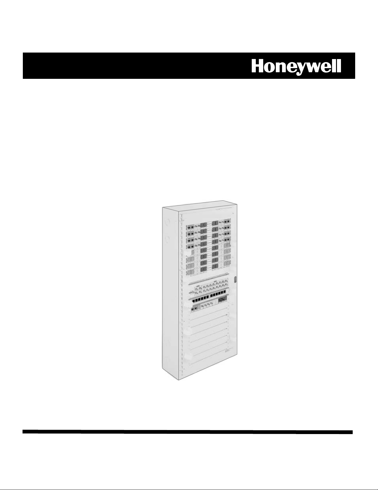
Zones
The zone or patching area is where the telephone, data
and coax wiring connect to the distribution panel. Each
zone represents a location such as master bedroom,
kids room, guest room, office, entertainment room,
kitchen, etc. In addition, each zone has a space for a
label, which is used to identify the room the zone
represents. The wiring coming from the room connects
to the rear of the zone area. Telephone and coax patch
cords are used to “patch” signals from the telephone
and coax distribution hubs to the zone area.
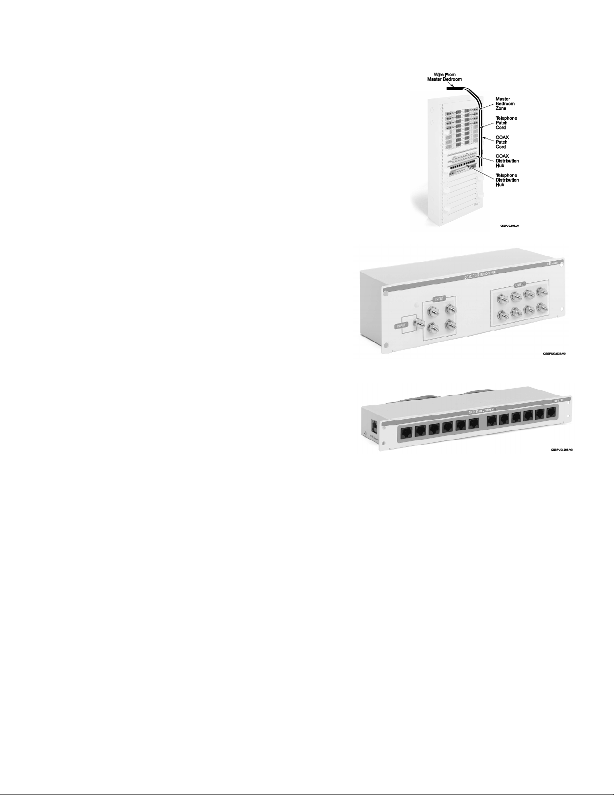
Coax Distribution Hub
The Coax Hub is used to distribute TV, Cable TV
and Satellite TV signals to multiple locations
throughout the house. In addition, the Coax Hub
can distribute modulated signals from VCR’s,
DVD’s, cameras, and even computers to multiple
locations throughout the house. The Coax Hubs
used in the SuperPro Distribution Panel include
built in signal amplification (this keeps your picture
clear and strong) and surge suppression.
Telephone Distribution Hub
The Telephone Distribution Hub is used to
distribute both voice (telephone) and data (fax
machines and computers) signals. The Telephone
Distribution Hub provided with the SuperPro
Distribution Panel includes an Amphenol connector
(this provides a connection point for upgraded
telephone systems), Surge Suppression and a built
in RJ31X port for connection to a Security system.
Each Telephone Distribution Hub can distribute
four voice or data lines to 11 locations.
Expansion Slots
Expansion slots provide room for adding additional components to your Distribution Panel, either at the
time of installation, or at a later date. Optional Modules include high-speed Internet access, computer
networking, video distribution, satellite TV, home automation, distributed home audio, etc.
Wiring and Multi-Media Cable
One of the most important components of a Structured Wiring System is the wiring. For example, having
a high-speed Internet modem will do you no good if the wire can’t process the information fast enough.
When it comes to your wiring, you need to ask two questions. How much information can my wire
handle (known as bandwidth) and how fast can it handle it (known as through-put)?
Receptacles and Multi-Media Outlets
The telephone, data, TV and Multi-Media outlets are where you plug in your phones, computers TV’s and
other electronics. Your Structured Wiring System will probably consist of a variety of receptacles. These
receptacles may have 1,2,3,4 or 6 connection points on them. In addition, these receptacles can be
custom configured to provide the type of connectivity you need in each room. They are installed at
convenient locations throughout the home. A common Multi-Media outlet would be configured as
follows:
-3-
Page 4

1. Two RJ45 telecom ports (accept standard telephone jack
inserts) used for single or multiple line telephones,
dedicated fax lines, dedicated modem lines, or data.
2. Two fiber optic jacks (optional). Used for hooking
computers together for high-speed communications, phone
lines, and TV video signals.
3. Two RG6 coax TV jacks (“F” connectors) used for video
(cable TV, antenna, satellite, cable modem, and internal
video).
Safety Features of Your Distribution Panel
Testing Phone Signal and Surge Suppression
Your SuperPro Distribution Panel provides surge suppression for both telephone and coax signals and
can withstand most of the daily surges and spikes. The surge suppression board contains resetable
transorbs, which will reset after a spike or surge. However, if your home receives an unusually large
spike, or is struck directly by lighting, the surge suppression board may blow. If the spike or surge is
strong enough to blow the transorb, then you will need to replace it.
If your phones are working following a lighting storm or power surge, the transorbs have reset
themselves. If your phones are not working the following steps should be followed to determine if the
transorbs have blown.
1. Locate a standard telephone (one that does
not require power).
2. Locate the Service Input Hub on your
Distribution Panel
3. On the Service Input Hub of your
Distribution Panel there are two telephone
connections. A short telephone patch cord
that is plugged into one of these
connections is connected to the Telephone
Distribution Hub. Unplug the short
telephone patch cord from the telephone
connection on the Service Input hub and
plug in your standard telephone.
5. If a dial tone is present the transorbs have
blown and the surge suppression board on
your Telephone Distribution Hub requires
replacement (part # TPSSB, Quantity of 2).
6. If no dial tone is present, you will need to
contact your local telephone company.
Note: Ask the telephone company to walk you through
a “dial-tone test” at the Demarc box first. If the
telephone company determines that the problem
is the wiring inside your home, they may charge
you a fee to fix it. Performing the “dial-tone test”
at the Demarc box will confirm whether the
problem is within the house wiring or not.
Only an authorized Installer should perform surge suppression board replacements.
-4-
Page 5

How Signals Flow Through a Distribution Panel
Understanding how signals flow through your Structured Wiring System will help you perform basic functions
like rerouting signals or adding additional points of service. The following is a basic overview of how signals
enter and flow through your home.
1. Telephone and TV signals enter your
home at a box called the Demarcation
Box.
2. Once these signals and services are
connected to the Demarcation Box, a
Multi-Media cable is used to connect
the Demarcation box to the Distribution
Panel. This is referred to as the
Demarcation run.
3. With the Demarcation Run connected at
the distribution panel, we can now
connect the Wiring and Multi-Media
cable running to the receptacles in each
room, creating the roadway for signals
to travel.
4. At the receptacle location, we use
telephone and TV patch cords to
connect from the receptacles to the
equipment in the room.
-5-
Page 6

Telephone Signal Management
One of the Distribution Hubs on your SuperPro Distribution
Panel is the Telephone Distribution Hub (labeled as TP
Distribution Hub). This hub can distribute up to four
telephone lines to 11 locations. The accompanying diagram
shows how signals flow through the Telephone Distribution
Hub.
1. Your installer connected the incoming telephone lines to
the two telephone connections on the Service Input Hub
(this connection was made on the back side of the
Service Input Hub). Lines 1 and 2 are connected to the
second telephone connection. Line 3, which will be used
as a dedicated line for a computer or fax machine, is
connected to the first telephone connection.
2. A short patch cord is used to patch lines 1 and 2 to the
Telephone Distribution Hub. The Telephone Distribution
Hub acts as a splitter and connects the signals that have
been patched into port one (in this case lines 1 and 2),
are available as outputs on ports 2 – 11.
3. Using longer patch cords, lines 1 and 2 are routed
betweenthe Telephone Distribution Hub and the Zones on
the upper portion of the Distribution Panel.
Separating Multiple Lines at the Room Location
The Line Breakout Box (part # LBO1) provides an easy way
to separate and access up to four individual phone lines at
any Multi-Media Outlet or a standard telephone outlet
location.
The LBO1 can be added anytime, and can be attached
directly to the Multi-Media or Telephone outlet by replacing
the bottom screw in the receptacle with a double-headed
screw (supplied with the LBO1) and hanging the LBO1 from
the Receptacle.
In addition, by using a longer patch cord, the LBO1 can be
placed on the desktop or any other convenient location.
Once the LBO1 is installed on the bottom of the receptacle, a
short patch cord (supplied with the LBO1) is used to connect
from the telephone port on the receptacle to the L1-L4 Input
on the LBO1.
The LBO1 separates the 4 incoming telephone lines and
sends them to the 4 ports on the bottom of the LBO1. As you
can see in the diagram below, the port on the far right is for
line one (this port also can be used for two line telephones),
the second port from the right is line 2, the third port from the
right is line 3, and the port on the left is for line 4. You will
also notice a pass thru port on the left hand side. This allows
all four lines to pass to another device or to another LBO1
Line Breakout Box.
-6-
Page 7

TV Signal Management
1. Your installer ran a RG6 coax cable from
the demarcation point to the Coax input
on the rear of the service input hub.
2. The coax wires coming from the rooms
in your home are connected to the coax
outputs on the front of the distribution
hub.
3. Longer patch cords are used to patch
from the coax distribution hub output to
the coax connections on the zones
above
-7-
Page 8

‡CSSPUGV1UŠ
CSSPUGV1 11/04 Rev. A
 Loading...