

Honeywell STT850, STT750 Quick Start Guide
STT850/750 SmartLine Temperature Transmitter
Quick Start Guide
This document provides descriptions
Figure 17: Fieldbus Write Protect ............................................................. 5
adjustments to the transmitter.
Figure 3 - Pipe Mount, Vertical
34-TT-25-04, Revision 9, November 2020
and procedures for the Quick
Installation of Honeywell’s family of
SmartLine Temperature Transmitters.
The SmartLine Temperature
Transmitter is available in a variety of
models for measuring Ohms, mV and
temperature from RTD’s and
thermocouples.
For full details refer to the man uals
listed below for Protocols, User
Interface (HMI) Operation, Install atio n,
Configuration, Calib ration,
Maintenance, Parts, Safety and
Approvals etc. including options.
Documentation
To access complete documentation, including language variants, scan
the QR code below using your smart phone/device or QR code scanner.
Go to the APP store for your free Smartphone QR scanner
Or you can follow the URL to access the online SmartLine HUB page.
The HUB page will contain direct links to open SmartLine product
documentation.
URL QR Code
https://hwll.co/SmartLineHUB
Copyrights, Notices and
Trademarks
Copyright 2020 by Honeywell
Revision 9, November 2020
Trademarks
SFC, SmartLine, STT850 are
U.S. registered trademarks of
Honeywell Inc.
HART® and FOUNDATION
Trademarks of FieldComm
Group™
™
URL ........................................................................................................... 1
Note ........................................................................................................... 1
Installation ................................................................................................. 1
Features and options ................................................................................ 1
Mounting the Transmitter .......................................................................... 1
Bracket Mounting ................................................................................ 2
Optional Mounting Bracket ................................................................. 2
Conduit Entry Plugs and Adapters ............................................................ 2
Wiring Connections and Power Up ........................................................... 2
Wiring Variations ................................................................................. 3
Input Sensor Wiring ............................................................................ 3
Digital Output Wiring ........................................................................... 4
Setting Failsafe Direction and Write Protect Jumpers ........................ 4
Write Protect Jumper on Fo un dati on Fieldbus (FF) ................................. 5
Figure 1 – Electronics Housing Components ........................................... 1
Figure 2 –STT with adapter housing - Horizontal Wall Mounting ............. 1
Figure 3 - Pipe Mount, Vertical ................................................................. 1
Figure 4 - Pipe Mount wit h adapter housing - Horizontal & Vertical ......... 2
Figure 5: Flat and Angle Mounting Brackets secured to Horizontal or
Vertical Pipe .............................................................................................. 2
Figure 6: Electronic Housing Conduit Entries ........................................... 2
Figure 7: HART and DE Transmitter Operating Ranges .......................... 2
Figure 8: Transmitter 9-Screw Terminal Board and Grounding Screw .... 3
Figure 9: HART/DE/FF Single Input Wiring Diagram ............................... 3
Figure 10: DE Dual Input Wiring Diagram ................................................ 3
Figure 11: HART/FF – Dual Input Wiring Diagram ................................... 3
Figure 12: HART/FF Dual Input Wiring Diagram, mixed sensors ............ 3
Figure 13: Digital Output Connections for mA Load (HART only) ............ 4
Figure 14: Digital Output Connections for PLC Counting Input (HART
only) ........................................................................................................... 4
Figure 15: Jumper Location HART/DE ..................................................... 4
Figure 16: Jumper Settings ....................................................................... 4
Table of Contents
Figures
Note
This Quick Start Guide is for both STT850 and STT750 transmitters.
Please note the fol l o wing do not apply to th e STT750: Foundation
Fieldbus, DE, Dual Inputs, Advanced Display, Advanced Diagnostic,
MID and Marine approvals.
I
nstallation
Evaluate the site selected for the Transmitter installation with respect to the process
system design specifications and Honeywell’s published performance characteristics
for your particular model.
Temperature extremes can affect display quality. The display can become unreadable
at temperature extremes; however, this is only a temporary condition. The display will
again be readable when temperatures return to within operable limits.
The display will show power up message as "SmartLine Temperature Transmitter”. If
there are any critical fault messages on the display, then refer to the STT850
Temperature transmitter user's manual (34-TT-25-03) document for recommended
corrective actions and different screen formats
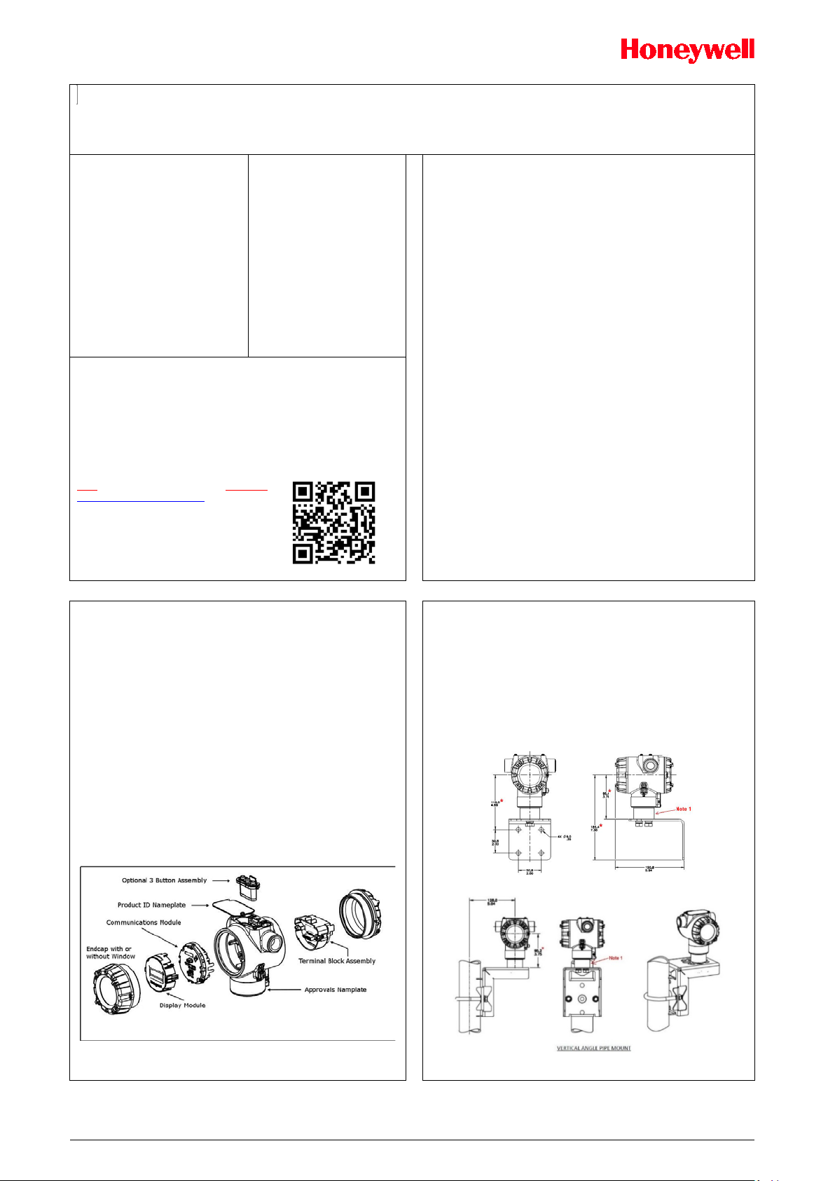
Features and options
The STT850 and STT750 are packaged in one major assembly: the Electronics
Housing.
The elements in the Electronic Housing are connected to the process sensors,
measure the process variables, respond to setup commands and execute the
software and protocol for the different temperature measurement types. Figure 1
shows the assemblies in the Electronics Housing with available options.
Mounting the Transmitter
Transmitter models can be attached to a two-inch (50 millimeter) vertical or
horizontal pipe using Honeywell’s optional angle; alternately you can use your own
bracket.
Honeywell’s optional wall mounting bracket is also shown below:
For Housing with Adaptor refer to Honeywell drawings 50095917 (Pipe mount) and
50095918 (Wall mount) for detailed mounting specifications.
For Housing without adaptor refer to Honeywell drawings 32306827 (No-Adaptor,
Pipe mount) and 32306828 (No-adaptor, Wall mount).
TRANSMITTER ENCLOSURE CAN BE ROTATED A TOTAL OF 90O
FROM THE STANDARD MOUNTING POSITION
Figure 2 –STT with adapter housing - Horizontal Wall Mounting
An optional 3-button assembly is located under the nameplate and provides a user
interface and operation capability without opening the transmitter to set up and make
Figure 1 – Electronics Housing Components
STT850/750 Quick Start Guide 1
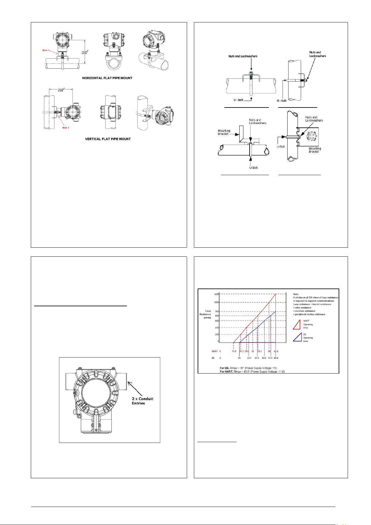
Optional Mounting Bracket
Position bracket on 2-inch (50.8 mm) and install “U” bolt around pipe and through holes
in bracket. Secure with nuts and lock washers provided. Optional mounting bracket, see
Figure 5
HORIZONTAL FLAT PIPE VERTICAL FLAT PIPE
Figure 4 - Pipe Mount with adapter housing - Horizontal & Vertical
Bracket Mounting
If you are using an optional brack et, s ta rt wit h Ste p 1.
1. Align the two mounting holes in the transmitter with the two slots
in the mounting bracket and assemble the (2) M8 hex cap
screws, (2) lockwashers and (2) flat washers provided. Rotate
transmitter assembl y to the desi re d pos it ion an d torq ue the M8
hex cap screws to 27,0 Nm/20,0 Lb-ft maximum.
2. Pipe Mount Option: Refer to Figure 5. Position the bracket on a 2-
inch (50.8 mm) horizontal or ve rt ical pip e, and i nst al l a “U” bol t
around the pipe and through the holes in the bracket. Secure the
bracket with the nuts, flat was he rs and l ock wash ers pr ov id ed.
3. Wall Mount Option: Position the bracket on the mounting surface
at the desired location and secure the bracket to the mounting
surface using the appropriate hardware (Wall mounting hardware
requirements to be determined and supplied by the end user).
Existing mounting bracket, see Fi gu re 5
Conduit Entry Plugs and Adapters
Procedures
It is the User/Installer’s responsibility to install the Transmitters in accordance
with national and local code requirements. Conduit entry plugs and adapters
shall be suitable for the environment, shall be certified for the hazardous
location when required and acceptable to the authority having jurisdiction for
the plant.
CONDUIT ENTRY PRECAUTIONARY NOTICE
THE CONDUIT/CABLE GLAND ENTRIES OF THIS PRODUCT ARE
SUPPLIED WITH PLASTIC DUST CAPS WHICH ARE NOT TO BE USED IN
SERVICE.
IT IS THE USER’S RESPONSIBILITY TO REPLACE THE DUST CAPS
WITH CABLE GLANDS, ADAPTORS AND/OR BLANKING PLUGS WHICH
ARE SUITABLE FOR THE ENVIRONMENT INTO WHICH THIS PRODUCT
WILL BE INSTALLED. THIS INCLUDES ENSURING COMPLIANCE WITH
HAZARDOUS LOCATION REQUIREMENTS AND REQUIREMENTS OF
OTHER GOVERNING AUTHORITIES AS APPLICABLE
.
Figure 5: Flat and Angle Mounting Brackets secured to Horizontal or Vertical Pipe
Wiring Connections and Power Up
Summary
The transmitter is designed to operate in a two-wire power/current loop with
loop resistance and power supply voltage within the HART and DE
operating ranges shown in Figure 7.
HORIZONTAL ANGLE PIPE VERTICAL ANGLE PIPE
Note. No plugs come installed in the housings. All housings come with
temporary plastic dust protectors (red) installed and are not certified for use
in any installation.
Figure 6: Electronic Hous ing Conduit Entries
*Only HART available for STT750 transmitter
For DE operation, add 3.0V to these values.
Loop wiring is connected to the Transmitter by simply attaching the positive
(+) and negative (–) loop wires to the positive (+) and negative (–) terminals
on the transmitter terminal block in the Electronics Housing, shown in
Figure 8.
Grounding Details:
Connect the Loop Power wiring shield to earth ground only at the power
supply end.
Note: The transm i tte r is not pol arity-sensitive.
Figure 7: HART* and DE Transmitter Operating Ranges
STT850/750 Quick Start Guide 2
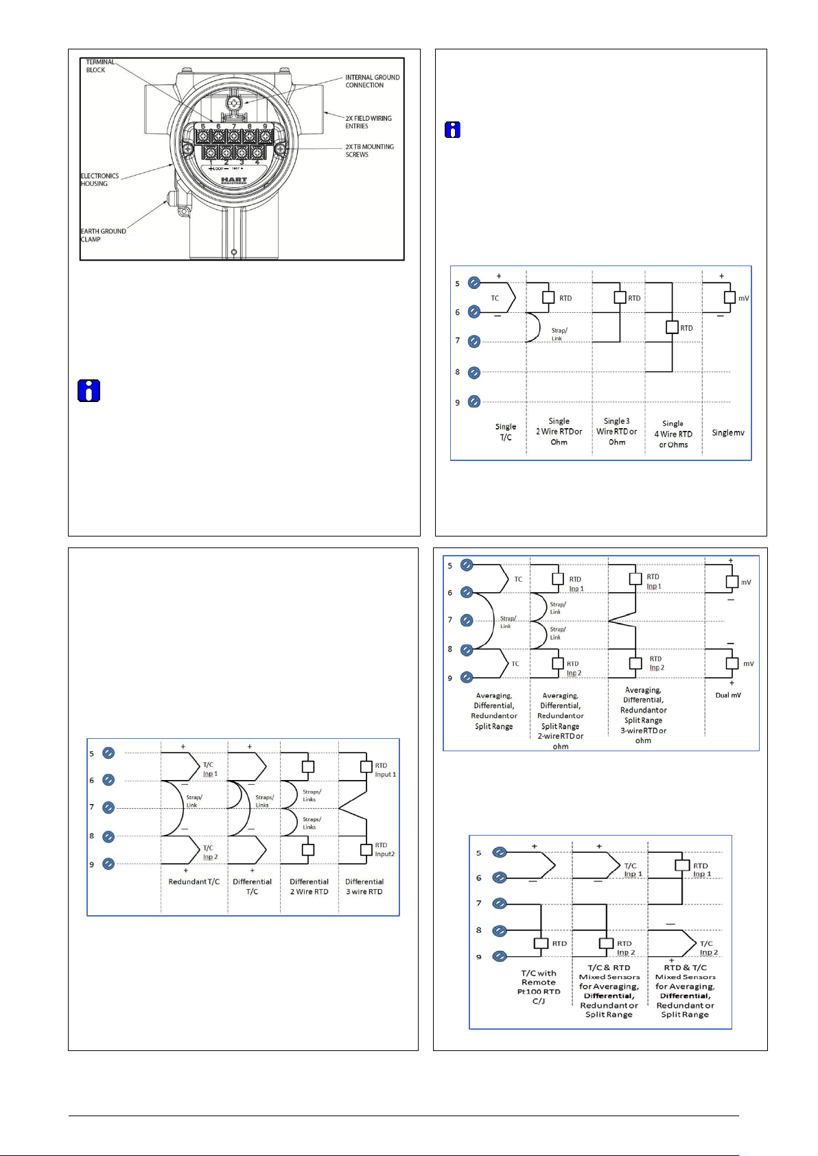
250 ohms of resistance (typically within the barriers) needed for digital communications.
Wiring Variations
Remote C/J and Mixed Sensors Connections
The above procedures are used to connect power to a Transmitter. For loop wiring and
external wiring, detailed drawings are provided for Transmitter installation in
non-intrinsically safe areas and for intrinsically safe loops in hazardous area locations.
This procedure shows the steps for connecting power to the transmitter.
Wiring must comply with local codes, regulations and ordinances. Grounding
may be required to meet various approval body certification, for example CE
conformity. Refer to the SmartLine Transmitter User’s Manual 34-TT-25-03
(STT850) or 34-TT-25-13 (STT750) for details.
NOTE: After wiring, torque the screws to around 4 to 5(lb-in). Maximum should not exceed 1.1 Nm (10 lb-in). Don’t pull the wires after connecting to the screw terminals.
Input Sensor Wiring
Connect the input sensors as shown in Figures below:
Figure 9: HART/DE/FF Single Input Wiring Diagram.
*Only HART available for STT750 transmitter
Figure 8: Transmitter 9-Screw Terminal Board and Grounding Screw
As shown in Figure 8, each Transmitter has an internal terminal to connect it to earth
ground. Connect sensor shield to the internal ground screw. The ground terminal can be
added to the outside of the Electronics Housing. Grounding the Transmitter for proper
operation is required, as doing so tends to minimize the possible effects of noise on the
output signal and affords protection against lightning and static discharge. An optional
lightning terminal block can be installed in place of the non-lightning terminal block for
Transmitters that will be installed in areas that are highly susceptible to lightning strikes. As
noted above, the Loop Power wiring shield should only be connected to earth ground at the
power supply end.
Wiring must comply with local codes, regulations and ordinances. Grounding may
be required to meet various approval body certification,
for example CE conformity. Refer to Appendix A of this document for details.
Note: Terminal #3 is for loop test and is not applicable for Fieldbus option.
Terminal #4 is for Digital Output and is not applicable for Fieldbus option.
Foundation Fieldbus not applicable to STT750
For HART and DE the Transmitter is designed to operate in a two-wire power/current loop
with loop resistance and power supply voltage within the operating range; see Figure 7
With an optional remote meter, the voltage drop for this must be added to the basic power
supply voltage requirements to determine the required Transmitter voltage and maximum
loop resistance. Additional consideration is required when selecting intrinsic safety barriers
to ensure that they will supply at least minimum Transmitter voltage, including the required
Figure 9: HART*/DE/FF Single Input Wiring Diagram
RTD Thermocouple, mV and Ohm Connections
Figure 10: DE Dual Input Wiring Diagram
• Resistance temperature detector (RTD) measurements use the 3 or 4 wire
approach.
• Dual-input units wired for a 4-wire RTD will automatically disable Input 2.
• DE dual input device needs to be power cycled whenever sensor input wiring
changed
• Supports dual thermocouple or RTD inputs for differential temperature
measurement
• Supports dual thermocouple sensor inputs for redundant sensor operation.
• To operate DE dual input device, it is required to connect both sensor inputs
• To minimize common noise problems in the application, a strap/jumper
For differential T/C operation on DE Models, a second strap/jumper should be wired
between terminals 6 and 7. Do not install this strap for Non-DE models. The output for
differential operation is calculated as T/C 1 - T/C 2.
should be wired between terminals 6 and 8.
Thermocouple and RTD Connections (not applicable to single input sensor)
Figure 10: DE Dual Input Wiring Diagram
DE not applicable to STT750 transmitter
STT850/750 Quick Start Guide 3
Figure 11: HART/FF – Dual Input Wiring Diagram
RTD Thermocouple, mV and Ohm Connections
Figure 12: HART/FF Dual Input Wiring Diagram
• For External C/J compensation, the first input is a thermocouple
type and the second input is a 3-wire PT100 ohm RTD
• The STT850 can have different sensor types on its inputs for split
range or averaging applications
Figure 12: HART/FF Dual Input Wiring Diagram, mixed sensors
 Loading...