

Page 1

STT750 Series HART Option
User’s Manual
34-TT-25-15
Revision 3.0
November 2020
Honeywell Process Solutions
Page 2

Copyrights, No tices and Trademarks
© Copyright 2020 by Honeywell, Inc.
Revision 3, November 2020
While the information in this document is presented in good faith and believed to be
accurate, Honeywell disclaims any implied warranties of merchantability and fitness for a
particular purpose and makes no express warranties except as may be stated in the written
agreement with and for its customers. In no event is Honeywell liable to anyone for any
indirect, special, or consequential damages. The information and specifications in this
document are subject to change without notice.
Honeywell, TDC 3000, SFC, SmartLine, PlantScape, Experion PKS, and TotalPlant are
registered trademarks of Honeywell International Inc. Other brand or product names and
service marks are the property of their respective owners.
Honeywell Process Solutions
2101 City West Blvd
Houston, TX 77042
Page ii STT750 Series HART/DE Option User’s Manual Revision 3.0
Page 3

About This Manual
This manual provides the details of programming Honeywell STT750 SmartLine Temperature
Transmitters for applications involving HART versions 5, 6, and 7 communication protocols. For
installation, wiring, and maintenance information
refer to the STT750 SmartLine Temperature Transmitter User Manual, document number
#34-TT-25-13.
The configuration of your transmitter depends on the mode of operation and the options selected
for it with respect to operating controls, displays and mechanical installation. Details for
operations involving the Honeyw ell Multi-Communication MC Toolkit (MCT404) are provided
only to the extent necessary to accomplish the tasks-at-hand. Refer to the associated MC Toolkit
User Manual, document # 34-ST-25-50 (MCT404) for complete details. The “Reference” section
in the front matter of this manual lists document titles and numbers.
The STT750 SmartLine Temperature Transmitter can be digitally integrated with one of two
systems:
• Experion PKS: you will need to supplement the information in this document with the data and
procedures in the Experion Knowledge Builder.
• Honeywell’s Tot alPlant Solutions (TPS): you will need to supplement the information in this
document with the data in the PM/APM SmartLine Tra nsmitte r Integration Manual, which is
supplied with the TDC 3000 book set. (TPS is the evolution of the TDC 3000).
Release Information
STT750 Series HART Option User Manual, Document # 34-TT-25-15 (this document)
Rev. 1.0, August 2015, 1
Rev. 2.0, March 2016 CVD, Soft DO, NE89 and RTD Cu10,
RTD Ni120 input details added
Rev. 3.0 November 2020 Series 2 updates
st
Release
References
The following list identifies publications that may contain information relevant to the information
in this document.
STT750 SmartLine Temperature Transmitter Quick Start Installation Guide, # 34-TT-25-14
SmartLine Temperature Transmitter w/ HART Comms Safety Manual, 34-TT-25-05
STT750 SmartLine Temperature Transmitter User Manual, # 34-TT-25-13
MC Toolkit User Manual, Document # 34-ST-25-20
PM/APM SmartLine Transmitter Integration Manual, # PM 12-410
STT750 Series Temperature, Transmitter, Agency IS Control Drawing, 50091227
MC Toolkit Modem Code Download Instruction Manual, Document # 34-ST-25-33
Revision 3.0 STT750 Series HART Option User’s Manual Page iii
Page 4
United States and
Canada
1-800-343-0228 Customer Service
1-800-423-9883 Global Technical Support
Global Email
Support
Honeywell Process
Solutions
Patent Notice
The Honeywell STT750 SmartLine Tempera tu re Tran smitter family is covered by one or more of the
following U. S. Patents: 5,485,753; 5,811,690; 6,041,659; 6,055,633; 7,786,878; 8,073,098 ; and other
patents pending.
Support and Contact Information
For Europe, Asia Pacific, North and South America contact details, see back page or refer to the
appropriate Honeywell Solution Support web site:
Honeywell Corporate www.honeywellprocess.com
Honeywell Process Solutions https://www.honeywellprocess.com/smartline-temperature/
Training Classes http://www.automationccollege.com
Telephone and Email Contacts
Area Organization Phone Number
Honeywell Inc.
ask-ssc@honeywell.com
Page iv STT750 Series HART Option User’s Manual Revision 3.0
Page 5

Contents
1 STT750 Physical and Functional Characteristics ........................................................................... 1
1.1 Overview ................................................................................................................................ 1
1.2 Features and Options .............................................................................................................. 1
1.2.1 Physical Characteristics .................................................................................................. 2
1.2.2 Functional Characteristics .............................................................................................. 3
1.3 STT750 SmartLine Transmitter NamePlate ........................................................................... 3
1.4 Safety Certification Information ............................................................................................. 3
1.5 Transmitter Adjustments ........................................................................................................ 3
1.6 Local Display Options ............................................................................................................ 4
1.7 Optional 3-Button Assembly .................................................................................................. 5
2 Communication Modes .................................................................................................................. 7
2.1 Overview ................................................................................................................................ 7
2.2 HART Mode Communication ................................................................................................ 7
3 Configuration Tools and Interfaces ................................................................................................ 9
3.1 Overview ................................................................................................................................ 9
3.2 Pre-requisites .......................................................................................................................... 9
3.3 Application Design, Installation, Startup, and Operation ....................................................... 9
3.3.1 Organization ................................................................................................................... 9
3.4 MC Toolkit Participation ...................................................................................................... 10
3.4.1 MC Toolkit Software Applications .............................................................................. 10
3.4.2 Configuration Databases .............................................................................................. 10
3.4.3 Configuration ................................................................................................................ 10
3.4.4 MC Toolkit–Transmitter Electrical/Signal Connections .............................................. 11
4 HART Transm itte r Co n figuration ................................................................................................ 13
4.1 Overview .............................................................................................................................. 13
4.1.1 Personnel Requirements ............................................................................................... 13
4.2 Overview of FDC Homepage ............................................................................................... 14
4.2.1 Settings ......................................................................................................................... 15
4.2.2 Manage DDs ................................................................................................................. 15
4.2.3 Online configuration ..................................................................................................... 18
4.2.4 Offline configuration .................................................................................................... 18
4.2.5 Online Configuration Overview ................................................................................... 18
4.2.6 Overview of Device Homepage ................................................................................... 19
4.2.7 Tabs on the Device Home page .................................................................................... 20
4.2.8 Using FDC for various device operations .................................................................... 22
4.2.9 Device Configurat ion and P aram eter Descrip ti ons ...................................................... 24
4.2.10 Procedure to Enter the Transm itter Tag ....................................................................... 39
4.2.11 Selecting the Process Variable (PV) Unit of Temperature Measurement .................... 39
4.2.12 Setting PV URV, and LRV Range Values ................................................................... 40
4.2.13 Setting Range Values for Applied Temperature ........................................................... 41
4.2.14 Saving device history ................................................................................................... 41
4.2.15 Exporting device history records to FDM .................................................................... 43
4.2.16 Exporting device history records to Documint ............................................................. 44
4.2.17 Custom Views .............................................................................................................. 44
4.2.18 Offline Configuration ................................................................................................... 46
Revision 3.0 STT750 Series HART Option User’s Manual Page v
Page 6

5 HART Calibration ........................................................................................................................ 50
5.1 About This Section .............................................................................................................. 50
5.1.1 About Calibration ......................................................................................................... 50
5.1.2 Input Calibration Procedure ......................................................................................... 50
5.1.3 Correct Input at URV ................................................................................................... 53
5.1.4 Equipment Required .................................................................................................... 55
5.2 Analog Output Signal Calibration ........................................................................................ 56
5.3 Calibrating Analog Inputs .................................................................................................... 57
5.3.1 Calibrate (Correct) Sensor Input at Lower Calibration Point (LRV Corrects) ............ 58
5.3.2 Calibrate (Correct) Sensor Input at Upper Calibration Point (URV Corrects) ............ 59
5.3.3 Resetting Calibration.................................................................................................... 59
5.3.4 STT750 Calibration Records ....................................................................................... 60
6 HART Advanced Diagnostics ...................................................................................................... 61
6.1 About This Section .............................................................................................................. 61
6.2 Advanced Diagnostics.......................................................................................................... 61
6.2.1 Installation and Device Life ......................................................................................... 62
6.2.2 PV Tracking Diagnost ics ............................................................................................. 64
6.2.3 SV Tracking ................................................................................................................. 66
6.2.4 Comm Board ET Tracking Diagnostics ....................................................................... 67
6.2.5 Sensor Board ET Tracking Diagnostics ....................................................................... 69
6.2.6 Operating Voltage Diagnostics .................................................................................... 69
6.2.7 Sensor Supply Voltage (AVDD) Tracking Diagnostics .............................................. 70
6.2.8 Sensor CPU Temperature Tracking Diagnostics ......................................................... 70
6.2.9 Power Cycles ............................................................................................................... 72
7 Troubleshooting and Maintenance ............................................................................................... 73
7.1 HART Diagnostic Message s ................................................................................................ 73
7.2 HART Diagnostic Details .................................................................................................... 74
8 Using DTMs ................................................................................................................................. 75
8.1 Introduction .......................................................................................................................... 75
8.2 Components ......................................................................................................................... 75
8.3 Downloads ........................................................................................................................... 75
8.4 Procedure to Install and Run the DTM ................................................................................ 75
8.5 STT750 Online Parameterization ......................................................................................... 76
8.5.1 Key Parameters ............................................................................................................ 76
8.6 Basic Setup Page .................................................................................................................. 77
8.6.1 Device Information: ..................................................................................................... 77
8.7 STT750 Offline Parameterization ........................................................................................ 78
9 HART DD Binary File Format Compatibility Matrix ................................................................. 79
Glossary ............................................................................................................................................... 80
Page vi STT750 Series HART Option User’s Manual Revision 3.0
Page 7

List of Figures
Figure 1 – STT750 Major Assem blies ................................................................................................... 2
Figure 2 – Electronics Housing Components ......................................................................................... 2
Figure 3 –Typical STT750 Nameplate ................................................................................................... 3
Figure 4 – HART Point-to-Point and Multi-drop Value Scaling ........................................................... 7
Figure 5 – MC Toolkit-Transmitter Electrical/Signal Connections ..................................................... 11
Figure 6 – FDC Homepage................................................................................................................... 14
Figure 7 – Device Homepage ............................................................................................................... 19
List of Tables
Table 1 – Features and Options .............................................................................................................. 1
Table 2 – Available Display Characteristics .......................................................................................... 4
Table 3 – User Manual Related Topics .................................................................................................. 9
Table 4 – FDC homepage elements ...................................................................................................... 14
Table 5 – Device health status .............................................................................................................. 19
Table 6 – HART Transmitter Param eters ............................................................................................. 24
Table 7 – Tamper Reporting Logic Implementation with Write Protect .............................................. 38
Table 8 – Calibration Records .............................................................................................................. 60
Table 9 – Viewing Advanced Diagnostics ........................................................................................... 61
Table 10 – Maximum PV Tracking ...................................................................................................... 64
Table 11 – Minimum PV Tracking ...................................................................................................... 65
Table 12 – Maximum SV Tracking ...................................................................................................... 66
Table 13 – Minimum SV Tracking ...................................................................................................... 66
Table 14 – Maximum ET Diagnostics .................................................................................................. 67
Table 15 – Minimum ET Diagnostics .................................................................................................. 68
Table 19 – Sensor Board ET Diagnostics ............................................................................................. 69
Table 16 – Operating Voltage Diagnostics........................................................................................... 69
Table 17 – Maximum and Minimum AVDD Tracking ........................................................................ 70
Table 18 – Maximum Sensor CPU Temperature Tracking .................................................................. 70
Table 19 – Minimum Sensor CPU Temperature Tracking ................................................................... 72
Table 20 – Power Cycles ...................................................................................................................... 72
Table 21 – HART Diagnostic Messages .............................................................................................. 73
Table 22 – HART Critical and Non-Critical Diagnostic Details .......................................................... 74
Revision 3.0 STT750 Series HART Option User’s Manual Page vii
Page 8

This page has been intentionally left blank
Page viii STT750 Series HART Option User’s Manual Revision 3.0
Page 9
Communication Protoco ls
HART
Human-Machine Interface (HMI) Options
Basic Digital Display
Three-button programming (optional)
Basic display language: English only
Calibration
Single
Approvals (See Appendix C for details.)
ATEX, CSA, FM, IECx, NEPSI
Mounting Brackets
Angle/flat carbon steel/304 stainless steel, Marine
304 stainless steel
Integration Tools
Experion, FDM and DTM
1 STT750 Physical an d Functional Characteristics
1.1 Overview
This section is an introduction to the physical and functional characteristics of Honeywell’s family of
STT750 SmartLine Temperature Tr ansm itt er s.
1.2 Features and Options
The STT750 SmartLine Temperature Transmitter is available in a variety of models for measuring
Thermocouples, RTD, Millivolts, and Volt or ohm sensor types. Table 1 lists the protocols, human
machine interface (HMI), materials, approvals, and mounting bracket options for the STT750.
Table 1 – Features and Options
Feature/Option Standard/Available Options
(Basic Display)
Revision 3.0 STT750 Series HART Option User’s Manual Page 1
Page 10
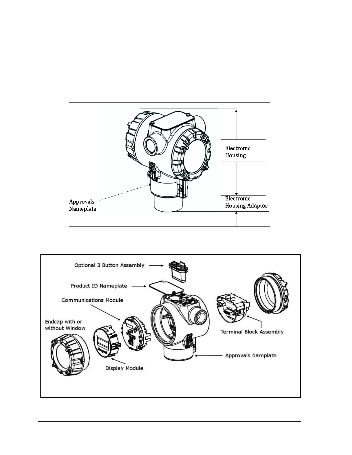
1.2.1 Physical Characteristics
As shown in Figure 1, the STT750 is packaged in one major assembly: The Electronics Housing. The
elements in the Electronic Housing are connected to the process sensors, measure the process
variables, respond to setup commands and execute the software and protocol for the different
temperature measurement types. Figure 2 shows the assemblies in the Electronics Housing with
available options.
Figure 1 – STT750 Major Assemblies
Figure 2 – Electronics Housing Components
Page 2 STT750 Series HART Option User’s Manual Revision 3.0
Page 11
• T = Temperature
1.2.2 Functional Characteristics
The transmitter measures process temperature and outputs a signal proportional to the measured
process variable (PV). Available output communication protocols include analog 4 to 20 mA and
HART protocol.
An optional 3-button assembly is available to set up and m ak e adjustm ents to the transm itter. In addition,
a Honeywell Multi-Communication MC Toolkit (MCT404) (not supplied with the transmitter) can
facilitate setup and adjustment procedures in the case of HART.
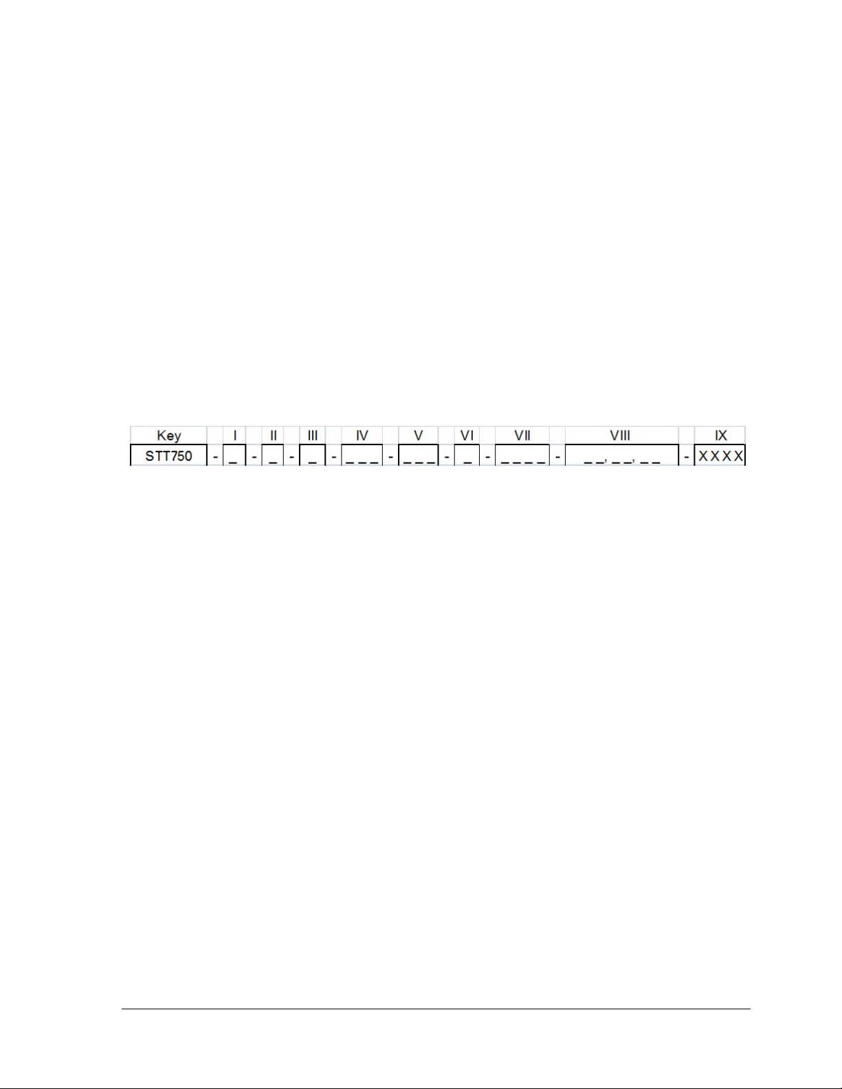
1.3 STT750 SmartLine Transmitter NamePlate
The Transmitter nameplate mounted on the top of the Electronics Housing (see Figure 2) lists the
model number, physical configuration, electronics options, accessories, certifications, and
manufacturing specialties. Figure 3 is an example of a typical STT750 temperature Name plate. The
model number format consists of a Key Number with several table selections.
Figure 3 –Typical STT750 Nameplate
You can readily identify the series and basic transmitter type from the key number. The letter in the
third digit represents one of these basic transmitter types:
For a complete selection breakdown, refer to the appropriate Specification and Model Selection Guide
provided as a separate docum ent.
1.4 Safety Certification Information
An “approvals” name plate is located on the bottom of the Electronics Assembly; see Figure 1 for
exact location. The approvals name plate contains information and service marks that disclose the
transmitter compliance information. Refer to Appendix A in the STT750 SmartLine Transmitters
User’s Manual, document number 34-ST-25-13 for details.
1.5 Transmitter Adjustments
Span adjustments are possible in new generation STT750 SmartLine Temperature Transmitters by
using the optional 3-button assembly located at the top of the Electronic Housing, see Optional 3-
Button Assembly on page 5. However, certain c ap ab il i ties are limited in th e fo l lo w ing configurat ion s :
• Without a display –Span setting only for a HART device.
• With a display – Complete transm itter configuration is possible for a HART device.
Revision 3.0 STT750 Series HART Option User’s Manual Page 3
Page 12

For HART you can also use the Honeywell MC Toolkit or other third-party hand-held to make any
adjustments to an STT750 SmartLine Temperature Transmitter. Alternately, certain adjustments can
be made through the Experion or Universal Station, if the transmitter is digitally integrated with a
Honeywell Experion or TPS system.
.
1.6 Local Display Options
The STT750 Temperature Transmitter has a Basic Digital Display; see Table 2
.
Table 2 – Available Display Characteristics
• Suitable for basic process needs
o
rotation in 90o Increments
Basic Display
• 360
• 8 configurable screens
• 2 lines, 16 characters
• Standard engineering units
• Diagnostic messaging
• Supports optional 3-Butt on c onf igurat ion and calibr at io n
Page 4 STT750 Series HART Option User’s Manual Revision 3.0
Page 13

1.7 Optional 3-Button Assembly
The optional 3-button assembly is located under the nameplate and p rovides the following features:
• Opportunity for immediate reaction with minimal disruptions
• Improved maintenance time
• Potential savings on hand-held units
• Suitable for all environments: hermetically sealed for long life in harsh environments
• Suitable for use in all electrical classifications (flameproof, dustproof, and intrinsically safe)
The 3-button assembly is externally accessible and provides the following capabilities:
• Menu-driven configuration with optional display:
o Using increment, decrement & enter keys
o A comprehensive on screen menu guides the way
o Configure the transmitter
o Configure the display
o Set span
• Zero and span settings without optional display
Revision 3.0 STT750 Series HART Option User’s Manual Page 5
Page 14

This page is left blank intentionally.
Page 6 STT750 Series HART Option User’s Manual Revision 3.0
Page 15
2 Communication Modes
2.1 Overview
The STT750 SmartLine Temperature Transmitter can be configured for operation with HART version
7 communication. This manual addresses the processes to configure and calibrate a transmitter for
HART communication.
2.2 HART Mode Communication
When using MCToolkit (MCT404), but before connecting to a HART transmitter, verify that
the FDC application is used and not the MC Toolkit application.
• Transmitters with HART capability have features that vary among manufacturers and with the
characteristics of specific devices. The FDC software application executing on the MCT404
supports the HART Universal, Common Practice and Device Specific Commands which are
implemented in the Honeywell transmitters.
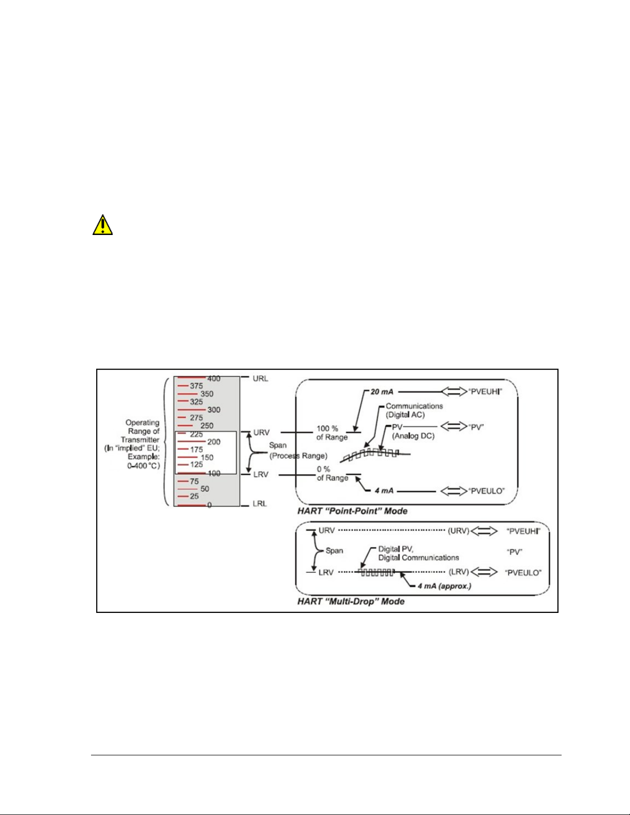
As indicated in Figure 4, the output of a transmitter co nfig ured for HART protocol includes two
primary modes:
Figure 4 – HART Point-to-Point and Multi-drop Value Scaling
• Point-to-Point Mode, in which one transmitter is connected via a two-conductor, 4-20 mA
current loop to one receiver.
• Multi-Drop Mode, in which several transmitte rs are co nnec ted through a two-conductor
network to a multiplexed receiver device.
Revision 3.0 STT750 Series HART Option User’s Manual Page 7
Page 16

In point-to-point mode, the value of the primary Process Variable (PV) is represented by a 4-20 mA
current loop, almost identical to that of a tr ansm itter operating in analog m ode. You can also have one
device in analog output mode when you are configured as multi-drop. In this case, however, the analog
signal is modulated by Frequency Shift Keying (FSK), using frequencies and current amplitude that do
not affect analog sensing at the receiver. The accuracy of the analog level must be precisely controlled
for accurate sensing. HART communication will not bump process variables.
In multi-drop mode, up to 16 transmitters in HART 5 (addresses 0-15) and up to 64 transmitters in
HART6/7 (addresses 0-63) can exist on the two-conductor network.
Page 8 STT750 Series HART Option User’s Manual Revision 3.0
Page 17

Site evaluation
Startup tasks and procedures
3 Configuration Tools and Interfaces
3.1 Overview
This section describes the tools and interfaces involved in configuring a new STT750 SmartLine
Temperature Transmitter for HART communication operation. The information in this section also
applies to adjusting the configuration of a transmitter that has been in operation and updating one that
is currently in operation.
3.2 Pre-requisites
The information and procedures in this manual are based on the assumption that personnel performing
configuration and calibration tasks are fully qualified and knowledgeable in the use of the Honeywell
MCT404. The name MC Toolkit (MCT404) are used interchangeably as MCT404 is the model name
for the Honeywell MC Toolkit product. Furthermore, we assume that the reader is intimately familiar
with the STT750 family of SmartLine Temperature Transmitters and thoroughly experienced in the
type of process application targeted for transmitter deployment. Therefore, detailed procedures are
supplied only in so far as necessary to ensure satisfactory completion of configuration tasks.
3.3 Application Design, Installation, Startup, and Oper a ti on
The STT750 SmartLine Temperature Transmitters User’s Manual, document number 34-ST-25-13,
provides the details for application design, installation, and startup; see Table 3 for topics.
Table 3 – User Manual Related Topics
STT750 SmartLine Temperature Transmitters Users Manual
Section 2. Application Design Section 3. Installation and Startup Section 4. Operation
Safety and accuracy
Diagnostics messages
Design consideration
Toolkit issues
Display installation concerns
Transmitter mounting & zerocorrection
Wiring
Three-button option
Failsafe (burnout)
direction setup
Monitoring displays
3.3.1 Organization
This information in this section is arranged in the following sequence:
• MC Toolkit participation in STT750 transmitter setup and configuration:
o Physical circuit connection s
o Application components
o Configuration for Analog and HART operation
• STT750 Transmitter
o Basic display
o Health indications
o Ability to be configured and operate in a process system
Revision 3.0 STT750 Series HART Option User’s Manual Page 9
Page 18

3.4 MC Toolkit Participation
Before using the MC Toolkit, be sure that you are aware of the potential consequences of
each procedure, and that you use appropriate safeguards to avoid possible problems. For
example, if the transmitter is an element in a control loop, the loop needs to be put in manual
mode, and alarms and interlocks (i.e., trips) need to be disabled, as appropriate, before starting
a procedure.
3.4.1 MC Toolkit Software Applications
The MC Toolkit has two software applications to work with STT750 SmartLine Temperature
Transmitters:
• Field Device Configurator (FDC). This application is used for configuring, calibrating,
monitoring, and diagnosing HART devices. FDC conforms to the IEC 61804-3 EDDL
(Electronic Data Desc riptio n Lang uage) stan dard specific ation. The FDC application is an open
solution that supports devices with a registered device description (DD) file compatible with
HART Communication Foundation (HCF) requirements.
Details for work in g with the MC Toolkit are provided in the MC Toolkit User Manual, document,
#34-ST-25-50 (MCT404). In subsequent sections of this manual, explicit operating instructions are
provided only in so far as necessary to complete required tasks and procedures.
3.4.2 Configuration Databases
The MC Toolkit is used to establish and/or change selected operating pa ram eters in a transmitter
database.
3.4.3 Configuration
Configuration can be accomplished both online and offline with the transmitter powered up and
connected to the MC Toolkit. Online configuration immediately changes the transmitter operating
parameters. For offline configuration, transmitter operating characteristics are entered into Toolkit
memory for subsequent downloading to a transmitter.
When you set up or configure a transmitter, it can take up to 30 seconds for the value to
be stored in it. If you change a value and transmitter power is interrupted before the change
is copied to nonvolatile memory, the changed value will not be moved to nonvolatile memory.
Page 10 STT750 Series HART Option User’s Manual Revision 3.0
Page 19
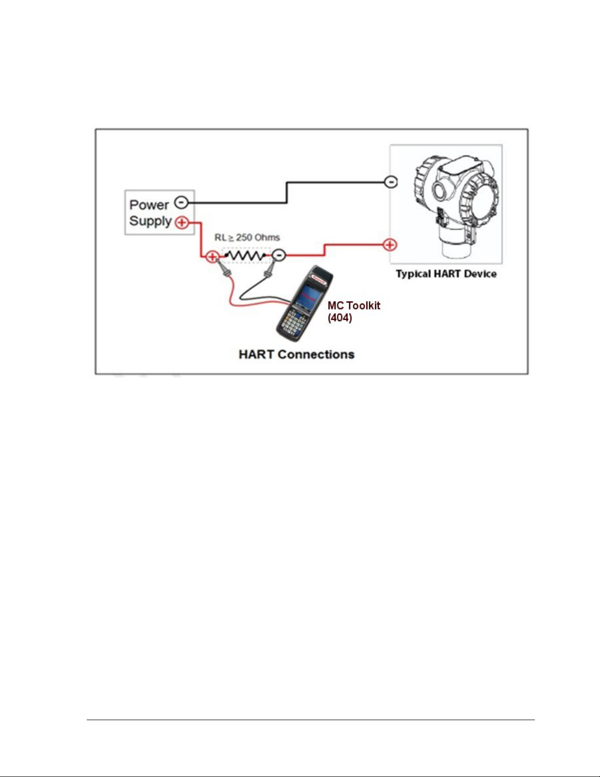
3.4.4 MC Toolkit–Transmitter Electrical/Signal Connections
Figure 5 displays how to connect the MC Toolkit directly to the terminals of a HART-only transmitter
(bottom).
Figure 5 – MC Toolkit-Transmitter Electrical/Signal Connections
Revision 3.0 STT750 Series HART Option User’s Manual Page 11
Page 20

This page is left blank intentionally.
Page 12 STT750 Series HART Option User’s Manual Revision 3.0
Page 21

4 HART Transmitter Configuration
4.1 Overview
Each new STT750 Temperature Transmitter configured for HART protocol is shipped from the factory
with a basic configuration database installed. This basic configuration database must be edited or
revised to meet the requirements of your process system. The process in this section assumes that you
will use the Field Device Communicator (FDC) application for HART configura tion tasks. The FDC
application provides the facilities for the online and offline configuration of trans mitters operating with
HART protocol
Online configuration requires that the transmitter and MC Toolkit are connected and communication
between the two has been established. Online co nfiguration provides a set of functions with which to
perform various operations on a HART communication network through an active communication
link. These operations primarily include configuration, calibration, monitoring, and diagnostics.
Typically, these operations could be realized through various constructs exposed by the Device
Description (DD) file. In addition, the FDC application provides some functions for convenient
execution of these functions.
Offline Configuration refers to configuring a device when the device is not physically present or
communicating with the application. This process enables you to create and save a configuration for a
device, even when the device is not there physically. Later when the device becomes available with
live communication, the same configuration can be downloaded to the device. This feature enables you
to save on device commissioning time and even helps you to replicate the configuration in multiplicity
of devices with lesser efforts. Currently, FDC does not support creating offline configuration.
However, it supports importing of offline configuration from FDM R310 or later versions. The
configurations thus imported can be downloaded to the device from FDC.
The following are the tasks that you need to perform for importing offline configuration in FDC
application software and then downloading it to the device.
• Create offline configuration template in FDM
• Save the configuration in FDM in FDM format.
• Import the offline configuration in FDC
• Download the offline configuration to the device
Note: For details on creating and using offline configuration, refer to section Offline configuration in
FDM User’s Guide.
4.1.1 Personnel Requirements
The information and procedures in this section are based on the assumption that the person
accomplishing configuration tasks is fully qualified and knowledgeable on the use of the MC Toolkit
and is intimately familiar with the STT750 family of SmartLine Temperature Transmitters. Therefore,
detailed procedures are supplied only in so far as necessary to ensure satisfactory configuration. The
other HART configuration tools are Honeywell Experion in conjunction with FDM, iDTMs running
on FDM or Pactware, and Emerson 375/475. The organization of Device Configuration and Parameter
Descriptions on page 24 is given in
Revision 3.0 STT750 Series HART Option User’s Manual Page 13
Table 6.
Page 22
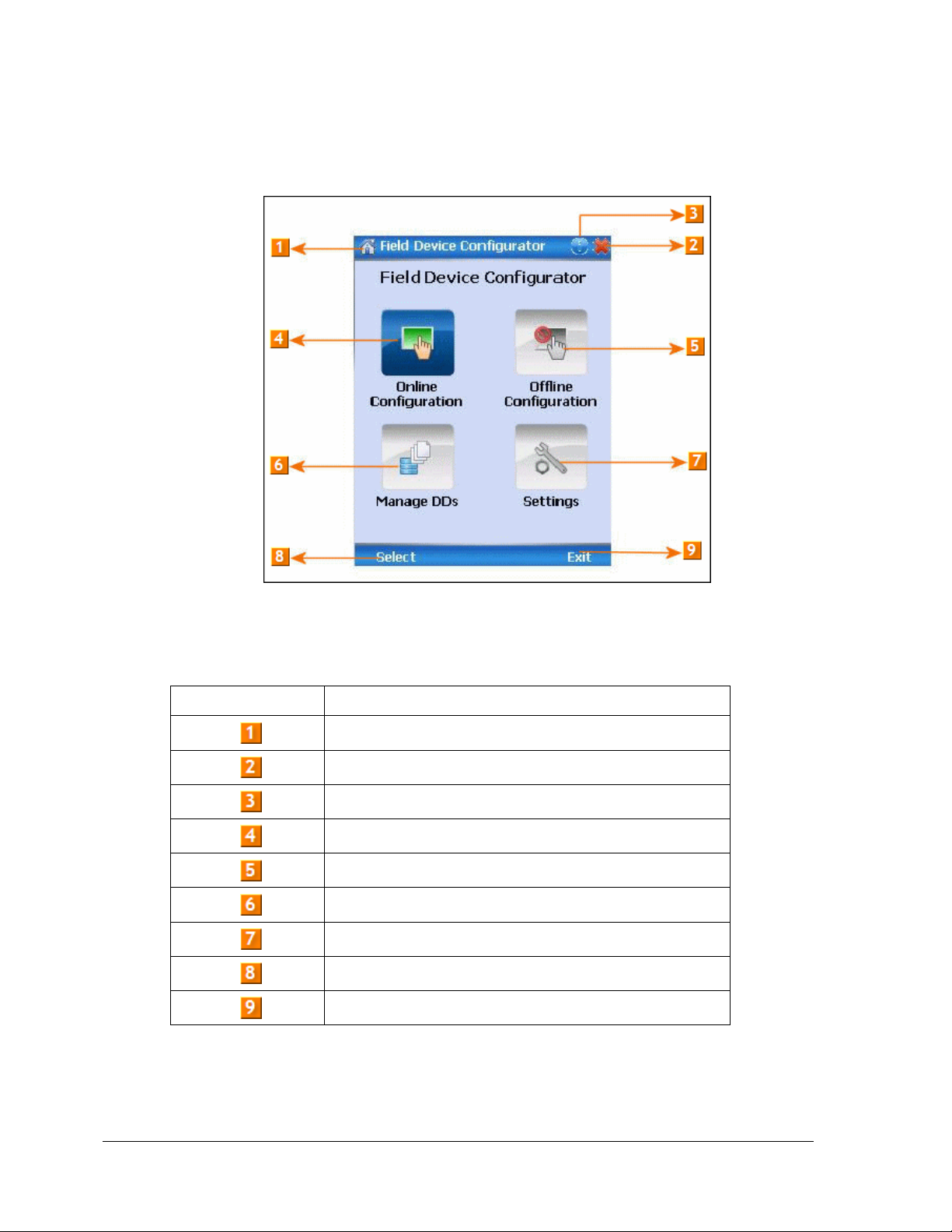
4.2 Overview of FDC Homepage
The FDC homepage consists of links for Online Configuration, Offline Configuration, Manage DDs,
and Settings. See below.
Figure 6 – FDC Homepage
Table 4 lists the items that appear on the FDC homepage and its descriptions.
Table 4 – FDC homepage elements
Items Description
Screen title.
Tap to quit FDC.
Tap to view the application information.
Tap to navigate to Online Configuration screen.
Tap to navigate to Offline configuration screen.
Tap to navigate to Manage DDs screen.
Tap to navigate to Settings screen.
Tap to select the highlighted menu option.
Tap to quit FDC.
Note: To select a particular option in FDC you can either select the option and then tap Select or you
can directly double-tap the option.
Page 14 STT750 Series HART Option User’s Manual Revision 3.0
Page 23

4.2.1 Settings
Use this feature to customize FDC. You can customize FDC for device detection, DD selection, and
other application settings.
4.2.1.1 Device Identification
Use the following options to configure FDC to identify a device.
• Using Poll Address
− Use poll address 0 only: Use this to detect a device with the poll address as zero.
− Find first poll address and use: Use this to detect a device with the first available
poll address in the range of poll addresses that are avai lab le.
− Use selected poll address: Use this to detect a device with a specific poll address in
the range of zero to 63.
− Use From: Use this to detect a device based on a range of poll addresses.
Using Device TAG: Use this to detect a device with a known HART tag.
•
Using Device LONG TAG: Use this to detect a device with a known HART long tag
•
(applicable for devices with HART 6 or later Universal revisions).
Note: If you choose the option Using Device TAG or Using Device LONG TAG, FDC prompts you to
enter a device tag/long tag name during device detection.
4.2.1.2 DD selection
Use the following options to configure FDC to select DD files when a DD with matching device
revision is not available.
- Use DD file of previous device revision: Use this option to automatically communicate using
a DD file having device revision lower than that of the device.
- Use generic DD file: Use this option to automatically communicate to the device using an
appropriate generic DD file.
- Always ask user: Use this option to always prompt you with a choice for communicating to
the device either using the previous device revision or using a generic DD file.
- Always Use Generic: Use this option to always communicate to the device using generic DD
files even if a DD file with matching device revision as the device is present.
Note: A generic DD file is a DD file that provides access and interface to the universal data and
features of a HART device.
4.2.1.3 Other settings
Low storage notification: Use this option to set a percentage value and to notify you with a warning
message when the available storage card space is less than the percentage set.
Application diagnostics: Use this option to enable or disable the logging infrastructure for application
diagnostics. With this option enabled, FDC creates necessary log files for troubleshooting and
diagnostics. These files are stored in SD Card\FDC folder.
Note: You must not enable this option unless suggested by Honeywell TAC because this may impact
the application performance.
4.2.2 Manage DDs
Using this feature, you can manage the DD files installed with FDC. A DD file contains descriptive
information about the functionality of a device. By default, a set of DD files are installed with FDC.
Revision 3.0 STT750 Series HART Option User’s Manual Page 15
Page 24
However, if you do not have a DD for a given device, you can install it using the “Add DD” feature.
Similarly, you can uninstall a DD file or a set of DD files using “Delete DD” feature. You can also
directly copy the DD files in appropriate hierarchy using a card reader or “Active Sync/Mobile Device
Center” mechanisms. In such a case, you should validate the library view using the “Refresh” feature.
4.2.2.1 Overview
Using Manage DDs, you can view, add, or delete DD files for devices. A list of already available DD
files is maintained in the DD Library. FDC lists the installed DD files in a hierarchy as below:
Manufacturer
Device Type
DevRev xx, DDRev yy
DevRev pp, DDRev qq
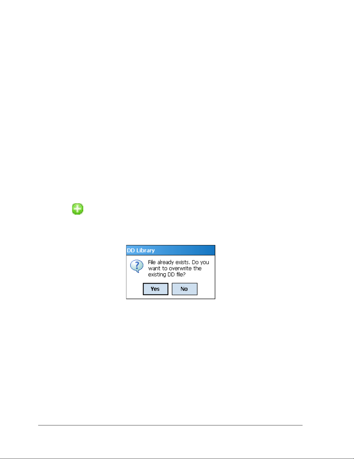
4.2.2.2 Add a DD file
To add a DD file for a device, perform the following steps.
1. From the FDC homepage, tap Manage DDs > Select.
The Manage DDs dialog box appears.
2. Tap Options > Add DD.
Or
Tap .
The ADD DD files dialog box appears.
3. Browse to the location in which the DD file (.fm8) is located and tap OK.
4. If the DD file already exists, then the following message appears.
5. Tap Yes to overwrite the existing DD files.
6. If the DD file is added successfully, a success message appears.
Page 16 STT750 Series HART Option User’s Manual Revision 3.0
Page 25

4.2.2.3 Delete a DD file
Using this option, you can delete a particular version of a DD file. To delete a DD file for a device,
perform the following steps.
1. From the FDC homepage, tap Manage DDs > Select.
The Manage DDs dialog box appears.
2. You can choose to delete DD(s) in one of the following ways:
a) By device manufacturer – Select a device manufacturer to delete all device types and
DDs associated with the manufacturer’s devices.
b) By device type – Select a device type to delete all DDs associated with the device.
c) By device revision and DD revision – Select the specific entry of device revision, DD
revision to delete the specific DD
3. Tap Options > Delete DD.
Or
Tap .
A confirmation message appears.
4. Tap Yes.
If the DD file is deleted successfully, a success message appears.
5. Tap OK to return to DD Library page.
4.2.2.4 Validating a manually edited library
Besides using the Add/Delete DD features, advanced users may also manipulate a DD library by
directly editing the contents of the FDC\Library folder. DD files can also be transferred directly to this
location by accessing the SD Card on MCT101 through a card reader and/or by connecting the
MCT404 to a PC. In such cases, you must perform the following steps to validate a DD Library, thus
edited manually:
1. From the FDC ho mepage , tap Manage DDs > Select
The Manage DDs dialog box appears
2. Tap Options.
3. Tap Refresh Library.
Or
Tap .
A confirmation message appears.
4. Tap Yes. The DD library is now validated and refreshed.
Revision 3.0 STT750 Series HART Option User’s Manual Page 17
Page 26

4.2.3 Online configuration
Using online configuration, you can configure, calibrate, monitor and diagnose a HART device which
is connected to MC Toolkit. FDC provides the features to perform these functions through the various
constructs offered through the DD file of the device. Besides there are certain other features available
under this link for you to conveniently work with a HART device with live communication. After
making changes to the device you can also save a snapshot of the device data as history to later
transfer it to FDM for record and audit purposes.
4.2.4 Offline configuration
Offline configuration refers to configuring a device offline (without physically connecting to
the device) using a template and then downloading the configuration to the device. Presently,
FDC application software does not support creating offline configuration. However, it
supports importing of offline configuration from FDM (R310 and above).
4.2.5 Online Configuration Overview
Online Configuration option provides you a set of functions with which you can perform various
operations on a device with an active communication link. These operations primarily include
configuration, calibration, monitoring, and diagnostics of a HART device. Typically, these operations
could be realized through various constructs exposed by the DD file of the device. In addition, FDC
also provides some additional application functions for you to perform these functions more
conveniently.
Online configuration includes a set of functions to perform various operations on a transmitter with
active communication link. These operations primarily include:
• Identifying a transmitter
• Reading and reviewing transmitter variable values
• Editing transmitter variable values
• Downloading the selected/edited variable set to the transmitter
4.2.5.1 Detecting and loading a device
Tap the Online Configuration button on the Application Home page.
The device detection and loading process automatically gets started. Depending upon the Device
Detection and DD Selection settings you may have chosen, you may be prompted for certain inputs as
described in the Settings section.
Page 18 STT750 Series HART Option User’s Manual Revision 3.0
Page 27
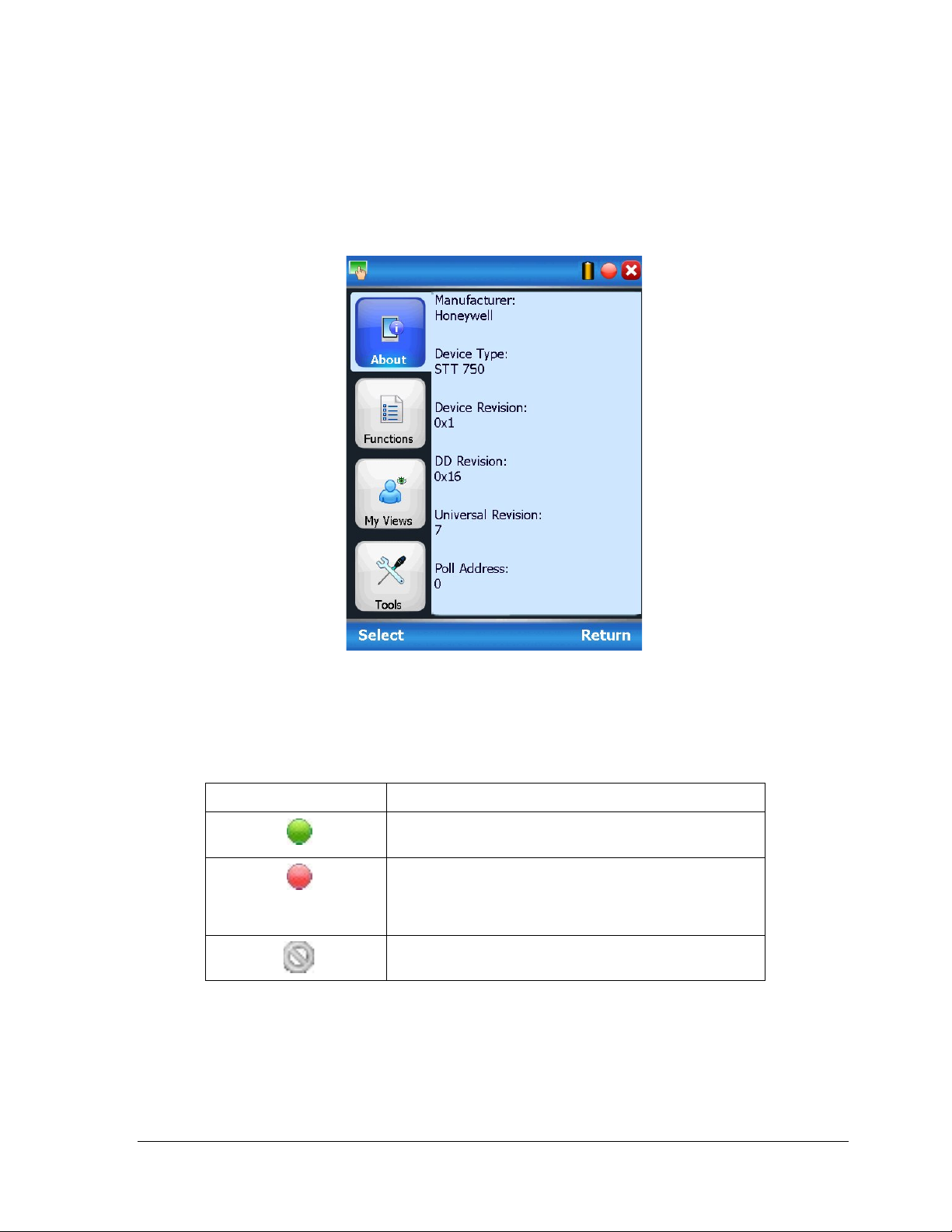
4.2.6 Overview of Device Homepage
Once the device is detected and loaded successfully, you can view the device homepage for the
identified device.
The workspace area on the device homepage consists of 4 tabs on the left hand side. Selecting a tab
displays functions/information associated with that tab on the right hand side.
Figure 7 – Device Homepage
Table 5 lists the device health status and their indications.
Table 5 – Device health status
Device health icons Indications
Indicates there’s no health or status indicators reported
by the device
Indicates that the device is potentially reporting a status
which needs attention and further investigation. It is
advised that you use Device Status under Functi ons tab
to further investigate the details.
Indicates that the device has lost communic atio n w ith M C
Toolkit
Revision 3.0 STT750 Series HART Option User’s Manual Page 19
Page 28
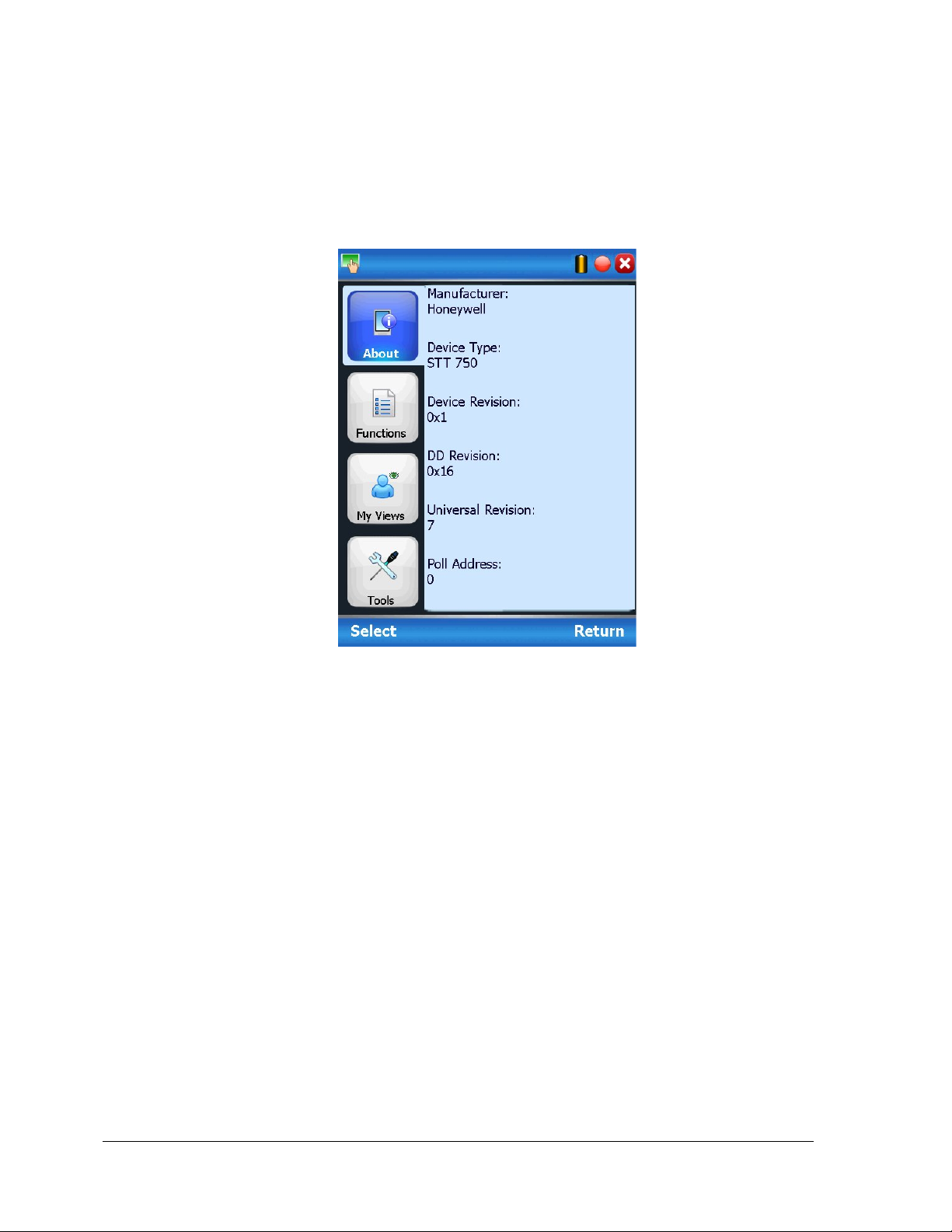
4.2.7 Tabs on the Device Home page
The following are the options that are available on the device homepage
• Information tab: Use this option to view the device identity related information. You can
view the manufacturer name, device type, device revision, DD revision, and universal
revision of the HART device.
• Functions tab: This tab provides various options which you may use for navigating
through the device specific user interface and some standard features offered by FDC
across all devices. For the sake of explanations, the right side options under this tab shall be
referred as “Entry points” throughout the rest of the document.
Page 20 STT750 Series HART Option User’s Manual Revision 3.0
Page 29

• My Views tab: Quite often, you may be interested only in a set of variables of a device.
But navigating through the menu tree of a device may not be helpful because of time and
further all variables that you want may not be in the same location. Using this unique
feature of FDC, you can now choose what you want to view in a device in your own views.
FDC allows you to create two such views per device revision of a specific device type. You
can always modify them as per your needs.
• Tools tab: This tab is a placeholder for FDC specific tools for providing certain functionality.
Currently t he only option it provides is called as Save History. Using thi s option you can save the
snapshot of the device variables. This snapshot is saved in a format which can be later imported as a
history record in FDM.
Revision 3.0 STT750 Series HART Option User’s Manual Page 21
Page 30

4.2.8 Using FDC for various device operations
Typical operations with a smart field device involve configuration, calibration, monitoring, and
diagnostics. FDC enables you to achieve these operations with a HART device via the various
interfaces/constructs exposed through the DD file of the device.
The “Functions” tab under the device home page provides the entry points for navigating through the
device specific user interface to perform the above mentioned operations. A device may define up to
four entry points in the DD file. All devices shall have at least one entry point, generally referred to as
“Online”. Besides the device specific entry points, FDC provides custom entry points for navigational
aids to specific ty pe s of information/features. One such entry point is called Device Status, which is
used for reviewing device health. Another is called Methods List, which is used to navigate to all the
methods available in a device.
All of the device specific entry points represent the device interface, as explained using the Online
entry point as an example. All the other device specific entry points have a similar interface except for
the fact that the variables and other DD constructs provided under each may vary as indicated by the
title of each entry point.
For the sake of explanation, the pages that appear on navigating through the device
specific entry points are referred to as “Device Configuration” pages in this document. However
it must be noted that this does not prohibit you from performing other device operations as
explained above.
Page 22 STT750 Series HART Option User’s Manual Revision 3.0
Page 31

Online Device Entry Point: When you tap on to open the Online tab, the device configuration screen
appears as shown below.
Typical Online Menu is shown below. Based on the connected Device type, Menu items will be shown
Alternately you can access the full EDDL features by selecting the “My Device” Tab. Typical My
Device Tab is shown. Based on the connected device type Menu items will be show n
Navigate through the Menus to access various functions. See Table 6 for lists all the parameters in the
STT750.
Revision 3.0 STT750 Series HART Option User’s Manual Page 23
Page 32

Online Menu Flow
Parameter menu/
name
Description/Valid values
Tag
Enter tag identification up to eight
alphanumeric characters.
PV(Loop)
Displays the current value of the
engineering units
AO Alrm Typ
Displays the current position of the
Loop Test
This function enables the user to
Current mode) is Enabled.
Online/Device Settings/ Ke y
PV UTL
Displays Process Variab le Upper
Transducer Limit
PV URV
Display/Configure the current value
UTL1, LTL2 and UTL2.
PV LRV
Display/Configure the current value
UTL1, LTL2 and UTL2.
PV LTL
Displays Process Variable Lo wer
Transducer Limit
4.2.9 Device Configuration and Parameter Descriptions
Table 6 lists descriptions of all parameters for a HART transmitter with the Online tab menu path. The
same parameters may be accessed via the Shortcuts menu under the My Device tab.
Table 6 – HART Transmitter Parameters
Online/Device Settings/ Ke y Parameters
Primary Variable (loop PV
according to the loop control mode
selected) in user selected
failsafe jumper on the electronics
board (upscale/ lowscale burnout)
test the Analog Output
measurement at any value over the
full operational range. Select a
current value to apply to the output
and verify the measured current on
the loop with a calibrated meter.
Note that this function is only
available when “Loop mA” (Loop
Parameters/PV Ranges/Limits
of the Upper Range Value (input
which represents 100% output) in
user selected engineering units.
This value may be configured to
any value within the range as per
selected loop control mode (It will
be computed depending on LTL1,
of the Lower Range Value (input
which represents 0% output) in
user selected engineering units.
This value may be configured to
any value within the range as per
selected loop control mode (It will
be computed depending on LTL1,
Page 24 STT750 Series HART Option User’s Manual Revision 3.0
Page 33

Online/Device Settings/ De vice
Tag
Enter tag identification up to eight
alphanumeric characters.
Long Tag
Enter a long tag name up to 32
alphanumeric characters.
Descriptor
Enter a descriptor for user information
characters)
Transmitter Install
Date
Enter the date of site installation. This
is a one-time configuration.
Sensor 1 Install
A one-time writable date used for
Polling Address
configure the current polling address of
the device.
Message
Enter a message (up to 32
menu.
Maintenance
Displays the Maintenance mode set by
Experion Knowledge Builder
Info/General
Date
only (up to 16 alphanumeric
Advanced Diagnostics on the Sensor 1
health.
alphanumeric characters) that will be
sent to the Display. The message will
be shown on the Display interspersed
with the configured screens. To stop
displaying the message, select “Clear
Display” in the Device Information
Mode
Experion PKS.
When a HART device requires
maintenance, the engineer or the
operator changes the PV Source value
of the corresponding AI channel to
MAN. As soon as the PV Source value
is changed for the channels connected
to the STT850 transmitters, Experion
communicates the channel mode
status to the corresponding STT850
transmitters. Upon receiving this
status, if the value is MAN, the
transmitter displays an M and
Available for Maintenance on the
local display of the transmitter. The
status display on the transmitter
ensures that the field technician can
locate and perform the maintenance
work on the correct transmitter without
impacting the integrated devices in the
process loop. The transmitter
continues to display the Available for
Maintenance status on its local display
until the PV Source status of the
corresponding AI channel is changed
to AUTO / SUB or the transmitter is
power cycled.
For more information, refer to the
Revision 3.0 STT750 Series HART Option User’s Manual Page 25
Page 34

Online/Device Settings/ De vice
Universal Rev
Displays the HART Universal Revision
Transmitter
Fld dev rev
Displays Field Device Revision of the
STT850 Temperature Transmitter
Software rev
Displays the Electronics Board
Temperature Transmitter
DD Rev
Displays the Device Description
Revision
Comm Module
Rev
Displays the communication Board
Firmware Revision
Display Module
Rev
Displays the Displa y Board F irmware
Revision
Sensor Module
Rev
Displays the Sensor Board Firmware
Revision
Online/Device Settings/ Pro c es s
PV Unit
Configure the engineering unit for
process variable.
PV(Loop)
Display the process variable Value in
user selected engineering unit.
Online/Device Settings/ Pro c es s
UTL 1
Displays Upper Transducer Limit of
Sensor 1
URL 1
Displays Upper Range Limit of Sensor
1
LRL 1
Displays Lower Range Limit of Sensor
1
LTL 1
Displays Lower Transducer Limit of
Sensor 1
SV(Cold Jn.
Unit
Configure the Secondary Variable (CJ
SV
Displays the current value of the
in user selected engineering units
CJ Selection
Displays the CJ Compensation
CJ Compensation
Select Internal or Fixed Cold Junction
Value must be configured.
Fixed
Value
If Fixed CJ Compensation has been
of Cold Junction temperature here.
Info/Software Details
Variables/Sensor Units
Variables/Sensor 1 Ranges/Limits
of the STT850 Temperature
Software Revision of the STT850
Online/Device Settings/ Pro c es s
Variables/SV (Cold Jn. Temperature)
Temperature)
compensation
Temperature) engineering units
Secondary Variable (CJ Temperature)
method. It can be Internal or Fixed.
Compensation for the temperature
measurement. If Internal
Compensation is selected, the Cold
Junction temperature measured
internally by the sensor is used. If
Fixed Compensation is selected, the
Fixed Cold Junction Temperature
selected, enter the desired fixed value
Page 26 STT750 Series HART Option User’s Manual Revision 3.0
Page 35

Online/Device Settings/ Pro c es s
Sensor 1 Type
Displays the Sensor 1 type, can be TC,
RTD, Ohms or mv
Sensor 1 Id
Displays Sensor 1 Id
Sensor 1 Lead
Enter any desired lead wire resistanc e
measurement
Sensor 1 Bias
Enter any desired bias value to be
Sensor Scratch
Enter any notes desired pertaining to
Changes Sensor
Change Sensor Type: select the
Online/Device Settings/ Pro c es s
Loop Controlled
Displays the Sensor(s) that are
Loop Control
Displays the Loop control mode can be
Online/Device Settings/ Pro c es s
Latching Alarm
Configure Latching Alarm as Enable or
Disable
Break Detect
Select to Enable or Disable Sensor
Variables/Sensor Configuration/
Sensor Type
Wire Resistance
value to be used for Sensor 1
used for Sensor 1 measurement. Bias
is generally applied to compensate for
input drift due to sensor
deterioration. Final Sensor 1 value =
Sensor 1 input + Sensor 1 Bias.
Variables/Sensor Configuration/ Loop
Control
Variables/Sensor Configuration/
Alarm
Pad
Type/ID
By
Mode
Sensor
specific type of thermocouple, RTD,
ohms or millivolt sensor for both
Sensor 1 inputs.
currently controlling the loop, based on
the selection of the Loop Control
mode.
one from below list:
Sensor 1
Break Detection. It is highly
recommended to keep this option
Enabled. If there is a break or open in
either Sensor input, and Break Detect
is Enabled, a Critical Status will be
generated. If Break Detection is
Disabled, no Critical Status is set and
the input value will be unreliable.
Revision 3.0 STT750 Series HART Option User’s Manual Page 27
Page 36

Online/Device Settings/ Pro c es s
Sensor1 CVD
Sensor1 CVD Activate: Can be
b) CVD OFF
Sensor 1 CVD
Sensor1 CVD High and Low Limit will
f) Beta: A Floating Point Value
Online/Device Settings/ Pro c es s
PV Unit
Configured unit of process variable.
PV (Loop)
Displays the current value of the
selected engineering units
PV UTL
Displays Process Variables Upper
Transducer Limit
PV URV
Configure the current value of the
on LTL, UTL.
PV LRV
Configure the current value of the
on LTL and UTL.
PV LTL
Displays Process Variables Lower
Transducer Limit
SET LRV and
performs a Set LRV and/or Set URV to
Variables/Sensor
Configuration/Sensor 1 CVD
Coefficient
(CVD:
CVD menu will be seen only when
sensor type is configured as RTD PT
type Sensors)
Variables/Sensor Configuration/ 4-20
ma Output/ PV Ranges/ Limits
Activate
(RTD only)
Coefficients
configured with any of the below
a) CVD ON
be seen when Sennsor1 CVD Activate
is ON
a) Sensor1 CVD Low Limit: A read only
floating point value
b) Sensor1 CVD High Limit: A read
only floating point value
c) R0: A Floating Point Value
d) Alpha: A Floating Point Value
e) Delta: A Floating Point Value
Primary Variable (loop PV according to
the control mode selected) in user
Upper Range Value (input which
represents 100% output) in user
selected engineering units. This value
may be configured to any value within
the range as per selected loop control
mode (It will be computed depending
URV
Lower Range Value (input which
represents 0% output) in user selected
engineering units. This value may be
configured to any value within the
range as per selected loop control
mode (It will be computed depending
configure the LRV/URV to applied
inputs.
Enter Values: enter desired LRV and
URV value to configure the desired
operating range. Valid entries are from
LTL UTL (lower/upper transducer
limits).
Page 28 STT750 Series HART Option User’s Manual Revision 3.0
Page 37

Online/Device Settings/ Pro c es s
Namur Level
Displays a diagram of the operating
Online/Device Settings/ Pro c es s
Saturation
Select from the following:
AO Alrm typ
Displays the current position of the
PV Alrm typ
Type: displays the current position of
PV Damp
Enter a value for damping of the device
Loop Current
Select the Loop Current Mode
Online/Device Settings/ Pro c es s
PV Levels
Displays a graphic representation of all
Online/Device Settings/ Display
Display
Display as Yes, when Display
connected.
Type of Display
Connected
Indicates the type of display installed
on the transmitter (Basic).
Variables/Sensor Configuration/ 4-20
ma Output/ Output Condition/Namur
Option
Variables/Sensor Configuration/ 4-20
ma Output/Output Condition
Selection
range and failsafe range of the Analog
output for Normal and Namur
configurations.
Namur Selection: select to enable or
disable the Namur option for the
output. (Refer to the PV
Ranges/Limits chart) for effect on
output signal.
Namur Level: Displays a diagram of
the operating range and failsafe range
of the Analog output for Honeywelll
and Namur configurations.
failsafe jumper on the electronics
board (upscale/downscale failsafe)
the failsafe jumper on the electronics
board (upscale/ downscale failsafe)
output. Entries may be any floatingpoint value from 0.00 to 102.00
seconds.
Variables/Sensor Configuration/ 4-20
ma Output/Ranges/Limits Graphical
View
Setup/ Display Installation Det a ils
Mode
Connected
configuration:
“Enable”: enables loop current mode
(analog output will operate as a 4 to 20
mA signal consistent with the
transmitter output)
“Disable”: disables loop current mode
(analog output will be fixed at 4 mA)
PV ranges and limits for the STT850
Temperature Transmitter.
connected as advanced or Basic.
Display as No, when Display not
Revision 3.0 STT750 Series HART Option User’s Manual Page 29
Page 38

Online/Device Settings/ Display
Displays configured information for
“Screen Configuration” menu.
The display screen may be customized
characters.
Common Setup
The following screen options are
choose the “default” (5).
Online/Device Settings/ Ser vices /
Transmitter Install
Date
Enter the date of site installation. This
is a one-time configuration.
Sensor Install
Sensor install date is used for
health
Master Reset
Selecting this option will cause a
device.
Lock/Unlock
Select the Lock state for access by
device, the lock state will be cleared.
Setup
(for Basic Display, Only)
Read Screen Info
Screen
Configuration
each of the eight display screens.
Select a screen number to view details
of the configurations selected in the
with the following settings:
PV Selection: select the displayed
process variable as:
Loop Output, Percent
Output,
Loop PV, CJ Temperature,
Sensor1,
Sensor1Resistance
Temperature Units: select desired
standard Temperature unit.
Number of Decimals: select the
number of decimal places for
the PV display from none to
3.
Custom Tag: enter a custom tag
name for the screen title up
to 14 alphanumeric
available:
Rotation Time: Set the length of time
the PV display is visible before rotating
to another screen (such as a
diagnostic display). Select from 3 to
30 seconds.
Contrast Level: Select a display
contrast level from 1(low) to 9 (high) or
Global Access
Page 30 STT750 Series HART Option User’s Manual Revision 3.0
Date
Device
Advanced Diagnostics on the Sensor1
Master Reset of the transmitter, which
is the equivalent to power cycling the
HART configuration tools.
If “Yes” is selected to lock the device,
also select “Yes” or “No” to choose
whether or not the lock is “permanent.”
If the lock is not permanent, it will be
cleared on power cycle or Master
Reset of the device.
If “Yes” is selected to unlock the
Page 39

Online/Device Settings/
Write Protect
Displays a picture of the Electronics
the hardware write protect jumper.
Write Protect
Displays the current configuration of
enabled.
Write Protect
Configure the firmware write protect
configured by the user.
Changes
Password
Change the write protect password to a
new 4-digit code.
Reset/Forgot
password
Reset existing password using master
password.
Online/Device Settings/
Tamper Mode
Displays the current configuration of
Logic” in Table 12
Attempt Counter
Displays the number of times a
Attempt.
Services/Write Protect Settings
Graphical View
ON/OFF
module to demonstrate how to connect
the write protect function. Write
Protect is “Yes”(enabled) if either the
write protect jumper on the electronics
board is in the “ON” position or the
firmware write protect has been
option.
Write Protect selections are:
“Enable”: enables the firmware write
protect option (changes in
configuration parameters will not be
permitted).
“Disable”: disables the firmware write
protect option (requires a password).
A 4-digit password is required to
change the Write Protect option from
“Enabled” to “Disabled” to allow
configuration changes. The default
password is “0000”, and can be re-
Services/Tamper Mode Settings
the Tamper detection feature (outside
attempts to change device
configuration when Write Protect is
enabled and Tamper Mode is Enabled
or Tamper Mode alo ne is
Enabled). Refer to the “Tamper
Reporting Logic and Write Protect
tamper attempt (configuration write)
has occurred. This parameter works
as below:
1) The attempt counter will get reset
on following instances:
- When tamper is reset using the
“Reset Tamper Counter”
Method.
- When Tamper Mode is
configured. During the
configuration, if the Tamper
Mode is Enabled and the other
Tamper parameters are
configured, then that is also
considered as a Tamper
Revision 3.0 STT750 Series HART Option User’s Manual Page 31
Page 40

Online/Device Settings/
2) When tamper attempts are already
reconfigured attempts.
Tamper Latency
Displays the current setting of the
Max allowable
Displays the current setting for the
status.
Configure
Configure all of the settings controlling
device sets the Tamper Alarm status
Reset Tamper
Counter
Reset the Attempt Counter to zero.
Services/Tamper Mode Settings
attempt
incremented, if tamper is
reconfigured then following
happens,
- If the reconfigured value is
greater than tamper attempts,
then the tamper attempts value
is retained.
If the reconfigured value is smaller
than tamper attempts, then the tamper
attempts value is clamped to the
Tamper Latency (0-60
seconds). Tamper latency is the
time period for which the tamper
alarm remains set in response of
command 48 and reflected as
“Tamper Alarm” Device Status
condition.
Tamper Maximum Attempts
configuration. This is the maximum
number of tamper attempts to be
permitted during one Latency period
before setting the Tamper Alarm
Tamper Alarm
the Tamper Detection
option. Selections include:
Select Tamper Mode: enable or
disable tampering detection.
When enabled, the “Tamper
Counter” will keep track of the
number of times an attempt is
made. After the configured “Max
Attempts”, an alarm status is
generated.
Tamper Latency:
Configure the desired latency (in
seconds) for the Tamper
detection.
Maximum Attempts:
Configure the maximum number of
tamper attempts allowed before the
Page 32 STT750 Series HART Option User’s Manual Revision 3.0
Page 41

Online/Device Settings/ Cal ibrat ion
D/A Trim
Perform an analog output calibration at
output).
Loop Test
This function enables the user to test
Online/Device Settings/ Cal ibrat ion
Sensor Lower
Calib point
Configure the lower calibration point
value for sensor
Sensor Upper
Calib point
Configure the upper calibration point
value for sensor
Sensor LRV
perform an input calibration correction
configured Low Calibration Poi nt
Sensor URV
perform an input calibration correction
Sensor Reset
Corrects
clear all user calibration adjustments.
Online/Device Settings/ Cal ibrat ion
Prev. Sensor
Records
Displays the time and date history
Correct calibrations.
Last Sensor LRV
Displays the time and date history
Correct calibrations.
Curr. Sensor
Records
Displays the time and date history
Correct calibrations.
Online/Device Settings/ Cal ibration
Prev. Sensor
Records
Displays the time and date history
Correct calibrations.
Last Sensor URV
Displays the time and date history
Correct calibrations.
Curr. Sensor
Records
Displays the time and date history
Correct calibrations.
Online/Device Settings/ Cal ibration
Prev. Sensor
Displays the time and date history
Reset Corrects
Last Sensor 1
Displays the time and date history
Corrects
Curr. Sensor 1
Displays the time and date history
Corrects
and Correction Records/Analog
Output Calibration
and Correction Record/Sensor 1
Calibration
Corrects
Corrects
4.00 and 20.00 mA (0% and 100%
the Analog Output measurement at
any value over the full operational
range. Select a current value to apply
and verify the current output on the
loop with a calibrated meter.
Note that this function is only available
when “Loop mA” (Loop Current mode)
is Enabled.
by applying process input at the
by applying process input at the
configured High Calibration Point.
and Correction Record/Sensor 1
Calibration / Correct Sensor 1 LRV
Records
and Correction Record/Sensor 1
Calibration / Correct Sensor 1 URV
Records
and Correction Record/Sensor 1
Calibration / Reset Sensor 1 Correct
Records
LRV Correct
Correct Records
LRV Correct
URV Correct
Correct Records
URV Correct
Reset Records
Reset Records
Reset Records
records for the Previous Sensor 1 LRV
records for the Last Sensor 1 LRV
records for the current Sensor 1 LRV
records for the Previous Sensor 1 URV
records for the Last Sensor 1 URV
records for the current Sensor 1 URV
records for the Previous Sensor 1
records for the Last Sensor 1 Reset
records for the Current Sensor 1 Reset
Revision 3.0 STT750 Series HART Option User’s Manual Page 33
Page 42

Online/Device Monitoring/Process
Loop Control
Mode
Displays the selected loop control
mode
Loop Controlled
Displays the Sensor(s) that are
mode.
PV Unit
Select one of the pre-programmed
C, oF, oKelvin, oR, mV, Ohms
PV(Loop)
Displays the current value of Process
Variable
SV(Cold Jn.
Unit
Configure the Secondary Variable (CJ
SV
Displays the current value of the
in user selected engineering units
TV[Sensor ]
Displays the first sensor input value
PV % rnge
Displays the current value of
transmitter Output in %
PV Loop Current
Displays the current value of Analog
Output in mA
ET
Displays the current value of
Electronics Temperature in degrees C
Online/Device Monitoring/Process
PV Trend
Displays a trending chart of the current
(temperature input)
SV Trend
Displays a trending chart of the current
temperature)
TV Trend
Displays a trending chart of the current
temperature)
ET Trend
Displays a trending chart of the current
value of the Electronics Temperature
AO Trend
Displays a trending chart of the current
value of the Analog Output
Online/Device Monitoring/Device
Critical Faults
Displays all possible Critical Status
faults or ON for active faults.
Non-Critical
Displays the first set of possible Non-
faults.
Additional Status
Displays an advanced diagnostic
Non-Critical faults
Variables/Process Values
By
currently controlling the loop, based on
the selection of the Loop Control
engineering units. STT750
Temperature readings can be
displayed in the following engineering
units:
o
Variables/Process Values/Trend
Charts
Temperature)
Temperature) engineering units
Secondary Variable (CJ Temperature)
value of the Primary Variable
value of the Secondary Variable (CJ
value of
the Tertiary Variable (Sensor 1
Status
Page 34 STT750 Series HART Option User’s Manual Revision 3.0
Faults
faults and indicates OFF for inactive
Critical Status faults and indicates OFF
for inactive faults or ON for active
detailed breakdown of all Critical and
Page 43

Online/Diagnostics
Displays Advanced Diagnostics details
Online/Diagnostics/C onfig History
Config History
Displays a history of the last five
Online/Diagnostics/Fault History
Log Fault History
Available to enable and disable error
Online/Maintenance/Services/Global
Transmitter Install
Enter the date of site installation. This
Sensor 1 Install
Sensor1 install date is used for
Master Reset
Selecting this option will cause a
Lock/Unlock
Select the Lock state for access by
Online/Maintenance/Services/Write
Write Protect
Displays the current configuration of
for tracking basic device operation.
For more detailed information on
Advanced Diagnostics, refer to HART
Advanced Diagnostics section in this
Manual. Diagnostic information
includes:
Installation and Device Life details
PV Tracking details
SV Tracking details
ET Tracking details
Operating Voltage details
AVDD Tracking details
Sensor CPU Temp. Tracking details
Power Up Diagnostics details
configuration parameters that have
been changed.
logging.
If Fault History is enabled, all critical
errors triggered will be logged with a
time stamp.
Access
Protect Settings
Date
Date
Device
is a one-time configuration.
Advanced Diagnostics on the Sensor1
health.
Master Reset of the transmitter, which
is the equivalent to power cycling the
device
HART configuration tools.
If “Yes” is selected to lock the device,
also select “Yes” or “No” to choose
whether or not the lock is “permanent.”
If the lock is not permanent, it will be
cleared on power cycle or Master
Reset of the device.
If “Yes” is selected to unlock the
device, the lock state will be cleared.
the write protect function. Write
Protect is “Yes”(enabled) if either the
write protect jumper on the electronics
board is in the “ON” position or the
firmware write protect has been
enabled.
Revision 3.0 STT750 Series HART Option User’s Manual Page 35
Page 44

Online/Maintenance/Services
Write Protect
Configure the firmware write protect
be re-configured by the user.
Change Password
Change the write protect password to a
new 4-digit code.
Reset/Forgot
Password
Reset the write protect password using
Master Password.
Online/Maintenance/Services
Tamper Mode
Displays the current configuration of the
Protect Logic” in Table 7
Attempt Counter
Displays the number of times a tamper
reconfigured attempts
/Write Protect Settings
/Tamper Mode Settings
On/Off
option.
Write Protect selections are:
“Enable”: enables the firmware write
protect option (changes in configuration
parameters will not be permitted).
“Disable”: disables the firmware write
protect option (requires a password).
A 4-digit password is required to change
the Write Protect option from “Enabled” to
“Disabled” to allow configuration changes.
The default password is “0000”, and can
Tamper detection feature (outside
attempts to change device configuration
when Write Protect is enabled and
Tamper Mode is Enabled or Tamper
Mode alone is Enabled). Refer to the
“Tamper Reporting Logic and Write
attempt (configuration write) has
occurred. This parameter works as
below:
3) The attempt counter will get reset on
following instances:
- When tamper is reset using the
“Reset Tamper Counter” Method.
- When Tamper Mode is configured.
During the configuration, if the
Tamper Mode is Enabled and the
other Tamper parameters are
configured, then that is also
considered as a Tamper Attempt.
4) When tamper attempts are already
incremented, if tamper is reconfigured
then following happens,
- If the reconfigured value is greater
than tamper attempts, then the
tamper attempts value is retained.
If the reconfigured value is smaller than
tamper attempts, then the tamper
attempts value is clamped to the
Page 36 STT750 Series HART Option User’s Manual Revision 3.0
Page 45

Online/Maintenance/Services/Tamper
Tamper Latency
Displays the current setting of the
Max allowable
Displays the current setting for the
status.
Configure
Configure all of the settings controlling
device sets the Tamper Alarm status
Reset Tamper
Counter
Reset the Attempt Counter to zero.
Online/Maintenance/Calibration and
D/A Trim
Perform an analog output calibration at
output).
Loop Test
This function enables the user to test
Online/Maintenance/Calibration and
Sensor Lower
Calib Point
Configure the Lower Calibration Point
Value for Sensor 1
Sensor Upper
Calib Point
Configure the Upper Calibration Point
Value for Sensor 1
Mode Settings
Attempts
Tamper Alarm
Tamper Latency (0-60
seconds). Tamper latency is the
time period for which the tamper
alarm remains set in response of
command 48 and reflected as
“Tamper Alarm” Device Status
condition.
Tamper Maximum Attempts
configuration. This is the maximum
number of tamper attempts to be
permitted during one Latency period
before setting the Tamper Alarm
the Tamper Detection
option. Selections include:
Select Tamper Mode: enable or
disable tampering detection.
When enabled, the “Tamper
Counter” will keep track of the
number of times an attempt is
made. After the configured “Max
Attempts”, an alarm status is
generated.
Tamper Latency:
Configure the desired latency (in
seconds) for the Tamper
detection.
Maximum Attempts:
Configure the maximum number of
tamper attempts allowed before the
Correction Records/Analog Output
Calibration
Correction Records/Sensor 1
Calibration
Revision 3.0 STT750 Series HART Option User’s Manual Page 37
4.00 and 20.00 mA (0% and 100%
the Analog Output measurement at
any value over the full operational
range. Select a current value to apply
and verify the current output on the
loop with a calibrated meter.
Note that this function is only available
when “Loop mA” (Loop Current mode)
is Enabled.
Page 46

Online/Maintenance/Calibration and
Prev. Sensor
Records
Displays the time and date history
Correct calibrations.
Last Sensor LRV
Displays the time and date history
Correct calibrations.
Curr. Sensor
Records
Displays the time and date history
Correct calibrations.
Online/Maintenance/Calibration and
Prev. Sensor
Records
Displays the time and date history
Correct calibrations.
Last Sensor URV
Displays the time and date history
Correct calibrations.
Curr. Sensor
Records
Displays the time and date history
Correct calibrations.
Online/Maintenance/Calibration and
Prev. Sensor
Displays the time and date history
Reset Corrects
Last Sensor
Displays the time and date history
Corrects
Curr. Sensor
Displays the time and date history
Corrects
Online/Configuratio n Summary
Displays the current values for all of
ON
ON
ON
YES
NO
ON
OFF
ON
YES
NO
OFF
ON
ON
YES
NO
OFF
OFF
ON
YES
YES
ON
ON
OFF
NO
NO
ON
OFF
OFF
NO
NO
OFF
ON
OFF
NO
NO
OFF
OFF
OFF
NO
YES
Correction Records/Sensor 1
Calibration/Correct Sensor 1 LRV
Records
Correction Records/Sensor 1
Calibration/Correct Sensor 1 URV
Records
Correction Records/Sensor 1
Calibration/Reset Sens or 1 Corr ects
Records
LRV Correct
Correct Records
LRV Correct
URV Correct
Correct Records
URV Correct
Reset Records
Reset Records
Reset Records
records for the Previous Sensor 1 LRV
records for the Last Sensor 1 LRV
records for the current Sensor 1 LRV
records for the Previous Sensor 1 URV
records for the Last Sensor 1 URV
records for the current Sensor 1 URV
records for the Previous Sensor 1
records for the Last Sensor 1 Reset
records for the Current Sensor 1 Reset
Table 7 – Tamper Reporting Logic Implementation with Write Protect
Write Protect
Jumper Status
The sections below give some examples as to how to edit the configuration parameters and execute
Methods.
Write Protect
Software Status
Tamper
Reporting Status
the pertinent operating par ameters
listed in this table, plus revision
information. Parameters are not
configurable in this menu.
Tamper Alert
Posted?
Configuration
Change Allowed?
Page 38 STT750 Series HART Option User’s Manual Revision 3.0
Page 47

4.2.10 Procedure to Enter the Transmitter Tag
1. From the Device Settings menu, make the following menu selections:
Shortcuts > Device Settings > Device Info > General > Tag.
2. Click Edit. The Tag screen will be displayed.
3. Key in the tag name (for example: STT750) which can be a maximum of eight characters.
4. Click OK. The Send to Device screen will be displayed.
5. Select the Tag check box.
6. Click Send to download the change to the transmitter, or Click Return to continue making
changes.
7.
4.2.11 Selecting the Process Variable (PV) Unit of Temperature Measurement
Engineering units affect the values of the LRV and URV. After changing the PV
engineering units to the transmitter, verify c hanges t o the units paramter, the LRV, and the
URV.
The Temperature measurement can be displayed in one of the pre-programmed engineering units.
1. From Device Settings menu, make the following menu selections:
Shortcuts > Device Settings > Process Variable > Sensor Unit > PV Units
2. Click Edit. You will be warned that if you change the value of the variable it will change the
loop current, which may upset the control process.
3. Click Yes to continue. The PV Unit screen will be displayed with a list of measurement units,
as follows
For TC and RTD Sensor types, following are the units.
For mV sensor type the unit is:
For Ohms sensor type the unit is:
4. Select the desired PV Unit, and click OK. A Post Edit action message will be displayed,
indicating if you select this value, the variables that use it as the units code will start in the
previous units until this value is sent to the transmitter.
5. Click OK to continue or Abort to discard the change.
6. Click Send. The Send to Device screen will be displayed.
7. Select the PV Unit check box.
8. Click Send to download the change to the transmitter or Return to continue making changes.
:
• Deg C
• Deg F
• Deg R
• Kelvin
• mV
• Ohms
Revision 3.0 STT750 Series HART Option User’s Manual Page 39
Page 48

4.2.12 Setting PV URV, and LRV Range Values
STT750 transmitters are calibrated at the factory with ranges using deg C For a reverse
range, enter the upper range value as the LRV and the lower range value as the URV.
The LRV and URV values can be entered with the Toolkit keypad or by applying the corresponding
temperature values directly to the transmitter. Use the following procedure to key in the range values.
1. Starting at the Device Settings menu, make the following menu selections:
Shortcuts > Device Settings > Key Parameters > PV Ranges/Limits> PV URV/PV LRV
2. Click Edit. The “Range values” screen will be displayed.
3. Select PV LRV and click Edit. You will be warned that if you change the value of the
variable it will change the loop current, which may upset the control process.
4. Click Yes to continue.
5. Enter the desired PV LRV value. (for example: 5).
6. Click OK. The Range Values menu will be displayed
7. Choose Temperature URV.
8. Add the desired URV setting value (for example: 45).
9. Press ENTER.
10. Select the PV URV, and click Edit. You will be warned that if you change the value of the
variable, it will change the loop current, which may upset the control process.
11. Click Yes to continue.
12. Click Return to go back to the PV Ranges/Limits menu.
13. Click Send. The Send to Device screen will be displayed.
14. Select the Range values check box,
15. Click Send to download the change to transmitter, or Click Return to continue making
changes.
Page 40 STT750 Series HART Option User’s Manual Revision 3.0
Page 49

4.2.13 Setting Range Val ues for Applied Temperature
When setting the range values using applied Temperature, the URV changes
automatically to compensate for any changes in the LRV and to maintain the present span
(URV – LRV). When entering the LRV using the Tookit keypad, the URV does not change
automatically.
If you use the applied temperature method, and need to change the LRV and URV, change
the LRV first. You can also use the local zero and span adjustments on the transmitter to set
the LRV and URV values.
1. Starting at the Maintenance menu, make the following menu selections:
Shortcuts > Maintenance > Calibration and Correction Records > Analog Output Calibration
Methods > Loop Test.
2. Click Execute. You will be warned to remove the loop from automatic control. After doing so,
press OK to continue.
3. Select 4mA from the list, and then click OK. A message will prompt you to apply a new
4 mA input.
4. Click OK; otherwise, click Abort.
5. When the Current applied process value: is displayed, choose Select as 4mA value, and
click OK.
6. Repeat steps 2 through 4 to set the URV to the applied input Temperature for 20 mA output.
7. Click Return to go back to the Calibration menu.
8. Click Send. The Send to Device screen will be displayed.
9. Select the Apply Values check-box.
10. Click Send to download the change to the transmitter, or click Return to continue making
changes.
4.2.14 Saving device history
FDC provides you a feature wherein you can save the device configuration snapshot as history. This
history record may then be transferred to a central asset management database such as FDM.
Using this feature you can save the device configuration snapshot as device history of a connected
device at any given time in a predefined location. The following are the features of save device history
option.
• Two formats of history are supported: FDM and DocuMint.
• Only one snapshot per device instance is allowed to be saved and you can save the
snapshot of a device any number of times overwriting the existing one.
To save device history, perform the following steps.
1. On Device Home page, tap Tools.
2. Select Save History and tap Select
The Save History page appears.
Revision 3.0 STT750 Series HART Option User’s Manual Page 41
Page 50

3. E nter the History Record Name using the keypad and tap OK. History Name field accepts
alphanumeric characters, underscore, and no other special characters.
4. E nter the Device Tag using the keypad and tap OK. Device Tag field accepts alphanumeric
characters, underscore, and no other special characters.
Note: The device can be identified with History Record Name and Device Tag in FDM, once
the record is imported in FDM, provided the device is not already present in the FDM
network.
5. Select the Format. The following are the available formats:
• FDM
• DocuMint
6. Tap Save to save device history record.
7. If a history record for this device already exists, the following warning message appears.
8. Tap Yes to overwrite the existing name. A overwrite success message appears.
9. Tap OK to return to Device Home page.
Page 42 STT750 Series HART Option User’s Manual Revision 3.0
Page 51

4.2.15 Exporting device history records to FDM
The history snapshot saved in FDC can be imported into FDM for record and audit purposes. This is
enabled by the standard Import/Export wizard in FDM. This way FDM allows synchronizing the
device configuration data through the MC Toolkit handheld.
To export device history from FDC and import it in FDM, perform the following steps.
1. Connect your MC Too lkit handheld to your computer as described earlier.
2. Browse to the folder on your computer, SD Card > FDC > Resources > History.
3. The FDC history records are named as per the following convention for the primary name:
DeviceTag_ManufacturerIDDeviceTypeDeviceRevisionDDRevision_DeviceID
4. Copy the desired Device History Record files (with .fdm extension) from the above mentioned
location to a temporary location on FDM Client computer.
5. Use FDM Import/Export wizard to import the history records into FDM. After you import
successfully:
• The snapshot would get imported into FDM database and appear as a history record for the
corresponding device in FDM.
• The Audit Trail entry for such a record identifies it as being imported through the MC
Toolkit handheld.
• If the device is not part of any of the FDM configured networks, it would appear under
‘Disconnected Devices’ in FDM network view.
• All operations allowed on Device History Record in FDM will be allowed for the record
imported through the MC Toolkit handheld.
Note: For more details on using FDM Import/Export feature, refer to section Importing and
Exporting Device History in FDM User’s Guide.
Revision 3.0 STT750 Series HART Option User’s Manual Page 43
Page 52

4.2.16 Exporting device history records to Documint
To export device history from FDC and import it in FDM, perform the following steps.
1. Connect your MC Too lkit handheld to your computer as described earlier.
2. Browse to the folder on your computer, SD Card > FDC > Resources > History.
3. The FDC history records are named as per the following convention for the primary name:
DeviceTag_ManufacturerIDDeviceTypeDeviceRevisionDDRevision_DeviceID
4. Copy the desired Device History Record files (with .xml extension) from the abo ve mentioned
location to a temporary location on the DocuMint system.
5. For Importing in DocuMint: Select Procedures > Import or the Import option in the tool bar.
Note: For more details on using DocuMint Import feature, refer to section Importing from
XML File in Document Help.
4.2.17 Custom View s
FDC provides you a unique feature wherein you can choose what you want to view in a device and
thus creating your own custom views. This is a very convenient utility when you are interested in
select few variables in a device and saves you the time for navigating through the menus.
You can create two views per device type with maximum of 10 variables selected for each custom
view.
To create/modify the custom views, perform the following.
1. On Device Home page, tap My Views.
2. Tap Configure and tap Select.
The Configure My Views dialog box appears.
3. To customize View1 and View2, select the variables by checking the box against desired
variables.
4. Tap or to navigate to previous and next set of variables.
5. Once done, tap Options to select Save My Views.
Two custom views are ready with selected variables.
Note: Since a custom view can contain only up to 10 variables each, a warning is displayed if
you have selected more than 10 variables.
To rename the views, perform the following.
6. Tap Options > Rename View1.
A dialog box appears informing you to enter the name.
7. Tap Ok.
8. Tap Option>Save to persist the change
9. Tap Return to return to My Views page. You would see two options with the names you gave to
the newly created views.
Page 44 STT750 Series HART Option User’s Manual Revision 3.0
Page 53

Note: To view the custom views, tap My View 1 > Select.
The My View 1 page appears. Example View1 is shown. Based on the connected device model, you
can select the applicable parameters
Edit the parameters that are Read / Write and select Send.
For more details on any of the FDC features, refer the “MC Toolkit User Manual, document #34-ST-
25-50 (MCT404).”
Revision 3.0 STT750 Series HART Option User’s Manual Page 45
Page 54

4.2.18 Offline Configuration
4.2.18.1 Overview
Offline Configuration refers to configuring a device when the device is not physically present or
communicating with the application. This process enables you to create and save a configuration for a
device, even when the device is not there physically. Later when the device becomes available with
live communication, the same configuration can be downloaded to the device. This feature enables you
to save on device commissioning time and even helps you to replicate the configuration in multiplicity
of devices with lesser efforts. Currently, FDC does not support creating offline configuration.
However, it supports importing of offline configuration from FDM R310 or later versions. The
configurations thus imported can be downloaded to the device from FDC.
The following are the tasks that you need to perform for importing offline configuration in FDC
application software and then downloading it to the device.
• Create offline configuration template in FDM
• Save the configuration in FDM in FDM format.
• Import the offline configuration in FDC
• Download the offline configuration to the device
Note: For details on creating and using offline configuration, refer to section Offline configuration in
FDM User’s Guide.
4.2.18.2 Importing offline configuration
Using this feature you can import offline configuration template. The offline configuration template
has to be created in FDM and saved in FDM format. Copy the .fdm files into the storage location of
the FDC.
To import an offline configuration, perform the following steps.
1. On the FDC homepage, tap Offline Configuration > Select.
The Offline Configurations page appears.
2. Tap Options > Import.
The Select a File dialog box appears.
3. Navigate to the location where the offline configuration template is stored.
4. Select the required offline configuration template from the list.
5. Double-tap and the offline configuration template is imported.
A success message appears.
Note: In case if the offline configuration template is already imported, an overwrite message
appears.
6. Tap OK to return to the Offline Confi gurations page. The device details appear on the bottom of
the page.
Page 46 STT750 Series HART Option User’s Manual Revision 3.0
Page 55

4.2.18.3 Deleting offline configuration
Using this feature you can delete an offline configuration template.
To delete an offline configuration, perform the following steps.
1. On the FDC homepage, tap Offline Configuration > Select.
The Offline Configurations page appears.
2. Selec t the r e quired offline configuration template from the list.
3. Tap Options > Delete. A warning message appears.
4. Tap Yes to delete the offline config ura tion template.
4.2.18.4 Downloading an offline configuration
Using this feature, you can download the offline configuration when the device is online.
To download an offline configuration, perform the following steps.
1. On the FDC homepage, tap Offline C onfiguration > Select.
The Offline Configurations page appears.
2. Select the required offline configuration template from the list.
3. Tap Options > Download.
The Offline – Select Variables page appears with the all the variables.
Note: By default, all the variables selected in FDM will appear as selected and non-editable
variables appear in grey color.
4. Select the required variable. In case you select a dependent variable, then variables on which it is
dependent on will also be selected and the following warning appears.
5. Tap OK to return to the offline wizard.
6. Tap Next.
The Offline – Review and Send page appears with the list of selected variables.
Revision 3.0 STT750 Series HART Option User’s Manual Page 47
Page 56

7. Tap Send and the process to send the variables to the device starts. Once the downloading is
complete, the following page appears. Typical screen is shown here.
Note: If the variables are downloaded successfully, status appears as SUCCESS in green
color; and if failed, status appears as FAILED in red color.
8. Tap Finish to return to FDC Homepage.
Page 48 STT750 Series HART Option User’s Manual Revision 3.0
Page 57

This page is left blank intentionally.
Revision 3.0 STT750 Series HART Option User’s Manual Page 49
Page 58

5 HART Calibration
5.1 About This Section
This section provides information about calibrating a transmitter’s analog output and measurement
range. It also covers the procedure to reset calibration to the default values as a quick alternative to
measurement range calibration.
This section includes the following topics:
• How to calibrate a transmitter’s analog output circuit using the Communicator
• How to perform a two-point calibration of a transmitter
• How to perform a correct reset to return a transmitter calibration to its default values.
5.1.1 About Calibration
The STT750 SmartLine Transmitter does not require calibration at periodic intervals to maintain
accuracy. If a recalibration is required, we recommend that perform a bench calibration with the
transmitter removed from the process and located in a controlled environment to get the best accuracy.
Before you recalibrate a transmitter’s measurement range, you must calibrate its analog output signal.
See section 0 for the procedure.
5.1.2 Input Calibration Procedure
5.1.2.1 Correct Input at the Lower Range Value (LRV)
1. After the LRV and URV have been entered, as described in the “Correct Input at Zero”
procedure, above, select the Correct LRV button on the CALIBRATION display. (See Step 4
in the previous procedure to bring the CALIBRATION screen to the display.)
2. Select the Correct LRV button. This message appears:
3. Check the device is not in write protect mode and press OK
4. Enter calibration date (MM/DD/YY), OK
Page 50 STT750 Series HART Option User’s Manual Revision 3.0
Page 59

5. Enter calibration Time (Hour), OK. Entre calibration time (minute), OK
6. Apply Sensor 1 LRV temperature
7. Adjust the PV input Temperature to the exact value of the LRV entered in the CONFIGURE
display. Select the OK button.
8. Observe the input Temperature at the applied value; when it is stable, select the OK button.
9. A screen appears to Remove Temperature
Revision 3.0 STT750 Series HART Option User’s Manual Page 51
Page 60

10. When the transmitter has completed the LRV correction, this message appears:
11. Select OK to acknowledge.
Page 52 STT750 Series HART Option User’s Manual Revision 3.0
Page 61

5.1.3 Correct Input at URV
1. Select the Correct URV button. This message appears.
2. Check the device is not in write protect mode and press OK
3. Enter calibration date (MM/DD/YY), OK
4. Enter calibration Time (Hour), OK. Entre calibration time (minute), OK
5. Apply Sensor 1 URV temperature
6. Adjust the PV input Temperature to the exact value of the URV entered in the DE
CONFIGURE display. Select the OK button.
7. Observe the input Temperature at the applied value; when it is stable, select the OK button.
Revision 3.0 STT750 Series HART Option User’s Manual Page 53
Page 62

8. A screen appears to Remove Temperature
9. When the transmitter has completed the URV correction, this message appears.
Page 54 STT750 Series HART Option User’s Manual Revision 3.0
Page 63

10. Select OK to acknowledge.
All procedures in this manual assume the transmitter is configured for Loop Current
Mode enabled).
5.1.4 Equipment Required
Depending on the selected calibration, you may need any of the following test equipment items to
accurately calibrate the transmitter:
• Digital Voltmeter or millimeter with 0.01% accuracy or better
• MC Toolkit Calibration standard Temperature source with a 0.02% accuracy
• 250 ohm resistor with 0.01% tolerance or better.
Revision 3.0 STT750 Series HART Option User’s Manual Page 55
Page 64

5.2 Analog Output Signal Cali bration
With a transmitter in its constant current source mode, its analog output circuit can be calibrated at
0 (zero) % and 100% levels. It is not necessary to remove the transmitter from service.
The following procedure is used for analog output signal calibration. You can calculate milliamperes
of current from a voltage measurement as fo llows : Dc milliamps = 1000 X voltage/resistance
IMPORTANT: Be sure that the accuracy of the resistor is 0.01% or better for current
measurements made by voltage drop.
1. Check that the Write Protect Jumper is in the “OFF” position.
2. Connect the MC Toolkit across loop wiring, and turn it on. See Figure 5 for a sample test
equipment hookup.
3. Launch the FDC application.
4. On the Home page, select Online and establish a connection with the device as follows
5. Check that the device is not in the Write Protect mode.
6. Select the Maintenance menu, and choose from the following menus:
a. Calibration and Correction Records\ Analog Outp u t C alibration \ D/A trim
7. You will be prompted to remove the loop from automatic control; after removing the loop
from automatic control, press OK.
8. When a prompt appears, connect a precision milliammeter or voltmeter (0.01% accuracy or
better) in the loop to check readings, and press OK. The following prompts will be displayed:
• Setting field device to output to 4mA. Press OK
• Enter meter value. Key in the meter value, and press ENTER.
• Field device output 4.000 mA equal to reference meter?
1 Yes, 2 No
- If the reference meter is not equal to the field device output then select No and
press Enter
- Key in the new meter value
- Return back to the “Enter Meter Value” prompt until the field devic e ou tput
equals the reference meter
- Select Yes and press Enter
9. The following display prompts will appear:
• Setting field device output to 20mA. Press OK
• Enter meter value. Key in the meter value, and press ENTER.
• Field device output 20.000 mA equal to reference meter?
1 Yes, 2 No
- If the reference meter is not equal to the field device output then select No and
press Enter
- Key in the new meter value
- Return back to the ”Enter Meter Value” prompt until the field device output
equals the reference meter
- Select Yes and press Enter
10. The prompt notifies you that the field device will be returned to its original output
Page 56 STT750 Series HART Option User’s Manual Revision 3.0
Page 65

5.3 Calibrating Analog I nput s
The STT750 SmartLine Temperature Transmitter supports two-point input calibration. This means that
when two points in a range are calibrated, all points in that range adjust to the calibration.
LRV and the URV should always be calibrated both at the same time.
This procedure assumes that the transmitter has been removed from the process and is located in a
controlled environment.
IMPORTANT! You must have a precision calibrator source with an accuracy of 0.02% or
better to do an input calibration. Note that the factory calibrates STT750 SmartLine
Temperature Transmitters temperature in deg C.
Sensor Input Calibration (Corre cts ) Proced ur e
• Ensure transmitter is not in Write Protection Mode and operational without any critical fault.
• Ensure sensor type configured in transmitter matches with sensor input connected to
transmitter terminals from accurate source or simulator
• Configure Lower Calibration Point (Lower Calib Point) & Upper Calibration Point (Upper
Calib Point) available from the Online/Device Settings/ Calibration and Correction Record/
menu, which are used to perform 2-point calibration. T hese cal ib ration po ints can b e same or
different from LRV & URV
• The calibration points can be accessed by navigating menus as mentioned below on any
HART compatible handheld device using Honeywell STT750 DD files
Lower Calibration point:
Online/Device Settings/ Calibration and Correction Record/Sensor 1 Calibration/
Sensor Lower Calib point
Upper Calibration point:
Online/Device Settings/ Calibration and Correction Record/Sensor 1 Calibration/
Sensor Upper Calib point
• To perform Sensor input LRV and URV correct, navigate menus through Online/Device
Settings/ Calibration and Correction Record/Sensor 1 Calibration
• See Figure 6 for typical test connections. Connect the power supply and communicator to the
signal terminals of the transmitter terminal block.
• Connect the precision calibrator source to the sensor (to be corrected) inputs of the transmitter.
• Turn on the power supply and allow the transmitter to become stable.
• Turn the MC Toolkit on, start the FDC application.
• On the FDC Home page, select Online, and establish communication with the transmitter.
Note : The field calibration data of sensor gets defaulted in the device when,
a. Sensor type or id changed
b. When RTD wire changed from 3 wire to 4 wire and vice versa
c. CVD enabled/disabled
Revision 3.0 STT750 Series HART Option User’s Manual Page 57
Page 66

5.3.1 Calibrate (Correct) Sensor Input at Lower Calibration Point (LRV Corrects)
1. Adjust the sensor input source to apply the value corresponding to the lower calibration point
entered for Sensor.
2. Select the “Sensor LRV Corrects” from Online/Device Settings/ Calibration and Correction
Record/Sensor 1 Calibration menu
3. User will be prompted to ensure device is not in write protected mode and to remove loop
from automatic control. After removing the loop from automatic control, press OK
4. On the next prompt – “Please enter Calibration Date in MM/DD/YYYY format. Enter the
Calibration date (for example “05/27/2009”) and press OK.
5. On the next prompt - "Please enter the current calibration time in 24 Hr format (Hours Field)",
enter the Hours field HH (for example, "12"), and press OK
6. On the next prompt – “Please enter current Calibration Time (Minute field),” enter the
Minutes field MM (for example “23”), and press OK
7. On the next prompt-“Apply Sensor 1 LRV temperature”. Ensure temperature applied from
source calibrator matches with entered Lower calib point. Press OK
8. On the next prompt- Ensure device reads the applied input temperature value (settling time
duration for input should be 20 Sec) when it is stable, select the OK button
9. When the Transmitter has completed the LRV correction, “Remove Temperature” message
appears: Select OK to acknowledge.
10. When prompted to return the loop to automatic control, press OK
NOTE: Ensure to calibrate (corrects) at Upper calibration point (URV correct) after calibrating input
at Lower calibration point (LRV correct)
Page 58 STT750 Series HART Option User’s Manual Revision 3.0
Page 67

5.3.2 Calibrate (Correct) Sens or I nput at Upper Calibration Point (URV Corrects)
1. If you have just finished the LRV correct, adjust the sensor input source to apply the value
corresponding to the upper calibration point entered for Sensor.
2. Select the “Sensor URV Corrects” from Online/Device Settings/ Calibration and
Correction Record/Sensor 1 Calibration menu
3. User will be prompted to ensure device is not in write protected mode and to remove loop
from automatic control. After removing the loop from automatic control, press OK
4. On the next prompt – “Please enter Calibration Date in MM/DD/YYYY format. Enter the
Calibration date (for example “05/27/2009”) and press OK.
5. On the next prompt - "Please enter the current calibration time in 24 Hr format (Hours
Field)", enter the Hours field HH (for example, "12"), and press OK
6. On the next prompt – “Please enter current Calibration Time (Minute field),” enter the
Minutes field MM (for example “23”), and press OK
7. On the next prompt-“Apply Sensor 1 URV temperature”. Ensure temperature applied from
source calibrator matches with entered Upper calib point. Press OK
8. On the next prompt- Ensure device reads the applied input temperature value (settling time
duration for input should be 20 Sec) when it is stable, select the OK button
9. When the transmitter has completed the URV correction, “Remove Temperature” message
appears: Select OK to acknowledge.
10. When prompted to return the loop to automatic control, press OK
5.3.3 Resetting Calibration
STT750 SmartLine HART Temperature Transmitter can erase incorrect calib ra tion data by
resetting the device back to final fac tory calibration, which is performed per the ordered range.
The Corrects Reset command returns the zero and span calibration factors to the original precise
factory calibration.
Incorrect or inaccurate user calibrations may be reset by performing a Reset Correct
operation. This calibration reset will return the device to original factory calibration
accuracy. Factory calibration is extremely accurate and user calibration is not typically
recommended. However, if user calibration to a customized range is desired, it is recommended
that the input calibration procedures be performed again after the calibration reset.
The following procedure is used to reset calibration data to factory calibrated range using the
communicator.
1. Connect the MC Toolkit per Figure 5 across the loop wiring and turn on.
2. Turn the MC Toolkit on, start the FDC application.
3. On the FDC Home page, select Online, and establish communication with the transmitter.
4. Select the Maintenance menu, and choose from the following selections:
• Maintenance \ Calibration and Correction Records \ Sensor Calibration \ Reset Sensor
Corrects
5. You will be prompted to remove the loop from automatic control. After removing the loop
from automatic control, press OK.
Revision 3.0 STT750 Series HART Option User’s Manual Page 59
Page 68

Correct LRV Records
Curr LRV Correct Records
Date and Time of current LRV correct done
Last LRV Correct Records
Date and Time of last LRV correct done
Prev LRV Correct Records
Date and Time of previous LRV correct done
Correct URV Records
Curr URV Correct Records
Date and Time of current URV correct done
Last URV Correct Records
Date and Time of last URV correct done
Prev URV Correct Records
Date and Time of previous URV correct done
Reset Correct Records
Curr Sensor Reset Records
Date and Time of current Reset corrects done
Last Sensor Reset Records
Date and Time of last Reset corrects done for
Prev Sensor Reset Records
Date and Time of previous Reset corrects done
for Sensor displayed in mm/dd/yyyy format
6. You will be notified that a Reset Corrects is about to occur. Press OK
7. When the message “Reset Corrects OK” appears, press OK. The previous calibration
“Corrects” are removed and calibration is reset to the facto ry values.
8. When prompted to return the loop to automatic control, press OK
5.3.4 STT750 Calibration Records
A history of the date and time of the last three Calibration procedures is available for the HART
device. Run the Methods and follow the screen prompts to read the Calibration Records.
Select “Maintenance\Calibration and Correction Records\Sensor 1/2” to select the following
calibration records
• Correct Sensor URV Records
• Correct Sensor LRV Records
• Reset Sensor Corrects Records for Sensor
Table 8 – Calibration Records
Calibration Record Description
displayed in mm/dd/yyyy format
displayed in mm/dd/yyyy format
displayed in mm/dd/yyyy format
displayed in mm/dd/yyyy format
displayed in mm/dd/yyyy format
displayed in mm/dd/yyyy format
for Sensor displayed in mm/dd/yyyy format
Sensor displayed in mm/dd/yyyy format
Page 60 STT750 Series HART Option User’s Manual Revision 3.0
Page 69

• Installation and Device Life
Select Start/FDC to Launch the FDC application
6 HART Ad vanced Diagnostics
6.1 About This Section
This section provides information about the Advanced Diagnostic features in the STT750 SmartLine
Temperature Transmitter.
6.2 Advanced Diagnostics
Table 9 – Viewing Advanced Diagnostics
What you want to view
• PV (Process Variable) Tracking
Diagnostics
• SV (CJ Temperature) Tracking
Diagnostics
• ET (Electronics Temperature) Tracking
Diagnostics
• Stress Life
• Service Life
• Operating Voltage Tracking Diagnostics
• AVDD (Sensor Supply Voltage)
Tracking Diagnostics
• Sensor CPU Temp. Tracking
• Power Up Diagnostics
What to do
on the MC Toolkit.
On the Home page, select Online and establish
connection with the device.
Select My Device\Diagnostics\Adv Diagnostics.
Revision 3.0 STT750 Series HART Option User’s Manual Page 61
Page 70

Transmitter
Parameter
Description
Date of transmitter installation. Date
Set-up
User enters a date once during device
Sensor Install
Parameter
Description
Date of Sensor 1 installation. Date
Set-up
This is configurable parameter and user
installed
Comm Board
Parameter
Description
Percent of the expected Service Life that
exponential relationship
Set-up
None
NVM
Backup once each 7.5-hour period
Time In
Parameter
Description
Total time that the communication
Set-up
None
NVM
Backup once each 7.5-hour period
Comm Board
Parameter
Description
Percent of Communication Modu le
range.
Set-up
None
NVM
Backup once each 7.5-hour period
6.2.1 Installation and Device Life
Install Date
Date
Service Life
displayed in mm/dd/yyyy
format where mm=month, dd=day,
yyyy=year
lifetime. Once date is entered no further
updates are possible and value becom es
read only and is permanently saved.
displayed in mm/dd/yyyy
format where mm=month, dd=day,
yyyy=year
can edit it whenever sensor 1 is
the Communications Module has been in
service. Value is based on electronics
temperature. Service life accumulates
faster at higher temperatures with an
Operation
Stress Life
Page 62 STT750 Series HART Option User’s Manual Revision 3.0
module has been in service
service life spent in stressful
conditions. Indicates the % of service
life where electronics temperature is
within 10% of respective range lim its.%
of Service life spent either in 10% of
lower limit range or 10% of upper limit
Page 71

Sensor Board
Parameter
Description
Percent of the expected Service Life that
exponential relationship.
Set-up
None
NVM
Backup once each 8 hour period
Sensor Board
Parameter
Description
Percent of Sensor service life spent in
are within 10% of respective range limits.
Set-up
None
NVM
Backup once each 8 hour period
Transmitter
Parameter
Description
Total time that the Transmitter has been
configured.
Set-up
None
NVM
Backup once each 8 hour period
Sensor Time In
Parameter
Description
Total time that the Sensor has been in
Set-up
None
NVM
Backup once each 8 hour period
Service Life
Stress Life
Time In Service
the Sensor Module has been in
service. Value is based on electronics
temperature. Service life accumulates
faster at higher temperatures with an
stressful conditions. Indicates the % of
service life where one or more of
Process Temperature, processor core
temperature, or electronics temperature
in service. This will get increment even if
the transmitter install date is not
Service
service.
Revision 3.0 STT750 Series HART Option User’s Manual Page 63
Page 72

PV High Alarm
Parameter
Description
Upper Transducer Limit: PV(temperature)
Set-up
None.
PV High Value
Parameter
Description
Maximum PV that the device has
Set-up
None. Value initialized to Min PV Limit
minute.
NVM
Update after every 7.5 hours.
PV High Alarm
Parameter
Description
Accumulation the of count that
Set-up
None
6.2.2 PV Tracking Diagnostics
Table 10 – Maximum PV Tracking
Limit
Counter
specified upper operating limit in user
selected units
experienced in user selected units.
value prior to leaving the factory.
Updates to current PV automatically
when powered at user site after one
Temperature measured by the device has
been above “PV High Alarm Limit”
Page 64 STT750 Series HART Option User’s Manual Revision 3.0
Page 73

PV Low Alarm
Parameter
Description
Lower Transducer Limit:
Set-up
None.
PV Low Alarm
Parameter
Description
Accumulation the of count that
Temperature measured by the device
Set-up
None.
PV Low Value
Parameter
Description
Minimum PV that the device has
Set-up
None. Value initialized to Max PV
Change PV
Method
Description
Method to configure both High and
Set-up
None
NVM
Store in NVM when configured
Reset PV
Method
Description
Reset the PV high, PV low value and
Set-up
None
Table 11 – Minimum PV Tracking
Limit
Counter
Alarm Limit
PV(temperature) specified lower
operating limit in user-selected units
has been below “PV Low Alarm
Limit”.
experienced in user selected units.
Limit value prior to leaving the
factory. Updates to current PV
automatically when powered at user
site after one minute.
Lower alarm limits.
Upper Transducer Limit:
PV(temperature) specified upper
operating limit in user selected units
Lower Transducer Limit:
PV(temperature) specified lower
operating limit in user-selected units
Tracking
Values
Revision 3.0 STT750 Series HART Option User’s Manual Page 65
reset counter values.
Page 74

Max SV Limit
Parameter
Description
CJ Temperature (SV) upper operating limit from
specification.
Set-up
None.
Max SV
Parameter
Description
Highest Temperature ever exper ie nced b y the device.
Set-up
None - value initialized to Min SV Limit value prior to
automatically when powered at user site after one minute.
NVM
Update after every 8 hours.
Time Above
Parameter
Description
Accumulation of minutes that device’s CJ Temperature has
been above the value of “SV Upper Stress Limit”.
Set-up
None.
NVM
Backup once each 8 hour period
Time Since
Method
Description
Time that has passed since the last time device’s CJ
Stress Limit” (in days, hours and minutes).
Set-up
None.
NVM
Backup once each 8 hour period
Min SV Limit
Parameter
Description
CJ Temperature (SV) lower operating limit from
specification.
Set-up
None.
Min SV
Parameter
Description
Lowest CJ Temperature ever experienced by the device.
Set-up
None - value initialized to Max SV Limit value prior to
automatically when powered at user site after one minute.
NVM
Update after every 8 hours.
Time Below
Parameter
Description
Accumulation of minutes that device has been below the
value of “SV Lower Stress Limit”.
Set-up
None.
NVM
Backup once each 8 hour period
Time Since
Method
Description
Time that has passed since the last time device’s CJ
Stress Limit” (in days, hours, and minutes).
Set-up
None.
NVM
Backup once each 8 hour period
6.2.3 SV Tracking
Value
Upper Stress
Limit
Table 12 – Maximum SV Tracking
leaving the factory. Updates to current CJ Temperature
Last SV Up
Value
Lower Stress
Limit
Last SV
Down
Temperature has passed above the value of “SV Upper
Table 13 – Minimum SV Tracking
leaving the factory. Updates to current CJ Temperature
Temperature has passed below the value of “SV Lower
Page 66 STT750 Series HART Option User’s Manual Revision 3.0
Page 75

Max ET Limit
Parameter
Description
Electronics Temperature (ET) upper
selected for SV (Secondary Variable).
Set-up
None.
ET Upper
Description
Actual limit used in “Time Above Limit” and
“Max ET Limit” less 10% of limits range.
Example
Electronics Temperature range is -40°C (-
10% of 125°C (225°F) = 72.5°C (162.5°F).
Set-up
None – calculation is automatic.
Max ET Value
Parameter
Description
Highest Electronics Temperature ever
selected for SV (Secondary Variable).
Set-up
None.
NVM
Update every 7.5 hour.
Time Above
Parameter
Description
Accumulation of minutes that device’s
the value of “ET Upper Stress Limit”.
Set-up
None.
NVM
Backup once each 8 hour period
Time Since
Method
Description
Time that has passed since the last time
Stress Limit” (in days, hours and minutes).
Set-up
None.
NVM
Backup once each 7.5 hour period
6.2.4 Comm Board ET Tracking Diagnostics
Table 14 – Maximum ET Diagnostics
operating limit from specification.
Units are same degree units as has been
Limit for
Stress
Condition
Upper Stress
Limit
Last ET Up
“Time Since Last Event”. Value is equal to
40°F_ to 85°C (185°F) for a total of 125°C
(225°F).
“ET Upper Stress Limit”= 85°C 185°F -
experienced by the device.
Units are same degree units as has been
Electronics Temperature has been above
device’s Electronics Temperature has
passed above the value of “ET Upper
Revision 3.0 STT750 Series HART Option User’s Manual Page 67
Page 76

Min ET Limit
Parameter
Description
Electronics Temperature (ET) lower
Variable).
Set-up
None.
ET Lower Limit
Description
Actual limit used in “Time Below Limit”
limits range.
Example
The ET limits are -40°C (-40°F ) to 85°C
17.5°F)
Set-up
None – calculation is automatic.
Min ET Value
Parameter
Description
Lowest Electronics Temperature ever
Variable).
Set-up
None.
NVM
Update every 7.5 hour.
Time Below
Parameter
Description
Accumulation of minutes that device’s
Limit”.
Set-up
None.
NVM
Backup once each 8 hour period
Time Since
Method
Description
Time that has passed since the last
minutes).
Set-up
None.
NVM
Backup once each 7.5 hour period
Table 15 – Minimum ET Diagnostics
operating limit from specification.
Units are same degree units as has
been selected for SV (Secondary
for Stress
Condition
Lower Stress
Limit
and “Time Since Last Event”. Value is
equal to “Min ET Limit” plus 10% of
(185°F)
ET lower stress limit -40°C (-40°F) +
10% of 125°C (225°F ) = -27.5°C (-
experienced by the device.
Units are same degree units as has
been selected for SV (Secondary
Electronics Temperature has been
below the value of “ET Lower Stress
Last ET Down
Page 68 STT750 Series HART Option User’s Manual Revision 3.0
time device’s Electronics Temperature
has passed below the value of “ET
Lower Stress Limit” (in days, hours, and
Page 77

Sensor ET
Parameter
Description
Sensor Module Electronics Temperature
(ET) highest measured value
Set-up
None
NVM
Backup once each 8 hour period
Sensor ET
Description
The total number of minutes that the
(ET) has exceeded the upper stress limit
Example
Electronics Temperature range is -40°C to
108.5°C.
Set-up
None.
NVM
Backup once each 8 hour period
Time Since
Method
Description
Displays time elapsed since the Sensor
stress limit (in minutes)
Set-up
None
NVM
Backup once each 8-hour period
Sensor ET
Parameter
Description
Sensor Module Electronics Temperature
(ET) lowest measured value
Set-up
None
NVM
Backup once each 8 hour period
Sensor ET
Description
The total number of minutes that the
(ET) has been below the lower stress limit
Set-up
None
Example
Electronics Temperature range is -40°C to
23.5°C.
NVM
Backup once each 8 hour period
Time Since
Description
Displays time elapsed since the Sensor
(in minutes)
Set-up
None
NVM
Backup once each 8 hour period
Current Op
Parameter
Description
Operating voltage available at device
terminals.
Set-up
None – units always in volts.
NVM
none
6.2.5 Sensor Board ET Tracking Diagnostics
Table 16 – Sensor Board ET Diagnostics
highest value
High Alarm
Counter
Last ET Up
lowest value
Low Alarm
Counter
Sensor Module Electronics Temperature
125°C for a total of 165°C. “ET Upper
Stress Limit”= 125°C - 10% of 165°C =
Module Electronics Tem perature las t
measured as exceeding the ET upper
Sensor Module Electronics Temperature
125°C for a total of 165°C. “ET Lower
Stress Limit” -40°C + 10% of 165°C = -
Last ET Down
6.2.6 Operating Voltage Diagnostics
Voltage
Revision 3.0 STT750 Series HART Option User’s Manual Page 69
Module Electronics Temperature was last
measured below the ET lower stress limit
Table 17 – Operating Voltage Diagnostics
Page 78

Note
No accuracy is specified for this
not be used for control.
Min Op Voltage
Parameter
Description
Minimum operating voltage experienced by
operating voltage parameters.
Set-up
User can reset as desired using method
NVM
Backup once each 7.5 hour period
Time Since Last
Method
Description
Displays time since last minimum operating
voltage event in minutes.
Set-up
User can reset as desired using method
described in item below.
NVM
Update every 7.5 hour.
Reset Operating
Method
Description
Causes “Min Op Voltage” to be set to 32
voltage value.
Set-up
User actuates as desired.
Max AVDD
Parameter
Description
Maximum Sensor Supply Voltage
Time since last
Method
Description
Displays time since last Sensor
AVDD
Min AVDD
Method
Description
Minimum Sensor Supply voltage
Time since Last
Method
Description
Displays time since last Sensor
AVDD
CJ-Sensor CPU
Parameter
Description
CJ-Sensor CPU Temperature
experienced by device
Set-up
none
Max CJ-Sensor
Parameter
Description
Maximum Sensor CPU Temperature
Set-up
none
Time Above
Limit
Parameter
Description
Accumulation of minutes that Sensor
the value of Max Sensor CPU Temp.
Voltage Low
measurement!
This value is intended to be used for
informational purposes only and should
device at terminals since last reset of
described in item below.
Voltage
Parameters
volts and “Time Since Last Event” to be
reset to zero. Within a short period of time
“Min Op Voltage” will assume operating
6.2.7 Sensor Supply Voltage (AVDD) Tracking Diagnostics
Table 18 – Maximum and Minimum AVDD Tracking
experienced by device since last reset
of voltage parameters.
AVDD Up
AVDD Down
Supply Voltage was above last Max
experienced by device since last reset
of voltage parameters.
Supply Voltage was below last Min
6.2.8 Sensor CPU Temperature Tracking Diagnostics
Table 19 – Maximum Sensor CPU Temperature Tracking
Temp. Delta
CPU Temp. Delta
Upper Stress
Page 70 STT750 Series HART Option User’s Manual Revision 3.0
experienced by device
CPU Temperature has been above
Page 79

Set-up
None.
NVM
Backup once each 8 hour period
Time Since Last
Method
Description
Time that has passed since the last
Temp” (in days, hours and minutes).
Set-up
none
NVM
Backup once each 8 hour period
Sensor CPU
Temp. Up
time Sensor CPU Temp has passed
above the value of “Max Sensor CPU
Revision 3.0 STT750 Series HART Option User’s Manual Page 71
Page 80

Min CJ-Sensor
Parameter
Description
Minimum Sensor CPU Temperature
experienced by device
Set-up
none
Time Below
Parameter
Description
Accumulation of minutes that Sensor
the value or Min Sensor CPU Temp.
Set-up
none
NVM
Backup once each 8 hour period
Time Since Last
Method
Description
Time that has passed since the last
and minutes).
Set-up
none
NVM
Backup once each 8 hour period
Power Cycles
Parameter
Description
Total number of power resets
Set-up
None – initialized to zero prior to
NVM
Backup once each 8 hour period
Note
Only one power failure in each 8 hour
Time since
Method
Description
Displays time since last power-up in
Set-up
None.
NVM
Backup once each 8 hour period–
CPU Temp. Delta
Table 20 – Minimum Sensor CPU Temperature Tracking
Upper Stress
Limit
Sensor CPU
Temp. Down
6.2.9 Power Cycles
CPU Temperature has been below
time Sensor CPU Temperature has
passed below the value of “Min
Sensor CPU Temp” (in days, hours
Table 21 – Power Cycles
experienced by the unit.
leaving factory.
period is counted.
last power fail
Page 72 STT750 Series HART Option User’s Manual Revision 3.0
minutes.
Page 81

Critical Diagnostics
(Failure Conditions)
Temperature Sensor Module
Failure
Excess Cal Correct
(Excess LRV Correct and/or Span correct for Sensor Input)
Sensor Comm. Timeout
Sensor Module Over Temperature
Cold Junction Out of Range Error
Sensor Input Open
Sensor Input TB5, TB6, TB7 & TB8 Open
No Factory Calibration
Supply voltage Fault
Communication Module Over Temperature
No DAC compensation
Unreliable communication between Sensor and Comm
Modules
Display NVM fault
7 Troubleshooting and Maintenance
Table 21 lists both critical and non-critical (warning conditions) diagnostics.
7.1 HART Diagnostic Messages
Table 21 critical and non-critical HART diagnostic messages.
Table 22 – HART Diagnostic Messages
Non-Critical Diagnostics (Warning Conditions)
(External Supply voltage Fail)
Revision 3.0 STT750 Series HART Option User’s Manual Page 73
Page 82

Active Diags
# #
Description
OK
FAULT
FAULT: There is a problem with the
Sensor Module
OK
FAULT
FAULT: There is a problem with the
Electronics Module (HART)
FAULT: There is a problem with the
and the Electronics Module.
OK
FAULT
FAULT: There is a problem with the
Input sensor
Shows the number of Non-Critical
Diagnostics that are currently active
OK
EXCESSIVE
EXCESSIVE: Input applied exceeds
5% of expected value
OK
OUT OF RANGE
Electronics temperature is greater
than 85 °C
OK
OUT OF RANGE:
Sensor URL or less than Sensor LRL
OK
OUT OF RANGE: Cold Junction
less than -40C.
OK
OPEN
OK
NO FACTORY CAL
The transmitter has not been
calibrated by the factory.
LOW: Supply voltage is below the
high specification limit.
OVERTEMP: Electr o n ics
less than -40°C.
The DAC has not been compensated
factory operation.
SUSPECT: The interface between
communication failures.
Display Setup
HART only
OK
NVM Corrupt
NVM Corrupt: The Display memory is
corrupt.
LOW: Internal power is below 2.9V”
3.4V.
7.2 HART Diagnostic Details
Table 22 lists and describes the HART critical and non-critical HART diagnostic details.
Table 23 – HART Critical and Non-Critical Diagnostic Details
Sensor Module
Comm Module
Sensor Comm
Input
Active Diags # #
Cal Correct
Sensor Temp
Input Range
CJ Range
Input
Factory Cal
Supply Voltage
OK
FAULT
OUT OF RANGE
OUT OF RANGE
OK
LOW OR HIGH
interface between the Sensor Module
Input temperature is greater than
temperature is greater than 85C or
OPEN: Input is open.
low specification limit.
HIGH: Supply voltage is above the
Comm Module
Temp
DAC Temp Comp
HART only
Sensor Comm
Internal Power
Page 74 STT750 Series HART Option User’s Manual Revision 3.0
OK
OVER TEMP
OK
NO COMPENSATION
OK
SUSPECT
OK
LOW OR HIGH
temperature is greater than 85°C or
for temperature effects. This is a
the Temperature Sensor Module and
the Electronics Module is
experiencing intermittent
and “HIGH: Internal power is above
Page 83

8 Using DTMs
8.1 Introduction
STT750 HART models support DTMs running on Pactware or FDM / Experion. To set up the DTM
network on the FDM/Experion, refer to the FDM/Experion User Guide. In this manual, the procedure
is given to run the STT750 HART DTM on Pactware (Version 4.1 or above).
8.2 Components
In order to be able to use the HART DTM you need the following:
• PACTware or some other Container application.
• Microsoft .NET Framew or k
• Latest HART Communication DTM: Free version of HART Communication DTM available
for download from CodeWrights website.
• Honeywell HART DTM Library
• Viator modem from MacTek: RS-232 interface for HART Networks
8.3 Downloads
- Download 1: Pactware 4.x and .NET 2.0
Download from www.pactware.com
- Download 2: HART Communication DTM\
Download from http://www.codewrights.biz/
- Download 3: Honeywell HART DTM Library
Download from HPS web site
8.4 Procedure to Install and Run the DTM
1. Install the Download 1, 2, or 3 above.
2. Connect the transmitter to the 30 V DC power supply with a 250 ohm loop resistor.
3. Connect the Viator modem terminals to the transmitter power terminals.
4. Connect the Viator modem DB9 connector to the PC COM port.
5. Run Pactware. Select Update Device Catalog before adding Device (before adding HART
Comm DTM).
6. Add Device – Add HART Comm DTM.
7. Right click on HART DTM, select Connect.
8. Right Click on HART Comm DTM and select Add device.
9. Add the Device DTM from for your device from the list (for example: STT750 DevRev 1).
10. Right Click on Device DTM, and select Connect.
11. Right click on Device DTM, and select Parameter/online parameterization. You should see
Status “Connected” to be able to do configuration, calibration etc.
12. Browse through the menus to access various parameters/functions
The following sections provide a high level overview of STT750 DTM screens. The Menu structure is
similar to the MC Toolkit FDC application and behavior of the parameters / methods is the same as the
MC Toolkit FDC application. Refer to Table 6 for a complete listing of all the parameters and details.
In the following sections, emphasis is given to show the various DTM screens.
Revision 3.0 STT750 Series HART Option User’s Manual Page 75
Page 84

8.5 STT750 Online Parameterization
On selecting Onlin e P arameterization, the DTM home page will be displayed. Typical home page
screen is shown below. Based on the device type respective parameters will be shown.
List of tabs available under Device Settings, depending on device type:
• Key Parameters
• Device Info
• Process Variables
• Sensor Configuration
• 4-20mA Output
• Display Setup
• Services
• Calibration and Correction Records
• Configuration
8.5.1 Key Parameters
• Tag:
• PV:
• AO Alm Typ:
8.5.1.1 PV ranges/Limits:
PV/UTL, PV/URV, PV/LRV, PV/LTL
Refer to the Table 6 for more details
Page 76 STT750 Series HART Option User’s Manual Revision 3.0
Page 85

8.6 Basic Setup Page
This page will show:
8.6.1 Device Information:
• Tag:
• Long tag:
• Descriptor:
• Transmitter Install Date:
• Sensor Install Date:
• Polling Address:
• Message:
• Maint Mode:
• Software Details
See screen for Software Details
Refer to Table 6 for more details
Revision 3.0 STT750 Series HART Option User’s Manual Page 77
Page 86

8.7 STT750 Offline Parameterization
On selecting Parameter/ Parameterization, the Offline parameter configuration page will be displayed.
General:
• Tag:
• Long tag:
• Descriptor:
• Message:
• DD Rev:
Refer to Table 6 for more details
Page 78 STT750 Series HART Option User’s Manual Revision 3.0
Page 87

"Host - STT750 - HART DD binary file format" compatibility matrix
Host
DD file format to be used
Experion R410
Fm8
Experion R400 to R300
Fm6
Experion below R300
fms
FDM R430
Fm8
FDM R410 – R302
Fm6
FDM Below R302
fms
9 HART DD Binary File Format Compatibility Matrix
Refer the respective Tools’ User Manual for details on loading the DD file on these Tools.
Revision 3.0 STT750 Series HART Option User’s Manual Page 79
Page 88

Glossary
AWG American Wire Gauge
C/J Cold Junction
EMI Electromagnetic Interference
FTA Field Termination Assembly
Hz Hertz
LRL Lower Range Limit
LRV Lower Range Value
mAdc Milliamperes Direct Current
mV Millivolts
NPT National Pipe Thre a d
NVM Non-Volatile Memory
T Temperature
PM Process Manager
PV Process Variable
PWA Printed Wiring Assembly
RFI Radio Frequency Interference
RTD Resistance Temperature Detec tor
SFC Smart Field Communicator
STIM Temperature Transmitter Interface Module
STIMV IOP Temperature Transmitter Interface Multivariable Input/Output Processor
T/C Thermocouple
URL Upper Range Limit
URV Upper Range Value
US Universal Station
Vac Volts Alternating Current
Vdc Volts Direct Current
HART Highway Addressable R em ote Transduce r
HCF HART Communication Foundation
EEPROM Electrically Erasable Programmable Read Only Memory
Page 80 STT750 Series HART Option User’s Manual Revision 3.0
Page 89

INDEX
A
About This Manual .......................................................... iii
C
Calibration
Input Calibration Procedure ...................................... 50
Communication Modes ................................................... 7
HART Mode Communication ...................................... 7
Configuration Tools and Interfaces .................................. 9
Application Design, Installation, Startup, and
Operation ............................................................... 9
MC Toolkit Participation ....................................... 9, 10
Copyrights, Notices and Trademarks ............................... ii
F
Field Device Configurator .............................................. 14
aving device history .................................................. 41
Custom Views ........................................................... 44
Device Configuration and Parameter Descriptions ... 24
Exporting device history records to Documint .......... 44
Exporting device history records to FDM .................. 43
Manage DDs .............................................................. 15
Offline configuration ................................................. 18
Offline Configuration ................................................ 46
Online configuration ................................................. 18
Overview of Device Homepage ................................. 19
Procedure to Enter the Transmitter Tag ................. See
Setting PV URV, and LRV Range Values ..................... 40
Settings ..................................................................... 15
Using FDC for various device operations .................. 22
G
L
Local Display Options ...................................................... 4
N
Name Plate ...................................................................... 3
O
Optional 3-Button Assembly ........................................... 5
R
References ......................................................................iii
Release Information ........................................................iii
S
Safety Certification Information ...................................... 3
Selecting the Process Variable (PV) Unit of Temperature
Measurement ........................................................... 39
Setting Range Values for Applied Temperature ............ 41
STT750 Physical and Functional Characteristics .............. 1
Features and Options ................................................. 1
Local Display Options ................................................. 4
Optional 3-Button Assembly ...................................... 5
Overview .................................................................... 1
Safety Certification Information ................................. 3
Transmitter Adjustments ........................................... 3
T
Transmitter Adjustments ................................................ 3
Troubleshooting and Maintenance ............................... 73
Glossary ......................................................................... 80
H
HART Advanced Diagnostics .......................................... 61
HART Calibration ............................................................ 50
Analog Output Signal Calibration .............................. 56
Calibrating Range ...................................................... 57
HART DD binary file format compatibility matrix .......... 79
HART Mode Communication ........................................... 7
HART Transmitter Configuration ................................... 13
Overview of FDC Homepage ..................................... 14
Using DTMs ................................................................... 75
Basic Setup Page ....................................................... 77
Downloads ................................................................ 75
Procedure to Install and Run the DTM ..................... 75
STT750 Offline Parameterization ............................. 78
STT750 Online Parameterization .............................. 76
U
Page 76 STT750 Series HART Option User’s Manual Revision 3.0
Page 90

Sales and Service
For application assistance, current specifications, pricing, or name of the nearest Authorized Distributor, contact one of the
offices below.
ASIA PAC IFI C
Honeywell Process Solutions,
(TAC) hfs-tac-support@honeywell.com
Australia
Honeywell Limited
Phone: +(61) 7-3846 1255
FAX: +(61) 7-3840 6481
Toll Free 1300-36-39-36
Toll Free Fax:
1300-36-04-70
China – PRC - Shanghai
Honeywell China Inc.
Phone: (86-21) 5257-4568
Fax: (86-21) 6237-2826
Singapore
Honeywell Pte Ltd.
Phone: +(65) 6580 3278
Fax: +(65) 6445-3033
South Korea
Honeywell Korea Co Ltd
Phone: +(822) 799 6114
Fax: +(822) 792 9015
EMEA
Honeywell Process Solutions,
Phone: + 80012026455 or
+44 (0)1344 656000
Email: (Sales)
FP-Sales-Apps@Honeywell.com
or
(TAC)
hfs-tac-support@honeywell.com
Web
Knowledge Base search engine
http://bit.ly/2N5Vldi
AMERICA’S
Honeywell Process Solutions,
Phone: (TAC) 1-800-423-9883 or
215/641-3610
(Sales) 1-800-343-0228
Email: (Sales)
FP-Sales-Apps@Honeywell.com
or
(TAC)
hfs-tac-support@honeywell.com
Web
Knowledge Base search engine
http://bit.ly/2N5Vldi
Page 91

Page 92

For more information
Process Solutions
Honeywell
2101 City West Blvd
Honeywell Control Systems Ltd
Shanghai City Centre, 100 Jungi Roa d
www.honeywellprocess.com
To learn more about SmartLine Transmitters,
visit www.honeywellprocess.com
Or contact your Honeywell Account Man ager
Houston, TX 77042
Honeywell House, Skimped Hill Lane
Bracknell, England, RG12 1E B
Shanghai, China 20061
34-TT-25-15 Rev.3
November 2020
2020 Honeywell International Inc.
 Loading...