

Honeywell STD730, STD770, STG730, STG740, STG770 User Manual
...
ST 700
SmartLine Pressure Transmitters
User’s Manual
34-ST-25-44
Revision 2.0
May 2013
Honeywell Process Solutions

Page ii ST 700 SmartLine Pressure Transmitters User’s Manual Revision 2.0

Copyrights, Notices and Trademarks
© Copyright 2013 by Honeywell, Inc.
Revision 2, May 2013
While the information in this document is presented in good faith and believed to be
accurate, Honeywell disclaims any implied warranties of merchantability and fitness for a
particular purpose and makes no express warranties except as may be stated in the written
agreement with and for its customers. In no event is Honeywell liable to anyone for any
indirect, special, or consequential damages. The information and specifications in this
document are subject to change without notice.
Honeywell, TDC 3000, SFC, Smartline, PlantScape, Experion PKS, and TotalPlant are
registered trademarks of Honeywell International Inc. Other brand or product names are
trademarks of their respective owners.
Honeywell Process Solutions
1860 Rose Garden Lane
Phoenix, AZ 85027
Revision 2.0 ST 700 Smart Pressure Transmitter User’s Manual Page iii

About This Manual
This manual is a detailed how to reference for installing, piping, wiring, configuring, starting up,
operating, maintaining, calibrating, and servicing Honeywell’s family of ST 700 SmartLine
Pressure Transmitters. Users who have a Honeywell ST 700 SmartLine Pressure Transmitter
configured for HART protocol or Honeywell’s Digitally Enhanced (DE) are referred to the ST
700 Series HART/DE Option User’s Manual, document number 34-ST-25-47. Users who have a
Honeywell ST 700 SmartLine Pressure Transmitter configured for Fieldbus operation are referred
to the ST 700 Series Fieldbus Option User’s Manual, document number (34-ST-25-48).
The configuration of your Transmitter depends on the mode of operation and the options selected
for it with respect to operating controls, displays and mechanical installation. This manual
provides detailed procedures to assist first-time users, and it further includes keystroke
summaries, where appropriate, as quick reference or refreshers for experienced personnel.
To digitally integrate a Transmitter with one of the following systems:
• For the Experion PKS, you will need to supplement the information in this document with the
data and procedures in the Experion Knowledge Builder.
• For Honeywell’s TotalPlant Solutions (TPS), you will need to supplement the information in
this document with the data in the PM/APM SmartLine Transmitter Integration Manual,
which is supplied with the TDC 3000 book set. (TPS is the evolution of the TDC 3000).
Release Information
ST 700 SmartLine Pressure Transmitter User Manual, Document # 34-ST-25-44,
Revision 1.0, February, 2013
Revision 2.0, May, 2013 – Updates to Parts list, Explosionproof Seal class, Fail Safe and Comms
Module procedures.
References
The following list identifies publications that may contain information relevant to the information
in this document.
SmartLine Pressure Transmitter Quick Start Installation Guide, Document # 34-ST-25-36
ST 800 & ST 700 Pressure Transmitter with HART Safety Manual, # 34-ST-25-37
ST 700 SmartLine Pressure Transmitter HART/DE Option User’s Manual, Document
# 34-ST-25-47
ST 700 FF Transmitter with FOUNDATION Fieldbus Option Installation & Device Reference
Guide, Document # 34-ST-25-48
MC Tookit User Manual, for 400 or later, Document # 34-ST-25-20
PM/APM Smartline Transmitter Integration Manual, Document # PM 12-410
ST 800 & ST 700 Series Pressure, Analog, HART and DE Communications form, Honeywell
drawing 50049892
Smart Field Communicator Model STS 103 Operating Guide, Document # 34-ST-11-14
Page iv ST 700 SmartLine Pressure Transmitters User’s Manual Revision 2.0

Patent Notice
The Honeywell ST 700 SmartLine Pressure Transmitter family is covered by one or more of the
following U. S. Patents: 5,485,753; 5,811,690; 6,041,659; 6,055,633; 7,786,878; 8,073,098; and other
patents pending.
Support and Contact Information
For Europe, Asia Pacific, North and South America contact details, refer to the back page of this
manual or the appropriate Honeywell Solution Support web site:
Honeywell Corporate www.honeywellprocess.com
Honeywell Process Solutions www.honeywellprocess.com/pressue-transmitters/
Training Classes http://www.automationccollege.com
Telephone and Email Contacts
Area Organization Phone Number
United States and
Canada
Global Email
Support
Honeywell Inc.
Honeywell Process
Solutions
1-800-343-0228 Customer Service
1-800-423-9883 Global Technical Support
ask-ssc@honeywell.com
Revision 2.0 ST 700 Smart Pressure Transmitter User’s Manual Page v
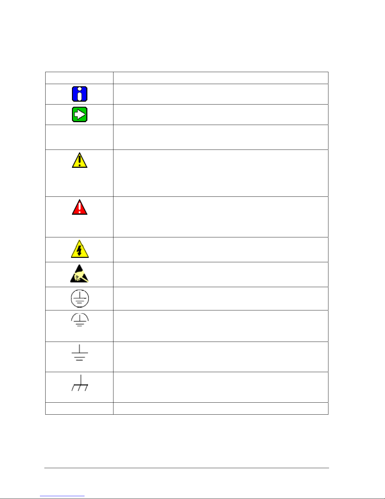
Symbol Descriptions and Definitions
The symbols identified and defined in the following table may appear in this document.
Symbol Definition
CAUTION
ATTENTION: Identifies information that requires special consideration.
TIP: Identifies advice or hints for the user, often in terms of performing a
Indicates a situation which, if not avoided, may result in equipment or work
(data) on the system being damaged or lost, or may result in the inability to
CAUTION: Indicates a potentially hazardous situation which, if not avoided,
may result in minor or moderate injury. It may also be used to alert against
CAUTION symbol on the equipment refers the user to the product manual for
additional information. The symbol appears next to required information in
WARNING: Indicates a potentially hazardous situation, which, if not avoided,
WARNING symbol on the equipment refers the user to the product manual
for additional information. The symbol appears next to required information
WARNING, Risk of electrical shock: Potential shock hazard where
HAZARDOUS LIVE voltages greater than 30 Vrms, 42.4 Vpeak, or 60 VDC
ESD HAZARD: Danger of an electro-static discharge to which equ i pment may
be sensitive. Observe precautions for handling electrostatic sensitive
Protective Earth (PE) terminal: Provided for connection of the protective
earth (green or green/yellow) supply system conductor.
Functional earth terminal: Used for non-safety purposes such as noise
immunity improvement. NOTE: This connection shall be bonded to
Protective Earth at the source of supply in accordance with national local
Earth Ground: Functional earth connection. NOTE: This connection shall be
bonded to Protective Earth at the source of supply in accordance with
national and local electrical code requirements.
properly operate the process.
could result in serious injury or death.
may be accessible.
electrical code requirements.
task.
unsafe practices.
the manual.
in the manual.
devices.
Chassis Ground: Identifies a connection to the chassis or frame of the
continued
equipment shall be bonded to Protective Earth at the source of supply in
Page vi ST 700 SmartLine Pressure Transmitters User’s Manual Revision 2.0
accordance with national and local electrical code requirements.
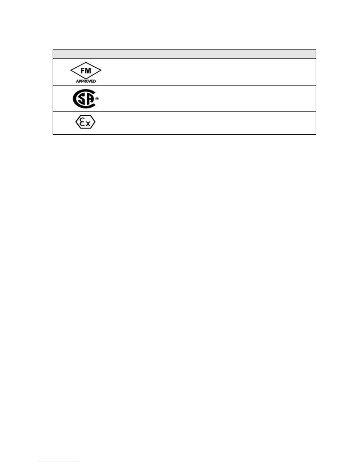
Symbol Description
®
The Factory Mutual
tested and certified to be reliable.
The Canadian Standards mark means the equipment has been tested and meets
applicable standards for safety and/or performance.
The Ex mark means the equipment complies with the requirements of the
European standards that are harmonised with the 94/9/EC Directive (ATEX
Directive, named after the French "ATmosphere EXplosible").
Approval mark means the equipment has been rigorously
Revision 2.0 ST 700 Smart Pressure Transmitter User’s Manual Page vii

Contents
1 Introduction .................................................................................................................................... 1
1.1 Overview ................................................................................................................................ 1
1.2 Features and Options .............................................................................................................. 1
1.2.1 Physical Characteristics ................................................................................................. 1
1.2.2 Functional Characteristics .............................................................................................. 2
1.3 ST 700 Transmitter Nameplate .............................................................................................. 3
1.4 Safety Certification Information ............................................................................................ 3
1.5 Transmitter Adjustments ........................................................................................................ 3
1.6 Display Options ..................................................................................................................... 4
1.7 Optional 3-Button Assembly ................................................................................................. 4
2 Application Design ........................................................................................................................ 5
2.1 Overview ................................................................................................................................ 5
2.1.1 Accuracy ........................................................................................................................ 5
2.1.2 Diagnostic Messages ...................................................................................................... 5
2.2 Safety ..................................................................................................................................... 6
2.2.1 Safety Integrity Level (SIL) ........................................................................................... 6
3 Installation and Startup .................................................................................................................. 7
3.1 Installation Site Evaluation .................................................................................................... 7
3.2 Honeywell MC Toolkit .......................................................................................................... 7
3.3 Display Installation Precautions ............................................................................................. 7
3.4 Mounting ST 700 SmartLine Pressure Transmitters .............................................................. 8
3.4.1 Summary ........................................................................................................................ 8
3.4.2 Mounting Di
3.4.3 Bracket Mounting Procedure ......................................................................................... 9
3.4.4 Mounting Transmitters with Small Absolute or Differential Pressure Spans .............. 11
3.4.5 Flange Mounting .......................................................................................................... 12
3.4.6 Remote Diaphragm Seal Mounting Information .......................................................... 13
3.5 Piping the ST 700 Transmitter ............................................................................................. 14
3.5.1 Piping Arrangements .................................................................................................... 14
3.5.2 Suggestions for Transmitter Location .......................................................................... 15
3.5.3 General Piping Guidelines ........................................................................................... 15
3.5.4 Procedure to Install Flange Adapters ........................................................................... 15
3.6 Wiring a Transmitter ............................................................................................................ 16
3.6.1 Overview ...................................................................................................................... 16
3.6.2 Digital System Integration Information ....................................................................... 18
3.6.3 Wiring Variations ......................................................................................................... 18
3.6.4 Wiring Procedure ......................................................................................................... 18
3.6.5 Lightning Protection .................................................................................................... 18
3.6.6 Supply Voltage Limiting Requirements ....................................................................... 18
3.6.7 Process Sealing ............................................................................................................ 19
3.6.8 Explosion-Proof Conduit Seal ..................................................................................... 19
3.7 Startup .................................................................................................................................. 19
3.7.1 Overview ...................................................................................................................... 19
3.7.2 Startup Tasks ................................................................................................................ 19
3.7.3 Output Check Procedures ............................................................................................. 20
3.7.4 Constant Current Source Mode Procedure
mensions
.................................................................................................... 8
...................................................................
20
Page viii ST 700 SmartLine Pressure Transmitters User’s Manual Revision 2.0

4 Operation ...................................................................................................................................... 22
4.1 Overview .............................................................................................................................. 22
4.2 Three-Button Operation ........................................................................................................ 22
4.2.1 The Basic Display Menu .............................................................................................. 23
4.2.2 Data Entry ..................................................................................................................... 27
4.2.3 Editing a Numeric value ............................................................................................... 27
4.2.4 Selecting a new setting from a list of choices .............................................................. 27
4.3 Three Button Operation with no Display Installed ............................................................... 28
4.3.1 Zero Adjustment ........................................................................................................... 28
4.3.2 Span Adjustment .......................................................................................................... 28
4.4 Changing the Default Failsafe Direction .............................................................................. 28
4.4.1 DE and Analog Differences .......................................................................................... 28
4.4.2 Procedure to Establish Failsafe Operation .................................................................... 29
4.5 Monitoring the Basic Display ............................................................................................... 32
4.5.1 Basic Display ................................................................................................................ 32
5 Maintenance ................................................................................................................................. 33
5.1 Overview .............................................................................................................................. 33
5.2 Preventive Maintenance Practices and Schedules ................................................................ 33
5.3 Inspecting and Cleaning Barrier Diaphragms ...................................................................... 33
5.4 Replacing the Communication Module ................................................................................ 36
5.5 Replacing the Meter Body .................................................................................................... 38
6 Calibration .................................................................................................................................... 42
6.1 Recommendations for Transmitter Calibration .................................................................... 42
6.2 Calibration Procedures
7 Troubleshoot
7.1 Overview .............................................................................................................................. 43
7.2 Critical Diagnostics Screens ................................................................................................. 43
7.2.1 Fault Conditions and Recommended Corrective Actions ............................................ 43
8 Parts List ....................................................................................................................................... 44
8 Parts List ....................................................................................................................................... 44
8.1 Overview .............................................................................................................................. 44
Appendix A. PRODUCT CERTIFICATIONS .................................................................................... 56
Index ..................................................................................................................................................... 68
ing ............................................................................................................................ 43
......................................................................................................... 42
Revision 2.0 ST 700 Smart Pressure Transmitter User’s Manual Page ix

List of Figures
Figure 1 – ST 700 Major Assemblies .................................................................................................... 2
Figure 2 – Electronics Housing Components ........................................................................................ 2
Figure 3 –Typical ST 700 Name Plate ................................................................................................... 3
Figure 4 – Typical Bracket Mounted and Flange Mounted Installations ............................................... 8
Figure 5 – Angle Mounting Bracket Secured to a Horizontal or Vertical Pipe ..................................... 9
Figure 6 – Inline Model Mounted to an Optional Bracket ................................................................... 10
Figure 7 – Rotating the Electronics Housing ....................................................................................... 10
Figure 8 – Using a Spirit Balance to Level a Transmitter .................................................................... 11
Figure 9 – Tank-Flange Mounted Transmitter ..................................................................................... 12
Figure 10 – Representative Remote Diaphragm Seal Transmitter Installation .................................... 13
Figure 11 – Typical 3-Valve Manifold with Blow-Down Piping ........................................................ 14
Figure 12 – Flange Adapter Removal and Replacement ..................................................................... 16
Figure 13 – Transmitter Operating Ranges .......................................................................................... 16
Figure 14 – Transmitter 3-Screw Terminal Board and Grounding Screw ........................................... 17
Figure 15 – Current Loop Test Connections ........................................................................................ 20
Figure 16 – Three-Button Option ......................................................................................................... 22
Figure 17 – Locating the Failsafe and Write Protect Jumpers ............................................................. 29
Figure 18 – Basic Display with Process Variable Format ................................................................... 32
Figure 19 – DP Transmitter Head Disassembly ................................................................................... 34
Figure 20 – Head Bolt Tightening Sequence ....................................................................................... 35
Figure 21 – PWA Replacement ........................................................................................................... 36
Figure 22 – Disassembly for Meter Body Replacement ...................................................................... 38
Figure 23 – Hardware Location to Remove the Meter Assembly ....................................................... 39
Figure 24 – Meter Body Reassembly ................................................................................................... 40
Figure 25 – Head Bolt Tightening Sequence ....................................................................................... 40
Figure 26 – Angle and Flat Bracket Parts ............................................................................................ 45
Figure 27 – Electronic Housing, Display End ..................................................................................... 47
Figure 28 – Electronic Housing, Terminal Block End ......................................................................... 48
Figure 29 – Transmitter Major Assemblies ......................................................................................... 49
Figure 30 - ST 700 Models STD710, 720, 730, & 770 ........................................................................ 51
Figure 31 – STG730, 740, 770, and STA722, 740 Transmitter Body (Ref.) ....................................... 53
Figure 32 – Inline Gauge and Inline Atmospheric Meter Body Bodies ............................................... 53
Page x ST 700 SmartLine Pressure Transmitters User’ s Manual Revision 2.0

List of Tables
Table 1 – Features and Options .............................................................................................................. 1
Table 2 – Available Display Characteristics .......................................................................................... 4
Table 3 – ST 700 Standard Diagnostics Messages ................................................................................. 5
Table 4 - Mounting Bracket procedure ..................................................................................................... 9
Table 5 – Flange Mounting Guidelines ................................................................................................ 13
Table 6 – Remote Diaphragm Mounting Details .................................................................................. 13
Table 7 – Suggested Connection Locations ......................................................................................... 15
Table 8 – Three-Button Option Functions ............................................................................................ 23
Table 9 – The Basic Display Menus ..................................................................................................... 23
Table 10 – Three-Button Data Entry .................................................................................................... 27
Table 11 – Hart and DE Failsafe and Write Protect Jumpers ............................................................... 30
Table 12 – Fieldbus Simulation and Write Protect Jumpers ................................................................ 30
Table 13 – Head Bolt Torque Values ................................................................................................... 35
Table 14 – Fault Conditions and Recommended Corrective Actions. ................................................. 43
Table 15 – Summary List of Recommended Spare Parts ..................................................................... 44
Table 16 – Angle and Flat Bracket Parts .............................................................................................. 4
Table 17 – Tr
Table 18 – S
Table 19 - I Parts for STG730, 740, 770 and STA722, 740 Transmitter Body .................................... 5
Table 20 - Inline Gauge and Inline Atmospheric Meter Body Parts .................................................... 53
Table 21 – Flange-Mounted Meter Body Parts (Ref Figure 32) .......................................................... 54
ansmitter Major Assemblies ........................................................................................... 4
T 700 Models STD710, 720, 730, 770 & STG774 (Ref. Figure 29) .............................. 50
6
7
2
Revision 2.0 ST 700 Smart Pressure Transmitter User’s Manual Page xi

Page xii ST 700 SmartLine Pressure Transmitters User’s Manual Revision 2.0

1 Introduction
1.1 Overview
This section is an introduction to the physical and functional characteristics Honeywell’s family of
ST 700 SmartLine Pressure Transmitters.
1.2 Features and Options
The ST 700 SmartLine Pressure Transmitter is available in a variety of models for measuring
Differential Pressure (DP), Gauge Pressure (GP), and Absolute Pressure (AP). Table 1 lists the
protocols, human interface (HMI), materials, approvals, and mounting bracket options for the ST 700.
Table 1 – Features and Options
Feature/Option Standard/Available Options
Communication Protocols HART version 7, Digitally Enhanced (DE), Fieldbus
Human-Machine Interface (HMI)
Options (Basic Display)
Calibration Single
Approvals (See Appendix C for details.) ATEX, CSA, FM, IECx, NEPSI
Mounting Brackets Angle/flat carbon steel/304 and 316 stainless steel, Marine
Integration Tools Experion
Basic Digital Display
Three-button programming (optional)
Basic display language: English only
304 stainless steel
1.2.1 Physical Characteristics
As shown in Figure 1, the ST 700 is packaged in two major assemblies: the Electronics Housing and
the Meter Body. The elements in the Electronic Housing respond to setup commands and execute the
software and protocol for the different pressure measurement types. Figure 2 shows the assemblies in
the Electronics Housing with available options.
The Meter Body provides connection to a process system. Several physical interface configurations
are available, as determined by the mounting and mechanical connections, all of which are described
in the “Installation” section of this manual.
Page iii ST 800 SmartLine Pressure Transmitters User’s Manual Revision 1.0
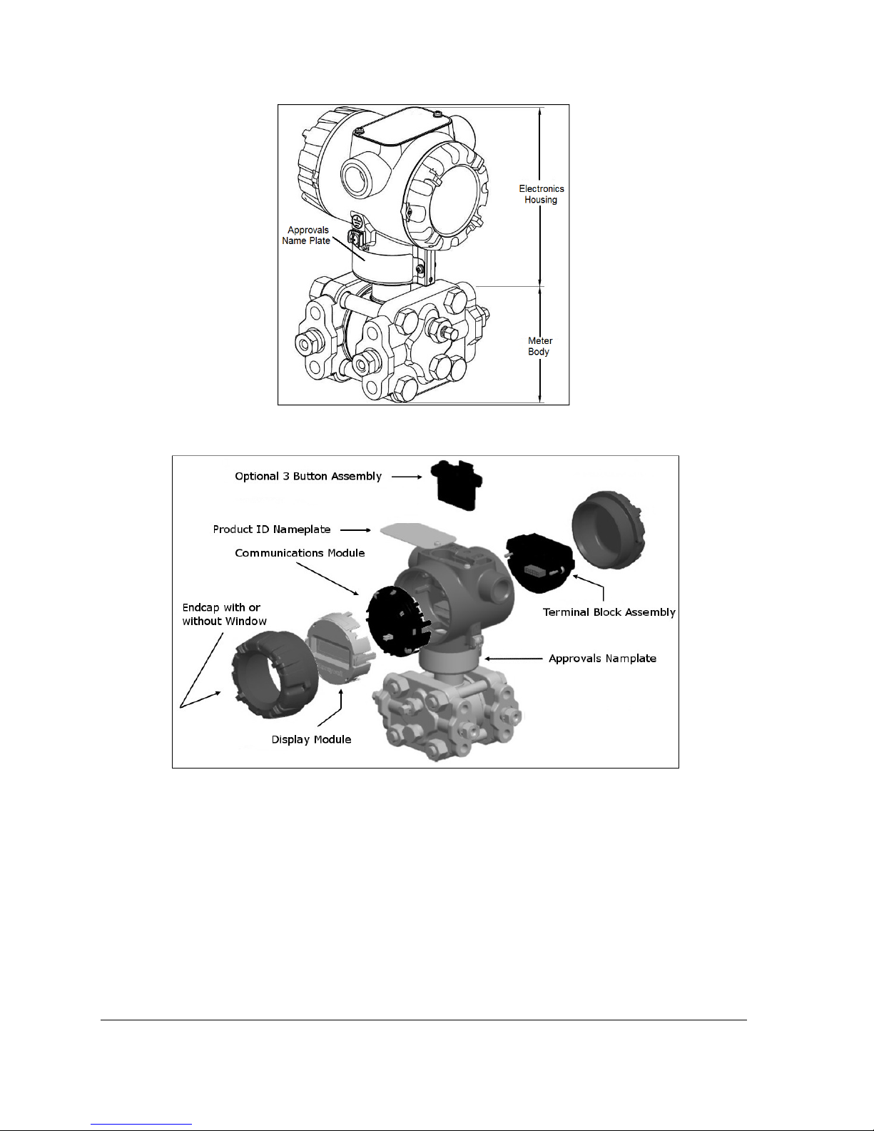
Figure 1 – ST 700 Major Assemblies
Figure 2 – Electronics Housing Components
1.2.2 Functional Characteristics
Functionally, the Transmitter can measure process pressure and provides a proportional analog 4 to
20 mA output to the measured process variable (PV). Available output communication protocols
include Honeywell Digitally Enhanced (DE), HART, and FOUNDATION Fieldbus.
An optional 3-button assembly is available to set up and make adjustments to the Transmitter. In
addition, a Honeywell Multi-Communication (MC) Toolkit (not supplied with the Transmitter) can
facilitate setup and adjustment procedures. Certain adjustments can be made through an Experion
Station or a Universal Station if the Transmitter is digitally integrated with Honeywell’s Experion or
TPS/TDC 3000 control system.
Page 72 ST 700 SmartLine Pressure Transmitters User’s Manual Revision 1.0
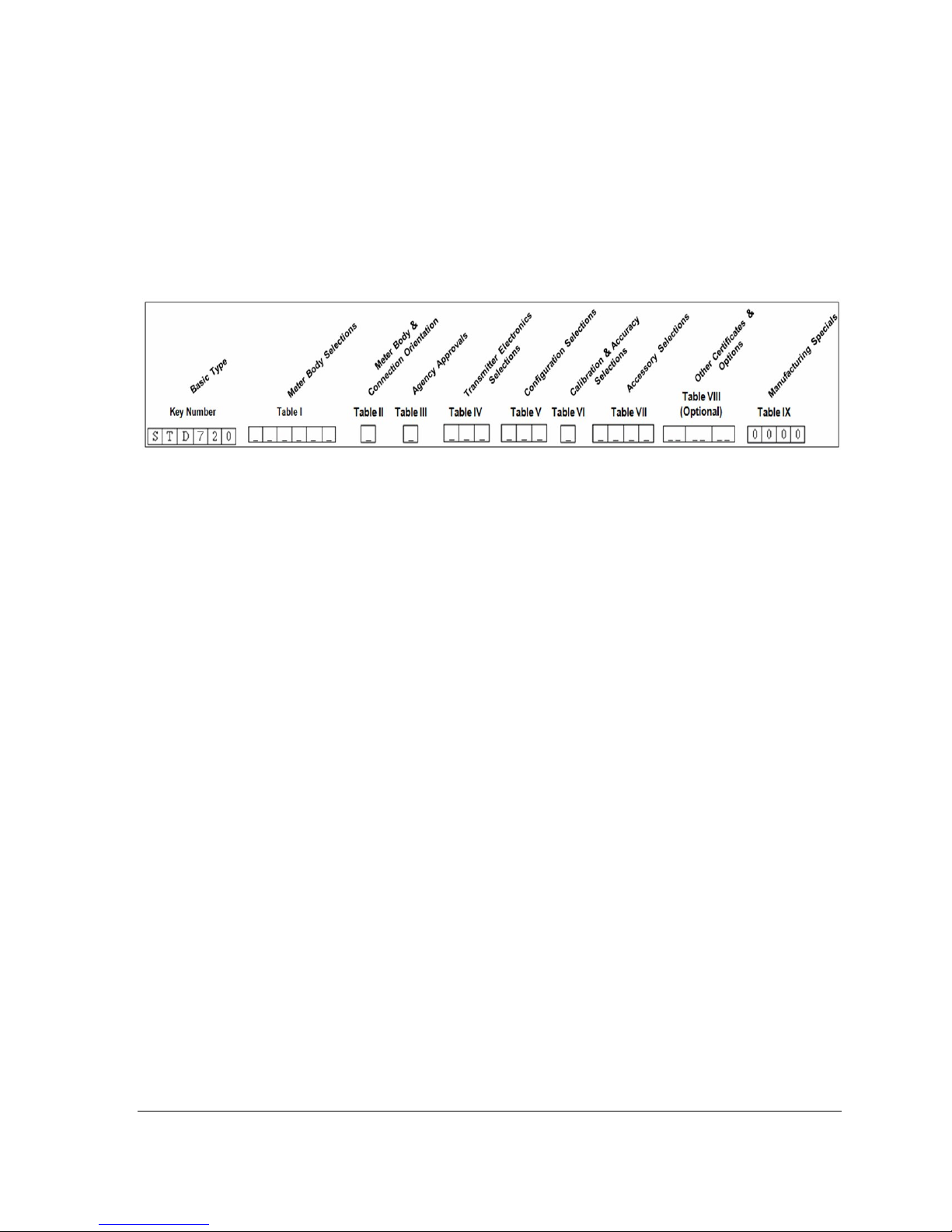
1.3 ST 700 Transmitter Nameplate
The Transmitter nameplate mounted on the bottom of the electronics housing (see Figure 1) lists its
model number, physical configuration, electronics options, accessories, certifications, and
manufacturing specialties. Figure 3 is an example of a typical Gauge Pressure (GP) or Atmospheric
Pressure (AP) Transmitter name plate. The model number format consists of a Key Number with
several table selections. The Differential Pressure (DP), Absolute Pressure (AP), and Gauge Pressure
(GP) name plates are essentially the same. However, the DP provides one additional entry (7 vs. 6) in
the Meter Body Selections (Table I) to accommodate the static pressure rating.
Figure 3 –Typical ST 700 Name Plate
You can readily identify the series and basic Transmitter type from the third and fourth digits in the
key number. The letter in the third digit represents one of these basic transmitter types:
• A = Absolute Pressure • D = Differential Pressure • F = Flange Mounted
• G = Gauge Pressure • R = Remote Seals
For a complete selection breakdown, refer to the appropriate Specification and Model Selection
Guide provided as a separate document.
1.4 Safety Certification Information
An “approvals” name plate is located on the bottom of the Electronics Assembly; see Figure 1for
exact location. The approvals name plate contains information and service marks that disclose the
Transmitter compliance information. Refer to Appendix C of this document for safety certification
requirements and details.
1.5 Transmitter Adjustments
Zero and Span adjustments are possible in ST 700 SmartLine Pressure Transmitters with the optional
three-button assembly located at the top of the Electronic Housing (see Figure 2).
You can also use the Honeywell MC Toolkit or other third-party hand-held zero to make any
adjustments to an ST 700 SmartLine Pressure Transmitter. Alternately, certain adjustments can be
made through the Experion or Universal Station, if the Transmitter is digitally integrated with a
Honeywell Experion or TPS system.
Revision 2.0 ST 700 Smart Pressure Transmitter User’s Manual Page 3

1.6 Display Options
The ST 700 SmartLine Pressure Transmitter with Basic Display.
Table 2 – Available Display Characteristics
Basic Display
• Suitable for basic process needs
• 360
• 2 lines, 16 characters
• Standard units-of-measurement: Pa, KPa, MPa, KGcm2, TORR, ATM, inH2O,
• Diagnostic messaging
• Square root output indications
o
rotation in 90o Increments
mH2O, bar, mbar, inHg, FTH2O, mmH2O, MMHG, & PSI
1.7 Optional 3-Button Assembly
The optional 3-Button Assembly provides the following features and capabilities:
• Increment, decrement, and enter key functions.
• With the menu-driven display:
o Comprehensive on-screen menu for navigation.
o Transmitter configuration.
o Transmitter calibration
o Display configuration.
o Set zero and span parameters.
Page 72 ST 700 SmartLine Pressure Transmitters User’s Manual Revision 1.0

2 Application Design
2.1 Overview
This section discusses the considerations involved with deploying a Honeywell ST 700 SmartLine
Pressure Transmitter in a process system. The following areas are covered:
• Safety
• Input and output data
• Reliability
• Environmental limits
• Installation considerations
• Operation and maintenance\
• Repair and replacement
2.1.1 Accuracy
The ST 700 SmartLine Pressure Transmitter (Transmitter) measures the gauge, differential, or
absolute pressure of a process and reports the measurement to a receiving device. Measurements are
accurate up to 0.05 of the calibrated span.
2.1.2 Diagnostic Messages
Transmitter standard diagnostics are reported in the two basic categories listed in Table 3. Problems
detected as critical diagnostics drive the analog output to the programmed burnout level. Problems
detected as non-critical diagnostics may affect performance without driving the analog output to the
programmed burnout level. Informational messages (not listed in Table 3) report various Transmitter
status or setting conditions. The messages listed in Table 3 are specific to the Transmitter, exclusive
of those associated with HART and DE protocols. HART and DE diagnostic messages are listed and
described in the ST 700 SmartLine Pressure Transmitter HART/DE Option User Manual, document
number 34-ST-25-47.
Table 3 – ST 700 Standard Diagnostics Messages
Critical Diagnostics
(Failure Conditions)
Sensor Comm Timeout
Meter Body Critical Failure
Electronic Module Diag Failure
Config Data Corrupt
Meter Body NVM Corrupt
Electronic Module DAC Failure
No DAC Compensation
No Factory Calibration
PV Out of Range
Fixed Current Mode
Sensor Over Temperature
Meter Body Excess Correct
No DAC Compensation
No Factory Calibration
Local Display
Low Supply Voltage
Non-Critical Diagnostics (Warning Conditions)
No DAC Calibration
Tamper Alarm
Meter Body Unreliable Comm
Loop Current Noise
AO Out of Range
URV Set Error – Span Config
Button
LRV Set Error – Span Config
Button
Revision 2.0 ST 700 Smart Pressure Transmitter User’s Manual Page 5

2.2 Safety
2.2.1 Safety Integrity Level (SIL)
The ST 700 is intended to achieve sufficient integrity against systematic errors by the manufacturer’s
design. A Safety Instrumented Function (SIF) designed with this product must not be used at a SIL
level higher than the statement, without “prior use” justification by the end user or diverse technology
redundancy in the design. Refer to the Honeywell SmartLine Safety Manual, 34-ST-25-37, for
additional information.
Page 72 ST 700 SmartLine Pressure Transmitters User’s Manual Revision 1.0

3 Installation and Startup
3.1 Installation Site Evaluation
Evaluate the site selected for the ST 700 Transmitter installation with respect to the process system
design specifications and Honeywell’s published performance characteristics for your particular
model. Some parameters that you may want to include in your site evaluation are:
• Environmental Conditions:
o Ambient Temperature
o Relative Humidity
• Potential Noise Sources:
o Radio Frequency Interference (RFI)
o Electromagnetic Interference (EMI)
• Vibration Sources
o Pumps
o Motorized System Devices (e.g., pumps)
o Valve Cavitation
• Process Parameters
o Temperature
o Maximum Pressure Rating
3.2 Honeywell MC Toolkit
In preparation for post-installation processes, refer to the MC Tookit User Manual, Document # 34-
ST-25-20, for battery conditioning and device operation and maintenance information.
3.3 Display Installation Precautions
Temperature extremes can affect display quality. The display can become unreadable at temperature
extremes; however, this is only a temporary condition. The display will again be readable when
temperatures return to within operable limits.
The display update rate may increase at cold temperature extremes, but as with readability, normal
updating resumes when temperatures are within limits for full operability.
Revision 2.0 ST 700 Smart Pressure Transmitter User’s Manual Page 7
3.4 Mounting ST 700 SmartLine Pressure Transmitters
3.4.1 Summary
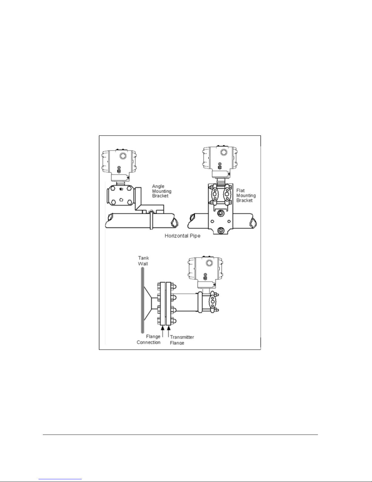
Transmitter models, except flush mounts and those with integral flanges, can be attached to a twoinch (50 millimeter) vertical or horizontal pipe using Honeywell’s optional angle or flat mounting
bracket; alternately you can use your own bracket. Flush-mount models are attached directly to a
process pipe or tank by a one-inch weld nipple. Models with integral flanges are supported by the
flange connection.
Figure 4 shows typical bracket-mounted and flange-mounted transmitter installations.
Figure 4 – Typical Bracket Mounted and Flange Mounted Installations
3.4.2 Mounting Dimensions
Refer to Honeywell drawing number 50049930 (Dual Head), 50049931 (In-Line), 50049932 (Flange
Mount) 50049933 (Extended Flange), and 50049934 (Remote Seal) for detailed dimensions.
Abbreviated overall dimensions are also shown on the Specification Sheets for the transmitter
models. This section assumes that the mounting dimensions have already been taken into account and
the mounting area can accommodate the Transmitter.
Page 72 ST 700 SmartLine Pressure Transmitters User’s Manual Revision 1.0
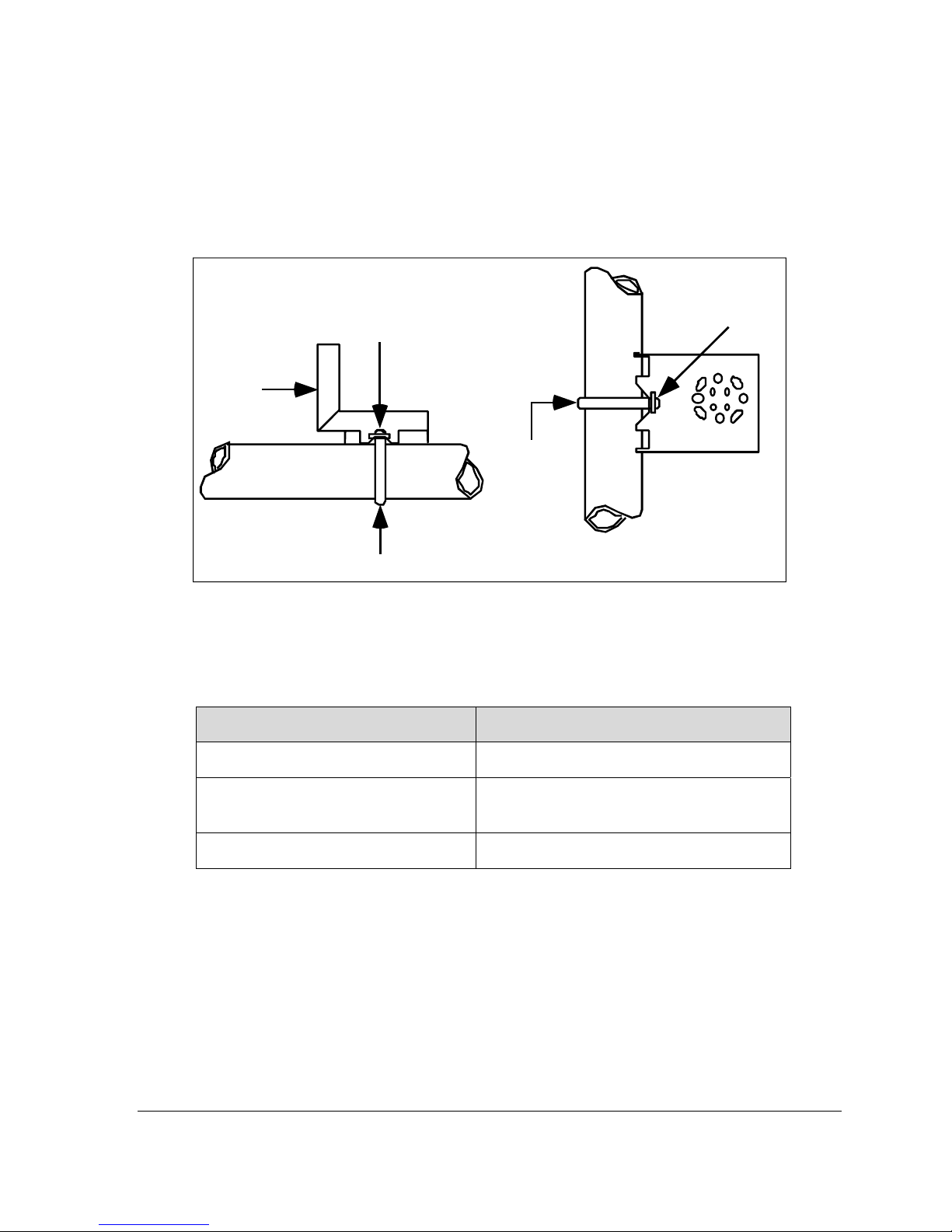
3.4.3 Bracket Mounting Procedure
If you are using an optional bracket, start with Step 1. For an existing bracket, start with Step 2.
1. Refer to Figure 5. Position the bracket on a 2-inch (50.8 mm) horizontal or vertical pipe, and
install a “U” bolt around the pipe and through the holes in the bracket. Secure the bracket
with the nuts and lock washers provided.
Nuts and
Lockwashers
Mounting
Bracket
U-Bolt
Nuts and
Lockwashers
Mounting
Bracket
Horizontal Pipe
Vertical P ipe
U-Bolt
Figure 5 – Angle Mounting Bracket Secured to a Horizontal or Vertical Pipe
2. Align the appropriate mounting holes in the Transmitter with the holes in the bracket. Use the
bolts and washers provided to secure the Transmitter to the bracket; see the following
variations.
Table 4 Mounting Bracket procedure
Transmitter Type Use Hardware
DP with double-ended process heads
and/or remote seals
In-line GP and AP (STGxxL and
STAxxL)
Dual-head GP and AP
EXAMPLE: Inline model mounted to an optional angle bracket. See Figure 6.
Alternate mounting holes in the ends of the
heads
The smaller “U” bolt provided to attach the
meter body to the bracket. See the
following example.
Mounting holes in the end of the process
head.
Revision 2.0 ST 700 Smart Pressure Transmitter User’s Manual Page 9
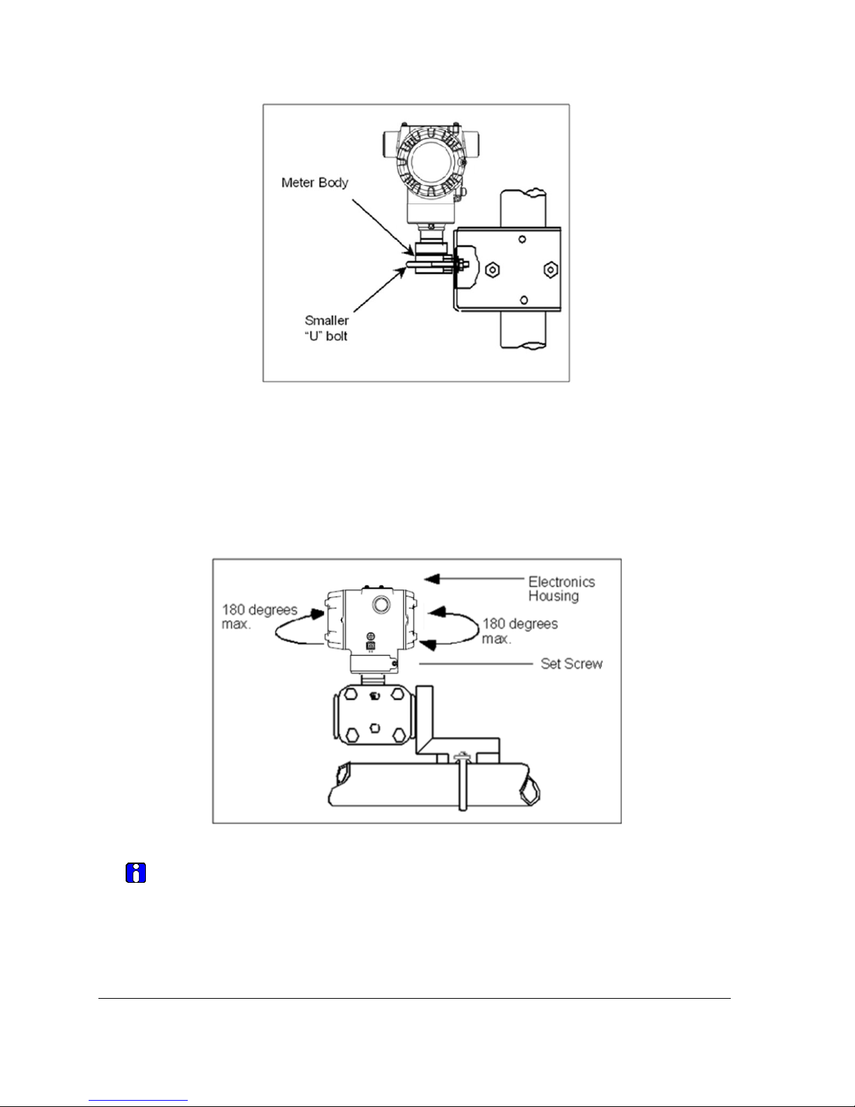
Figure 6 – Inline Model Mounted to an Optional Bracket
3. Loosen the set screw on the outside neck of the Transmitter one (1) full turn.
4. Rotate the Electronics housing a maximum of 180
o
left or right from the center to the position
you require, and tighten the set screw 8.9 to 9.7 pound-inches (1.40 to 1.68 Newton meters),
using a 4mm metric socket head wrench. See the following example and Figure 7.
EXAMPLE: Rotating the Electronics Housing
Figure 7 – Rotating the Electronics Housing
The mounting position of absolute pressure models STA822, STA82L, or a draft
range model STD810 is critical as the Transmitter spans become smaller.
A maximum zero shift of 2.5 mmHg for an Absolute Transmitter or 1.5 inches of
water (inH
that is rotated 90
O) for a Draft Range Transmitter can result from a mounting position
2
o
from the vertical. A typical zero-shift of 0.12 mmHg or 0.20 inH2O
can occur for a five (5)-degree rotation from the vertical.
Page 72 ST 700 SmartLine Pressure Transmitters User’s Manual Revision 1.0
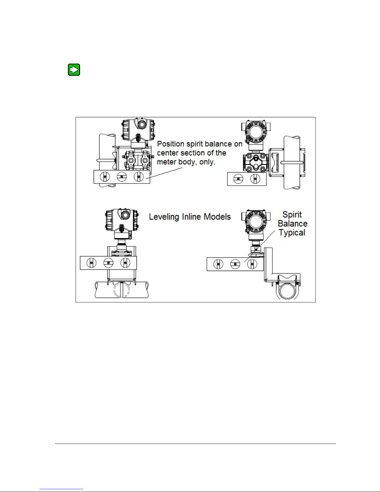
3.4.4 Mounting Transmitters with Small Absolute or Differential Pressure
Spans
To minimize positional effects on calibration (zero shift), take the appropriate
mounting precautions for the respective Transmitter model. For a model STA722 or
STA72L, ensure that the Transmitter is vertical when mounting it. You do this by
leveling the Transmitter side-to-side and front-to-back. Figure 8 shows how to level
a Transmitter using a spirit level.
Figure 8 – Using a Spirit Balance to Level a Transmitter
Revision 2.0 ST 700 Smart Pressure Transmitter User’s Manual Page 11
3.4.5 Flange Mounting
Figure 9 shows a typical tank-flange mount installation, with the Transmitter flange mounted to the
pipe on the wall of the tank.
On insulated tanks, remove enough insulaiton to accommodate the flange
extension.
When flange-mounting to a tank, note the following:
• The End User is responsible for providing a flange gasket and mounting hardware suitable for
the Transmitter service conditions.
• To avoid degrading performance in flush-mounted flanged Transmitters, exercise care to
ensure that the internal diameter of the flange gasket does not obstruct the sensing diaphragm.
• To prevent performance degradation in extended-mount flanged Transmitters, ensure that
sufficient clearance exists in front of the sensing diaphragm body.
Figure 9 – Tank-Flange Mounted Transmitter
Page 72 ST 700 SmartLine Pressure Transmitters User’s Manual Revision 1.0
3.4.6 Remote Diaphragm Seal Mounting Information
The combination of tank vacuum and high pressure capillary head effect should not
exceed nine (9) psi (300 mmHg) absolute. For insulated tanks, be sure to remove enough
insulation to accommodate the flange extension. The end user is responsible for supplying a
flange gasket and mounting hardware suitable for the service condition of the Transmitter.
Mount the Transmitter flanges within the limits in Table 5 for the fill fluid in the capillary
tubes, with a tank at one (1) atmosphere.
Table 5 – Flange Mounting Guidelines
Fill Fluid Mount the Flange…
Silicone 200 Oil <22 feet (6.7 meters) below the Transmitter
Chlorotrifluorethylene (CTFE) <11 feet (3.4 meters) below the Transmitter
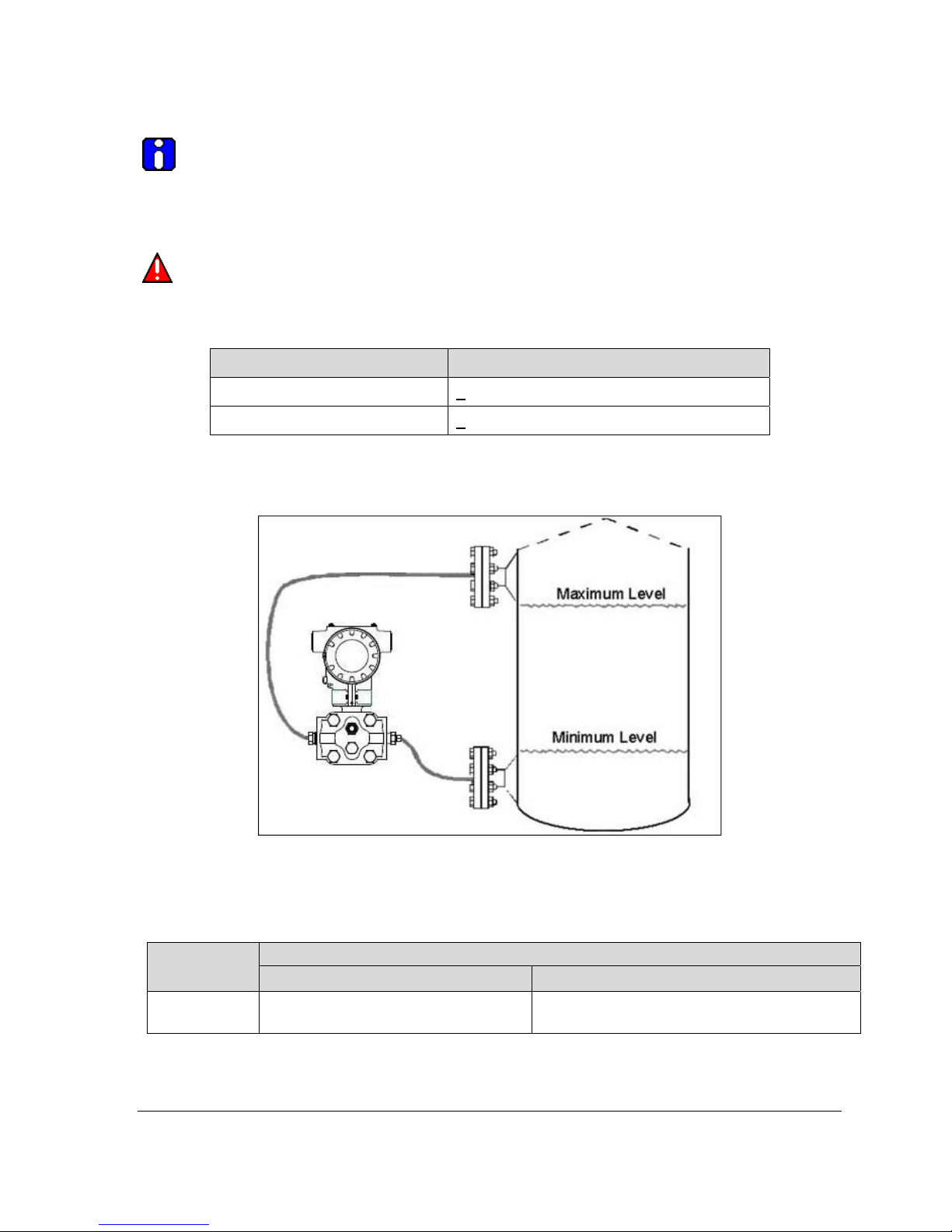
Refer to for a representative remote diaphragm seal installation. Mount the Transmitter at a remote
distance determined by the length of the capillary tubing.
Figure 10 – Representative Remote Diaphragm Seal Transmitter Installation
Depending on Transmitter model, connect the remote seal to the tank according to Table 6.
Transmitter
Model
STR73D
Transmitter High Pressure (HP) Side
to tank wall lower flange mounting.
Revision 2.0 ST 700 Smart Pressure Transmitter User’s Manual Page 13
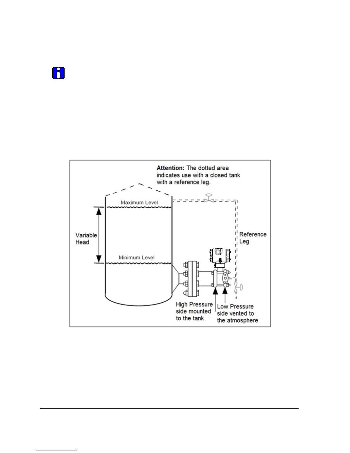
Table 6 – Remote Diaphragm Mounting Details
Connect the Remote Seal on ….
Variable Head Fixed or Constant Head
Transmitter Low Pressure (LP) side to tank
wall upper flange.
 Loading...