

Page 1
SmartLine
STA700 SmartLine Absolute Pressure
Specification 34-ST-03-120, Jan 2021
Technical Information
Introduction
Part of the SmartLine® family of products, the STA700 and
STA70L are suitable for monitoring, control and data
acquisition featuring piezoresistive sensor technology
combining pressure sensing with on chip temperature
compensation capabilities providing high accuracy, stability
and performance over a wide range of application
pressures and temperatures. The SmartLine family is also
fully tested and compliant with Experion ® PKS providing
the highest level of compatibility assurance and integration
capabilities. SmartLine easily meets the most demanding
application needs for pressure measurement applications.
Best in Class Features:
Accuracies up to 0.065% of span
Stability up to 0.020% of URL per year for 10 years
Automatic temperature compensation
Rangeability up to 100:1
Response times as fast as 100ms
Easy to use and intuitive display capabilities
Intuitive external zero, span, & configuration capability
Comprehensive on-board diagnostic capabilities
Integral Dual Seal design for safety based on
ANSI/NFPA 70-202 and ANSI/ISA 12.27.0
Full compliance to SIL 2/3 requirements
Modular design characters
Available with additional 4–year warranty
Communications/Output Options:
HART ® (version 7.0)
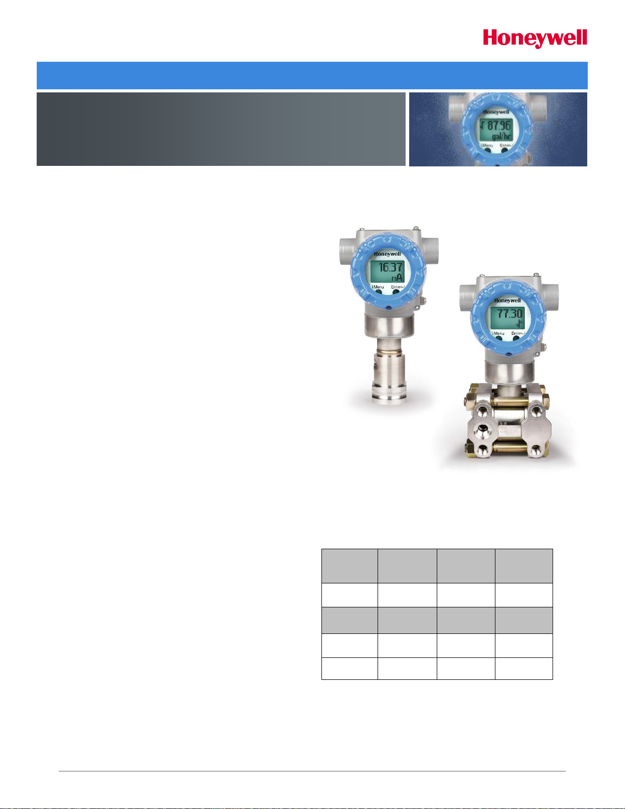
Figure 1 – STA700 InLine and Dual Head Absolute
Pressure Transmitters feature field-proven
piezoresistive sensor technology
Span & Range Limits:
Model
URL
mmHgA
(mbarA)
LRL
mmHgA
(mbarA)
Min Span
mm HgA
(mbarA)
STA725/72S
780 (1040)
0 (0)
50 (65.0)
Model
psia
(barA)
psi (barA)
psi (barA)
STA745/74S
500 (35)
0 (0)
5 (.35)
STA77S
3000 (210)
0 (0)
30 (2.1)
Page 2

2 STD700 Smart Pressure Transmitter
Description
The SmartLine family pressure transmitters are designed
around a high performance piezo-resistive sensor. This one
sensor actually integrates multiple sensors linking process
pressure measurement with on-board static pressure (DP
Models) and temperature compensation measurements.
Indication/Display Option
Standard LCD Display Features
o Modular (may be added or removed in the field)
o Supports HART protocol variant
o 0, 90,180, & 270 degree position adjustments
o Configurable (HART only) and standard (Pa, KPa,
MPa, KGcm2, Torr, ATM, inH2O, mH2O, bar, mbar,
inHG, FTH2O, mmH2O, mm HG, & psi) measurement
units.
o 2 Lines 6 digits PV (9.95H x 4.20W mm) 8 Characters
o Write protect Indication
o Built in Basic Device Configuration through Internal or
External Buttons – Range/Engineering Unit/Loop Test
/Loop Calibration/Zero /Span Setting
o Multiple language capabilities (EN, RU)
Diagnostics
SmartLine transmitters all offer digitally accessible
diagnostics which aid in providing advanced warning of
possible failure events minimizing unplanned shutdowns,
providing lower overall operational costs
System Integration
o SmartLine communications protocols all meet the most
current published standards for HART.
o All ST 700 units are Experion tested to provide the
highest level of compatibility assurance
Configuration Tools
External two button option for zero/span setting
Suitable for all electrical and environmental requirements,
SmartLine offers the ability to configure the transmitter and
display, for all basic parameters, via two externally
accessible buttons when a display option is
selected. Zero/span capabilities are also optionally available
via two external buttons with or without selection of the
display option.
Internal Two Button Configuration Option
The Standard display has two buttons that can be used for
Basic configuration such as re ranging, PV Engineering unit
setting, Zero/Span settings, Loop testing and calibration
functions
Hand Held Configuration
SmartLine transmitters feature two-way communication and
configuration capability between the operator and the
transmitter. All Honeywell transmitters are designed and
tested for compliance with the offered communication
protocols and are designed to operate with any Standards
compliant handheld configuration device.
Personal Computer Configuration
Field Device Manager (FDM) Software and FDM Express are
also available for managing HART device configurations.
Modular Design
To help contain maintenance & inventory costs, all ST 700
transmitters are modular in design supporting the user’s
ability to replace meter bodies, standard displays or
electronic modules without affecting overall performance.
Each meter body is uniquely characterized to provide intolerance performance over a wide range of application
variations in temperature and pressure.
Modular Features
Meter body replacement
Add or remove standard displays
Add or remove lightning protection (terminal
connection)
With no performance effects, Honeywell’s unique modularity
results in lower inventory needs and lower overall operating
costs.
Page 3
STA700 Smart Pressure Transmitter 3
Performance Specifications
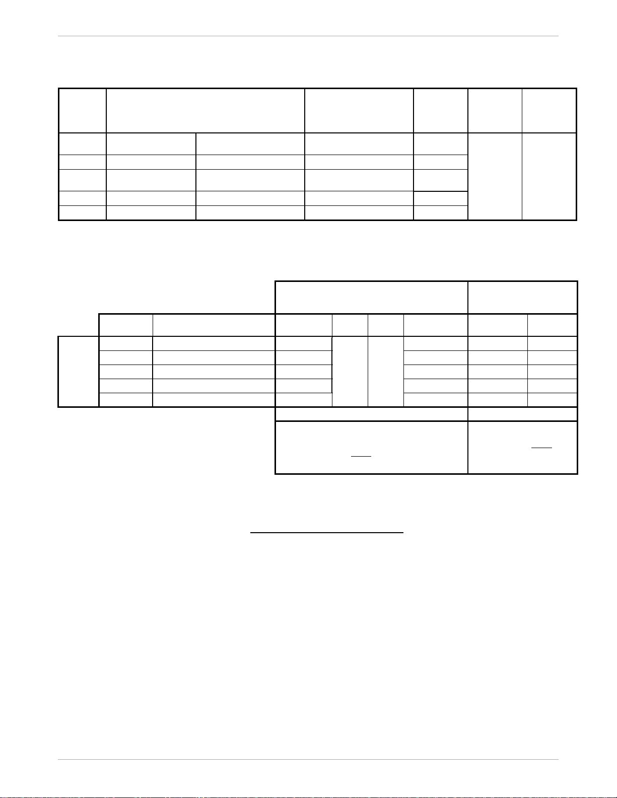
Reference Accuracy: (conformance to +/-3 Sigma)
Table 1
Model
URL
LRL
Min Span
Maximum
Turndown
Ratio
Stability
(% URL/Year
for 10 years)
Reference
Accuracy
1,2
% Span
Standard
STA725
780 mmHgA
(1040 mbarA)
0.0 mmHgA (0.0 mbarA)
50 mmHgA (65.0 mbarA)
15:1
0.02
0.065
STA745
500 psia (35 barA)
0.0 mmHgA (0.0 mbarA)
5 psia (0.35 barA)
100:1
STA72S
780 mmHgA
(1040 mbarA)
0.0 mmHgA (0.0 mbarA)
50 mmHgA (65.0 mbarA)
15:1
STA74S
500 psia (35 barA)
0.0 mmHgA (0.0 mbarA)
5 psia (0.35 barA)
100:1
STA77S
3000 psi (210 barA)
0.0 mmHgA (0.0 mbarA)
30 psia (2.1 barA)
100:1
Zero and span may be set anywhere within the listed (URL/LRL) range limits
Accuracy at Specified Span and Temperature: (Conformance to +/-3 Sigma)
Table 2
Accuracy
1,2
(% of Span)
Combined Zero & Span
temperature Effect
(% Span / 28oC(50oF)
Model
URL
Reference
Turndown
A
B
C
(see URL units)
D
E
Standard
Accuracy
STA725
780 mmHgA (1040 mbarA)
6.5:1
0.005
0.060
120 (160)
0.075
0.060
STA745
500 psia (35 barA)
16.7:1
30 (2.07)
0.075
0.015
STA72S
780 mmHgA (1040 mbarA)
4.3:1
180 (240)
0.075
0.120
STA74S
500 psia (35 barA)
16.7:1
30 (2.07)
0.075
0.020
STA77S
3000 psi (210 barA)
5:1
600 (41.37)
0.075
0.015
Turn Down Effect
Temp Effect
Total Performance (% of Span):
Total Performance Calculation: = +/- √ (Accuracy)2 + (Temperature Effect)2
Total Performance Examples (for comparison): (standard accuracy, 5:1 Turndown, +/-50 oF (28oC) shift)
STA725 @ 156 mmHgA: 0.381% of span STA72S @ 156 mmHgA: 0.679% of span
STA745 @ 100 psia: 0.163% of span STA74S @ 100 psia: 0.187% of span
STA77S @ 600 psia: 0.163% of span
Typical Calibration Frequency:
Calibration verification is recommended every two (2) years
Notes:
1. Terminal Based Accuracy - Includes combined effects of linearity, hysteresis, and repeatability. Analog output adds 0 .006% of span.
2. For zero based spans and reference conditions of: 25oC (77oF), 10 to 55% RH, and 316 Stainless Steel barrier diaphragm.
Page 4
4 STA700 Smart Pressure Transmitter
Operating Conditions – All Models
Parameter
Reference
Condition
Rated Condition
Operative Limits
Transportation and
Storage
C
F
C
F
C
F
C
F
Ambient Temperature1
25±1
77±2
-40 to 85
-40 to 185
-40 to 85
-40 to 185
-55 to 120
-67 to 248
Meter Body Temperature
STA725 / STA72S
25±1
77±2
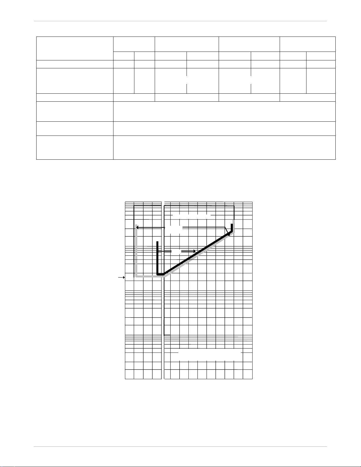
See Figure 2
See Figure 2
-55 to 125
-67 to 257
STA745, 74S, 77S
25±1
77±2
-40 to 110
-40 to 230
-40 to 125
-40 to 257
-55 to 125
-67 to 257
Humidity %RH
10 to 55
0 to 100
0 to 100
0 to 100
Vacuum Region - Minimum
Pressure
STA725, 72S, 745, 74S, 77S
See Figure 2.
Operate within specifications above 25 mmHgA (33 mbarA). Short term2 exposure to full
vacuum will not result in damage.
Supply Voltage, Current,
and Load Resistance
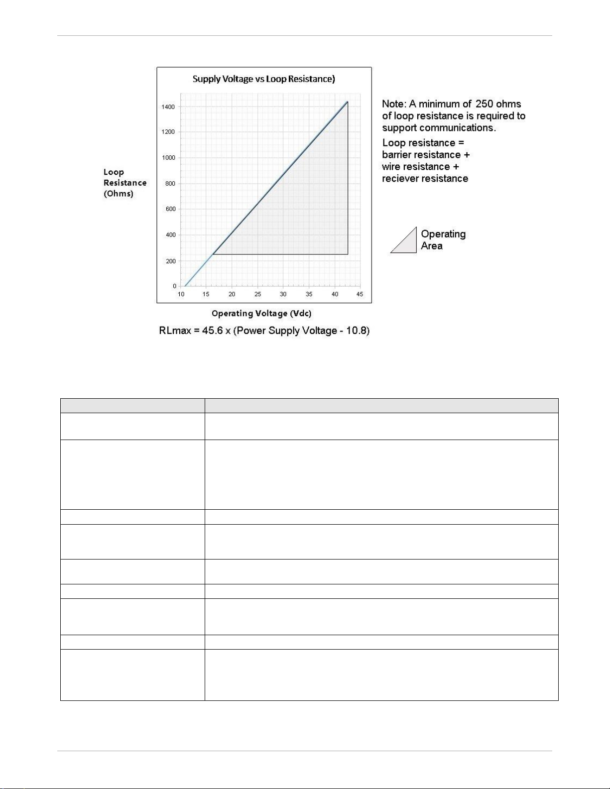
10.8 to 42.4 Vdc at terminals (IS versions limited to 30 Vdc)
0 to 1,440 ohms (as shown in Figure 3)
Maximum Allowable
Working Pressure
(MAWP) 3, 4
STA725, 72S = 780 mmHgA (1,040 mbarA)
STA745, 74S = 500 psia (35 barA)
STA77S = 3,000 psia (210 barA)
1
LCD Display operating temperature -20C to +70C Storage temperature -30C to 80C.
2
Short term equals 2 hours at 70C (158F).
3
Units can withstand overpressure of 1.5 x MAWP without damage.
4
Consult factory for MAWP of ST 700 transmitters with CRN approval.
5
Silicone minimum temperature rating is -40C (-40F). CTFE minimum temperature rating is -30C (-22F).
Figure 2 - Measured pressure versus meter body temperature chart for ST 700 Dual Head and Inline
models
-40
-30
-20
40
50
60
70
80
90
100
110
120
ºC
ºF
-40
-22
-4
104
122
140
158
176
194
212
230
248
0.1
1.0
10
100
1000
2
3 4 5 6 7 8 9 2 3 4 5
6
7 8 9
2 3 4 5 6
7 8 9
2
3 4 5 6 7 8 9
] [
] [
] [
Meter Body Temperature
] [
NOTE:
Short term exposure (2 hours at
70°C/158°F) to hard vacuum will not
result in damage.
0
32
Measured
Pressure
mmHgA
Rated Operating Area
Silicone Oil
200®
Operative
Limit
CTFE
25 mmHgA
(33.3 mbarA)
23065
Page 5
STA700 Smart Pressure Transmitter 5
Figure 3 - Supply voltage and loop resistance chart & calculations
Performance Under Rated Conditions – All Models
Parameter
Description
Analog Output
Digital Communications:
Two-wire, 4 to 20 mA
HART 7 protocol
HART Output Failure Modes
Honeywell Standard: NAMUR NE 43
Compliance:
Normal Limits: 3.8 – 20.8 mA 3.8 – 20.5
mA
Failure Mode: ≤ 3.6 mA and ≥ 21.0 mA ≤ 3.6 mA and ≥
21.0 mA
Supply Voltage Effect
0.005% of span per volt.
Transmitter Turn on Time
(includes power up & test
algorithms)
2.5 sec
Response Time
(delay + time constant)
100ms
Damping Time Constant
Adjustable from 0 to 32 seconds in 0.1 increments. Default Value: 0.5 seconds
Vibration Effect
Less than +/- 0.1% of URL w/o damping
Per IEC60770-1 field or pipeline, high vibration level (10-2000Hz: 0.21
displacement/3g max acceleration)
Electromagnetic Compatibility
Meets IEC61326-3-1
Lightning Protection Option
Leakage Current: 10uA max @ 42.4VDC 93C
Impulse rating:
8/20uS 5000A (>10 strikes) 10000A (1 strike min.)
10/1000uS 200A (> 300 strikes)
Page 6

6 STA700 Smart Pressure Transmitter
Materials Specifications (see model selection guide for availability/restrictions with various models)
Parameter
Description
Barrier Diaphragms Material
STA7x5 Dual Head: 316L SS, Hastelloy® C-2762
STA7xS Inline: 316L SS, Hastelloy C-2762
Process Head Material
STA700 Dual Head: Carbon Steel (Zinc Plated)5, 316 SS4, Hastelloy® C-276
6
STA700 Inline: 316L SS4, Hastelloy® C-2766
Vent/Drain Valves & Plugs
1
STA700 Dual Head:316 SS4, Hastelloy® C-276
2
STA700 Inline: N/A
Head Gaskets
STA700 Dual Head: Glass-filled PTFE standard. Viton® and graphite are optional.
STA700 Inline: N/A
Meter Body Bolting
STA700 Dual Head: Carbon Steel (Zinc plated) standard. Options include 316 SS,
NACE A286 SS bolts and nuts or NACE A286 SS bolts nuts and Super Duplex
STA700 Inline: N/A
Mounting Bracket
Carbon Steel (Zinc-plated) or 304 or 316 Stainless Steel. See Figures 4 & 5
Fill Fluid
Silicone 200, CTFE (Chlorotrifluoroethylene)
Electronic Housing
Pure Polyester Powder Coated Low Copper (<0.4%)-Aluminum. Meets NEMA 4X,
IP66, IP67 and NEMA 7 (explosion proof). All stainless steel housing is optional.
Process Connections
STA700 Dual Head: ½ -inch NPT (female)
STA700 Inline: ½ -inch NPT (female), ½ -inch NPT male, 9/16 Aminco. G½ -B Male
Thread
Wiring
Accepts up to 16 AWG (1.5 mm diameter).
Dimensions
See Figure 4 and Figure 5
Net Weight
STA700 Dual Head: 8.3 pounds (3.8 Kg). STA700 InLine: 3.6 pounds (1.6 Kg) with
Aluminum Housing
1
Vent/Drains are sealed with Teflon®
2
Hastelloy
®
C-276 or UNS N10276
4
Supplied as 316 SS or as Grade CF8M, the casting equivalent of 316 SS.
5
Carbon Steel heads are zinc-plated and not recommended for water service due to hydrogen migration. For that service, use 316 stainless steel wetted
Process Heads.
6
Hastelloy
®
C-276 or UNS N10276. Supplied as indicated or as Grade CW12MW, the casting equivalent of Hastelloy® C-276
Page 7

STA700 Smart Pressure Transmitter 7
Communications Protocols & Diagnostics
HART Protocol
Version:
HART 7
Power Supply
Voltage: 10.8 to 42.4 Vdc at terminals
Load: Maximum 1440 ohms See Figure 3
Minimum Load: 0 ohms. (For handheld communications a minimum load of 250 ohms is required)
Standard Diagnostics
ST 700 top level diagnostics are reported as either critical or non-critical and readable via the DD/DTM tools or integral
display as shown below.
Critical Diagnostics
HART DD/DTM Tools
Standard Display
Electronic Module DAC
Failure
Fault Comm El
Meter Body NVM Corrupt
Fault Mtrbody
Config. Data Corrupt
Fault Comm El
Electronic Module Diag
Failure
Fault Comm El
Meter Body Critical Failure
Fault Mtrbody
Sensor Comms Timeout
Fault Mbd Com
Non-Critical Diagnostics
HART DD/DTM Tools
Display Failure
Electronic Module Comm Failure
Meter Body Excess Correct
Sensor Over Temperature
Fixed Current Mode
PV Out of Range
No Factory Calibration
LRV Set Error – Zero Config. Button
URV Set Error – Zero Config. Button
AO Out of Range
Loop Current Noise
Meter Body Unreliable Comm
No DAC Calibration
Sensor Supply Voltage Low
Refer to ST 700 diagnostics tech note for additional level diagnostic information.
Page 8

8 STA700 Smart Pressure Transmitter
Hazardous Area Certifications:
MSG
CODE
AGENCY
TYPE OF PROTECTION
COMM.
OPTION
ELECTRICAL
PARAMETERS
AMBIENT TEMP
(Ta)
A
FM
Approvals
TM
USA
Explosionproof:
Class I, Division 1, Groups A, B, C, D;
Dust Ignition Proof:
Class II, III, Division 1, Groups E, F, G;
T6..T5
Class l, Zone 0/1, AEx db IIC T6..T5 Ga/Gb
Class ll, Zone 21, AEx tb IIIC T95o Db
All
Note 1
T5: -50 ºC to 85ºC
T6: -50 ºC to 65ºC
Intrinsically Safe:
Class I, II, III, Division 1, Groups A, B, C, D,
E, F, G: T4
Class l, Zone 0, AEx ia IIC T4 Ga
FISCO Field Device (Only for FF Option)
Ex ia IIC T4 Ga; Ex ic IIC T4 Gc
4-20 mA /
DE/ HART
Note 2a
-50 ºC to 70ºC
Foundation
Fieldbus
Note 2b
-50 ºC to 70ºC
Nonincendive:
Class I, Division 2, Groups A, B, C, D
locations, T4
Class l, Zone 2, AEx nA IIC T4 Gc
4-20 mA /
DE/ HART/
Foundation
Fieldbus
Note 1
-50 ºC to 85ºC
Enclosure: Type 4X/ IP66/ IP67
All
All
-
STANDARDS: FM Class 3600:2011; FM Class 3610: 2010; FM Class 3611: 2004; FM Class
3615: 2006; FM Class 3616: 2011; FM Class 3810: 2005; ANSI/ISA 60079-0: 2013; ANSI/UL
60079-1: 2015; ANSI/UL 60079-11: 2014; ANSI/ISA 60079-15: 2012; ANSI/UL 60079-26: 2017;
ANSI/UL 60079-31: 2015; ANSI/NEMA 250: 2003; ANSI/ IEC 60529: 2004
B
Canadian
Standards
Association
(CSA)
USA and
Canada
Explosion Proof:
Class I, Division 1, Groups A, B, C, D;
Class II, Division 1, Groups E, F, G;
Class III, Division 1, T6..T5
Class I Zone 1 AEx db IIC T6..T5 Ga/Gb
Ex db IIC T6..T5 Ga/Gb
Zone 22 AEx tb IIIC T95o Db
Ex tb IIIC T95o Db
All
Note 1
T5: -50oC TO 85oC
T6: -50oC TO 65oC
Intrinsically Safe:
Class I, II, III, Division 1, Groups A, B, C, D;
Class II, Division 1, Groups E, F, G;
Class III, Division 1, T4
Class I Zone 0, AEx ia IIC T4 Ga
Class I Zone 2, AEx ic IIC T4 Gc
Ex ia IIC T4 Ga
Ex ic IIC T4 Gc
FISCO Field Device (Only for FF Option)
Ex ia IIC T4 Ga;
Ex ic IIC T4 Gc
4-20 mA /
DE/ HART
Note 2
-50oC TO 70oC
Foundation
Fieldbus
Note 2
-50oC TO 70oC
Nonincendive:
Class I, Division 2, Groups A, B, C, D;
Class II, Division 2, Groups F, G;
Class III, Division 2, T4
Class I Zone 2 AEx nA IIC T4 Gc
Ex nA IIC T4 Gc
4-20 mA /
DE/ HART/
Foundation
Fieldbus
Note 1
-50oC to 85oC
Enclosure: Type 4X/ IP66/ IP67
All
All
-
Page 9

STA700 Smart Pressure Transmitter 9
MSG
CODE
AGENCY
TYPE OF PROTECTION
COMM.
OPTION
ELECTRICAL
PARAMETERS
AMBIENT TEMP
(Ta)
STANDARDS: CSA C22.2 No. 0-10; CSA C22.2 No. 94-M91; CSA C22.2 No. 25-1966; CSA C22.2
No. 30-M1986; CSA C22.2 No. 142-M1987; CSA C22.2 No. 157-92; CSA C22.2 No. 213-M1987;
CSA-C22.2 No. 60529:05; CSA-C22.2 No. 60079-0:11; CSA-C22.2 No. 60079-1:11; CSA-C22.2
No. 60079-11:11; CSA-C22.2 No. 60079-15:12; CSA-C22.2 No. 60079-31:12; ISA 12.12.012010; ISA 60079-0: 2009; ISA 60079-11: 2011; ISA 60079-15: 2009; ISA 60079-26: 2008; ISA60079-27:2007 (12.02.04)-2006 (R2011); UL 913 Ed. 6; UL 916:1998; ANSI/ISA-12.27.01-2011
C
ATEX
Flameproof: SIRA 12ATEX2233X
II 1/2 G Ex db IIC T6..T5 Ga/Gb
II 2 D Ex tb IIIC T95oC…T120oC Db
All
Note 1
T5: -50oC TO 85oC
T6: -50oC TO 65oC
Intrinsically Safe: SIRA 12ATEX2233X
II 1 G Ex ia IIC T4 Ga
FISCO Field Device (Only for FF Option)
II 1 G Ex ia IIC T4 Ga
4-20 mA / DE/
HART
Note 2
-50oC TO 70oC
Foundation
Fieldbus
Note 2
-50oC TO 70oC
Zone 2, Increase Safety: SIRA
12ATEX4234X
II 3 G Ex ec IIC T4 Gc
4-20 mA / DE/
HART/
Note 1
-50oC TO 85oC
Zone 2, Intrinsically Safe: SIRA
12ATEX4234X
II 3 G Ex ic IIC T4 Gc
FISCO Field Device (Only for FF Option)
II 3 G Ex ic IIC T4 Gc
4-20 mA / DE/
HART/
Foundation
Fieldbus
Note 2
-50oC TO 85oC
Enclosure: IP66/ IP67
All
All
-
STANDARDS: EN 60079-0: 2012/A11: 2013; EN 60079-1: 2014; EN 60079-7: 2015; EN 6007911: 2012; EN 60079-26: 2015; EN 60079-31: 2009
D
IECEx
World
Flameproof: IECEx SIR 12.0100X
Ex db IIC T6..T5 Ga/Gb
Ex tb IIIC T95oC…T120oC Db
All
Note 1
T5: -50oC TO 85oC
T6: -50oC TO 65oC
Intrinsically Safe: IECEx SIR 12.0100X
Ex ia IIC T4 Ga
FISCO Field Device (Only for FF Option)
Ex ia IIC T4 Ga; Ex ic IIC T4 Gc
4-20 mA / DE/
HART
Note 2
-50oC TO 70oC
Foundation
Fieldbus
Note 2
-50oC TO 70oC
Zone 2, Increase Safety: IECEx SIR
12.0100X
Ex ec IIC T4 Gc
4-20 mA / DE/
HART/
Foundation
Fieldbus
Note 1
-50oC TO 85oC
Zone 2, Intrinsically Safe: IECEx SIR
12.0100X
Ex ic IIC T4 Gc
FISCO Field Device (Only for FF Option)
Ex ic IIC T4 Gc
4-20 mA / DE/
HART/
Foundation
Fieldbus
Note 2
-50oC TO 85oC
Enclosure: IP66/ IP67
All
All
-
STANDARDS: IEC 60079-0: 2011; IEC 60079-1: 2014; IEC 60079-7: 2017; IEC 60079-11: 2011;
IEC 60079-26: 2014; IEC 60079-31: 2013
Page 10

10 STA700 Smart Pressure Transmitter
E
SAEx
South Africa
Flameproof :
Ex d IIC T6…T5 Ga/Gb
Ex tb IIIC T95oC…T120oC Db
All
Note 1
T5: -50oC TO 85oC
T6: -50oC TO 65oC
Intrinsically Safe:
Ex ia IIC Ga T4
FISCO Field Device (Only for FF Option)
Ex ia IIC T4 Ga; Ex ic IIC T4 Gc
4-20 mA / DE/
HART
Note 2
-50oC TO 70oC
Foundation
Fieldbus
Note 2
-50oC TO 70oC
Zone 2, Increase Safety:
II 3 G Ex ec IIC T4 Gc
4-20 mA / DE/
HART/
Foundation
Fieldbus
Note 1
-50oC TO 85oC
Zone 2, Intrinsically Safe:
Ex ic IIC T4 Gc
FISCO Field Device (Only for FF Option)
Ex ic IIC T4 Gc
4-20 mA / DE/
HART/
Foundation
Fieldbus
Note 2
-50oC TO 85oC
Enclosure: IP66/ IP67
All
All
-
F
INMETRO
Brazil
Flameproof:
Ex db IIC T6..T5 Ga/Gb
Ex tb IIIC T95oC…T120oC Db
All
Note 1
T5: -50oC TO 85oC
T6: -50oC TO 65oC
Intrinsically Safe:
Ex ia IIC T4 Ga
FISCO Field Device (Only for FF Option)
Ex ia IIC T4 Ga; Ex ic IIC T4 Gc
4-20 mA / DE/
HART
Note 2a
-50oC TO 70oC
Foundation
Fieldbus
Note 2b
-50oC TO 70oC
Zone 2, Increase Safety:
II 3 G Ex ec IIC T4 Gc
4-20 mA / DE/
HART/
Foundation
Fieldbus
Note 1
-50oC TO 85oC
Zone 2, Intrinsically Safe:
Ex ic IIC T4 Gc
FISCO Field Device (Only for FF Option)
Ex ic IIC T4 Gc
4-20 mA / DE/
HART/
Foundation
Fieldbus
Note 2
-50oC TO 85oC
Enclosure : IP 66/67
All
All
-
G
NEPSI
CHINA
Flameproof:
Ex db IIC T6..T5 Ga/Gb
Ex tb IIIC T 95oC Db
All
Note 1
T5: -50oC TO 85oC
T6: -50oC TO 65oC
Intrinsically Safe:
Ex ia IIC T4 Ga
FISCO Field Device (Only for FF Option)
Ex ia IIC T4 Ga; Ex ic IIC T4 Gc
4-20 mA / DE/
HART
Note 2
-50oC TO 70oC
Foundation
Fieldbus
Note 2
-50oC TO 70oC
Zone 2, Increase Safety:
II 3 G Ex ec IIC T4 Gc
4-20 mA / DE/
HART/
Foundation
Fieldbus
Note 1
-50oC TO 85oC
Zone 2, Intrinsically Safe:
Ex ic IIC T4 Gc
FISCO Field Device (Only for FF Option)
Ex ic IIC T4 Gc
4-20 mA / DE/
HART/
Foundation
Fieldbus
Note 2
-50oC TO 85oC
Enclosure : IP 66/67
All
All
-
Page 11

STA700 Smart Pressure Transmitter 11
I
EAC
Russia, Belarus
and
Kazakhstan
Flameproof:
Ga/Gb Ex d IIC T6..T5
Ex tb IIIC Db T 85oC
All
Note 1
T5: -50oC TO 85oC
T6: -50oC TO 65oC
Intrinsically Safe:
Ga Ex ia IIC T4 X
FISCO Field Device
(Only for FF Option)
Ga Ex ia IIC T4 X
4-20 mA /
DE/ HART
Note 2
-50oC TO 70oC
Foundation
Fieldbus
Note 2
-50oC TO 70oC
Zone 2, Non Sparking:
2 Ex nA IIC T4 Gc X
4-20 mA /
DE/ HART/
Foundation
Fieldbus
Note 1
-50oC TO 85oC
Zone 2, Intrinsically Safe:
Ga Ex ic IIC T4 X
FISCO Field Device
(Only for FF Option)
2 Ex ic IIC T4 Gc X
4-20 mA /
DE/ HART/
Foundation
Fieldbus
Note 2
-50oC TO 85oC
Enclosure : IP 66/67
All
All
J
CCoE
INDIA
Flameproof:
Ex d IIC T6..T5 Ga/Gb
All
Note 1
T5: -50oC TO 85oC
T6: -50oC TO 65oC
Intrinsically Safe:
Ex ia IIC T4 Ga
FISCO Field Device (Only for FF Option)
Ex ia IIC T4 Ga; Ex ic IIC T4 Gc
4-20 mA / DE/
HART
Note 2
-50oC TO 70oC
Foundation
Fieldbus
Note 2
-50oC TO 70oC
Non Sparking
Ex nA IIC T4 Gc
4-20 mA / DE/
HART/
Foundation
Fieldbus
Note 1
-50oC TO 85oC
Enclosure: IP66/ IP67
All
All
-
K
UATR
UKRAINE
Flameproof:
II 1/2 G Ex db IIC T6..T5 Ga/Gb
II 2 D Ex tb IIIC T95oC…T120oC Db
All
Note 1
T5: -50oC TO 85oC
T6: -50oC TO 65oC
Intrinsically Safe:
II 1 G Ex ia IIC T4 Ga
FISCO Field Device (Only for FF Option)
II 1 G Ex ia IIC T4 Ga
4-20 mA / DE/
HART
Note 2
-50oC TO 70oC
Foundation
Fieldbus
Note 2
-50oC TO 70oC
Enclosure: IP66/ IP67
All
All
-
Page 12

12 STA700 Smart Pressure Transmitter
Notes:
1. Operating Parameters:
Voltage= 11 to 42 V DC
Current= 4-20 mA Normal
2. Intrinsically Safe Entity Parameters
a. Analog/ DE/ HART Entity Values:
Vmax= Ui = 30V
Imax= Ii= 105mA
Ci = 4.2nF
Li =984 uH
Pi =0.9W
Transmitter with Terminal Block Revision E or Later
Vmax= Ui = 30V
Imax= Ii= 225mA
Ci = 4.2nF
Li = 0
Pi =0.9W
Note : Transmitter with Terminal Block Revision E or later
The revision is on the label that is on the module. There will be two lines of text on the label:
First is the Module Part #: 50049839-001 or 50049839-002
Second line has the supplier information, along with the REVISION:
XXXXXXX-EXXXX, THE “X” is production related, THE POSITION of the “E” IS THE REVISION.
Other Certification Options
Materials
o NACE MRO175, MRO103, ISO15156
SIL 2/3 Certification
IEC 61508 SIL 2 for non-redundant use and SIL 3 for redundant use according to EXIDA and
TÜV Nord Sys Tec GmbH & Co. KG under the following standards: IEC61508-1: 2010; IEC
61508-2: 2010; IEC61508-3: 2010.
Page 13
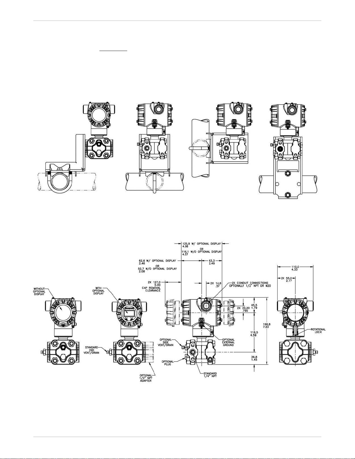
STA700 Smart Pressure Transmitter 13
Mounting & Dimensional Drawings
Reference Dimensions:
millimeters
inches
Mounting Configurations (Dual head design)
Dimensions (Dual head design)
Figure 4 - – Typical mounting dimensions of STA725 & STA745 for reference
Page 14
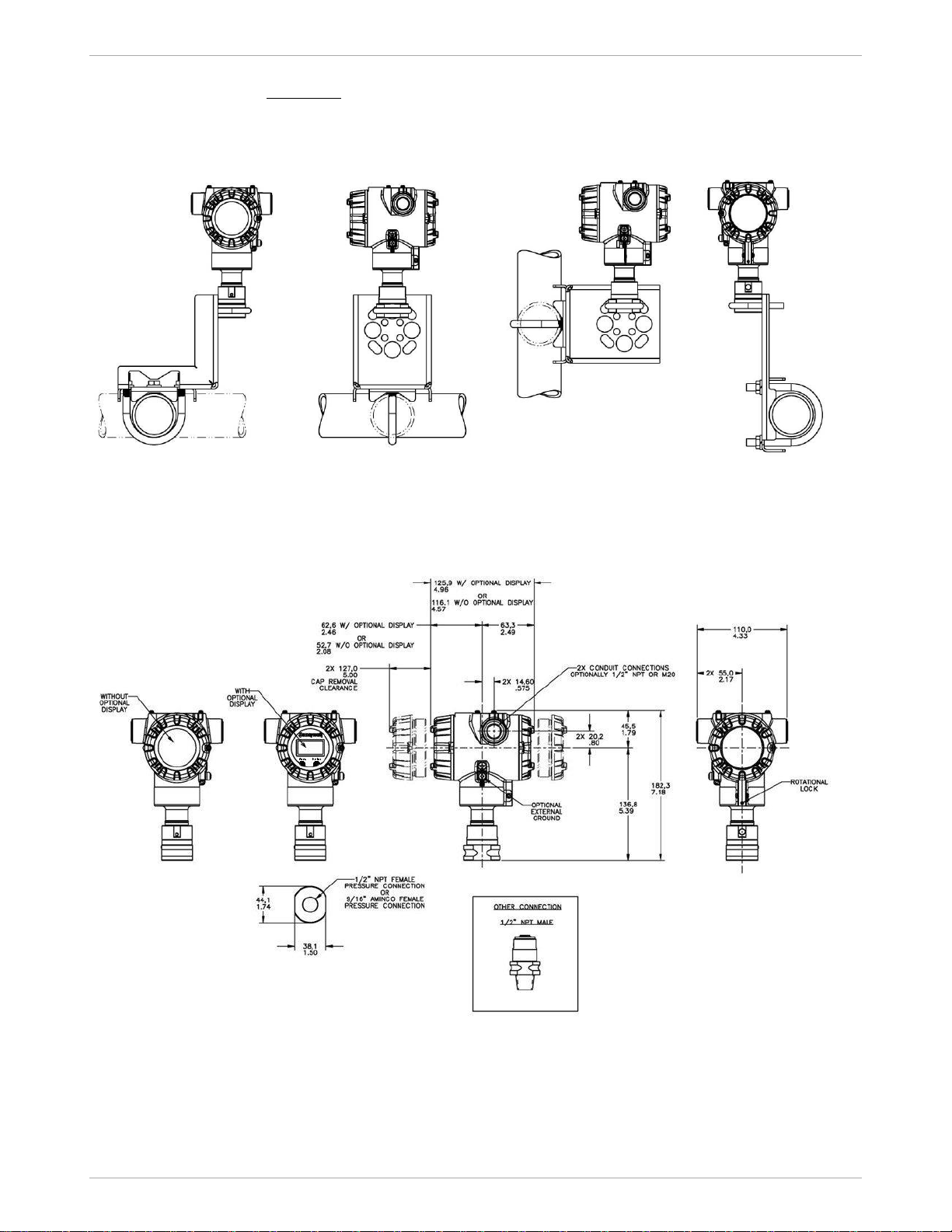
14 STA700 Smart Pressure Transmitter
Reference Dimensions:
millimeters
inches
Mounting Configurations (Inline Designs)
Dimension (Inline Design)
Figure 5 – Typical mounting dimensions of STA72S, STA74S, & STA77S for reference
Page 15
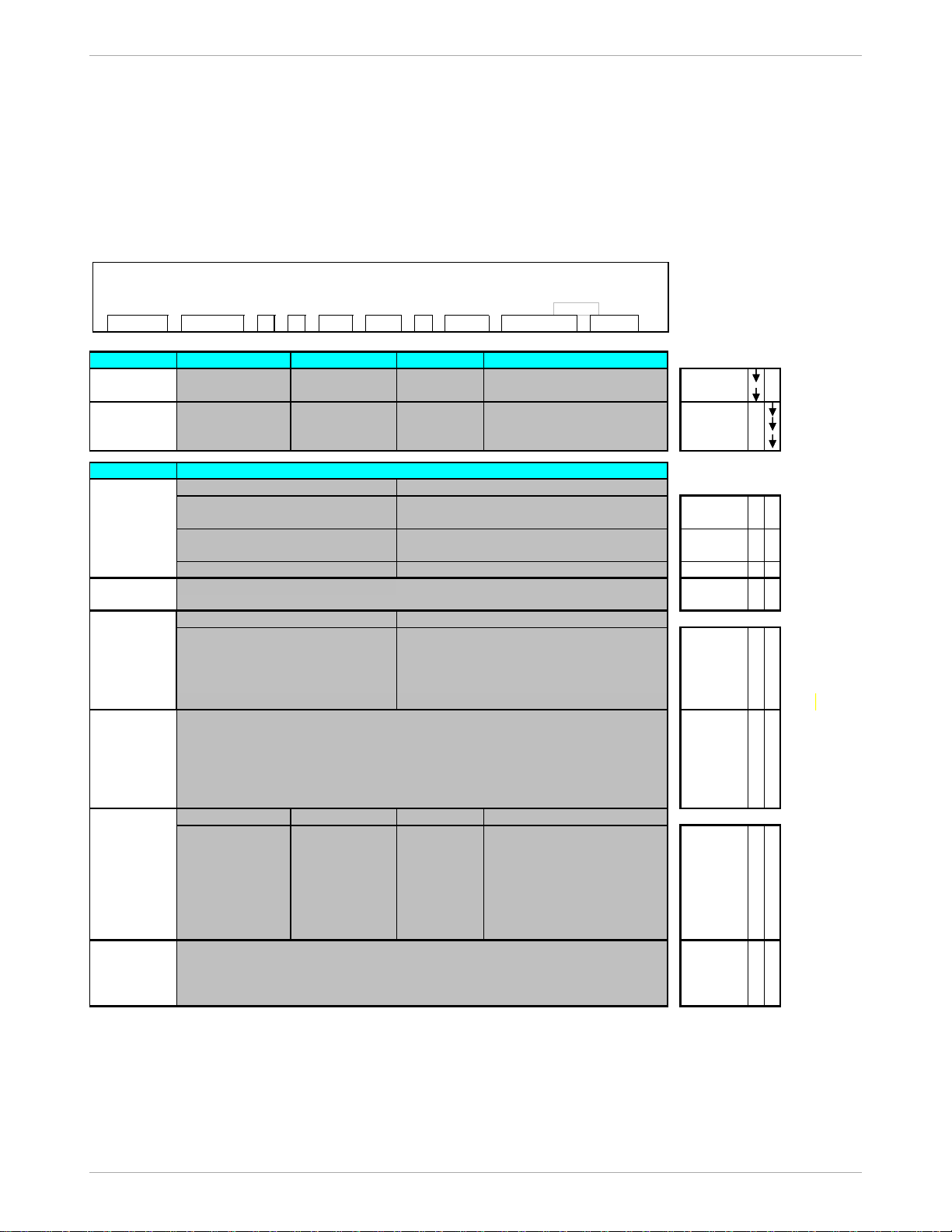
STA700 Smart Pressure Transmitter 15
Model Selection Guide
Model Selection Guides are subject to change and are inserted into the specifications as guidance only.
Model STA700
Absolute Pressure Transmitters
Model Selection Guide
34-ST-16-120 Issue 9
KEY NUMBER
URL/Max Span LRL Min Span Units Selection Availability
780 (1040) 0 (0) 50 (65.0) mm HgA (mbarA)
STA725
500 (35) 0 (0) 5 (.35) psia (barA)
STA745
780 (1040) 0 (0) 50 (65.0) mm HgA (mbarA) STA72S
500 (35) 0 (0) 5 (.35) psia (barA)
STA74S
3000 (210) 0 (0) 30 (2.1) psia (barA) STA77S
TABLE I
316L SS A _ _ _ _ _
*
Hastelloy® C - 276 B _ _ _ _ _
*
316L SS E _ _ _ _ _ * *
Hastelloy C - 276 F _ _ _ _ _ * *
Hastelloy C - 276
J _ _ _ _ _ * *
Silicone Oil 200 _ 1_ _ _ _ * *
Fluorinated Oil CTFE _ 2 _ _ _ _ * *
Same as Process Head
_ _ A _ _ _ *
Same as Process Head
1a
_ _ G _ _ _ * *
Same as Process Head
_ _ H _ _ _ *
Same as Process Head
_ _ B _ _ _ *
M20 (male) Same as Process Head _ _ N _ _ _ *
None
_ _ _ 0 _ _ *
Carbon Steel _ _ _ C _ _ *
316 SS _ _ _ S _ _ *
Grade 660 (NACE A286) with NACE 304 SS Nuts _ _ _ N _ _ *
Grade 660 (NACE A286) Bolts & Nuts _ _ _ K _ _ p
Super Duplex _ _ _ D _ _ p
Head Type Vent Type Vent Location Vent Material
None None None None _ _ _ _ 0 _ *
Single Ended
None
None None _ _ _ _ 1 _ *
Single Ended
Std Vent
Side
Matches Head Material
1
_ _ _ _ 2 _ *
Single Ended
Center Vent
Side Stainless Steel Only _ _ _ _ 3 _ t
Dual Ended
Std Vent
End
Matches Head Material
1
_ _ _ _ 4 _ *
Dual Ended
Center Vent
End Stainless Steel Only _ _ _ _ 5 _ t
Dual Ended Std Vent/ Plug Side/End
Matches Head Material
1
_ _ _ _ 6 _ *
None
_ _ _ _ _ 0
*
Teflon® or PTFE (Glass Filled)
_ _ _ _ _ A *
Viton
®
_ _ _ _ _ B *
Graphite _ _ _ _ _ C *
1
Except Carbon Steel Heads shall use 316SS Vent/Drain & Plugs
1a
STA725,745 supplied via 1/2" flange adapter same material as process head except carbon steel shall use 316 SS
1b
Reference head available only with Dual head models. In-line models supplied with process head only
Absolute
Dual Head
Absolute
In-Line
METER BODY SELECTIONS
a. Process
Head &
Diaphragm
Materials
Process Head/Reference Head Mat'l
1b
Barrier Diaphragm Material
Plated Carbon Steel /Plated Carbon Steel
316 Stainless Steel /316 Stainless Steel
Hastelloy C - 276 /316 Stainless Steel
f. Gasket
Materials
b. Fill Fluid
Size/Type
Material
9/16" Aminco
1/2" NPT (female)
1/2" NPT (male)
d. Bolt/Nuts
Materials
e. Vent/Drain
Type/Location
c. Process
Connection
G 1/2 B Threaded Fitting
Instructions: Make selections from all Tables using column below the proper arrow. Asterisk indicates availability. Letter (a) refers
to restrictions highlighted in the restrictions table. Tables delimited with dashes.
Key I II III IV V VI VII VIII IX
STA7_ _ - _ _ _ _ _ _ - _ - _ - _ _ _ - _ _ _ - _ - _ _ _ _ - _ _, _ _, _ _ - 0 0 0 0
Page 16
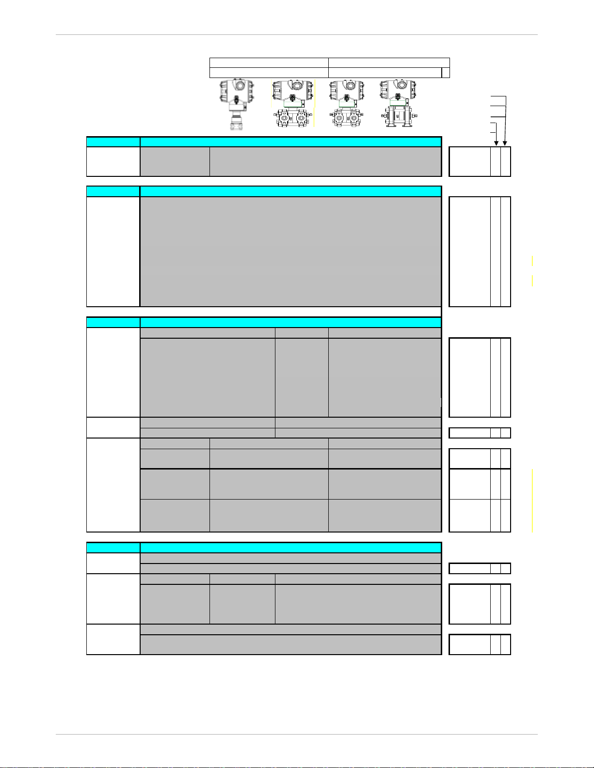
16 STA700 Smart Pressure Transmitter
REVERSED 90°/STANDARD
SELECTION 2 SELECTION 3
STA72S
STA74S
STA77S
STA725
H H H STA745
TABLE II
Meter Body & Connection Orientation
Standard
High Side Left, Ref Side Right2 / Std Head Orientation
1
* *
Reversed
Ref Side Left, High Side Right
2
2
*
90/Standard
High Side Left, Ref Side Right2 / 900 Head Rotation
3 h
TABLE III
0 * *
A
* *
B * *
C
* *
D
* *
E
* *
F
* *
G
* *
I
* *
J
* *
K * *
TABLE IV
Connection Lightning Protection
1/2 NPT None
A _ _ * *
M20 None
B _ _ * *
1/2 NPT Yes
C _ _ * *
M20 Yes
D _ _ * *
1/2 NPT None
E _ _ * *
M20 None
F _ _ * *
1/2 NPT Yes
G _ _ * *
M20 Yes H _ _ * *
_ H _ *
*
Indicator Languages
None None
_ _ 0
*
*
None None _ _ A *
*
Standard(w/Internal
Zero,Span&Config
Buttons)
EN, RU _ _ S *
*
Standard(w/Internal
Zero,Span&Config
Buttons)
EN, RU _ _ T *
*
TABLE V
1 _ _ *
*
Write Protect Fail Mode
Disabled High> 21.0mAdc Honeywell Std (3.8 - 20.8 mAdc)
_ 1 _
*
*
Disabled Low< 3.6mAdc Honeywell Std (3.8 - 20.8 mAdc)
_ 2 _
*
*
Enabled High> 21.0mAdc Honeywell Std (3.8 - 20.8 mAdc) _ 3 _ *
*
Enabled Low< 3.6mAdc Honeywell Std (3.8 - 20.8 mAdc) _ 4 _ *
*
Factory Standard
_ _ S *
*
Customer Configuration (Unit Data Required) _ _ C *
*
2
Left side/Right side as viewed from the customer connection perspective
3
NAMUR Output Limits 3.8 - 20.5mAdc can be configured by the custom
4
Process Connections will vary on In -Line models
STANDARD
SELECTION 1
4
SAEx Explosion proof, Intrinsically Safe & Non-incendive
INMETRO Explosion proof, Intrinsically Safe & Non-incendive
NEPSI Explosion proof, Intrinsically Safe & Non-incendive
EAC-Customs Union(Russia,Belarus and Kazakhstan)EX Approval Flameproof,Intrinsically Safe
TRANSMITTER ELECTRONICS SELECTIONS
Head/Connect
Orientation
AGENCY APPROVALS
No Approvals Required
<FM> Explosion proof, Intrinsically Safe, Non-incendive, & Dustproof
CSA Explosion proof, Intrinsically Safe, Non-incendive, & Dustproof
ATEX Explosion proof, Intrinsically Safe & Non-incendive
IECEx Explosion proof, Intrinsically Safe & Non-incendive
Ext Zero,Span & Config Buttons
b. Output/
Protocol
Analog Output
Digital Protocol
4-20mA dc
HART Protocol
Approvals
CCoE Explosion proof, Intrinsically Safe & Non-incendive
UATR Flameproof, Intrinsically Safe & Dustproof
a. Electronic
Housing
Material &
Connection
Type
Material
Polyester Powder Coated Aluminum
Polyester Powder Coated Aluminum
Polyester Powder Coated Aluminum
Polyester Powder Coated Aluminum
316 Stainless Steel (Grade CF8M)
316 Stainless Steel (Grade CF8M)
316 Stainless Steel (Grade CF8M)
316 Stainless Steel (Grade CF8M)
Yes
CONFIGURATION SELECTIONS
a. App S/W
Diagnostics
Standard Diagnostics
b. Output Limit,
Failsafe & Write
Protect
Settings
High & Low Output Limits
3
c. Customer
Interface
Selections
None
Yes (Zero/Span Only)
None
c. General
Configuration
General Configuration
Page 17
STA700 Smart Pressure Transmitter 17
STA72S
STA74S
STA77S
STA725
TABLE VI
STA745
Accuracy Calibration Qty
Standard Factory Std Single Calibration A * *
Standard Custom (Unit Data Required) Single Calibration B * *
TABLE VII
None None
0 _ _ _
* *
Angle Bracket Carbon Steel
1 _ _ _
* *
Angle Bracket
304 SS
2 _ _ _
* *
Angle Bracket
316 SS
3 _ _ _
* *
Marine Approved Bracket
304 SS
4_ _ _
*
Flat Bracket Carbon Steel
5 _ _ _
* *
6 _ _ _
* *
Flat Bracket 316 SS 7 _ _ _ * *
No customer tag _ 0 _ _ * *
One Wired Stainless Steel Tag (Up to 4 lines 26char/line) _ 1 _ _ * *
No Conduit Plugs or Adapters Required _ _ A0 * *
_ _ A2 n n
_ _ A6 n n
_ _ A7 m m
TABLE VIII
None - No additional options 00 * *
NACE MR0175; MR0103; ISO15156 Process wetted parts only FG * *
NACE MR0175; MR0103; ISO15156 Process wetted and non-wetted parts F7 c c
Marine (DNV,ABS,BV,KR,LR) MT d d
EN10204 Type 3.1 Material Traceability FX * *
Certificate of Conformance F3 * *
Calibration Test Report & Certificate of Conformance F1 * *
Certificate of Origin F5 * *
FMEDA(SIL 2/3) Certification FE j j
Over-Pressure Leak Test Certificate (1.5X MAWP) TP * *
Cert Clean for O2 or CL2 service per ASTM G93 OX e e
PM Certification⁵ PM * *
Extended Warranty Additional 1 year 01 * *
Extended Warranty Additional 2 years 02 * *
Extended Warranty Additional 3 years 03 * *
Extended Warranty Additional 4 years 04 * *
TABLE IX
Factory Factory Identification 0 0 0 0 * *
RESTRICTIONS
Table Selection(s) Table
c
Id _ _ _ 0,N,K,D _ _
d
Iva C, D, G, H _ _ VIIa
e
Ib _ 2 _ _ _ _
Ie
VIIa
jVbm
IVa B,D,F,H _ _
n
IVa A,C,E,G _ _
p
III
t1as
Ia A,E _ _ _ _ _
b
FIELD INSTALLABLE ACCESSORY KITS
Terminal Strip w/o Lightning Protection Kit for HART Module
Terminal Strip w/Lightning Protection for HART Module
HART Electronics Module
HART Electronics Module w/connection for external Zero/Span buttons
Standard Display Module
PRODUCT MANUALS
ACCESSORY SELECTIONS
a. Mounting
Bracket
Bracket Type
Material
Flat Bracket
304 SS
CALIBRATION & ACCURACY SELECTIONS
Calibrated Range
a. Accuracy
and
Calibration
OTHER Certif ications & Options: (String in se quence comm a delimited ( XX, XX, XX,….)
Certifications
& Warranty
b
b
b
Manufacturing Specials
b. Customer
Tag
Customer Tag Type
c.
Unassembled
Conduit
Plugs &
Adapters
Unassembled Conduit Plugs & Adapters
1/2 NPT Male to 3/4 NPT Female 316 SS Certified Conduit Adapter
1/2 NPT 316 SS Certified Conduit Plug
M20 316 SS Certified Conduit Plug
h
_ _ _ _ 4,5,6 _
1, 2, 3, 4, 5, 6, 7 _ _ _
1, 2, 3, 5, 6, 7 _ _ _
Restriction
Letter
Available Only with
Not Available with
Selection(s)
5
The PM option is available on all Smartline Pressure Transmitter process wetted parts such as process heads, flanges, bushings and vent
plugs except plated carbon steel process heads and flanges. PM option information is also available on diaphragms except STG and STA inline construction pressure transmitters.
Description
Kit Number
50129832-501
50129832-502
50129828-501
_ 1,2 _
B - No CRN number available
J _ _ _ _ _
Select Only one option from this group
ST 700 Smart Transmitter Safety Manual - English
34-ST-25-37
50129828-502
50126003-501
Description
Part Number
ST 700 Smart Transmitter User Manual - English
34-ST-25-44
ST 700 Smart Transmitter HART Communications Manual - English
34-ST-25-47
Page 18

For more information
To learn more about SmartLine Pressure
Transmitters visit www.honeywellprocess.com
Or contact your Honeywell Account Manager
Process Solutions
Honeywell
1250 W Sam Houston Pkwy S
Houston, TX 77042
Honeywell Control Systems Ltd
Honeywell House, Skimped Hill Lane
Bracknell, England, RG12 1EB
34-ST-03-120
Jan 2021
2021 Honeywell International Inc.
Shanghai City Centre, 100 Jungi Road
Shanghai, China 20061
www.honeywellprocess.com
Sales and Service
For application assistance, current specifications, ordering, pricing, and name of the nearest Authorized Distributor,
contact one of the offices below.
ASIA PACIFIC
Honeywell Process Solutions,
Phone: + 800 12026455 or
+44 (0) 1202645583
(TAC) hfs-tac-
Australia
Honeywell Limited
Phone: +(61) 7-3846 1255
FAX: +(61) 7-3840 6481
Toll Free 1300-36-39-36
Toll Free Fax:
1300-36-04-70
China – PRC - Shanghai
Honeywell China Inc.
Phone: (86-21) 5257-4568
Fax: (86-21) 6237-2826
Singapore
Honeywell Pte Ltd.
Phone: +(65) 6580 3278
Fax: +(65) 6445-3033
South Korea
Honeywell Korea Co Ltd
Phone: +(822) 799 6114
Fax: +(822) 792 9015
EMEA
Honeywell Process Solutions,
Phone: + 800 12026455 or
+44 (0) 1202645583
Email: (Sales)
or
(TAC)
Web
Knowledge Base search
engine http://bit.ly/2N5Vldi
AMERICAS
Honeywell Process Solutions,
Phone: (TAC) (800) 423-9883
or (215) 641-3610
(Sales) 1-800-343-0228
Email: (Sales)
or
(TAC)
Web
Knowledge Base search
engine http://bit.ly/2N5Vldi
Specifications are subject to change without notice.
 Loading...