

Honeywell Series A, Experion PKS A User Manual

Honeywell Process Solutions
Experion PKS
Series A Fieldbus Interface
Module
User's Guide
EP-DCX166
R400
July 2010
Release R400
Honeywell

Notices and Trademarks
Copyright 2010 by Honeywell International Sárl.
Release R400 July 2010
While this information is presented in good faith and believed to be accurate, Honeywell disclaims
the implied warranties of merchantability and fitness for a particular purpose and makes no
express warranties except as may be stated in its written agreement with and for its customers.
In no event is Honeywell liable to anyone for any indirect, special or consequential damages. The
information and specifications in this document are subject to change without notice.
Honeywell, PlantScape, Experion PKS, and TotalPlant are registered trademarks of Honeywell
International Inc.
Other brand or product names are trademarks of their respective owners.
Honeywell Process Solutions
1860 W. Rose Garden Lane
Phoenix, AZ 85027 USA
1-800 822-7673
ii Experion PKS Series A Fieldbus Interface Module User's Guide R400
Honeywell July 2010

About This Document
Provides guidelines and procedures for interf aci ng fi el d bu s devi ces with an Experion system. It
includes module installation, configuration, operation, maintenance, and FOUNDATION
Fieldbus reference data.
Release Information
Document Name Document ID
Release
Number
Publication
Date
Series A Fieldbus Interface Module User's
Guide - figd
Document Category
Purpose
EP-DCX166 R400 July 2010
R400 Experion PKS Series A Fieldbus Interface Module User's Guide iii
July 2010 Honeywell

Support and Other Contacts
Support and Other Contacts
United States and Canada
Europe, Middle East, and Africa (EMEA)
Contact:
Phone:
Fascimile:
Mail:
Contact:
Phone:
Fascimile:
Mail:
Honeywell Solution Support Center
1-800-822-7673
Calls are answered by dispatcher between 6:00 am and 4:00 pm
Mountain Standard Time. Emergency calls outside normal working hours
are received by an answering service and returned within one hour.
1-973-455-5000
Honeywell TAC, MS L17
1860 W. Garden Lane
Phoenix, AZ, 85027 USA
Honeywell TAC-EMEA
+32-2-728-2345
+32-2-728-2696
TAC-BE02
Hermes Plaza
Hermeslaan, 1H
B-1831 Diegem, Belgium
Pacific
Contact:
Phone:
Fascimile:
Mail:
Email:
Honeywell Global TAC – Pacific
1300-364-822 (toll free within Australia)
+61-8-9362-9559 (outside Australia)
+61-8-9362-9564
Honeywell Limited Australia
5 Kitchener Way
Burswood 6100, Western Australia
GTAC@honeywell.com
India
iv Experion PKS Series A Fieldbus Interface Module User's Guide R400
Honeywell July 2010
Contact:
Phone:
Fascimile:
Mail:
Email:
Honeywell Global TAC – India
+91-20- 6603-9400
+91-20- 6603-9800
Honeywell Automation India Ltd
56 and 57, Hadapsar Industrial Estate
Hadapsar, Pune –411 013, India
Global-TAC-India@honeywell.com

Korea
Contact:
Phone:
Fascimile:
Mail:
Email:
Honeywell Global TAC – Korea
+82-2-799-6317
+82-2-792-9015
Honeywell Co., Ltd
4F, Sangam IT Tower
1590, DMC Sangam-dong, Mapo-gu
Seoul, 121-836, Korea
Global-TAC-Korea@honeywell.com
People’s Republic of China
Contact:
Phone:
Mail:
Email:
Honeywell Global TAC – China
+86- 21-2219-6888
800-820-0237
400-820-0386
Honeywell (China) Co., Ltd
33/F, Tower A, City Center, 100 Zunyi Rd.
Shanghai 200051, People’s Republic of China
Global-TAC-China@honeywell.com
Singapore
Contact:
Phone:
Fascimile:
Mail:
Email:
Honeywell Global TAC – South East Asia
+65-6580-3500
+65-6580-3501
+65-6445-3033
Honeywell Private Limited
Honeywell Building
17, Changi Business Park Central 1
Singapore 486073
GTAC-SEA@honeywell.com
Support and Other Contacts
Taiwan
R400 Experion PKS Series A Fieldbus Interface Module User's Guide v
July 2010 Honeywell
Contact:
Phone:
Fascimile:
Mail:
Email:
Honeywell Global TAC – Taiwan
+886-7-536-2567
+886-7-536-2039
Honeywell Taiwan Ltd.
17F-1, No. 260, Jhongshan 2nd Road.
Cianjhen District
Kaohsiung, Taiwan, ROC
Global-TAC-Taiwan@honeywell.com

Support and Other Contacts
Japan
Contact:
Phone:
Fascimile:
Mail:
Email:
Honeywell Global TAC – Japan
+81-3-6730-7160
+81-3-6730-7228
Honeywell Japan Inc.
New Pier Takeshiba, South Tower Building,
20th Floor, 1-16-1 Kaigan, Minato-ku,
Tokyo 105-0022, Japan
Global-TAC-JapanJA25@honeywell.com
Elsewhere
Call your nearest Honeywell office.
World Wide Web
Honeywell Solution Support Online:
http://www.honeywell.com/ps
Training Classes
Honeywell Automation College:
http://www.automationcollege.com
vi Experion PKS Series A Fieldbus Interface Module User's Guide R400
Honeywell July 2010
Symbol Definitions
Symbol Definitions
The following table lists those symbols used in this document to denote certain conditio ns.
Symbol Definition
CAUTION
ATTENTION: Identifies information that requires special
consideration.
TIP: Identifies advice or hints for the user, often in terms of
performing a task.
REFERENCE -EXTERNAL: Identifies an additional source of
information outside of the bookset.
REFERENCE - INTERNAL: Identifies an additional source of
information within the bookset.
Indicates a situation which, if not avoided, may result in equipment
or work (data) on the system being damaged or lost, or may result in
the inability to properly operate the process.
CAUTION: Indicates a potentially hazardous situation which, if not
avoided, may result in minor or moderate injury. It may also be used
to alert against unsafe practices.
CAUTION symbol on the equipment refers the user to the product
manual for additional information. The symbol appears next to
required information in the manual.
WARNING: Indicates a potentially hazardous situation, which, if not
avoided, could result in serious injury or death.
WARNING symbol on the equipment refers the user to the product
manual for additional information. The symbol appears next to
required information in the manual.
R400 Experion PKS Series A Fieldbus Interface Module User's Guide vii
July 2010 Honeywell
Symbol Definitions
Symbol Definition
WARNING, Risk of electrical shock: Potential shock hazard where
HAZARDOUS LIVE voltages greater than 30 Vrms, 42.4 Vpeak, or
60 VDC may be accessible.
ESD HAZARD: Danger of an electro-static discharge to which
equipment may be sensitive. Observe precautions for handling
electrostatic sensitive devices.
Protective Earth (PE) terminal: Provided for connection of the
protective earth (green or green/yellow) supply system conductor.
Functional earth terminal: Used for non-safety purposes such as
noise immunity improvement. NOTE: This connection shall be
bonded to Protective Earth at the source of supply in accordance
with national local electrical code requirements.
Earth Ground: Functional earth connection. NOTE: This
connection shall be bonded to Protective Earth at the source of
supply in accordance with national and local electrical code
requirements.
Chassis Ground: Identifies a connection to the chassis or frame of
the equipment shall be bonded to Protective Earth at the source of
supply in accordance with national and local electrical code
requirements.
viii Experion PKS Series A Fieldbus Interface Module User's Guide R400
Honeywell July 2010

Contents
1. INTRODUCTION ..........................................................................23
1.1 Where to look for information......................................................................23
Contents guide.....................................................................................................................23
1.2 Conventions...................................................................................................24
Terms and type representations...........................................................................................24
2. WHAT IS FIELDBUS?..................................................................27
2.1 Fieldbus Organization ..................................................................................27
About the Fieldbus Foundation ............................................................................................27
Want more information?.......................................................................................................27
2.2 Fieldbus Technology .................................................................................... 27
Reference.............................................................................................................................27
2.3 Fieldbus Terms..............................................................................................27
Description...........................................................................................................................27
3. FIELDBUS INTEGRATION WITH EXPERION SYSTEM.............33
3.1 Overview ........................................................................................................33
Background..........................................................................................................................33
CIOM-A FIM versus Series C FIM........................................................................................33
Non-Redundant Fieldbus integrated architecture for CIOM-A FIM.......................................34
Redundant Fieldbus integrated architecture for CIOM-A FIM ..............................................35
Fieldbus Interface Module (FIM) - the key to integration......................................................37
Redundancy Module - the key to redundant operation.........................................................37
Control Builder serves as common configuration tool ..........................................................37
Parameter Definition Editor serves as key interoperability tool ............................................39
Parameter Definition Editor supports Fieldbus Methods......................................................40
Station provides centralized operator interface....................................................................41
3.2 Control Integration........................................................................................42
FIM handles data integration................................................................................................42
About link object...................................................................................................................42
Network Management description ........................................................................................42
System Management description.........................................................................................43
About device objects............................................................................................................43
About VFD objects...............................................................................................................43
Type creation makes integration possible............................................................................44
R400 Experion PKS Series A Fieldbus Interface Module User's Guide ix
July 2010 Honeywell

Contents
Fieldbus device Analog Input integration............................................................................. 44
Fieldbus Analog Input data manipulation ............................................................................ 45
Fieldbus device Analog Output or PID integration............................................................... 46
Fieldbus Analog Output or PID data manipulation............................................................... 48
Fieldbus device Discrete Input integration........................................................................... 50
Fieldbus Discrete Input data manipulation .......................................................................... 51
Fieldbus device Discrete Output data integration................................................................ 52
Fieldbus Discrete Output data manipulation........................................................................ 53
Interface Connections Summary......................................................................................... 54
A word about SCM parameter interaction ........................................................................... 54
Fieldbus status data details................................................................................................. 55
Fieldbus status indications .................................................................................................. 57
3.3 Control Mode Interaction..............................................................................57
Fieldbus block modes versus control modes....................................................................... 57
Control mode priorities and indications ............................................................................... 59
Rotary Switch Model versus Toggle Switch Model.............................................................. 61
Display indications and mode calculation............................................................................ 62
Access control through GRANT_DENY parameter............................................................. 63
3.4 Link and Block Schedules............................................................................64
Link Active Scheduler (LAS) and Link Master ..................................................................... 64
Link Schedule...................................................................................................................... 66
Function block execution schedule...................................................................................... 67
3.5 Tags, Addresses, and Live List....................................................................69
Tag and address assignments ............................................................................................ 69
A word about fieldbus address assignments in Control Builder........................................... 70
Live List and Uncommissioned Devices.............................................................................. 70
3.6 Notification Scheme......................................................................................71
Fieldbus versus Experion Alarm Priorities........................................................................... 71
Advanced Alarming............................................................................................................. 73
Fieldbus Alarm Conditions .................................................................................................. 73
Loading alarm conditions .................................................................................................... 77
Alarm server operation........................................................................................................ 77
3.7 CIOM-A FIM Redundancy Functionality......................................................78
About CIOM-A FIM redundancy.......................................................................................... 78
CIOM-A FIM versus C200 CPM redundancy....................................................................... 79
Switchover and Secondary readiness................................................................................. 80
Switchover behavior considerations.................................................................................... 81
Failure conditions and switchover ....................................................................................... 82
Fieldbus network switchover considerations....................................................................... 83
Switchover versus fieldbus network activities...................................................................... 84
Switchover events............................................................................................................... 86
3.8 Block Instantiation Support..........................................................................86
About instantiable blocks..................................................................................................... 86
Control Builder supports block instantiation ........................................................................ 86
x Experion PKS Series A Fieldbus Interface Module User's Guide R400
Honeywell July 2010

Contents
Instantiable block implementation considerations ................................................................87
4. INSTALLATION ...........................................................................99
4.1 Planning Considerations..............................................................................99
Experion system references.................................................................................................99
Installation declaration .........................................................................................................99
CIOM-A FIM and I/O module allowance...............................................................................99
CIOM-A FIM only chassis configuration considerations.....................................................100
Fieldbus component references.........................................................................................101
Fieldbus network references..............................................................................................102
Fieldbus wiring selection and calculation...........................................................................103
Intrinsically safe applications..............................................................................................104
4.2 Installing CIOM-A Fieldbus Interface Module TC-FFIF01........................104
Front View..........................................................................................................................104
Inserting module in chassis................................................................................................105
Connecting RTP cable to module.......................................................................................107
Loading FIM firmware ........................................................................................................108
4.3 Installing Fieldbus RTP TC-FFRU01/TC-FFRP02 or RRTP TC-FFSU01/TC-
FFSP02....................................................................................................................109
Front view...........................................................................................................................109
Mounting on a DIN rail .......................................................................................................110
Mounting Dimensions.........................................................................................................111
Wiring.................................................................................................................................112
5. CONFIGURATION .....................................................................117
5.1 Before You Start..........................................................................................117
What do you know about Control Builder?.........................................................................117
Do you know how to configure a Control Processor Module?............................................117
Can you configure a Control Module?................................................................................117
Are you familiar with your system architecture?.................................................................117
Do you understand and have experience with fieldbus?....................................................117
Are you Ready? .................................................................................................................118
5.2 Non-Experion Interface Precautions.........................................................118
5.3 Free VCR Recommendation....................................................................... 119
5.4 Configuring Fieldbus Components In a Control Strategy ...................... 120
About control strategy configuration...................................................................................120
Example Application and Control Strategy for Procedural Reference................................120
Configuration considerations only for redundant CIOM-A FIM applications.......................122
Adding CIOM-A FIM block to Project .................................................................................123
Checking link configuration ................................................................................................133
Creating a Fieldbus device type from vendor DD...............................................................141
R400 Experion PKS Series A Fieldbus Interface Module User's Guide xi
July 2010 Honeywell

Contents
Editing device block parameters........................................................................................ 145
Adding a fieldbus device to Project ................................................................................... 146
Assigning a device to a Link in Project.............................................................................. 151
Checking device configuration........................................................................................... 154
Making fieldbus block template and assigning function block to device............................ 164
Creating Control Module for sample PID loop - Optional................................................... 172
5.5 Loading Components Online......................................................................202
About load operations ....................................................................................................... 202
About Load Dialog box...................................................................................................... 204
Load order guidelines........................................................................................................ 205
General load considerations.............................................................................................. 206
Fieldbus device states....................................................................................................... 206
Fieldbus device matching rules......................................................................................... 207
Loading a CIOM-A FIM and its Links................................................................................. 208
Matching uncommissioned device to project device or vice versa .................................... 211
Loading Link contents or fieldbus device........................................................................... 219
5.6 Configuring Advanced Alarming ...............................................................225
Overview........................................................................................................................... 225
Opening the Configuration dialog box............................................................................... 226
Configuring/creating a condition........................................................................................ 227
Managing the conditions ................................................................................................... 230
Enabling or disabling a condition ....................................................................................... 230
Assigning criticalities and priorities.................................................................................... 232
Editing an existing condition.............................................................................................. 233
5.7 Block Offnet Diagnostic Alarm...................................................................234
Behavior of the Block Offnet and Device Offnet System alarms in various communication loss
scenarios........................................................................................................................... 235
Behavior of the Block Offnet and Device Offnet System alarms in various operational
scenarios........................................................................................................................... 236
5.8 Configuring non-cache parameters...........................................................238
5.9 Summary ......................................................................................................240
6. OPERATION..............................................................................243
6.1 Monitoring Fieldbus Functions Through Station Displays.....................243
Using Station Detail displays............................................................................................. 243
6.2 Foundation Fieldbus Detail Displays/Faceplates.....................................244
Detail Displays contents based on FF control points loading............................................ 245
Naming conventions for Detail Displays............................................................................ 245
Tabs of FF Detail Displays................................................................................................ 246
Detail Displays tabs of the different Foundation Fieldbus blocks....................................... 247
Common functionalities of faceplates................................................................................ 250
FF Detail Displays example templates for Control Builder ................................................ 252
xii Experion PKS Series A Fieldbus Interface Module User's Guide R400
Honeywell July 2010

Contents
Using Station Event Summary display...............................................................................252
6.3 Monitoring Fieldbus Functions Through Monitoring Tab.......................253
Inactivating/Activating a Link..............................................................................................253
Monitoring/Interacting with given component/block............................................................256
Checking/changing fieldbus device functional class...........................................................257
Checking live list and interacting with uncommissioned devices........................................264
Viewing and optimizing Link schedule configuration..........................................................267
CheckingCIOM-A FIM redundancy status and initiating manual switchover ......................273
Using Controller menu functions........................................................................................275
7. FIELDBUS DEVICE COMMISSIONING.....................................277
7.1 Getting Started ............................................................................................277
Read this first.....................................................................................................................277
Initial checks and operations..............................................................................................279
7.2 Connecting Devices....................................................................................280
7.3 Checking Device..........................................................................................282
7.4 Checking Control Strategy.........................................................................283
7.5 Flowchart Summary....................................................................................284
8. MAINTENANCE, CHECKOUT, AND CALIBRATION................287
8.1 Adding, Removing and Replacing Components......................................287
About removal and insertion under power (RIUP)..............................................................287
General procedure .............................................................................................................287
Guidelines for adding fieldbus device to "live"/operating Link ............................................288
Using optional safe handling of new devices......................................................................289
Replacing a failed device with a like device having the same model name and device revision
...........................................................................................................................................290
Replacing a failed device with a different device using a different block type ....................297
8.2 Unlike Device Replacement Report...........................................................317
8.3 Replacing Device Template with a Different One ....................................320
Prerequisites......................................................................................................................320
Considerations...................................................................................................................321
Using Unlike Template Replacement wizard to make device replacements......................321
8.4 Correcting Some Common UTR errors.....................................................328
8.5 Upgrading Firmware in Uncommissioned Device...................................328
8.6 Changing or Clearing Tag and/or Address of Uncommissioned Device332
8.7 Using Fieldbus Device Simulate Function ...............................................334
R400 Experion PKS Series A Fieldbus Interface Module User's Guide xiii
July 2010 Honeywell

Contents
8.8 Preparing Fieldbus Device for a Move or Software Migration................343
Migrating Fieldbus device type to a release supporting Enable Block Offnet Diagnostic Alarm
.......................................................................................................................................... 347
8.9 Interpreting Component LED Indications .................................................348
CIOM-A FIM LED indications ............................................................................................ 348
8.10 FIM Self-Test Diagnostic Codes .............................................................349
8.11 Checking Fieldbus Device Calibration...................................................358
8.12 Using Fieldbus Methods Manager..........................................................359
Prerequisites ..................................................................................................................... 359
Launching Methods Manager............................................................................................ 360
Interacting with Methods Manager .................................................................................... 360
9. EXPERION PKS HOST REGISTRATION ................................. 365
9.1 Overview.......................................................................................................365
New features..................................................................................................................... 365
Conditional support for FF devices.................................................................................... 367
EDDL................................................................................................................................. 368
DD View tab ...................................................................................................................... 368
Following are some of the considerations for FF blocks with DD View. ............................ 373
Persistent data handling.................................................................................................... 375
10. APPENDIX A.............................................................................377
10.1 Fieldbus Technology ...............................................................................377
Open communications architecture................................................................................... 377
Communication layer description ...................................................................................... 378
10.2 Standard Function Blocks.......................................................................381
Overview........................................................................................................................... 383
About modes of operation................................................................................................. 384
Analog Input block............................................................................................................. 386
Analog Output block.......................................................................................................... 388
Bias/Gain block ................................................................................................................. 390
Control Selector block ....................................................................................................... 393
Discrete Input block........................................................................................................... 396
Discrete Output block........................................................................................................ 397
Manual Loader block......................................................................................................... 400
Proportional/Derivative block............................................................................................. 402
Ratio block ........................................................................................................................ 412
10.3 Device Descriptions and Block Parameters..........................................416
About Device Descriptions ................................................................................................ 416
Device Description Language ........................................................................................... 416
Device Description infrastructure....................................................................................... 416
xiv Experion PKS Series A Fieldbus Interface Module User's Guide R400
Honeywell July 2010

Contents
Block parameter definitions................................................................................................417
10.4 Fieldbus Foundation Documents...........................................................418
Reference Data..................................................................................................................418
11. APPENDIX B..............................................................................419
11.1 Standard Function Block Parameters ...................................................419
ACK_OPTION....................................................................................................................419
ALARM_HYS .....................................................................................................................419
ALARM_SUM .....................................................................................................................419
ALERT_KEY ......................................................................................................................420
BAL_TIME..........................................................................................................................421
BIAS...................................................................................................................................421
BKCAL_HYS......................................................................................................................422
BKCAL_IN ..........................................................................................................................422
BKCAL_OUT......................................................................................................................423
BKCAL_OUT_D .................................................................................................................423
BKCAL_SEL_1...................................................................................................................424
BKCAL_SEL_2...................................................................................................................424
BKCAL_SEL_3...................................................................................................................425
BLOCK_ALM......................................................................................................................425
BLOCK_ERR .....................................................................................................................426
BLOCK_ERR.DISABLED...................................................................................................427
BYPASS.............................................................................................................................428
CAS_IN..............................................................................................................................428
CAS_IN_D..........................................................................................................................429
CHANNEL..........................................................................................................................429
CLR_FSTATE....................................................................................................................430
CONFIRM_TIME................................................................................................................430
CONTROL_OPTS..............................................................................................................431
CYCLE_SEL ...................................................................................................................... 432
CYCLE_TYPE....................................................................................................................432
DEV_REV ..........................................................................................................................433
DEV_TYPE ........................................................................................................................433
DD_RESOURCE................................................................................................................434
DD_REV.............................................................................................................................434
DISC_ALM.........................................................................................................................435
DISC_LIM...........................................................................................................................435
DISC_PRI...........................................................................................................................436
DV_HI_ALM.......................................................................................................................436
DV_HI_LIM.........................................................................................................................437
DV_HI_PRI.........................................................................................................................437
DV_LO_ALM......................................................................................................................438
DV_LO_LIM .......................................................................................................................439
DV_LO_PRI .......................................................................................................................439
FAULT_STATE..................................................................................................................439
FEATURES........................................................................................................................440
R400 Experion PKS Series A Fieldbus Interface Module User's Guide xv
July 2010 Honeywell

Contents
FEATURE_SEL................................................................................................................. 440
FF_GAIN........................................................................................................................... 441
FF_SCALE........................................................................................................................ 441
FF_VAL............................................................................................................................. 442
FIELD_VAL ....................................................................................................................... 442
FIELD_VAL_D................................................................................................................... 443
FREE_SPACE................................................................................................................... 444
FREE_TIME...................................................................................................................... 444
FSTATE_TIME.................................................................................................................. 445
FSTATE_VAL.................................................................................................................... 445
FSTATE_VAL_D............................................................................................................... 446
GAIN .................................................................................................................................446
GRANT_DENY.................................................................................................................. 446
HARD_TYPES ..................................................................................................................447
HI_ALM ............................................................................................................................. 447
HI_HI_ALM........................................................................................................................ 448
HI_HI_LIM......................................................................................................................... 449
HI_HI_PRI......................................................................................................................... 449
HI_LIM............................................................................................................................... 450
HI_PRI............................................................................................................................... 450
IO_OPTS........................................................................................................................... 451
IN....................................................................................................................................... 452
IN_1................................................................................................................................... 452
LIM_Notify......................................................................................................................... 453
L_TYPE............................................................................................................................. 453
LO_ALM............................................................................................................................ 454
LO_LIM ............................................................................................................................. 455
LO_LO_ALM ..................................................................................................................... 455
LO_LO_LIM....................................................................................................................... 456
LO_LO_PRI....................................................................................................................... 456
LO_PRI ............................................................................................................................. 457
LOW_CUT......................................................................................................................... 457
MANUFAC_ID................................................................................................................... 458
MAX_NOTIFY ................................................................................................................... 458
MEMORY_SIZE................................................................................................................ 459
MIN_CYCLE_T.................................................................................................................. 459
MODE_BLK....................................................................................................................... 460
NV_CYCLE_T................................................................................................................... 460
OFFNETALM_ENABLED.................................................................................................. 461
OUT................................................................................................................................... 461
OUT_D.............................................................................................................................. 462
OUT_HI_LIM..................................................................................................................... 463
OUT_LO_LIM.................................................................................................................... 463
OUT_SCALE..................................................................................................................... 463
OUT_STATE..................................................................................................................... 464
PV .....................................................................................................................................465
PV_D................................................................................................................................. 465
PV_FTIME......................................................................................................................... 466
xvi Experion PKS Series A Fieldbus Interface Module User's Guide R400
Honeywell July 2010

Contents
PV_SCALE.........................................................................................................................466
PV_STATE.........................................................................................................................467
RA_FTIME .........................................................................................................................467
RATE .................................................................................................................................468
RCAS_IN............................................................................................................................468
RCAS_IN_D.......................................................................................................................469
RCAS_OUT........................................................................................................................469
RCAS_OUT_D...................................................................................................................470
READBACK .......................................................................................................................471
READBACK_D...................................................................................................................471
RESET...............................................................................................................................472
RESTART ..........................................................................................................................472
ROUT_IN ...........................................................................................................................473
ROUT_OUT .......................................................................................................................474
RS_STATE.........................................................................................................................474
SEL_1 ................................................................................................................................475
SEL_2 ................................................................................................................................475
SEL_3 ................................................................................................................................476
SEL_TYPE.........................................................................................................................477
SET_FSTATE ....................................................................................................................477
SHED_OPT........................................................................................................................478
SHED_RCAS.....................................................................................................................478
SHED_ROUT.....................................................................................................................479
SIMULATE.........................................................................................................................479
SIMULATE_D.....................................................................................................................480
SP......................................................................................................................................481
SP_D..................................................................................................................................482
SP_HI_LIM .........................................................................................................................482
SP_LO_LIM........................................................................................................................483
SP_RATE_DN....................................................................................................................483
SP_RATE-UP.....................................................................................................................484
ST_REV.............................................................................................................................484
STATUS_OPTS.................................................................................................................484
STRATEGY........................................................................................................................486
TAG_DESC........................................................................................................................486
TEST_RW..........................................................................................................................487
TRK_IN_D..........................................................................................................................488
TRK_SCALE......................................................................................................................488
TRK_VAL...........................................................................................................................489
UPDATE_EVT....................................................................................................................490
WRITE_ALM......................................................................................................................490
WRITE_LOCK....................................................................................................................491
WRITE_PRI........................................................................................................................491
XD_SCALE ........................................................................................................................492
XD_STATE.........................................................................................................................493
12. APPENDIX C..............................................................................495
R400 Experion PKS Series A Fieldbus Interface Module User's Guide xvii
July 2010 Honeywell

Contents
12.1 Fieldbus Status Display Indications ......................................................495
12.2 Substatus Definitions for Quality Status...............................................502
13. APPENDIX D.............................................................................507
13.1 Mode Change Conditions........................................................................507
14. APPENDIX E ............................................................................. 511
14.1 Fieldbus Wiring Considerations.............................................................511
Fieldbus topologies ........................................................................................................... 511
Power Conditioning........................................................................................................... 512
Power distribution.............................................................................................................. 513
Signal degradation limitations............................................................................................ 513
Cable guidelines summary................................................................................................ 514
Cable Attenuation.............................................................................................................. 515
Signal distortion versus capacitance................................................................................. 515
Attenuation calculation summary....................................................................................... 516
Cable test.......................................................................................................................... 516
15. APPENDIX F..............................................................................517
15.1 About Parameter Definition Editor for Fieldbus Device Block............517
16. APPENDIX G.............................................................................519
16.1 Loading CIOM-A FIM firmware................................................................519
Checking CIOM-A FIM firmware status............................................................................. 519
Checking firmware version................................................................................................ 520
Loading Boot code ............................................................................................................525
Loading Personality image................................................................................................ 529
17. APPENDIX H.............................................................................533
17.1 Important Functional Considerations....................................................533
General ............................................................................................................................. 533
18. APPENDIX I...............................................................................539
18.1 Link Parameters Reference.....................................................................539
Background....................................................................................................................... 539
More detailed information.................................................................................................. 540
xviii Experion PKS Series A Fieldbus Interface Module User's Guide R400
Honeywell July 2010

Contents
18.2 Description...............................................................................................540
Parameters for Link Configuration in Project Mode............................................................540
Parameters for Link Configuration in Monitor Mode...........................................................551
Some term abbreviations ...................................................................................................555
19. APPENDIX J ..............................................................................557
19.1 Load Interactions for Fieldbus Related Operations.............................557
Summary............................................................................................................................557
R400 Experion PKS Series A Fieldbus Interface Module User's Guide xi x
July 2010 Honeywell

Contents
Tables
Tables
Table 1 CIOM-AFIM LED Interpretations....................................................................348
Table 2 CONTROL_OPTS Bit Selections...................................................................431
Table 3 IO_OPTS Bit Selections.................................................................................451
Table 4 STATUS_OPTS Bit Selections ......................................................................485
xx Experion PKS Series A Fieldbus Interface Module User's Guide R400
Honeywell July 2010

Contents
Figures
Figures
Figure 1 Sample system architecture for non-redundant Fieldbus integration for CIOM-A
FIM..........................................................................................................................34
Figure 2 Sample system architecture for redundant Fieldbus integration for CIOM-A FIM.
................................................................................................................................36
Figure 3 Project tab in Control Builder has new icons for fieldbus components..........39
Figure 4 Typical Parameter Definition Editor view for selected fieldbus device block.40
Figure 5 Sample Fieldbus Methods view in Parameter Definition Editor.....................41
Figure 6 Integration of fieldbus device analog input signal with Control Builder control
strategy...................................................................................................................45
Figure 7 Integration of fieldbus device analog output signal with Control Builder control
strategy...................................................................................................................47
Figure 8 Integration of fieldbus device PID control with Control Builder control strategy48
Figure 9 Integration of fieldbus device digital input signal with Control Builder control
strategy...................................................................................................................51
Figure 10 Integration of fieldbus device digital output signal with Control Builder control
strategy...................................................................................................................53
Figure 11 Block mode calculation summary.................................................................63
Figure 12 Algorithm execution phase sequence..........................................................69
Figure 13 Summary of address allocations for fieldbus devices..................................70
Figure 14 Typical RCP setup in 10-slot chassis...........................................................79
Figure 15 Double-Wide CIOM-A Fieldbus Interface Module TC-FFIF01...................105
Figure 16 RTP model TC-FFRU01 is unpowered and can be used in Division 2
hazardous locations; model TC-FFRP02 is powered and can be used to power
fieldbus devices in Intrinsically Safe applications.................................................109
Figure 17 Redundant RTP model TC-FFSU01 is unpowered and can be used in Division
2 hazardous locations; model TC-FFSP02 is powered and can be used to power
fieldbus devices in Intrinsically Safe applications.................................................110
Figure 18 Simplified wiring schematic for RTP model TC-FFRU01, unpowered. Users
must provide conditioned 24 Vdc power for the Links - Not shown.....................114
Figure 19 Simplified wiring schematic for RRTP model TC-FFXXXX, unpowered. Users
must provide conditioned 24 Vdc power for the Links - Not shown.....................115
Figure 20 Simplified wiring schematic for RTP model TC-FFRP02, powered. Users must
provide 24 Vdc power supply for the GI/IS power supplies..................................116
Figure 21 Sample Application and Control Strategy Integrating Fieldbus Devices with an
Experion System. .................................................................................................121
Figure 22 Completed CM101 for sample loop............................................................197
Figure 23 Sample CM with Device Control block for pump control in sample loop. ..198
Figure 24 Completed CM102 with parameter connections for sample loop interlocks.201
Figure 25 Overview of load operations used to initiate components online...............203
Figure 26 Load Dialog box provides more load choices. ...........................................204
Figure 27 Typical FIM Detail display in Station. .........................................................244
R400 Experion PKS Series A Fieldbus Interface Module User's Guide xxi
July 2010 Honeywell

Contents
Figures
Figure 28 FF PID Main Tab Detail Display when loaded in CEE Environment..........249
Figure 29 FF PID Main Tab Detail Display when loaded to FFLINK. .........................250
Figure 30 Event Summary display includes fieldbus related details...........................252
Figure 31 Sample Link Schedule configuration display in Project..............................270
Figure 32 Sample Link Schedule configuration display in Monitoring. .......................271
Figure 33 FIM front panel indicators. ..........................................................................348
Figure 34 Typical Tune tab for fieldbus device's Transducer block............................358
Figure 35 Typical Other tab for fieldbus device's Transducer block...........................359
Figure 36 OSI versus Fieldbus communication model. ..............................................377
Figure 37 User Application (or Function Block Application Process) based on blocks.381
Figure 38 Using Function Blocks in fieldbus devices to form a control loop...............384
Figure 39 Functional schematic for Analog Input function block. ...............................386
Figure 40 Functional schematic for Analog Output function block..............................389
Figure 41 Functional schematic for Bias/Gain function block.....................................391
Figure 42 Functional schematic for Control Selector function block...........................394
Figure 43 Functional schematic for Discrete Input function block. .............................396
Figure 44 Functional schematic for Discrete Output function block............................398
Figure 45 Functional schematic for Manual Loader function block.............................400
Figure 46 Functional schematic for Proportional/Derivative function block................403
Figure 47 Functional schematic for Proportional/Integral/Derivative function block...408
Figure 48 Functional schematic for Ratio function block. ...........................................412
Figure 49 Device Descriptions infrastructure..............................................................417
Figure 50 Overview of fieldbus wiring topologies........................................................511
Figure 51 Communications entity architecture............................................................539
xxii Experion PKS Series A Fieldbus Interface Module User's Guide R400
Honeywell July 2010

1. Introduction
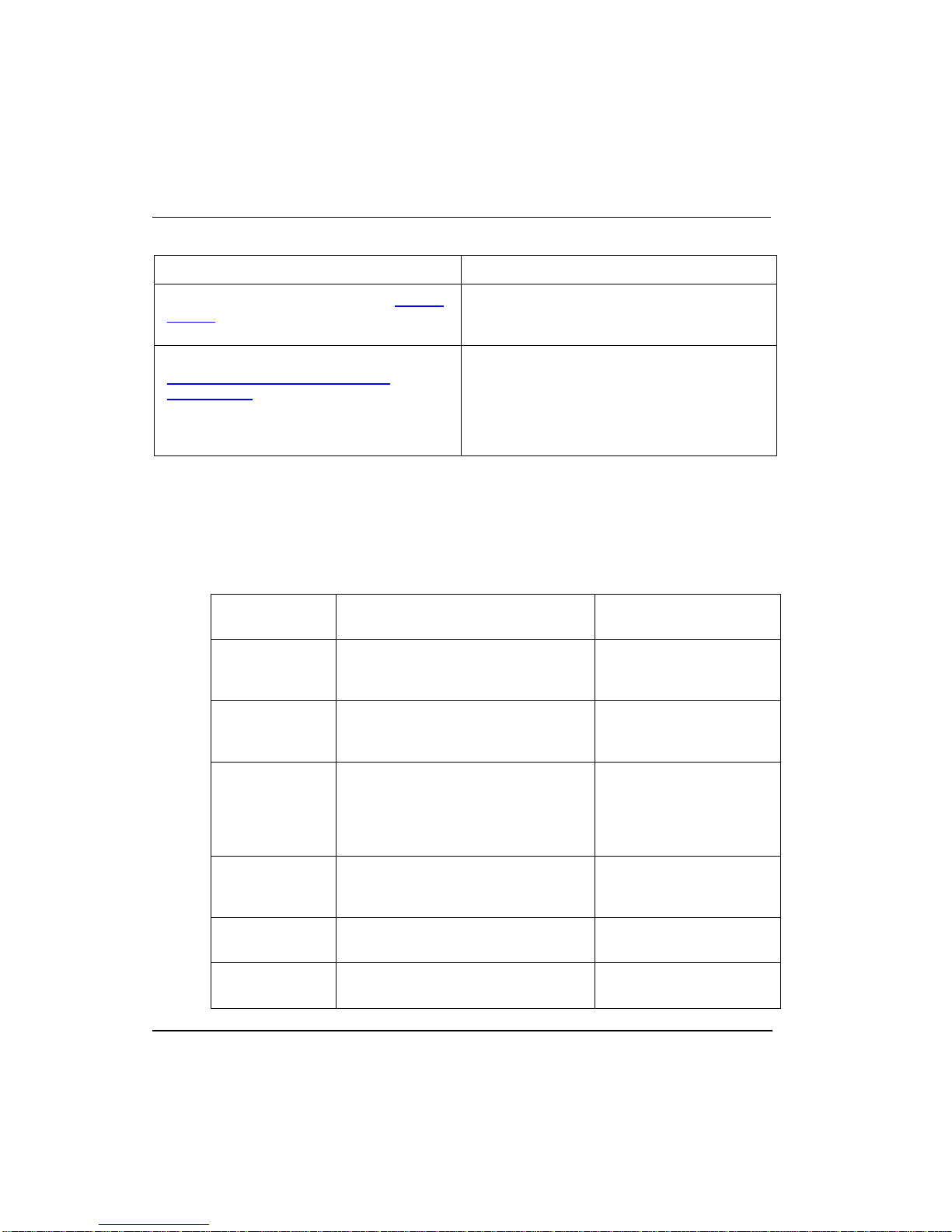
1.1 Where to look for information
Contents guide
Read this section, If you,
What is Fieldbus? - Fieldbus Organization
Have no idea what the Fieldbus Foundation
is or what constitutes the F
Fieldbus technology. This section lists some
common fieldbus terms for reference. It also
references, which includes descriptions of
some standard fieldbus function blocks and
describes the role of Device Descriptions and
block parameters for general reference.
OUNDATION
TM
TM
Fieldbus Integration With Experion
System - Control Integration
Installation - Planning Considerations
Configuration- Configuring Fieldbus
Components In a Control Strategy
Operation - Monitoring Fieldbus Functions
Through Monitoring Tab
Want some insight on what functional
relationships result from the integration of
fieldbus devices with an Experion system. The
information in this section will be helpful
background for planning and configuring your
control strategy.
Will be responsible for setting up the hardware
infrastructure to support fieldbus devices. This
section identifies the things you should
consider before installing any equipment and
provides detailed procedures for how to install
the Fieldbus Interface Module (FIM) and its
companion Remote Termination Panel (RTP).
Will be configuring the control strategy through
Control Builder. This section provides detailed
procedures for including fieldbus functional
components in your overall control strategy. It
includes creating hardware blocks, making
block types, associating blocks, assigning
modules, assigning devices, and loading
components
Will be monitoring system operation. This
section provides an overview of functions you
can monitor through Station displays and the
Monitoring tab in Control Builder.
R400 Experion PKS Series A Fieldbus Interface Module User's Guide 23
July 2010 Honeywell
1. Introduction
1.2. Conventions
Read this section, If you,
Fieldbus Device Commissioning - Getting
Started
Maintenance, Checkout, and Calibration -
Adding, Removing and Replacing
Components
1.2 Conventions
Terms and type representations
The following table summarizes the terms and type representation conventions used in
this Guide.
Term/Type
Representation
Click
Double-click
Click left mouse button once.
(Assumes cursor is positioned on
object or selection.)
Click left mouse button twice in quick
succession. (Assumes cursor is
positioned on object or selection.)
Will be commissioning the fieldbus loop. This
section provides a suggested process to follow
for fieldbus device commissioning.
Will be responsible for maintaining and trouble
shooting system operation. This section
provides information about replacing
components, upgrading firmware in
uncommissioned devices, and checking device
calibration.
Meaning Example
Click the Browse button.
Double click the Station
icon.
Drag
Right-click
<F1>
<Ctrl>+<C>
24 Experion PKS Series A Fieldbus Interface Module User's Guide R400
Honeywell July 2010
Press and hold left mouse button
while dragging cursor to new screen
location and then release the button.
(Assumes cursor is positioned on
object or selection to be moved.)
Click right mouse button once.
(Assumes cursor is positioned on
object or selection.)
Keys to be pressed are shown in
angle brackets.
Keys to be pressed together are
shown with a plus sign.
Drag the PID function
block onto the Control
Drawing.
Right-click the AND
function block.
Press <F1> to view the
online Help.
Press <Ctrl>+<C> to
close the window.

1. Introduction
1.2. Conventions
File->New
>D:\setup.exe<
Shows menu selection as menu name
followed by menu selection
Data to be keyed in at prompt or in an
entry field.
Click File->New to start
new drawing.
Key in this path location
>D:\setup.exe<.
R400 Experion PKS Series A Fieldbus Interface Module User's Guide 25
July 2010 Honeywell

1. Introduction
1.2. Conventions
26 Experion PKS Series A Fieldbus Interface Module User's Guide R400
Honeywell July 2010

2. What is Fieldbus?
2.1 Fieldbus Organization
About the Fieldbus Foundation
The Fieldbus Foundation is a not-for-profit corporation made up of over 160 leading
suppliers and customers of process control and manufacturing automation products.
Since its inception in 1994, it is totally dedicated to developing one standard, "open,"
interoperable field communication model known as F
is a founding and supporting member of the found a tion.
Want more information?
ou have Internet access, please visit the Fieldbus Foundation web site at
If y
http://www.fieldbus.org/
9005 Mountain Ridge Drive
Bowie Building - Suite 190
Austin, Texas 78759-5316 USA
2.2 Fieldbus Technology
for more information. Alternatively, their mail address is:
OUNDATION Fieldbus. Honeywell
Reference
REFERENCE - INTERNAL
Please refer to Appendix A, if you are interested in more information about
this topic.
2.3 Fieldbus Terms
Description
The following table lists some fieldbus terms and abbreviations for general reference.
Term Abbreviation Description
Capability File
R400 Experion PKS Series A Fieldbus Interface Module User's Guide 27
July 2010 Honeywell
The Capability file contains some or all of the given
fieldbus device's information that can be read from a
device online. It consists of both resource information
(what the device can potentially do) and value
information (how the device should actually be set up).

2. What is Fieldbus?
2.3. Fieldbus Terms
Term Abbreviation Description
Common File
CFF
Format
Connection
Manager
Device Description DD
The format of a Capability file is a readable text
document based on a Windows Initialization (INI) file
type.
A Fieldbus Foundation service to manage connection
information about device types, devices, and blocks
that are actively communicating with a host
application.
A binary file that provides the definition for parameters
in the FBAP of a device. For example, what Function
Blocks a device contains, and what parameters are in
those blocks.
28 Experion PKS Series A Fieldbus Interface Module User's Guide R400
Honeywell July 2010

2. What is Fieldbus?
2.3. Fieldbus Terms
Term Abbreviation Description
Device Description
Item
DD Item
Item is a fundamental concept of the Device
Description Language (DDL). It makes up the
description of the device and can be any of the
following constructs:
Array*
Block*
Collection
Domain
Edit Display
Item Array
Menu
Method
Program
Record*
Refresh Relation
Response Code
Variable*
Variable List*
WAO Relation
* These items are of the most interest to Block Type
templates.
Device Description
Language
Device Description
Object
DDL
DDO
The language that vendors use to define their device's
Function blocks and parameters.
The suffix name for incremental DD binary files
supplied by vendors that are to be converted to full and
complete DD binary files by the Fieldbus Foundation
Synthesizer.
Device Description
Service
DDS
A software library developed by the Fieldbus
Foundation that provides a generic access to a DD.
R400 Experion PKS Series A Fieldbus Interface Module User's Guide 29
July 2010 Honeywell

2. What is Fieldbus?
2.3. Fieldbus Terms
Term Abbreviation Description
DD Synthesizer
Enhanced Device
Description
Enhanced Device
Description
Language
Fieldbus Foundation
Object
Fieldbus Foundation
Tokenizer
H1 Fieldbus
Segment
H1 Fieldbus Link
A tool supplied by the Fieldbus Foundation. It
combines incremental DDs, with unresolved
references, with Fieldbus Foundation standard DDs to
produce a complete/full DD that can be used with
DDS.
EDD
A newer version of the binary file (*.ff5) that provides
the definition for parameters in the FBAP of a device.
For example, what Function Blocks a device contains,
and what parameters are in those blocks.
EDDL
The language that vendors use to define their device's
Function blocks and parameters.
FFO or FF5 The suffix name for the complete/full DD binary file.
A Fieldbus Foundation tool that converts an ASCII text
file written in conformance with the Device Description
Language specification into a DD binary file.
An independent electrical environment consisting of
wire, terminators and a power source per IEC 611581/ISA S50.1 for supporting fieldbus devices.
The logical medium by which H1 Fieldbus devices are
interconnected. It is composed of one or more physical
segments interconnected by bus Repeaters or
Couplers. All of the devices on a link share a common
schedule, which is administered by that link's current
LAS.
Object Dictionary OD
Production Rules
Release Directory
30 Experion PKS Series A Fieldbus Interface Module User's Guide R400
Honeywell July 2010
Contains the Object Descriptions for communication
objects such as DataType,
DataTypeStructureDescription, and SimpleVariable.
The grammar, in BNF format, used to describe a
language. The Common File Format used to construct
the Resource file follows specific production rules.
A directory structure used to store the DD and related
files. Each manufacturer has a directory name that is
the registered manufacturer ID number. There is a
directory for each device type that a manufacturer
produces under their ID directory.
 Loading...