

Honeywell Series 8 I/O User Manual

Honeywell Process Solutions
Series 8 I/O User's Guide
EXDOC-X110-en-500A
R500
April 2017
Release 500
Honeywell

Notices and Trademarks
Copyright 2017 by Honeywell International Sárl.
Release 500 April 2017
While this information is presented in good faith and believed to be accurate, Honeywell disclaims
the implied warranties of merchantability and fitness for a particular purpose and makes no
express warranties except as may be stated in its written agreement with and for its customers.
In no event is Honeywell liable to anyone for any indirect, special or consequential damages. The
information and specifications in this document are subject to change without notice.
Honeywell, PlantScape, Experion LX, and TotalPlant are registered trademark of Honeywell
International Inc.
Other brand or product names are trademarks of their respective owners.
Honeywell Process Solutions
1860 W. Rose Garden Lane
Phoenix, AZ 85027 USA
1-800 822-7673
ii Series 8 I/O User's Guide R500
Honeywell April 2017

Document Name
Document ID
Release
Number
Publication
Date
Series 8 I/O User's Guide
EXDOCX110-en500A
500
April 2017
About This Document
The procedures in this document are intended to give you the ability to perform basic
tasks with the Series 8 I/O such as configuring hardware devices, continuous control
strategies. Respective forms are shown to illustrate a procedure/concept only.
Release Information-
Intended audience
This guide is intended for the following users:
Persons responsible for system planning, initial hardware installation, and control
strategy configuration.
Operators who help to maintain control system operations on a day-by-day basis.
Service persons responsible for routine maintenance of control hardware, and who
also diagnose and repair faults.
Prerequisite Skills
It is assumed that you should have some knowledge of Experion control systems and
experience of working in a Microsoft Windows environment.
R500 Series 8 I/O User's Guide iii
April 2017 Honeywell

Document Title
Information
Control Hardware Planning Guide
Provides general information to assist you in planning
and design of control hardware in Experion LX
system. Control hardware includes all I/O families,
(except Series 8 I/O). It includes some supervisory
network considerations for general reference.
C300 Controller Guide
This guide provides information that will assist you in
planning and designing activities, as well as the
installation, operation, and troubleshooting of Series 8
and C300 Controllers in an Experion LX system.
Fault Tolerant Ethernet Overview and
Implementation Guide
Provides basic installation instructions and
configuration requirements for a Fault Tolerant
Ethernet (FTE) network and its components.
Term/conventions
Meaning
Example
Click
Click left mouse button
once. (Assumes cursor is
positioned on object or
selection.)
Click the Browse button.
Double-click
Click left mouse button
twice in quick succession.
(Assumes cursor is
positioned on object or
selection.)
Double click the Station
icon.
Drag
Press and hold left mouse
button while dragging
cursor to new screen
Drag the PID function
block onto the Control
Support and Other Contacts
References
The following list identifies all the documents that may be sources of reference for
material discussed in this publication.
Terms and acronyms
The following table summarizes the terms and type representation conventions used in
this guide.
Table 1 Terms and conventions
iv Series 8 I/O User's Guide R500
Honeywell April 2017

Support and Other Contacts
Term/conventions
Meaning
Example
location and then release
the button. (Assumes
cursor is positioned on
object or selection to be
moved.)
Drawing.
Right-click
Click right mouse button
once. (Assumes cursor is
positioned on object or
selection.)
Right-click the AND
function block.
<F1>
Keys to be pressed are
shown in angle brackets.
Press <F1> to view the
online Help.
<Alt>+<F4>
Keys to be pressed
together are shown with a
plus sign.
Press <Alt>+<F4> to
close the window.
File->New
Shows menu selection as
menu name followed by
menu selection
Click File->New to start
new drawing.
>D:\setup.exe<
Data to be keyed in at
prompt or in an entry field.
Key in this path location
>D:\setup.exe<.
R500 Series 8 I/O User's Guide v
April 2017 Honeywell

Support and Other Contacts
Support and Other Contacts
For support, contact your local Honeywell Process Solutions Customer Contact Center (CCC). To
find your local CCC visit the website, https://www.honeywellprocess.com/en-US/contact-
us/customer-support-contacts/Pages/default.aspx.
vi Series 8 I/O User's Guide R500
Honeywell April 2017

Symbol Definitions
Symbol
Definition
ATTENTION: Identifies information that requires special
consideration.
TIP: Identifies advice or hints for the user, often in terms of
performing a task.
REFERENCE -EXTERNAL: Identifies an additional source of
information outside of the bookset.
REFERENCE - INTERNAL: Identifies an additional source of
information within the bookset.
CAUTION
Indicates a situation which, if not avoided, may result in equipment
or work (data) on the system being damaged or lost, or may result in
the inability to properly operate the process.
CAUTION: Indicates a potentially hazardous situation which, if not
avoided, may result in minor or moderate injury. It may also be used
to alert against unsafe practices.
CAUTION symbol on the equipment refers the user to the product
manual for additional information. The symbol appears next to
required information in the manual.
WARNING: Indicates a potentially hazardous situation, which, if not
avoided, could result in serious injury or death.
WARNING symbol on the equipment refers the user to the product
manual for additional information. The symbol appears next to
required information in the manual.
WARNING, Risk of electrical shock: Potential shock hazard where
HAZARDOUS LIVE voltages greater than 30 Vrms, 42.4 Vpeak, or
60 VDC may be accessible.
Symbol Definitions
The following table lists those symbols used in this document to denote certain conditions.
R500 Series 8 I/O User's Guide vii
April 2017 Honeywell
Symbol
Definition
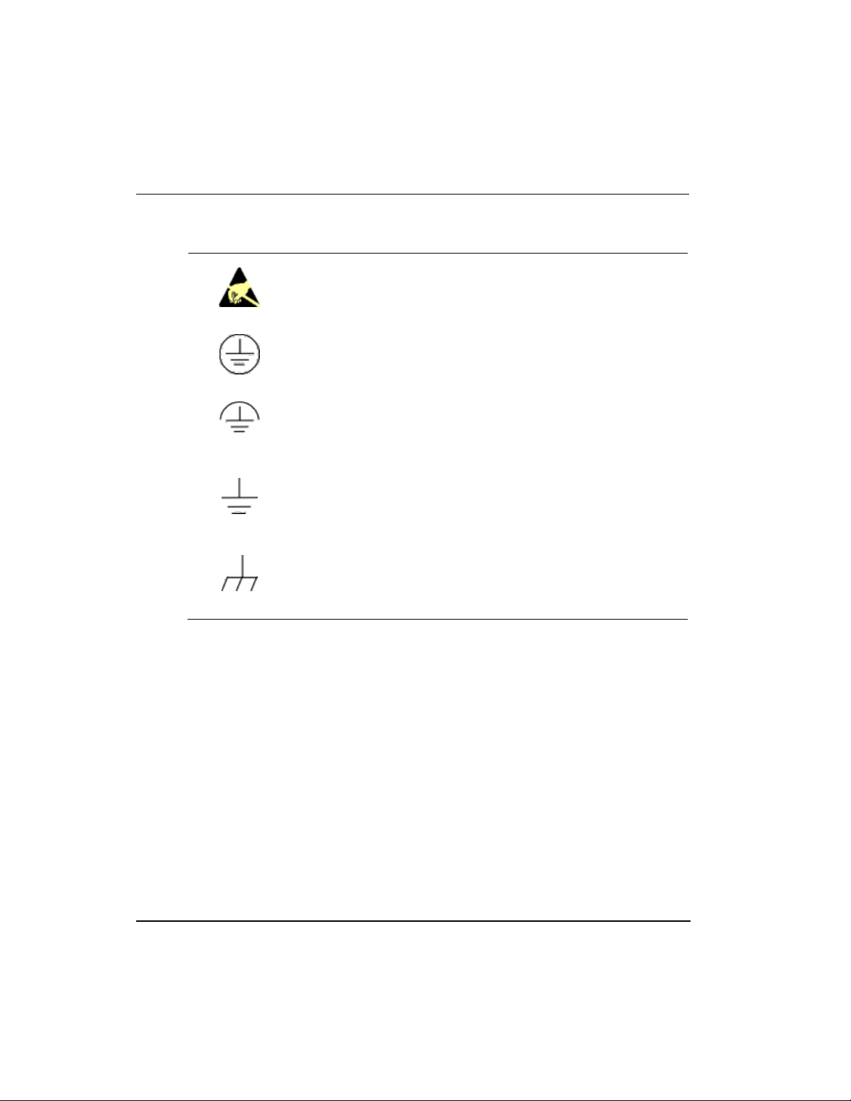
ESD HAZARD: Danger of an electro-static discharge to which
equipment may be sensitive. Observe precautions for handling
electrostatic sensitive devices.
Protective Earth (PE) terminal: Provided for connection of the
protective earth (green or green/yellow) supply system conductor.
Functional earth terminal: Used for non-safety purposes such as
noise immunity improvement. NOTE: This connection shall be
bonded to Protective Earth at the source of supply in accordance
with national local electrical code requirements.
Earth Ground: Functional earth connection. NOTE: This
connection shall be bonded to Protective Earth at the source of
supply in accordance with national and local electrical code
requirements.
Chassis Ground: Identifies a connection to the chassis or frame of
the equipment shall be bonded to Protective Earth at the source of
supply in accordance with national and local electrical code
requirements.
Symbol Definitions
viii Series 8 I/O User's Guide R500
Honeywell April 2017

Contents
1. SERIES 8 I/O PURPOSE ............................................................. 23
1.1 Overview ........................................................................................................ 23
1.2 What is I/O? .................................................................................................... 23
Series 8 I/O .......................................................................................................................... 23
2. SERIES 8 I/O PLANNING AND DESIGN ..................................... 25
2.1 Overview ........................................................................................................ 25
2.2 Series 8 I/O appearance and features ......................................................... 25
Look and feel ........................................................................................................................ 25
2.3 Series 8 I/O and C300 topology ................................................................... 27
Examining the topology rules ............................................................................................... 28
2.4 Supported Series 8 I/O modules .................................................................. 30
Available Series 8 I/O modules ............................................................................................ 30
Identifying supported Series 8 I/O modules.......................................................................... 31
2.5 Pulse Accumulation module ........................................................................ 32
What is Pulse Accumulation (Digital Input Pulse Accumulation) module ............................. 32
Features of Digital Input Pulse Accumulation ....................................................................... 32
Limitations of Digital Input Pulse Accumulation .................................................................... 32
2.6 Supported Series 8 I/O options .................................................................... 32
Available Series 8 I/O options .............................................................................................. 32
Inspecting the Series 8 I/O library ........................................................................................ 33
Inspecting IOM function blocks ............................................................................................ 33
Inspecting channel function blocks ....................................................................................... 34
Defining module containment ............................................................................................... 34
2.7 I/O Link performance specifications ........................................................... 36
Reviewing Link Unit utilization .............................................................................................. 36
Reducing I/O Link traffic ....................................................................................................... 37
Event collection .................................................................................................................... 37
PV and Back calculation scanning ....................................................................................... 37
3. SERIES 8 I/O INSTALLATION AND UPGRADES ....................... 39
3.1 Overview ........................................................................................................ 39
3.2 Installation Declarations ............................................................................... 39
Introduction .......................................................................................................................... 40
R500 Series 8 I/O User's Guide ix
April 2017 Honeywell

Contents
I/O Link Number and IOM Number DIP switch .................................................................... 40
Cabling ................................................................................................................................ 41
3.3 Installing the Series 8 IOTA on the Panel .................................................... 43
Prerequisites ....................................................................................................................... 43
Considerations .................................................................................................................... 43
Mounting the IOTA .............................................................................................................. 43
3.4 Mounting the I/O module on the IOTA ......................................................... 45
Prerequisites ....................................................................................................................... 45
Mounting the module ........................................................................................................... 45
3.5 Grounding and power considerations - IOTA boards ................................ 46
Attaching the IOTA board .................................................................................................... 46
Testing for power ................................................................................................................. 46
3.6 Connecting IOMs and field devices through I/O Termination Assemblies47
IOTAs wiring diagrams ........................................................................................................ 47
3.7 Powering the Series 8 system ...................................................................... 49
Supplying power to I/O modules.......................................................................................... 49
3.8 Fusing - Series 8 IOTA boards ..................................................................... 49
Protecting the Series 8 I/O components .............................................................................. 49
4. SERIES 8 IOTA PINOUTS ........................................................... 51
4.1 HART/Non-HART Analog Input IOTA (Models 8X-TAIXA1, 8X-TAIXB1) ... 51
Analog Input wiring .............................................................................................................. 54
4.2 Differential Analog input IOTA (Models 8X-TAIDA1 and 8X-TAIDB1) ...... 59
Compatible IOTA models for differential analog input and output channels ........................ 59
Analog Input wiring .............................................................................................................. 59
4.3 Analog Output IOTA Models 8X-TAOXA1, 8X-TAOXB1 ............................. 74
HART/Non-HART Analog Output IOTA (Models 8X-TAOXA1, 8X-TAOXB1) ...................... 79
4.4 TC/RTD IOTA Models 8X-TAIMA1 ............................................................... 80
Field wiring and module protection ...................................................................................... 81
IOTA board and connections ............................................................................................... 81
4.5 Digital Input 24V IOTA Models 8X- TDILA1, 8X- TDILB1 ............................ 85
Field wiring and module protection ...................................................................................... 85
4.6 Digital Output 24V IOTA Models 8X-TDODA1, 8X-TDODB1 ...................... 93
Field wiring and module protection ...................................................................................... 93
IOTA board and connections ............................................................................................... 93
4.7 AC Digital Output (Source) Relay Extension Board Models 8U-SDOX01,
8C-SDOX01 .............................................................................................................. 100
4.8 Upgrading firmware in Series 8 I/O components ..................................... 104
x Series 8 I/O User's Guide R500
Honeywell April 2017

Contents
5. SERIES 8 I/O CONFIGURATION FORM REFERENCE ............ 105
5.1 Overview ...................................................................................................... 105
Rules for Configuring/Reconfiguring redundant IOMs ........................................................ 105
5.2 Determining Series 8 I/O block redundancy ............................................. 107
Main tab checkbox invokes redundancy ............................................................................ 107
5.3 Switchover and Secondary readiness ...................................................... 108
5.4 Failure conditions and switchover ............................................................ 109
5.5 Configuration tools ..................................................................................... 109
Using Control Builder to create control strategies .............................................................. 109
5.6 Configuring the Main tab - IOM block ....................................................... 110
Configuring modules - Main tab ......................................................................................... 110
5.7 Status Data tab - IOM block ........................................................................ 114
Modules - Status Data tab .................................................................................................. 114
5.8 Configuring the Maintenance tab - IOM block .......................................... 116
Configuring modules - Maintenance tab ............................................................................. 116
5.9 Configuring Box Soft Failures tab - IOM block ........................................ 118
Configuring modules - Box Soft Failures tab ...................................................................... 118
5.10 Configuring Channel Soft Failures tab - IOM block ............................. 120
Configuring modules - Channel Soft Failures tab ............................................................... 120
5.11 Configuring Server History tab - IOM block .......................................... 122
Configuring modules - Server History tab........................................................................... 122
5.12 Configuring Server Displays tab - IOM block ....................................... 125
Configuring modules - Server Displays tab ................................ ........................................ 125
5.13 Configuring Control Confirmation tab - IOM block .............................. 129
Configuring modules - Control Confirmation tab ................................................................ 129
5.14 Configuring Identification tab - IOM block ............................................ 131
Configuring modules - Identification tab ............................................................................. 131
5.15 Configuring the Calibration tab - IOM block ......................................... 134
Configuring modules - Calibration tab ................................................................................ 134
5.16 Configuring HART Status tab - IOM block ............................................ 137
Configuring modules HART - Status tab ............................................................................ 137
5.17 Configuring the Configuration tab - Channel block ............................. 139
Configuring modules - Identification tab ............................................................................. 139
5.18 Configuring HART Configuration tab - Channel block ........................ 141
Configuring modules - HART Configuration tab ................................................................. 141
R500 Series 8 I/O User's Guide xi
April 2017 Honeywell

Contents
5.19 Configuring HART Device Status tab - Channel block ......................... 144
Configuring modules - Identification tab ............................................................................ 144
5.20 Configuring HART Identification tab - Channel block .......................... 146
Configuring modules - Identification tab ............................................................................ 146
5.21 Configuring HART Variables tab - Channel block ................................ 148
Configuring modules - Identification tab ............................................................................ 148
5.22 Configuring HART Notifications tab - Channel block .......................... 151
Configuring modules - Identification tab ............................................................................ 151
5.23 Configuring Dependencies tab - Channel block ................................... 153
Configuring modules - Dependencies tab ......................................................................... 153
5.24 Configuring Template Defining tab - Channel block ............................ 155
Configuring modules - Identification tab ............................................................................ 155
6. SERIES 8 I/O CONFIGURATION .............................................. 157
6.1 Adding an IOM to Project ............................................................................ 157
Using the File menu method ............................................................................................. 157
Using the drag and drop method ....................................................................................... 159
6.2 Assigning an IOM to an IOLINK in the Project tab ................................... 159
Using the Assignment dialog box ...................................................................................... 159
6.3 Adding an IOC block to a Control Module ................................................ 161
Using the Project tab drag and drop .................................................................................. 161
Using the Library tab - drag and drop ................................................................................ 163
6.4 Assigning an IOC block to an IOM ............................................................. 166
IOC block assignment ....................................................................................................... 166
6.5 Unassigning an IOC block from an IOM .................................................... 168
IOC block unassignment ................................................................................................... 168
6.6 Defining Channel blocks ............................................................................. 169
Overview ........................................................................................................................... 169
Common features of I/O channel blocks ........................................................................... 170
Defining Mode and Attribute settings ................................................................................. 170
Enabling HART.................................................................................................................. 178
Using Block Copy .............................................................................................................. 182
6.7 Defining Analog Input Channel Blocks ..................................................... 182
Overview ........................................................................................................................... 182
Determining PV Characterization ...................................................................................... 184
Determining Linear Conversion ......................................................................................... 185
Determining Square Root Conversion ............................................................................... 185
Determining Thermal Conversion ...................................................................................... 186
Checking and Filtering PV Range ..................................................................................... 187
xii Series 8 I/O User's Guide R500
Honeywell April 2017

Contents
6.8 Defining Analog Output Channel Blocks .................................................. 188
Overview ............................................................................................................................ 188
Determining Direct/Reverse Output ................................................................................... 189
Determining Output Characterization ................................................................................. 190
Determining Calibration Compensation .............................................................................. 191
Determining Modes ............................................................................................................ 191
6.9 Defining Digital Input Channel Blocks ...................................................... 191
Overview ............................................................................................................................ 191
Determining Status Digital Input channel ........................................................................... 192
Determining Latched Digital Input channel ......................................................................... 193
6.10 Defining Digital Output Channel Blocks ............................................... 193
Overview ............................................................................................................................ 193
Determining Status Output type ......................................................................................... 195
Determining Pulse Width Modulated (PWM) Output type .................................................. 195
Determining On-Pulse and Off-Pulse Output type .............................................................. 196
Determining Initialization Request Flag .............................................................................. 198
Determining Modes ............................................................................................................ 198
Determining Output Verification ......................................................................................... 198
Determining Over-current protection .................................................................................. 199
6.11 Defining DIGITAL INPUT PULSE ACCUMULATION Channel Blocks . 199
Overview ............................................................................................................................ 199
Determining the Digital Input channel properties or DIGITAL INPUT PULSE ACCUMULATION
channel properties .............................................................................................................. 200
PV Source Selection .......................................................................................................... 201
6.12 Electronic Short-Circuit Protection (Digital Output 24VDConly) ........ 201
Non-redundant Configuration ............................................................................................. 201
Redundant Configuration ................................................................................................... 202
Electronic Short-Circuit Fault Recovery ............................................................................. 203
7. SERIES 8 I/O OPERATIONS ..................................................... 205
7.1 Overview ...................................................................................................... 205
7.2 Reviewing the Control Builder icons ........................................................ 205
Series 8 I/O block icons ..................................................................................................... 205
IOLINK icons ...................................................................................................................... 207
Block icons ......................................................................................................................... 208
Channel icons .................................................................................................................... 208
7.3 Series 8 I/O LED Descriptions .................................................................... 209
7.4 Powering up the IOM .................................................................................. 212
7.5 Activating a control strategy from the Monitoring tab ............................ 214
Starting an IOM .................................................................................................................. 214
Issuing Shutdown command .............................................................................................. 215
R500 Series 8 I/O User's Guide xiii
April 2017 Honeywell

Contents
7.6 Activating HART .......................................................................................... 215
Assigning a channel to HART - Series 8 ........................................................................... 215
Enabling HART Alarm and Events - Series 8 .................................................................... 216
7.7 IOM configuration values not copied during Block Copy operation ...... 218
7.8 Sequence of Events Scenarios .................................................................. 218
Input chatter scenario ........................................................................................................ 218
PVCHGDLY scenarios ...................................................................................................... 219
PV State Change event Regeneration .............................................................................. 220
7.9 Sequence of Events Events and Configuration........................................ 221
Sequence of Events Event Configuration .......................................................................... 221
Sequence of Events Events .............................................................................................. 222
7.10 DIMODE related scenarios ...................................................................... 223
DIMODE Parameter Changes ........................................................................................... 223
Low Latency Mode ............................................................................................................ 224
7.11 Enabling point type selection in Digital Input Pulse Accumulation
channel 224
7.12 Enabling the configuration in Digital Input Pulse Accumulation channel
225
8. SERIES 8 I/O LOADING ............................................................ 227
8.1 Loading Series 8 I/O components .............................................................. 227
Load order guidelines ........................................................................................................ 227
8.2 Loading an IOLINK ...................................................................................... 228
IOLINK Load with Contents ............................................................................................... 228
8.3 Loading the IOM block the first time ......................................................... 228
Loading the IOM block present on the IOLINK .................................................................. 228
Loading with the IOM block missing on the IOLINK .......................................................... 231
Reloading the IOM block from Project or Monitoring ......................................................... 232
Reviewing IOM reconfiguration rules ................................................................................. 232
8.4 Common I/O block load activities .............................................................. 233
Uploading the I/O block ..................................................................................................... 233
Update to Project............................................................................................................... 234
Using IOM Checkpoint ...................................................................................................... 234
8.5 Loading a CM ............................................................................................... 234
Loading the CM the first time ............................................................................................ 234
Reloading the CM from Project or Monitoring ................................................................... 235
8.6 Setting Priority IOMs ................................................................................... 236
xiv Series 8 I/O User's Guide R500
Honeywell April 2017

Contents
9. SERIES 8 I/O LINK FIBER OPTIC EXTENDERS (FOE) ........... 241
9.1 Overview
Fiber Optic Extender assembly .......................................................................................... 241
FOE features ...................................................................................................................... 243
Fiber Optic redundancy ...................................................................................................... 244
....................................................................................................... 241
9.2 FOE Installation ........................................................................................... 244
Handling components - ESD .............................................................................................. 244
Work practices ................................................................................................................... 244
9.3 Component mounting sequence ............................................................... 245
Mounting the FOE module onto the IOTA .......................................................................... 246
Mounting the FOE module/back panel assembly to the carrier .......................................... 246
To mount the FOE module/back panel assembly to the carrier.......................................... 246
Connecting the IOLINK interface cable to the FOE module ............................................... 246
Connecting the fiber optic cables to the FOE module ........................................................ 247
FOE connection rules ......................................................................................................... 248
LED indicators .................................................................................................................... 249
9.4 Defining the Fiber Optic topology ............................................................. 249
FOE capacity ...................................................................................................................... 250
FOE capacity...................................................................................................................... 250
Required hardware ............................................................................................................. 250
FOE topologies .................................................................................................................. 251
Fiber optic budget considerations ...................................................................................... 252
I/O link extender cable selection ........................................................................................ 253
Allowable standard I/O Link extender cable signal loss ...................................................... 254
10. SERIES 8 I/O TROUBLESHOOTING......................................... 255
10.1 Initial checks ............................................................................................ 255
Checking Control Builder error code reference .................................................................. 255
Checking front panel display and LEDs ............................................................................. 255
Upgrading Firmware in Series 8 I/O components ............................................................... 255
10.2 Self-test diagnostics at power-up .......................................................... 256
Power-up diagnostics ......................................................................................................... 256
10.3 Communication problems ...................................................................... 257
IOLINK - loss of communications ....................................................................................... 257
IOLINK - re-establishing communications .......................................................................... 257
11. SERIES 8 I/O MAINTENANCE .................................................. 258
11.1 Series 8 recommended spares............................................................... 258
IOM removal and installation under power ......................................................................... 258
R500 Series 8 I/O User's Guide xv
April 2017 Honeywell

Contents
11.2 Replacing a Series 8 IOTA ...................................................................... 264
11.3 Replacing an I/O module ......................................................................... 264
Prerequisites ..................................................................................................................... 265
12. SERIES 8 POWER SUB-SYSTEM CONNECTIONS AND ALARM
INDICATIONS ..................................................................................... 267
12.1 Series 8 DC Power Connections and Indicators ................................... 267
12.2 Series 8 Power Sub-System Alarm Contacts and LED Activation Levels
268
13. SERIES 8 I/O ALARMS AND FAILURES ................................. 269
13.1 Reviewing IOM alarms generated by the C300 ..................................... 269
IOM alarms ........................................................................................................................ 269
HART alarms/events ......................................................................................................... 269
13.2 Reviewing IOM soft failures .................................................................... 270
IOM soft failures ................................................................................................................ 270
01 STCOVRUN .......................................................................................................... 270
06 FTAMISSG ............................................................................................................ 271
07 EECKSMER .......................................................................................................... 271
08 EECNTERR ........................................................................................................... 271
09 EEFLAGER ........................................................................................................... 271
21 INPTFAIL ............................................................................................................... 272
23 OUTPUTFL ........................................................................................................... 272
24 STCKLIM ............................................................................................................... 272
26 DIAGCTFL ............................................................................................................. 272
31 FTAMSMCH .......................................................................................................... 273
32 VZERO-FL ............................................................................................................. 273
33 BADRJVAL ............................................................................................................ 273
36 FTA1FAIL .............................................................................................................. 274
37 FTA2FAIL .............................................................................................................. 274
38 CALBABRT ........................................................................................................... 274
39 BADCALRF ........................................................................................................... 274
41 VREFFAIL ............................................................................................................. 275
42 ADOUTUDF .......................................................................................................... 275
43 ADOUTCAL ........................................................................................................... 275
44 BADFLREG ........................................................................................................... 275
45 BDSNDLTC ........................................................................................................... 275
46 BDOUTBFR ........................................................................................................... 276
47 VCALFAIL ............................................................................................................. 276
48 F1NOTCAL ............................................................................................................ 276
49 F2NOTCAL ............................................................................................................ 277
50 F1COM_FL ............................................................................................................ 277
xvi Series 8 I/O User's Guide R500
Honeywell April 2017

Contents
51 F2COM_FL ............................................................................................................ 277
52 F1_IDERR ................................................................ .............................................. 277
53 F2_IDERR ................................................................ .............................................. 277
54 F1VREFFL ............................................................................................................. 278
55 F2VREFFL ............................................................................................................. 278
56 F1CAL_FL ................................................................ .............................................. 278
57 F2CAL_FL ................................................................ .............................................. 279
58 WRITENBL ............................................................................................................. 279
60 MLTINPFL ................................................................ .............................................. 279
61 REDNDIAG ............................................................................................................ 279
63 WRONG_HW ......................................................................................................... 280
69 DTPATHFL ............................................................................................................. 280
70 DTPATHTO ............................................................................................................ 280
72 PIFAULTY .............................................................................................................. 280
161 HMODEM1 ............................................................................................................. 281
162 HMODEM2 ............................................................................................................. 281
163 HMODEM3 ............................................................................................................. 281
164 HMODEM4 ............................................................................................................. 281
165 HDIAGTO ............................................................................................................... 282
166 HSTACKHI ............................................................................................................. 282
167 FTA3FAIL ............................................................................................................... 282
168 FTA4FAIL ............................................................................................................... 282
169 F3NOTCAL ............................................................................................................ 283
170 F4NOTCAL ............................................................................................................ 283
171 F3COMFL .............................................................................................................. 283
172 F4COMFL .............................................................................................................. 283
173 F3IDERR ................................................................................................................ 283
174 F4IDERR ................................................................................................................ 284
175 F3VREFFL ............................................................................................................. 284
176 F4VREFFL ............................................................................................................. 284
177 F3CALFL ................................................................................................................ 285
178 F4CALFL ................................................................................................................ 285
179 OPENWIRE ............................................................................................................ 285
180 DOVRCRNT ........................................................................................................... 285
181 FTAPOWFL ............................................................................................................ 286
182 DPADIAFAIL .......................................................................................................... 286
183 RDBKRGDIAGFL ................................................................................................... 286
184 WDTDIAGFAIL ....................................................................................................... 286
185 RLYEXTBDMSSNG ............................................................................................... 287
186 REDHWFAIL .......................................................................................................... 287
187 HARTCHANFAIL ................................ .................................................................... 287
13.3 Reviewing IOM hard failures .................................................................. 288
IOM hard failures ................................................................................................................ 288
IOM Behavior during Hard Failures .................................................................................... 289
13.4 Getting further assistance ...................................................................... 291
Other troubleshooting sources ........................................................................................... 291
Guidelines for requesting support ...................................................................................... 291
R500 Series 8 I/O User's Guide xvii
April 2017 Honeywell

Contents
Tables
Tables
Table 1 Terms and conventions ...................................................................................... iv
Table 2 Series 8 features ............................................................................................... 25
Table 3 Topology rules ................................................................................................... 29
Table 4 Available I/O modules ....................................................................................... 30
Table 5 Series 8 I/O channel function blocks ................................................................. 34
Table 6 Link Unit utilization rates ................................................................................... 36
Table 7 I/O parameters scanned when the IOM is loaded ............................................ 37
Table 8 Series 8 I/O cable types .................................................................................... 41
Table 9 IOMs, IOTAs, and ancillary cards ..................................................................... 48
Table 10 Analog Input 6 inch, non-HART Analog Input, non-redundant - terminal block 1
................................................................................................................................ 53
Table 11 Analog Input 6 inch, HART/non-HART Analog Input, non-redundant terminal
block 2 ..................................................................................................................... 54
Table 12 Summary - Analog Input wiring connections................................................... 56
Table 13 Custom wiring to support differential Analog Input ......................................... 61
Table 14 Series 8 differential Analog Input 9 and 12 inch – terminal block 1 ................ 68
Table 15 Series 8 differential Analog Input 9 inch and 12 inch IOTAs – terminal block 268
Table 16 Jumpers to support Analog Input connections ................................................ 70
Table 17 Analog Output 6 inch, non-redundant - terminal block 1 ................................ 76
Table 18 Analog Output 6 inch, HART/non-HART Analog Output, non-redundant -
terminal block 1 ....................................................................................................... 79
Table 19 Digital Input 9 inch, non-redundant - terminal block 1 .................................... 87
Table 20 Digital Input 9 inch, non-redundant - terminal block 2 .................................... 88
Table 21 Digital Input 9 inch, non-redundant - terminal block 3 .................................... 89
Table 22 24V Digital Output 9 inch, non-redundant - terminal block 1 .......................... 95
Table 23 24V Digital Output 9 inch, non-redundant - terminal block 2 .......................... 96
Table 24 24V Digital Output 9 inch, non-redundant - terminal block 3 .......................... 97
Table 25 AC Digital Output (Source) Relay Extension Board - terminal block 1 ......... 100
Table 26 AC Digital Output (Source) Relay Extension Board - terminal block 2 ......... 101
Table 27 Redundancy state and module readiness ..................................................... 108
Table 28 Failure conditions and switchover ................................................................. 109
Table 29 Main tab parameters ..................................................................................... 112
Table 30 Server History tab parameters ...................................................................... 124
Table 31 Server Display tab parameters ..................................................................... 127
Table 32 Identification tab parameters ......................................................................... 132
Table 33 HART Configuration tab parameters ............................................................. 142
Table 34 HART Device Status tab parameters ............................................................ 145
Table 35 HART Identification tab ................................................................................. 147
Table 36 HART Variables tab parameters ................................................................... 150
Table 37 HART Notifications tab parameters .............................................................. 152
R500 Series 8 I/O User's Guide xviii
April 2017 Honeywell

Contents
Tables
Table 38 I/O Channel block type ................................................................................. 170
Table 39 Mode parameter - channel block .................................................................. 171
Table 40 Mode Attribute parameter - channel block ................................................... 171
Table 41 Channel block fault conditions and results ................................................... 172
Table 42 Analog Output fault handling ........................................................................ 173
Table 43 Digital Output fault handling ......................................................................... 174
Table 44 FAULTOPT parameter settings .................................................................... 175
Table 45 IOM hard failure and output state ................................................................. 176
Table 46 PV Source settings ....................................................................................... 177
Table 47 PVSRCOPT settings .................................................................................... 177
Table 48 REDTAG settings ......................................................................................... 177
Table 49 HART parameters ......................................................................................... 182
Table 50 Analog Input engineering unit conversions .................................................. 184
Table 51 RTD lead wire characteristics ....................................................................... 186
Table 52 Status Output settings .................................................................................. 197
Table 53 Setting DOTYPE to ONPULSE or OFFPULSE ............................................ 197
Table 54 Digital Output channel initialization .............................................................. 198
Table 55 Channel block icons ..................................................................................... 205
Table 56 IOLINK icons ................................................................................................. 207
Table 57 Block icons .................................................................................................... 208
Table 58 Channel icons ............................................................................................... 208
Table 59 I/O LED descriptions ..................................................................................... 211
Table 60 Sequence of activating components - Monitoring tab .................................. 214
Table 61 Sequence of activating components - Project tab ........................................ 227
Table 62 IOM reconfiguration rules ............................................................................. 233
Table 63 FOE module and back panel summary ........................................................ 242
Table 64 FOE LED descriptions .................................................................................. 249
Table 65 Recommended spare parts .......................................................................... 258
Table 66 IOM alarms displayed by the C300 controller .............................................. 269
Table 67 IOM hard failures .......................................................................................... 290
R500 Series 8 I/O User's Guide xix
April 2017 Honeywell

Contents
Figures
Figures
Figure 1 Series 8 I/O and C300 topology ....................................................................... 28
Figure 2 Series 8 I/O library ........................................................................................... 33
Figure 3 Execution State ................................................................................................ 35
Figure 4 Point Execution State ....................................................................................... 35
Figure 5 Series 8 board connections ............................................................................. 40
Figure 6 Series 8 cabling ............................................................................................... 42
Figure 7 IOLINK’s terminal on the header board for power testing ............................... 47
Figure 8 Series 8 HART/non-HART Analog Input 6 inch, non-redundant IOTA ............ 52
Figure 9 Non-redundant Analog Input 9 inch, standard 2-wire transmitter wiring ......... 55
Figure 10 Series 8 HART/non-HART Analog Input 12 inch, redundant IOTA ............... 58
Figure 11 Non-redundant Analog Input 9 inch, standard 2-wire transmitter wiring ....... 60
Figure 12 Non-redundant Analog Input 9 inch, self-powered 2-wire transmitter wiring . 60
Figure 13 Series 8 differential non-redundant Analog Input 9 inch, jumper configuration65
Figure 14 Series 8 differential redundant Analog Input 12 inch, jumper configuration .. 66
Figure 15 Series 8 differential Analog Input 9 inch, non-redundant IOTA ..................... 67
Figure 16 Series 8 differential Analog Input 12 inch, redundant IOTA .......................... 74
Figure 17 Series 8 Analog Output 6 inch, non-redundant IOTA .................................... 75
Figure 18 Series 8 Analog Output 6 inch, non-redundant IOTA and field wiring connection
................................................................................................................................ 77
Figure 19 Series 8 Analog Output 12 inch, redundant IOTA ......................................... 78
Figure 20 Series 8 TC/RTD 6 inch, non-redundant IOTA .............................................. 82
Figure 21 Series 8 TC/RTD IOTA and field wiring connections ..................................... 83
Figure 22 Series 8 24V Digital Input 9 inch, non-redundant IOTA ................................. 86
Figure 23 Series 8 24V Digital Input 9 inch, non-redundant IOTA and field wiring
connection ............................................................................................................... 90
Figure 24 Series 8 24V Digital Input 12 inch, redundant IOTA ...................................... 91
Figure 25 Series 8 24V Digital Output 9 inch, non-redundant IOTA .............................. 94
Figure 26 Series 8 24V Digital Output 9 inch, non-redundant IOTA and field wiring
connections ............................................................................................................. 98
Figure 27 Series 8 24V Digital Output 12 inch, redundant IOTA ................................... 99
Figure 28 Series 8 AC Digital Output (Source) Relay Extension Board ...................... 100
Figure 29 Series 8 AC Digital Output (Source) Relay Extension Board and field wiring
connections ........................................................................................................... 103
Figure 30 Defining redundancy from the Main tab ....................................................... 108
Figure 31 Main tab ....................................................................................................... 111
Figure 32 Status Data tab ............................................................................................ 115
Figure 33 Maintenance tab .......................................................................................... 117
Figure 34 Box Soft Failures tab .................................................................................... 119
Figure 35 Channel Soft Failures tab ............................................................................ 121
Figure 36 Server History tab ........................................................................................ 123
xx Series 8 I/O User's Guide R500
Honeywell April 2017

Contents
Figures
Figure 37 Server Display tab ....................................................................................... 126
Figure 38 Control Confirmation tab ............................................................................. 130
Figure 39 Identification tab .......................................................................................... 132
Figure 40 Calibration tab ............................................................................................. 135
Figure 41 HART Status tab ......................................................................................... 138
Figure 42 Configuration tab ......................................................................................... 140
Figure 43 HART Configuration tab .............................................................................. 142
Figure 44 HART Device Status tab ............................................................................. 145
Figure 45 HART Identification tab ............................................................................... 147
Figure 46 HART Variables tab ..................................................................................... 149
Figure 47 HART Notifications tab ................................................................................ 152
Figure 48 Dependencies tab ....................................................................................... 154
Figure 49 Template Defining tab ................................................................................. 156
Figure 50 Analog Output and Digital Output fault state (FAULTST) transitions .......... 173
Figure 51 Series 8 I/O Analog Input or Analog Output withHART tabs ....................... 181
Figure 52 Analog Input conversion .............................................................................. 183
Figure 53 Analog Output conversion ........................................................................... 189
Figure 54 Determining fixed endpoint .......................................................................... 190
Figure 55 Digital input conversion ............................................................................... 192
Figure 56 Digital output conversion ............................................................................. 194
Figure 57 Pulse Width Modulated Output .................................................................... 196
Figure 58 On-Pulse and Off-Pulse Output types ......................................................... 196
Figure 59 DIGITAL INPUT PULSE ACCUMULATION conversion ............................. 200
Figure 60 Series 8 I/O LED indicators ......................................................................... 210
Figure 61 : Sequence of Events PV Change Delay Scenario ..................................... 220
Figure 62 Loading the IOM block the first time ............................................................ 229
Figure 63 Reloading the IOM block ............................................................................. 232
Figure 64 Loading the CM ........................................................................................... 235
Figure 65 Setting Priority IOM ..................................................................................... 237
Figure 66 FOE assembly ............................................................................................. 242
Figure 67 Example of possible FOE usage ................................................................. 250
Figure 68 Typical dc power and power control module connections in Series 8 cabinet
with RAM Charger 51454475-100 ........................................................................ 267
Figure 69 Location of hard failure message ................................................................ 288
R500 Series 8 I/O User's Guide xxi
April 2017 Honeywell


1. Series 8 I/O Purpose
1.1 Overview
Series 8 I/O modules, along with I/O Termination Assemblies (IOTAs), perform module
diagnostics input and output scanning and processing on all field I/O data and events. To
allow a more efficient use of Controller resources, I/O processing is performed separately
from control processing functions so that:
I/O sample rates are completely independent of I/O quantity, controller loading,
processing, and alarming
Allows more efficient use of advanced Control Processor capability, and
Provides for future I/O expansion
1.2 What is I/O?
Series 8 I/O
The Experion Series 8 I/O modules are an expanding family of traditional and special
function input/output signal interface devices. They support local software configuration.
These I/O modules share the same form factor as the C300 Controller and reside on the
same type of common mounting system as other Series 8 components.
R500 Series 8 I/O User's Guide 23
April 2017 Honeywell


I/O module/IOTA
Feature/function
Analog Input w/HART
Extensive self-diagnostics
Optional redundancy
HART capable, multivariable instruments
Fast (50 ms) loop scan
Analog Input
Extensive self-diagnostics
Optional redundancy
Fast (50 ms) loop scan
2. Series 8 I/O Planning and Design
2.1 Overview
This guide is intended to provide general information to assist you in planning and
designing the installation of your Experion Series 8 I/O.
2.2 Series 8 I/O appearance and features
Look and feel
The layout of Series 8 components supports enhanced heat management.
The features of Series 8 I/O include:
1. IOL – Each C300 I/O Link can be configured to provide 750 kbps link speeds.
2. Series 8 I/O fully supports HART I/O. This includes the use of Secondary
HART Variables as control parameters.
3. Series 8 Permits Division 2/Zone 2 mounting of the Controller and I/O.
IO Module design - tilted 18 degrees off center:
allows for efficient field wiring
Combination of I/O Module and Field terminations in the same area. The I/O
Module is mounted on the IOTA which reduces cabinet space and eliminates items.
Redundancy is performed directly on the IOTA by simply adding a second IOM to
the IOTA (with the exception of the C300 controller).
For complete feature/functions for the following modules/IOTAs, refer to the Experion
Series 8 I/O Specification and Technical Data document.
R500 Series 8 I/O User's Guide 25
April 2017 Honeywell
Table 2 Series 8 features

2. Series 8 I/O Planning and Design
I/O module/IOTA
Feature/function
Analog Output
withHART
Extensive self-diagnostics
Optional redundancy
HART capable, multivariable instruments
Safe-state (FAILOPT) behaviors
Each channel can be configured to HOLD LAST
VALUE, or SHED to a SAFE VALUE.
Analog Output
Extensive self-diagnostics
Optional redundancy
Safe-state (FAILOPT) behaviors
Each channel can be configured to HOLD LAST
VALUE, or SHED to a SAFE VALUE.
Digital Input 24VDC
Extensive self-diagnostics
IOM redundancy
Input direct/reverse
Internal or external field power selections
Galvanic isolation
Low Latency / High Speed Scanning mode
Digital Input
Sequence of Events
DIGITAL INPUT
SEQUENCE OF
EVENTS
Extensive self-diagnostics
Optional redundancy
1ms Sequence of Events for Discrete Inputs
Low Latency / High Speed Scanning mode
On board excitation power (no need for marshalling
power)
Direct / Reverse Input Indication
Galvanic isolation
2.2. Series 8 I/O appearance and features
26 Series 8 I/O User's Guide R500
Honeywell April 2017

2. Series 8 I/O Planning and Design
I/O module/IOTA
Feature/function
Digital Output 24Vdc
Extensive self-diagnostics
Functional redundancy
Output direct/reverse
Safe-state (FAILOPT) behaviors
Each channel can be configured to HOLD LAST
VALUE, or SHED to a SAFE VALUE.
Fuse-less short circuit protection allows a short circuit to
exist without blowing any fuses. When a particular
channel is shorted, internal circuits detect this and remove
power to the field connection. The channel remains deenergized until the short circuit is repaired.
Latched, pulsed or pulse-width modulated output
Galvanic isolation
Output read back checking to screw terminal
TC/RTD
TC and RTD operation
Remote cold junction capability
1 sec PV scanning with OTD protection
Configurable OTD protection (See below)
Temperature points can be added in 16 point increments
Digital Input Pulse
Accumulation module
Extensive self-diagnostics
IOM redundancy
Input direct/reverse for Digital Input channels
Internal or external field power selections
Galvanic isolation
PV processing or Pulse Accumulation functionality based
on the user configuration.
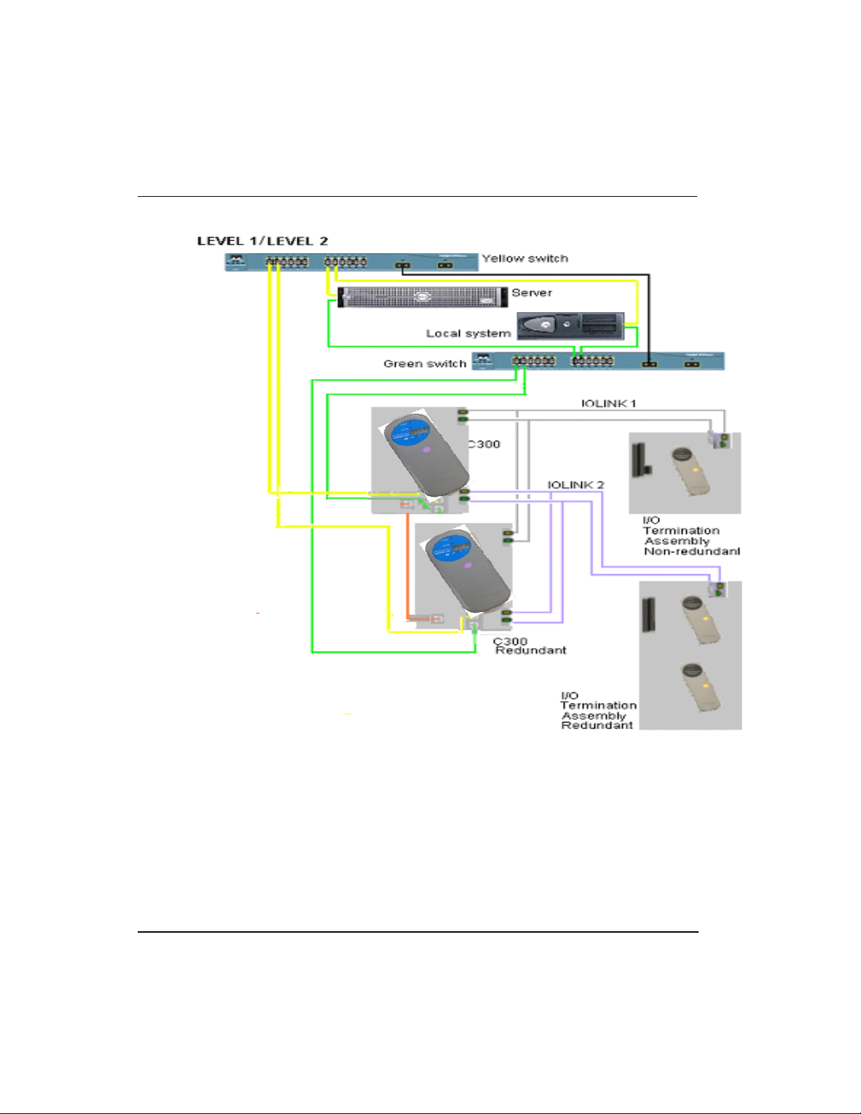
2.3. Series 8 I/O and C300 topology
2.3 Series 8 I/O and C300 topology
Series 8 I/O is attached to an IOLINK that is being mastered by a C300 controller. It is
important to note that the IOLINK serves as data repository for IOM function blocks in
R500 Series 8 I/O User's Guide 27
April 2017 Honeywell
Control Builder to provide communications interface with Series 8 I/O.
2. Series 8 I/O Planning and Design
2.3. Series 8 I/O and C300 topology
Figure 1 Series 8 I/O and C300 topology
Examining the topology rules
The following table provides the topology rules relating to the Series 8 I/O environment.
28 Series 8 I/O User's Guide R500
Honeywell April 2017

2. Series 8 I/O Planning and Design
Item
Impact
Description
Redundancy
None
Redundancy capacity and performance is
displayed while redundancy is present.
Switchover
None
Series 8 I/O hardware and/or software can
switchover, recover, and resume full view.
Initialization
All Series 8 I/O
per C300
Can be initialized in 60 seconds (+/- 25%) after
cabinet-level loss power loss.
1 I/O module
Can be initialized in 10 seconds (+/- 25%) after
IOM level loss power loss.
Multiple I/O Links
2
Design allows the use of multiple Series 8 I/O
Links in the same cabinet.
I/O Link performance
None
I/O Link networks perform at the current
distance.
I/O Link capacity
40 max
Maximum of 40 redundant IOMs per link.
IOMs / C300
80 max
Maximum of 80 redundant IOMs per C300,
using both links.
2.3. Series 8 I/O and C300 topology
Table 3 Topology rules
R500 Series 8 I/O User's Guide 29
April 2017 Honeywell
2. Series 8 I/O Planning and Design
TIP
C300 IOLINK block parameter IOLINKTYPE is used to determine if the
IOLINK supports Series 8 I/O.
IOM model
names
IOM block
name
Description
# of
channels
8C-PAIHA1
8U-PAIHA1
ANALOG
INPUT WITH
HART
Analog Input with HART- Single Ended
16
8C-PAIH54
8U-PAIH54
ANALOG
INPUT WITH
HART
Analog Input with HART - Differential
16
8C-PAINA1
8U-PAINA1
ANALOG
INPUT
Analog Input – Single Ended
16
8C-PAONA1
8U-PAONA1
Analog Output
Analog Output
16
8C-PAOHA1
8U-PAOHA1
Analog Output
Analog Output with HART
16
8U-PAIMA1
8C-PAIMA1
TC/RTD
TC/RTD input
16
8U-PDILA1
8C-PDILA1
DIGITAL
INPUT 24VDC
Digital Input (24 volts DC)
32
2.4. Supported Series 8 I/O modules
2.4 Supported Series 8 I/O modules
Available Series 8 I/O modules
The list of I/O modules below can be used on a Series 8 IOLINK. The IOLINK contains
a function that enables programming and reprogramming the executable image (rather
than substitution of a removable hardware component). The preferred method of delivery
of the image is over the IOLINK.
Table 4 Available I/O modules
30 Series 8 I/O User's Guide R500
Honeywell April 2017
 Loading...