

Page 1
Description
Part Number
Quantity
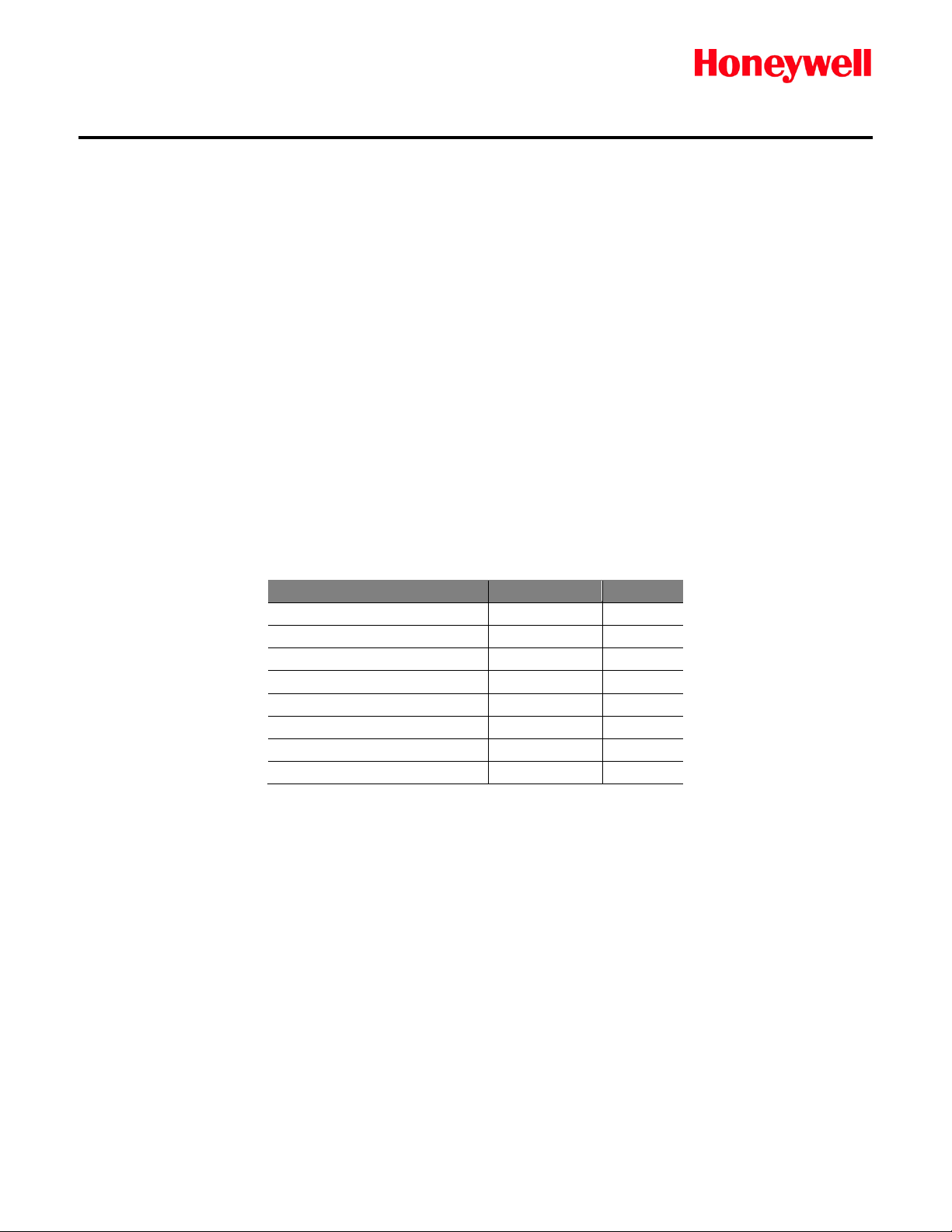
Sensor Duct Adapter
1283-1048
1
Flow Restrictor
1283-1091
1
Washer, #8 Nylon
0950-0079
2
Gasket, #8 Sealing
105637
2
Screw, 8 x ¾, self-tapping
0950-0080
2
O-ring, 7/8 I.D. x 1-1/8 O.D.
0235-1135
2*
O-ring, Sensor
0235-1130
2*
O-ring, Sensor
0235-1131
2*
Duct Mount Adapters
1998-0880 Rev 1
2014
Technical Note
September
For Duct Mounting XCD-RTD, XCD-RFD, Sensepoint Toxic,
Sensepoint Combustible, 705 and XNX w/705
Duct Mounting Kit 1283-1047
The duct mounting assembly allows installation of sensors directly into ducts with diameters from 3 to 16
inches (8 to 40 cm). The installation uses a minimum number of holes drilled into the ductwork, and
allows quick changeover for exchanging sensors. (Refer to Figure 1)
This technical note provides installation instructions for mounting the sensor duct adapter. A hole
diagram is shown in Figure 3 .
The duct mounting adapter assembly is designed to divert 700cc of sample flow to a sensor over a wide
variety of duct diameters and flow rates. For installations with high flow rates, an adjustable flow
restrictor (included) is attached to the duct adapter. Use the charts (Table 1) to determine the restrictor
settings. The restrictor adjustment settings are shown in Figure 2.
The duct mounting kit (P/N 1283-1047) includes the following:
*Only one item is required; kit contains a spare of this part.
Technical Note 1998-0880
Page 1 of 7
Page 2

Technical Note
Figure 1 – Duct Mounting Adapter
Installation
Use the chart shown in Table 1 to determine if you need to add the flow restrictor to the duct adapter.
If you need the restrictor, install it onto the pitot tubes (the portion of the duct adapter that goes into
the duct). Refer to Figure 2. The pitot tubes have scribed lines which represent Restrictor Lines A
through C. Restrictor Line C offers the most restriction, and is the line closest to the end of the pitot
tubes. Align the chamfered edge of the restrictor with the proper line before tightening the set screw.
Also, make certain the set screw is downstream of the air flow.
Figure 2 – Setting the Flow Restrictor
Technical Note 1998-0880
Page 2 of 7
Page 3
Caution:
insulators provided in this kit.
2.50 Inches (63.5 mm)
Screw mounting holes
must be parallel with
airflow +/- 5°.
7/8 - inch
(22 mm)
9/64 - inch
(3.6 mm)
NOTE: This drawing is NOT TO SCALE
1/4-inch tubing is required, and the total length should be less than 2 feet.
Adjust the position of the restrictor until the flow is 700 cc/min, +/- 100 cc/min.
Pressure drop differential:
0.3 inches H20
Duct Wall
Mass Flowmeter
(Sierra Instruments, Inc Model
822-13-OV1-PV1-V1 or equiv)
Technical Note
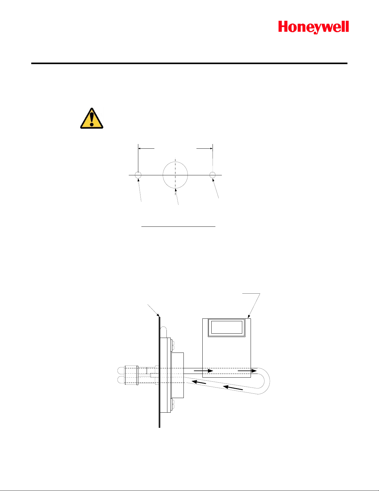
Duct mounting is simple. Figure 3 shows the hole pattern. One 7/8-inch (22 mm) hole and two smaller
9/64-inch (3.6 mm) holes for #8 sheet metal screws are the only installation intrusion to the ductwork.
The sheet metal screw holes must be parallel within +/- 5° of the direction of air flow in the duct.
To prevent an earth loop, ensure the duct adapter center does
not come in contact with metal ductwork. Use the O-rings and
Figure 3 – Hole Diagram for Duct Mounting Adapter
If the flow in the duct is not known, you must connect a mass flowmeter to the duct adapter as shown in
Figure 4. Do not use a rotometer or ballmeter.
Important:
Figure 4 – Connecting a Mass Flowmeter to Duct Adapter
Technical Note 1998-0880
Page 3 of 7
Page 4

Sample transport time:
30 seconds or less
Sample flow rate:
0.6 – 1.2 Liters per minute
Minimum:
735 ft/min (224 m/min)
Maximum:
1024 ft/min (312 m/min)
Pipe flow:
Refer to Tables 1and 2
Accuracy:
+/- 10%
Technical Note
Connecting/Changing Sensors
When changing a duct-mounted sensor, twist the sensor counterclockwise 1/4-turn to release. Reinstall per manual instructions.
Flow Performance
Velocity
Duct Mount Adapter 1283-1084
Overview
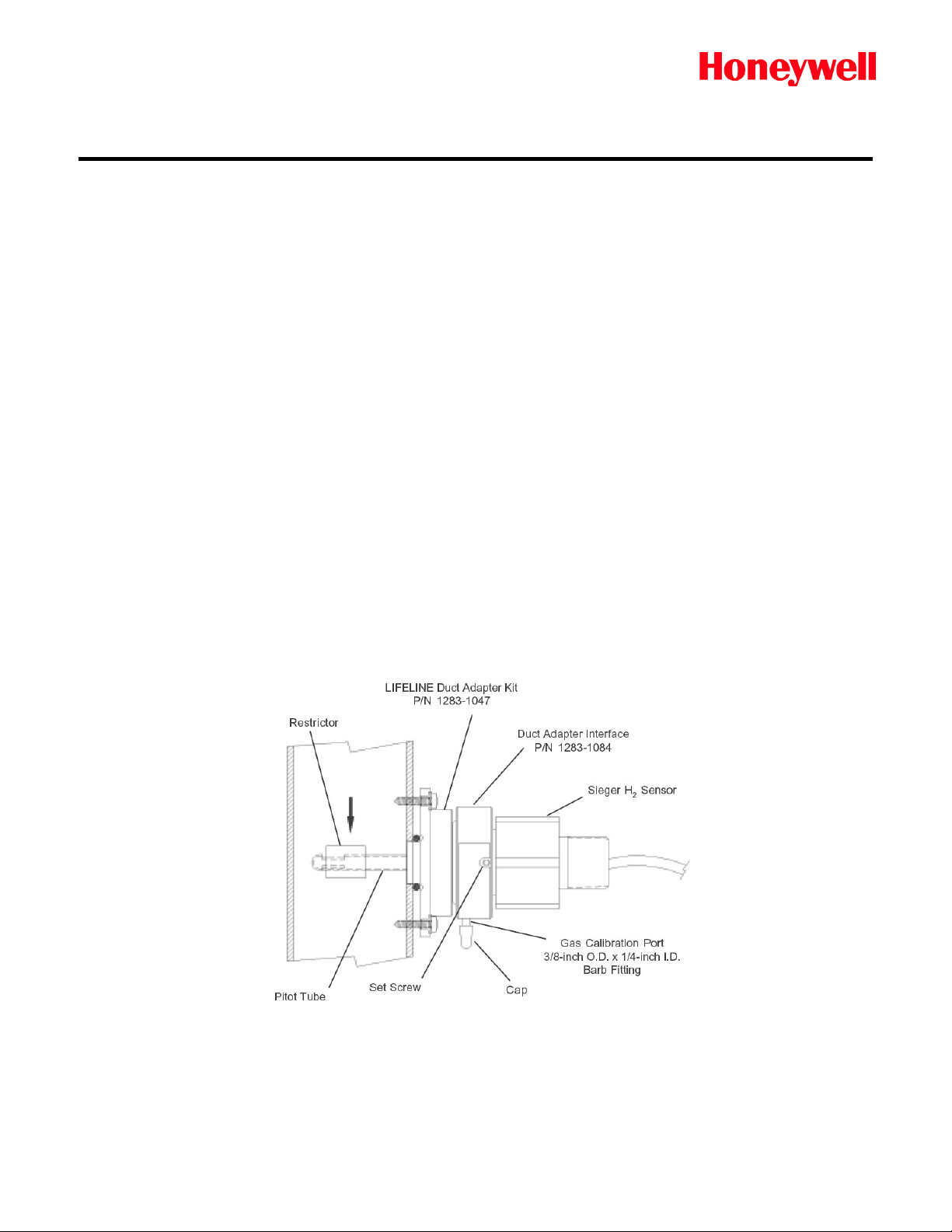
This adapter is an interface between duct adapter kit (P/N 1283-1047 described above) and the XCDRFD, Sensepoint Combustible, 705 and XNX w/705 Detectors. The adapter includes a calibration port
to allow gas testing. The adapter is shown in Figure 5.
How it Works
The adapter is a mechanical interface with the Sensor-style bayonet fitting on one end. This attaches
directly to the sensor duct adapter. The other end of the adapter interface is threaded to mate with the
XCD-RFD, Sensepoint Combustible, 705 and XNX w/705 sensors. A port on the side of the adapter
allows direct attachment to tubing for calibration or live-gas challenges.
Figure 5 – Adapter Interface
Duct Flow Rate
The duct mounting adapter kit (1283-1047) is designed to divert sample flow to a sensor over a wide
variety of duct diameters and flow rates. For installations with high flow rates, an adjustable flow
restrictor (included) is attached to the duct adapter. Use the charts (Table 2) to determine the restrictor
settings for use with the interface adapter and the hydrogen sensor.
Technical Note 1998-0880
Page 4 of 7
Page 5
Technical Note
Catalytic sensors are passive and they require no airflow for accurate and rapid gas response. Sensor
airflow of 5 to 500 cc/min is required to ensure sufficient gas changeover inside the duct adapter. The
orifice restrictor is used to limit the sensor airflow, in order to minimize the dilution of calibration gas t hat
is introduced from the side port.
Refer to the duct adapter for XCD-RTD and Sensepoint Toxic Sensors shown above for more
information about the restrictor settings. The restrictor adjustment settings are shown in Figure 2 of the
duct adapter technical note.
Installation
The duct adapter should be preinstalled in the ductwork. If it is not, refer to the instructions provided with
the duct adapter for XCD-RTD and Sensepoint Toxic Sensors shown above.
Follow the preparation and installation instructions provided with the hydrogen sensor. Make certain the
protective cap over the sensor inlet is removed before installation.
Ensure that the O-ring is in place on the threaded side of the adapter interface. Attach the threaded end
of the adapter interface to the hydrogen sensor. Tighten the set screw on the adapter interface to
secure the sensor.
Make certain that all the duct adapter O-rings are in place around the base of the center pitot tube.
Insert the interface/sensor combination into the duct adapter. A clockwise one-quarter turn secures the
components.
Figure 6 shows the completed assembly installed in a duct.
Figure 6 – Installed Assembly
Technical Note 1998-0880
Page 5 of 7
Page 6

Duct Adapter Restrictor Settings for Sensepoint and XCD-RTD Electrochemical Senso rs
Duct Flow Rate (CFM)
Not
Recommended*
3 Inches
<15
15-50
50-75
75-100
100-130
4 inches
< 65
65-90
90-130
130-180
180-220
6 inches
< 145
145-200
200-300
300-400
400-500
8 inches
< 260
260-360
360-500
500-725
725-875
10 inches
< 400
400-560
560-800
800-1125
1125-1400
12 inches
< 575
575-800
800-1200
1200-1600
1600-2000
14 inches
< 790
790-1100
1100-1550
1550-2200
2200-2700
16 inches
<1025
1025-1430
1430-2000
2000-2900
2900-3500
Duct Adapter Restrictor Settings for XCD-RFD, 705, Sensepoint Combustible, and XNX w/705 Sensors
Duct Flow Rate (CFM)
Not
Recommended
3 Inches
<10
10-50
50-75
75-100
100-130
4 Inches
<25
25-90
90-130
130-180
180-220
6 Inches
<50
50-200
200-300
300-400
400-500
8 Inches
<90
90-360
360-500
500-725
725-875
10 Inches
<140
140-560
560-800
800-1125
1125-1400
12 Inches
<200
200-800
800-1200
1200-1600
1600-2000
14 Inches
<275
275-2000
2000-1550
1550-2200
2200-2700
16 Inches
<360
360-1430
1430-2000
2000-2900
2900-3500
Technical Note
Gas Calibration and Challenges
• Remove the cap on the interface adapter gas port.
• Connect and secure tubing from calibration gas bottle’s regulator. The regulator should deliver 1
L/min.
• Open the gas valve on the calibration gas bottle to apply gas. Leave the gas on for 30 seconds
to allow the sensor to stabilize.
• Calibrate the transmitter and/or controller.
• Shut off the calibration gas.
• Remove tubing and replace the cap on the adapter’s gas calibration port.
Duct Adapter Restriction Setting Tables
Duct Diameter
* Consult Honeywell Analytics for recommendation.
Table 1 – Determining Restrictor Settings
Duct
Diameter
No Restrictor Set to Line A Set to Line B Set to Line C
No Restrictor Set to Line A Set to Line B Set to Line C
* Low flow rates cause a delay in gas response. Consult Honeywell Analytics for flows under the recommended minimums.
Table 2 – Determining Restrictor Settings
Technical Note 1998-0880
Page 6 of 7
Page 7

Technical Note
www.honeywellanalytics.com
Contact Honeywell Analytics:
Toll free: +1 800 538 0363
detectgas@honeywell.com
Europe, Middle East, Africa
Life Safety Distribution AG
Fax: +41 (0)44 943 4398
gasdetection@honeywell.com
Honeywell Analytics Asia Pacific
#508, Kolon Science Valley (I)
187-10 Guro-Dong, Guro-Gu
Fax: +82 (0)2 2025 0329
analytics.ap@honeywell.com
ha.us.service@honeywell.com
Data may change, as well as legislatio n, and you are strongly advised to obta in copies of the most recently issued regulations, standards and guideline s.
This publication is not intended to for m the basis of a contract and t he company reserves the right to am end the design and specification wit hout notice.
While every effort has been made to en sure accuracy in this publication, n o responsibility can be accepted for errors or omi ssions.
Find out more
Americas
Honeywell Analytics Inc.
405 Barclay Blvd.
Lincolnshire, IL 60069
USA
Tel: +1 847 955 8200
Fax: +1 847 955 8210
Javastrasse 2
8640 Hegnau
Switzerland
Tel: +41 (0)44 943 4300
Asia Pacific
Seoul, 152-050
Korea
Tel: +82 (0)2 2025 0307
Technical Services
www.honeywell.com
Technical Note 1998-0880
Page 7 of 7
 Loading...