

Honeywell SEC-H-INT-KP Installation Instructions Manual
SEC-H-INT-KP SmartKey
This document covers the mounting and wiring of the SEC-HINT-KP remote intrusion arming display/keypad (SmartKey) in
a Honeywell Security Appliance system, hosted by a security
controller (SEC-H-201 or SEC-H-600 model controller).
Description
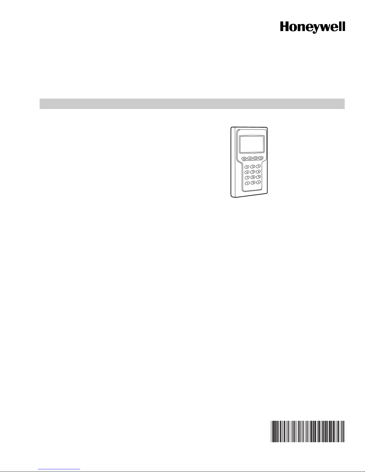
The SEC-H-INT-KP is a remote intrusion display/keypad used
to arm, disarm, and monitor intrusion zones. The integral
graphic LCD display features a white backlight, and 128 X 64
resolution. The keypad features a blue backlight, 4 function
keys, and 12 data keys.
INSTALLATION INSTRUCTIONS
SMARTKEY
OVERALL DIMENSIONS
IN INCHES AND (MM):
HEIGHT: 5.12” (130)
WIDTH: 3.23” (82)
DEPTH: 0.83” (21)
COLOR: SILVER GREY
MATERIAL: ABS
Notes
• This device is intended for installation in secure indoor
locations only. Operating temperature range is 14°F to
131°F (-10°C to 44°C).
• Power this device using the 12 VDC reader output of the
SEC-H-201, SEC-H-600, or SEC-H-R2R reader expansion
module. Device current draw is 150mA. See the
“Estimating Power and Battery Requirements” section in
the installation guide for the security controller to determine
power supply, battery, and cable requirements.
• Communication to the SmartKey device is via an RS-485
port wired to an NPB-2X-485 option card installed in the
Option Card 2 slot of the security controller. Refer to the
NPB-2X-485 Option card installation sheet for details. Note
that the SmartKey does NOT communicate on the same
RS-485 bus as the SEC-H-R2R and SEC-H-RIO modules.
• A maximum of 10 SmartKeys may be installed per security
controller.
Not covered in this document is the setup and operation of
installed SEC-H-INT-KP SmartKeys. Refer to the WEBs AX
Security Controller User's Guide (number 74-4062) for this
information.
For all other related mounting and wiring details, refer to the
appropriate mounting and wiring document. See “Related
Documentation” on page 3.
M27319
Fig. 1. SEC-H-INT-KP SmartKey.
Included in this Package
Included in this package you should find the following items:
• an SEC-H-INT-KP SmartKey, with removable mounting
backplate.
• This document SEC-H-INT-KP SmartKey Installation
Instructions, Number 62-0272.
Material and Tools Required
The following supplies and tools are required for installation:
• Small wire nuts, for making wiring terminations to
SmartKey terminals.
• Suitable tools for installing wall fasteners and preparing
wires for connections.
Recommended Cable Types
The following cable types are recommended for wiring
between an SEC-H-INT-KP SmartKey and the security
controller or SEC-H-R2R module (see Figure 4 on page 3):
• RS-485 data communications: Belden 9501 (1 pair) or
9502 (2 pair), 24AWG shielded twisted-pair, or equivalent.
• 12Vdc power: Belden 9154, 1 pair 20AWG shielded
twisted-pair, or equivalent.
62-0272-01
SEC-H-INT-KP SMARTKEY
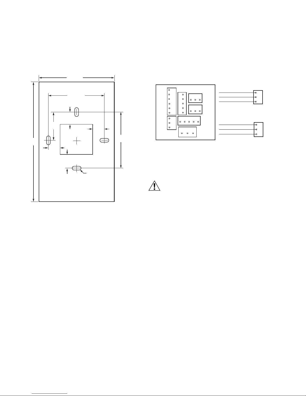
MOUNTING
Mount the SEC-H-INT-KP backplate onto a wall junction box,
with wiring cable(s) passed through center opening. See
Figure 2 for dimensions.
3-5/32 (80)
2-23/64 (60)
31/64
31/64
(12)
(12)
31/64
(12)
Ø 1/64 (4)
2-23/64
(60)
M27320
5
(127)
1-3/16
(30)
31/64
(12)
Fig. 2. SEC-H-INT-KP backplate dimensions.
Fasten with the appropriate screws into the mounting slots.
WIRING
Only two connectors on the back of the SEC-H-INT-KP
(Figure 3) are used: J1 (Power) and J5 (RS-485 comm).
6
J4
1
5
4
J3
J2
2
3
3
4
2
5
1
3
45
2
1
1
2
3
J5
1
2
3
J6
1
2
3
J7
123
J1
J5 DATA
(SHIELD) EARTH
(GREEN) DATA (–)
(YELLOW) DATA (+)
J1 POWER
(YEL/GRN) EARTH GND
(BLACK) GND
(RED) + 12V-15 VDC
3
2
1
3
2
1
M27321
Fig. 3. Connector Detail, Rear View of SEC-H-INT-KP.
Connectors have pre-attached leads—make wiring
terminations to leads using small wire nuts. Lead colors are
shown (in parenthesis) in Figure 3.
CAUTION
Electrical Shock Hazard
Before making wiring terminations, remove power
from the security controller or SEC-H-R2R module.
Restore power only after making all wiring
terminations and fastening the SEC-H-INT-KP
SmartKey unit onto its mounted backplate.
Note that up to 10 SEC-H-INT-KP SmartKey units are
supported, where RS-485 wiring from the security controller
(NPB-2X-485 option card) is “daisy-chained” at the data J5
connector on each SmartKey. For any SmartKey installed on
either end of this RS-485 buss, set its EOL Resistor JUMPER
1 to the ON position.
62-0272—01 2
Wire 12VDC power to the unit from the reader input of the
security controller, or if closer, the reader input of an SEC-HR2R module. Use shielded, twisted-pair cabling for all wiring,
with the shield continuously connected and grounded to earth
at one point only. See “Recommended Cable Types,” page 1.
 Loading...