

SEC-H-600 Security Controller
INSTALLATION INSTRUCTIONS
This document covers the mounting and wiring of the WEBs-AX® Security Controller.
It assumes that you are an engineer, technician, or service person who is performing
access system design or installation. Instructions apply to the following models:
Models Description
SEC-H-600 Security Controller base unit controller, referred to in this
document as a “Security Controller.”
NOTE: Another Security Controller model is available (SEC-H-201), which has the same form factor and onboard security I/O.
However, it supports fewer expansion modules. It has a separate mounting & wiring document. See “Related Documentation,” page 6. Separate documents also cover the mounting and wiring of Expansion Modules, and also the software
configuration required for a functioning system.
Table of Contents
PRODUCT DESCRIPTION 2
Onboard Security I/O 2
Expansion Modules 2
Option Cards 3
WEBs-AX Security Enclosure 4
Related Documentation 5
SYSTEM PLANNING 5
Basic Design Rules (SEC-H-600) 5
Estimating Power and Battery Requirements 6
Voltage Drop Considerations 7
Maximum Output Load Considerations 8
PREPARATION 8
Included in this Package 8
Material and Tools Required 9
PRECAUTIONS 9
Safety Precautions 9
Static Discharge Precautions 9
MOUNTING 10
Environmental Requirements 10
Physical Mounting 10
Removing and Replacing the Cover 11
BOARD LAYOUT 12
About Screw Terminal Connectors 12
WIRING DETAILS 13
General Wiring Rules 13
Connection Overview 14
Grounding 14
Cable Types and Lengths 14
SECURITY I/O WIRING 15
Door Terminal Associations 15
Reader Input 17
Supervised Input 18
Relay Output 20
Digital Input 22
COMMUNICATIONS WIRING 23
Ethernet 23
Serial 24
POWER WIRING 25
Enclosure Power Supply 25
POWER UP AND INITIAL CHECKOUT 26
Connect the Backup Batteries 26
Apply Power 27
Check the Status LEDs 27
About the Backup Batteries 27
UL REQUIREMENTS 28
Mounting and Wiring 28
Compatible Readers 29
Battery-backed Power Supplies 29
APPENDIXES
Using Status LEDs 30
Maintaining the Security Controller 31
Replacement Parts 33
Replacing the Security Controller base assembly 34
Returning a Defective Unit 35
Certifications 36
SECURITY
3TBZ
3TBZ
See “Certifications,” page 38.
95-7759-07

SEC-H-600 SECURITY CONTROLLER
PRODUCT DESCRIPTION
The Security Controller (model SEC-H-600) is an expandable, DIN rail-mountable, controller that provides an embedded access
control and security alarm monitoring system. The controller hosts the WEBs-AX Security Application, allowing passwordauthorized users to access the system using a standard web browser. Once authenticated, a user can configure and administer
the system. Apart from providing access control, features include graphical real-time display of data, calendar and scheduling
functions, historical data logging, alarm monitoring, and event handling. For more details on features, see the data sheet for the
SEC-H-600.
One or two rechargeable, sealed-lead-acid backup batteries allow system operation upon loss of primary power, for some
duration. In addition, the Security Controller has a standard on-board NiMH battery to ensure its configuration is always retained.
See “About the Backup Batteries” on page 27 for more information.
See the following sections for more details:
• “Onboard Security I/O” on page 2
• “Expansion Modules” on page 2
• “Option Cards” on page 3
• “WEBs-AX Security Enclosure” on page 4
Onboard Security I/O
The SEC-H-600 model of Security Controller provides standard onboard security I/O points, as follows:
• 2 card reader inputs (7-pin connectors, each can power a 12V Wiegand-type reader)
• 6 supervised inputs (4 allocated for usage with readers, 2 are general usage)
• 4 Form-C relay outputs (2 allocated for usage with readers, 2 are general usage)
• 3 digital inputs (unsupervised, for predefined system monitoring)
Additional security I/O points are achieved by adding expansion modules. A fully expanded SEC-H-600 can support a total of 32
readers (using 15 SEC-H-R2R expansion modules). Or, other combinations are possible with fewer readers but more general
usage I/O using SEC-H-RIO expansion modules. See “Expansion Modules” below.
Expansion Modules
Table 1 lists the currently available Security Controller expansion modules. Note that the SEC-H-600 Security Controller supports
a maximum of 15 expansion modules, in any combination of SEC-H-R2R and SEC-H-RIO needed. This varies from the SEC-H201 controller, which also supports up to 15 expansion modules—however, only 7 of them can be SEC-H-R2R modules (others
must be SEC-H-RIO modules).
Table 1. Security Controller (SEC-H-600) type expansion modules.
Model Description Notes
SEC-H-R2R Remote 2 Reader Module
DIN-mountable module that expands
the door reader capacity by 2, with
associated digital inputs and outputs.
SEC-H-RIO Remote I/O Module
DIN-mountable module that expands
capacity with 8 supervised inputs and
8 relay outputs.
Each SEC-H-R2R provides the following security points:
• 2 - Reader ports (each 7-pin, to power a 12V Wiegand-type reader)
• 4 - Supervised inputs (2 per reader).
• 2 - Form-C relay outputs (1 per reader).
• 2 - Digital inputs for cabinet tamper and low battery detection.
Up to 15 (maximum) SEC-H-R2R modules are supported by an SEC-H-600.
Each SEC-H-RIO provides the following security points:
• 8 - Supervised four-state inputs (open, closed, short, and cut).
• 8 - Form-C relay outputs.
• 2 - Digital inputs for cabinet tamper and low battery detection.
95-7759—07 2
SEC-H-600 SECURITY CONTROLLER
The Security Controller and its expansion modules all have end-mounted, 6-pin, connectors that support direct chaining of
modules into assemblies. Connectors pass RS-485 communications and DC power (and battery backup) through connected
modules. Also, you can mount expansion modules remotely from the Security Controller, and use the supplied 6-position terminal
plugs to wire RS-485 and backup-battery
a
cabling between the Security Controller assembly and expansion module assemblies.
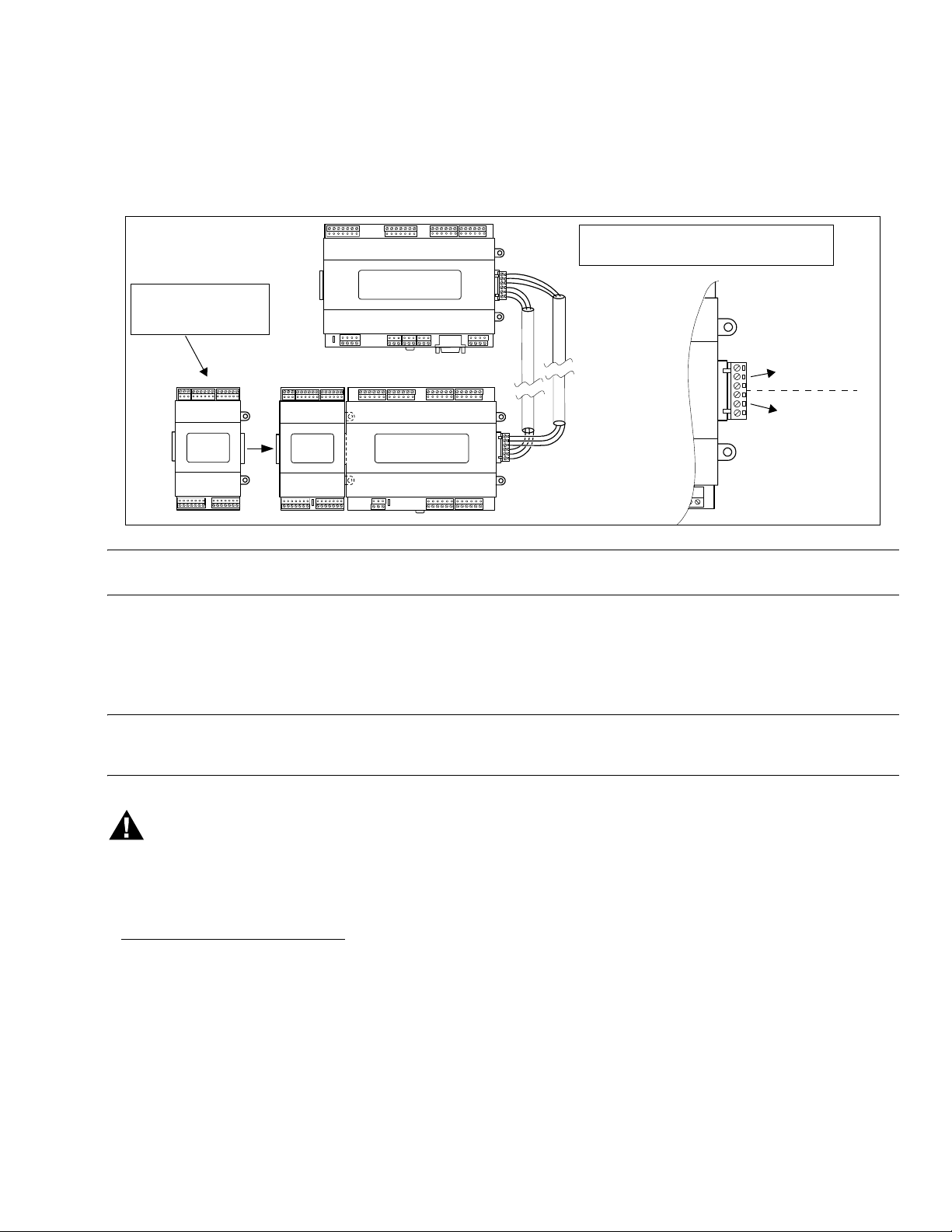
Fig. 1. Expansion modules are Remote 2 Reader (SEC-H-R2R), Remote I/O (SEC-H-RIO).
Expansion modules can
be plugged together into
assemblies
SEC-
H-R2R
SEC-
H-R2R
Security
Controller
SEC-H-RIO
Assemblies are interconnected with RS-485
wiring, and sometimes Power Wiring
.
PS–
PS+
BB
–
+
S
RS-485
DC Power,
Backup Batt.
NOTE: Expansion modules can be plugged into, and removed from, a powered system without causing damage. However, this
is generally not recommended—especially if the system is operational.
Option Cards
The Security Controller has two (2) option slots for on-board mounting of custom option cards. Each slot has a 30-pin connector
on the Security Controller base board (see Fig. 4 on page 12). An option card typically provides additional communication ports.
NOTE: Option cards not evaluated by U.L.
Option card usage in a Security Controller is expected to be infrequent.
WARNING
All power to the Security Controller must be OFF when installing or removing option cards, or damage will occur!
Also, you must be very careful to plug an option card into its connector properly (pins aligned).
Install option cards before performing any other mounting or wiring of the Security Controller.
For installation details, refer to the installation sheet that accompanies the option card.
a
In most cases, backup-battery cabling requires two conductors: PS-, BB. However, if a remote expansion module is mounted in
a Security Enclosure without an integral power supply (SEC-ENC-H-3, SEC-ENC-H-1NP, SEC-ENC-H-2NP), it needs 3-conductor “triad” cabling supplying 15Vdc power and backup battery (PS-, PS+, BB).
3 95-7759—07
SEC-H-600 SECURITY CONTROLLER
WEBs-AX Security Enclosure
For a UL Listed system, the Security Controller, plus all expansion modules, must be mounted in one or more WEBs-AX Security
Enclosures. These enclosures meet the UL 294 listing, have a pre-mounted DIN rail (or rails), and include a door with a key lock
and tamper switch. Two models have an integral 30W 15Vdc power supply that powers the SEC-H-600 controller and/or the
expansion modules inside the enclosure.
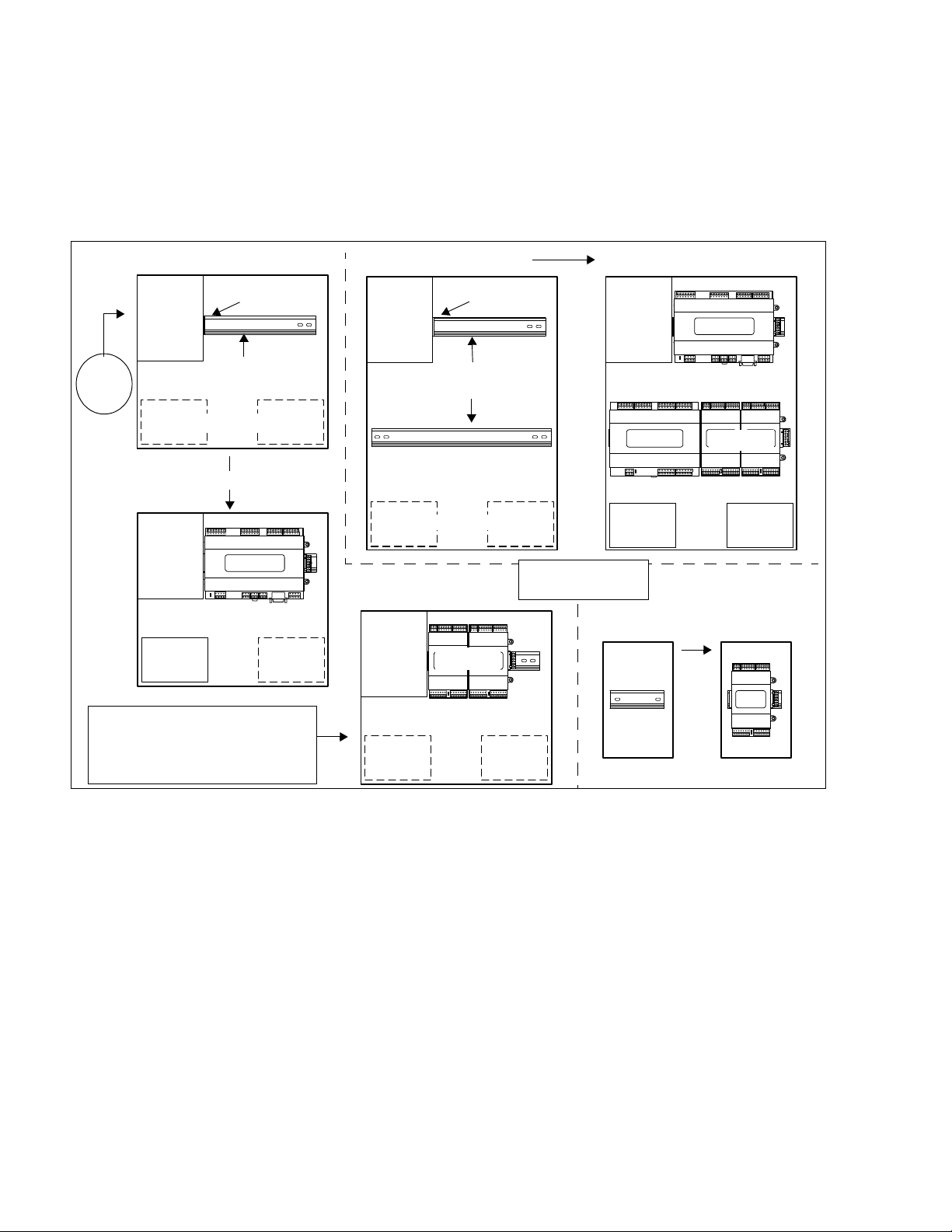
Fig. 2. Security Controller must be mounted in WEBs-AX Security Enclosure (model SEC-ENC-H-1 or SEC-ENC-H-2).
AC Line
Input
120-
240Vac
SEC-ENC-H-1 SEC-ENC-H-2
Integral
30W
15Vdc
PS
Battery Space
Minimal System Configuration
Integral
30W
15Vdc
PS
12V
Backup
Battery
15Vdc
output
35mm DIN Rail
Security
Controller
Battery
Space
Integral
30W
15Vdc
PS
SEC-ENC-H-1
Integral
30W
15Vdc
PS
15Vdc
output
35mm DIN Rails (2)
Battery Space
(2)
SEC-H-R2R
Larger System Configuration
Integral
30W
15Vdc
PS
SEC-H-RIO
12V Backup
Battery
NOTE: Interconnecting
cables not shown.
SEC-ENC-H-3
Security
Controller
(2)
SEC-H-R2R
12V Backup
Battery
Only application
SEC-H-R2R
NOTE: In larger systems, additional
enclosures can be used for modules only
(no Security Controller), where backup
batteries are not used. At right an SEC-
Unused
Space
Unused
Spac e
35mm
DIN Rail
ENC-H-1 is used this way.
As shown in Fig. 2, there are 3 different-sized WEBs-AX Security Enclosures available, including these models:
SEC-ENC-H-1: (Medium) For the Security Controller in the smallest job configuration, or where additional expansion modules
are located remotely (in other Security Enclosures). It provides a single DIN rail and an integral 30W 15Vdc power supply to
power the controller, or up to two SEC-H-R2Rs, or one SEC-H-RIO. The controller (or modules) plug directly into the power
supply, see Fig. 2. Brackets at the bottom of the enclosure secure one or two rechargeable sealed lead-acid backup batteries
(batteries used only if a Security Controller is housed). In larger systems, more Security Enclosures can be used to house
additional expansion modules.
Another medium-sized enclosure without an integral power supply is also available, model SEC-ENC-H-1NP. It is used for
expansion modules only (not the Security Controller), and it has room for one additional SEC-H-R2R module.
SEC-ENC-H-2: (Large) Used for the Security Controller in larger job configurations, it provides a DIN rail mount and an integral
30W 15Vdc power supply for the controller, and a second DIN rail for expansion modules—for example, up to four (4) SEC-HR2R modules. The SEC-H-600 controller plugs directly into the power supply, see Fig. 2. A supplied six-conductor wiring harness
(not shown) provides power and RS-485 communications to expansion modules mounted on the lower DIN rail. Brackets at the
bottom of the enclosure secure one or two rechargeable sealed lead-acid backup batteries (backup batteries used only if
enclosure houses an Security Controller). In larger systems, more Security Enclosures can be used to house additional modules.
Another large-sized enclosure without the integral power supply is also available, model SEC-ENC-H-2NP. It is used for
expansion modules only (not the Security Controller), and it has room for one additional SEC-H-R2R module.
95-7759—07 4

SEC-H-600 SECURITY CONTROLLER
SEC-ENC-H-3: (Small) Has a single DIN rail, and is used only for one SEC-H-R2R module—it has no integral power supply or
backup battery area. See Fig. 2 When wiring back to the Security Controller, you must use a 3-conductor cable for power/battery
backup (PS-, PS+, BB), in addition to RS-485 wiring.
Related Documentation
For more information on mounting and wiring a WEBs-AX Security system, refer to the following documents:
• Remote 2 Reader Module (SEC-H-R2R) Installation Instructions, Form number 95-7749
• Remote I/O Module (SEC-H-RIO) Installation Instructions, Form number 74-4060
• Medium (SEC-ENC-H-1/SEC-ENC-H-1NP) and Large (SEC-ENC-H-2/SEC-ENC-H-2NP) Security Enclosure Install Guide,
Form number 95-7747
• Small (SEC-ENC-H-3) Security Enclosure Install Sheet, part number 95-7748
• Security Controller (SEC-H-201) Installation Instructions, part number 95-7759
For details on software configuration for a fully functioning security system, refer to the following documents:
• WEBs-AX Enterprise Security Guide, Form number 74-4086
SYSTEM PLANNING
The following sections provide information necessary to plan a WEBs-AX Security System using a SEC-H-600 Security
Controller. Because of the flexibility of the system architecture, a number of factors may be in play.
• “Basic Design Rules (SEC-H-600)” on page 5
• “Estimating Power and Battery Requirements” on page 6
• “Voltage Drop Considerations” on page 7 and “Maximum Output Load Considerations” on page 8
Basic Design Rules (SEC-H-600)
1. Only one Security Controller, unless part of an Enterprise Security system. The controller provides access control for 2
doors (one reader per door), plus additional I/O points. See “Onboard Security I/O” on page 2.
2. Per SEC-H-600 controller, a maximum of 15 additional SEC-H-R2R (2 reader) modules and SEC-H-RIO (remote I/O) modules total, in any combination. If needed, all 15 can be SEC-H-R2R modules. See “Expansion Modules” on page 2.
3. For a UL 294 listed system, all equipment above must be installed in one or more WEBs-AX Security Enclosures, with a
model SEC-ENC-H-1 or SEC-ENC-H-2 used to house the SEC-H-600 controller. See “WEBs-AX Security Enclosure” on
page 4.
4. All expansion modules must be connected to the Security Controller on an RS-485 communications trunk, using a daisy
chain topology. Also, each reader must be located within 500 feet of the reader input used. For related details, see “Connection Overview” on page 14.
5. Because readers are powered by the Security Controller and any SEC-H-R2R modules, system power requirements vary
depending on the exact reader models used. Identify the power used/amps drawn by readers.
6. The Security Controller requires 15Vdc primary power—typically, this is supplied by the integral power supply of the
required SEC-ENC-H-1 or SEC-ENC-H-2 model enclosure. Note that 15Vdc is required so that the Security Controller can
keep its attached 12V backup battery(ies) trickle charged.
7. Expansion modules can be powered from 12–15Vdc—modules directly attached (in same enclosure) with the Security
Controller use the enclosure’s 15Vdc source and backup battery. On larger jobs, when installing additional SEC-ENC-H-1
or SEC-ENC-H-2 enclosures to house (remote) expansion modules, expansion modules are powered by the local (enclosure) power supply, where you can wire the backup battery supply from the enclosure with the Security Controller (at a
maximum of 2.5A load). This method uses a single pair (2 twisted conductor) cable to connect terminals “PS-, “BB”.
If installing a non-powered enclosure (SEC-ENC-H-1NP, SEC-ENC-H-2NP, SEC-ENC-H-3) to house one or more expansion modules, you can either:
• Wire a “triad” (3 twisted conductor) cable back to the Security Controller enclosure, for both 15Vdc power and battery
backup (terminals “PS+, “PS-, “BB”).
• Use a UL 294 approved, third-party, battery-backed, 12Vdc power supply to locally power the remote expansion
modules. See the expansion module installation documents for more details.
8. When the system is operating on backup battery (AC power lost scenario), system operation for a minimum of 4 hours is
the intended goal. To achieve this, size the Backup Battery(ies) accordingly, using the section Estimating Power and Battery Requirements below.
5 95-7759—07
SEC-H-600 SECURITY CONTROLLER
Estimating Power and Battery Requirements
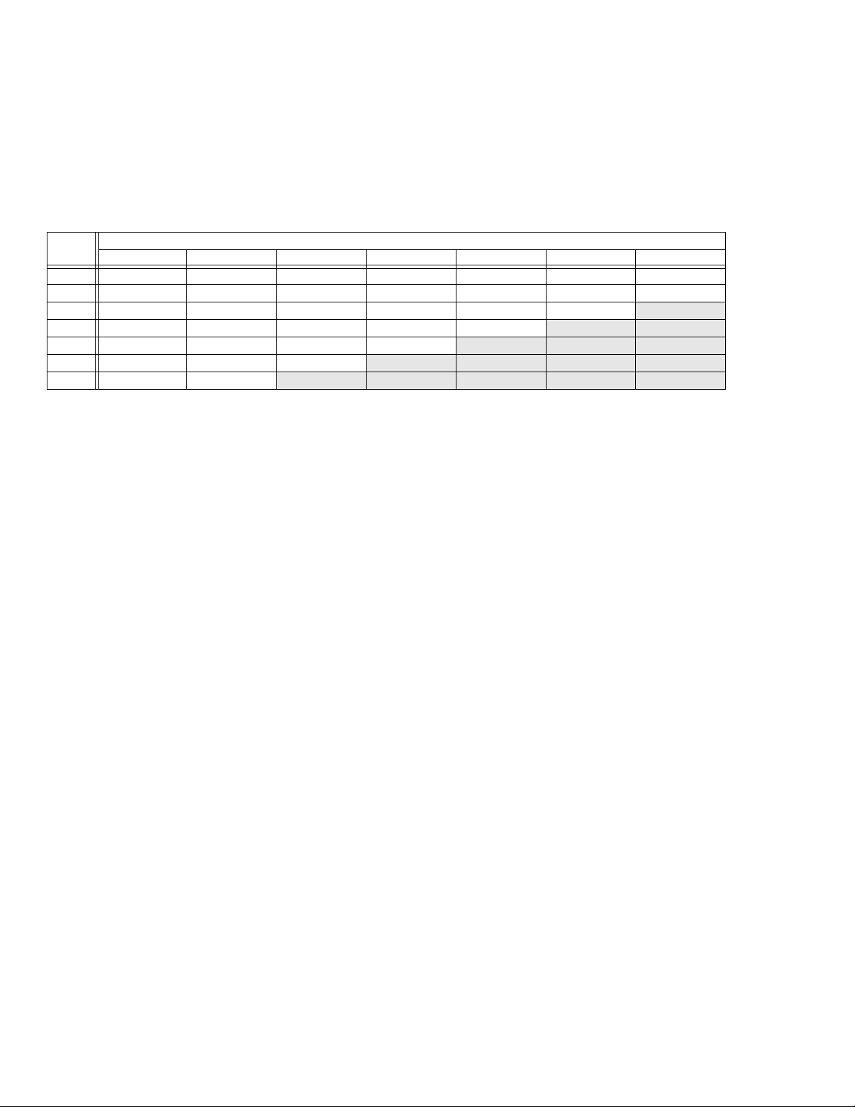
Table 2 provides example “worst case” power consumptions and minimum recommended Backup Battery capacity needed in a
WEBs-AX Security system, by the Security Controller and possible expansion modules.
NOTE: The Security Controller, as well as SEC-H-R2R modules, supply power to connected Wiegand-type readers. Depending
on the exact reader type and manufacturer, the power used will vary. Examples here use two reader models: one that
draws 0.13A maximum, and another that draws 0.04A maximum. For best estimates, refer to the amp usage specifications of the readers that you will be using.
Maximum current ratings for reader-capable devices (Security Controller and SEC-H-R2R) are as follows:
Maximum peak current for both readers combined is 0.40A.
Maximum average current for both readers combined is 0.30A.
Estimates assume all on-board relays of devices are energized—not typically found in an actual application, but necessary for worst-case power usage calculations.
Door strike power is not included, nor is power for other loads switched by the Security Controller and its expansion
modules. Door strikes and other loads should be always be powered by other sources.
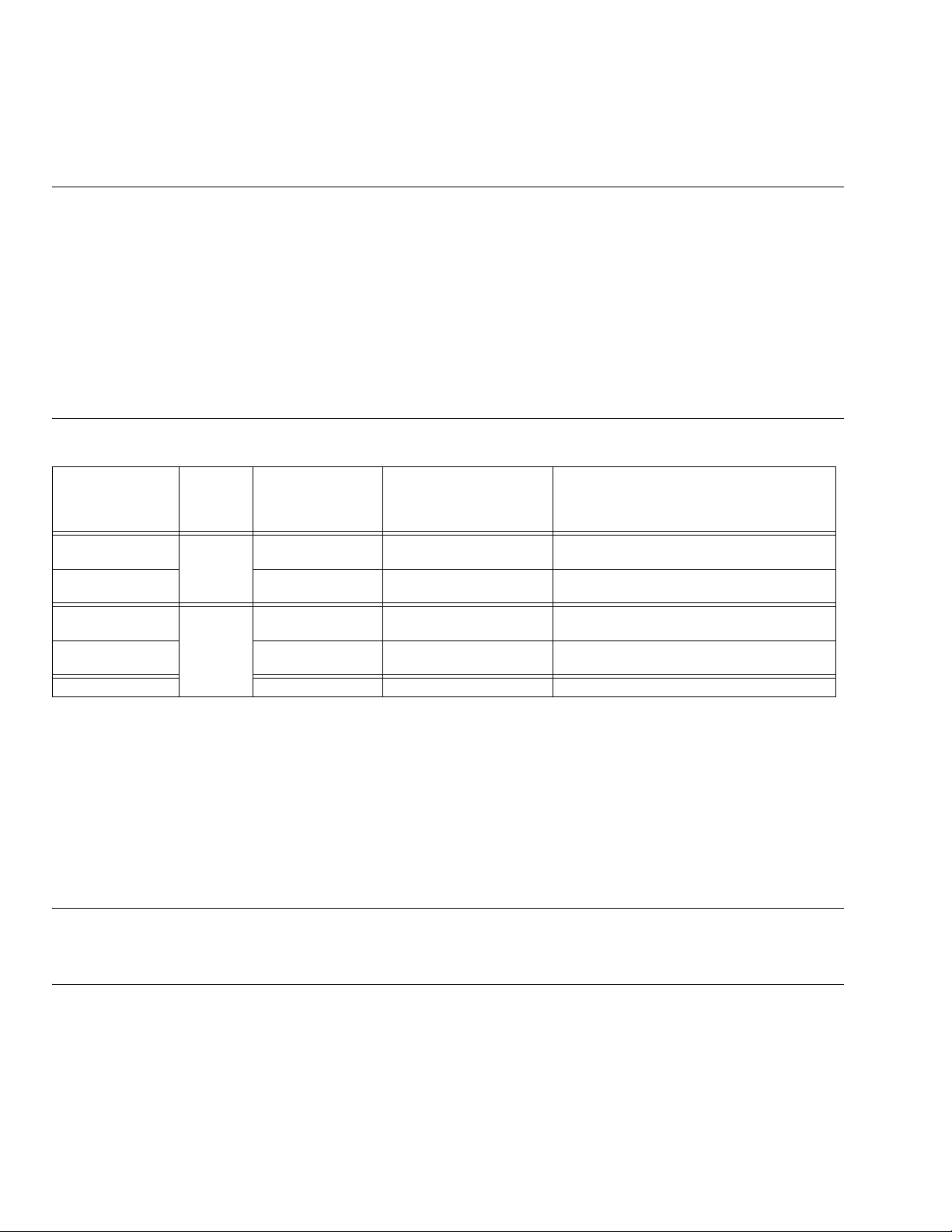
Table 2. Amps/Watts, Recommended Minimum 12V SLA battery A-Hr capacities, for SEC-H-600 and modules.
12V Backup Battery
(4 hours)
Max per
Device
SEC-H-600
(0.13A readers)
SEC-H-600
(0.04A readers)
SEC-H-R2R
(0.13A readers)
SEC-H-R2R
(0.04A readers)
SEC-H-RIO 0.40A / 6.0W 2.00 Ah No reader inputs, but has 8 on-board relays.
System
1 0.67A / 10.0W 3.33 Ah SEC-H-600 powers two readers, measured
15
in
aggregate
Amps / W used
@ 15Vdc (each)
0.48A / 7.2W 2.40 Ah SEC-H-600 powers two readers, measured
0.33A / 5.0W 1.67 Ah SEC-H-R2R powers two readers, measured
0.11A / 1.7W 0.56 Ah SEC-H-R2R powers two readers, measured
min. recommended Ah
(each) Notes
drawing 0.13A each.
drawing 0.04A each.
drawing 0.13A each.
drawing 0.04A each.
Note that minimum Ah (Amp hour) figures for the backup battery were calculated using “80% capacity” (1.25 multiplier) due to
either charge level or age. For example, each SEC-H-RIO (with all 8 relays energized) draws about 0.4A (6.0W at 15Vdc). When
powered by the 12V backup battery, Ah is calculated as follows:
0.4A x 4 hours = 1.60Ah x 1.25 = 2.0Ah
To calculate the system (total) DC power supply requirements and minimum SLA backup battery capacity, add up the total watts
(W) and minimum Amp hours (Ah), for all devices. Where n is number of modules:
• Min. power supply (W) = SEC-H-600 W + (n x SEC-H-R2R W) + (n x SEC-H-RIO W) = total W
• Min. backup battery (Ah) = SEC-H-600 Ah + (n x SEC-H-R2R Ah) + (n x SEC-H-RIO Ah) = total Ah
NOTE: Backup battery(ies) are often sized greater than the recommended minimum, for additional reserve.
A maximum 2.5A load is supported at the SEC-H-600 controller’s output terminals (PS-, PS+, BB), above which an
onboard fuse may blow. See “Maximum Output Load Considerations” on page 8.
95-7759—07 6

SEC-H-600 SECURITY CONTROLLER
Power Estimate Examples
Two example estimates are provided here, as follows:
• System 1, 8 door readers
• System 2, 10 door readers
SYSTEM 1, 8 DOOR READERS
This system requires 8 door readers and additional IO points requiring one SEC-H-RIO module. Two readers attach to the
Security Controller, the other 6 readers require 3 SEC-H-R2R modules (2 readers each). All readers draw 0.04A maximum, such
that power/battery calculations (Table 2) factor this in.
• Min. power supply (W) = 7.2W + (3 x 1.7W) + (1 x 6.0W) = 7.2W + 5.1W + 6.0W = 18.3W
• Min. backup battery (Ah) = 2.40Ah + (3 x 0.56Ah) + (1 x 2.0Ah) = 2.4Ah + 1.68Ah + 2.0Ah = 6.08Ah
In this case, a single 30W Enclosure Power Supply provides ample reserve, and the equipment could be housed in two
enclosures as follows:
• SEC-ENC-H-2 (large): SEC-H-600 controller, one SEC-H-RIO module, two SEC-H-R2R modules.
• SEC-ENC-H-3 (small): one SEC-H-R2R module.
The sealed lead acid Backup Battery in this case might be two 12V 7.0Ah types in parallel, providing 14.0Ah total. Between the
two Security Enclosures, module assemblies are wired together using 3-conductors for power/backup battery (“PS-”, “PS+”,
“BB”).
SYSTEM 2, 10 DOOR READERS
The system requires 10 door readers and additional IO points requiring two SEC-H-RIO modules. Two readers attach to the
Security Controller, the other 8 readers require 4 SEC-H-R2R modules (2 readers each). Readers draw 0.13A maximum, such
that power/battery calculations (Table 2) factor this in.
• Total min. power supply (W) = 10.0W + (4 x 5.0W) + (2 x 6.0W) = 10.0W + 25.0W + 12.0W = 42.0W
• Min. backup battery (Ah) = 3.33Ah + (4 x 1.67Ah) + (2 x 2.0Ah) = 3.33Ah + 6.68Ah + 4.0Ah = 14.01Ah
Assuming that all equipment is located relatively nearby, it could be housed in two large enclosures, with each enclosure’s 30W
power supply providing ample 15Vdc power to equipment inside, as follows:
• SEC-ENC-H-2 A (large): SEC-H-600 controller, one SEC-H-RIO module, two SEC-H-R2R modules (26W).
• SEC-ENC-H-2 B (large): One SEC-H-RIO, two SEC-H-R2R (16W).
Between Security Enclosures, module assemblies are wired together using 2-conductors for battery backup, that is “PS-” and
“BB”. In this case, the sealed lead acid Backup Battery in this case might be two 12V 12.0Ah types in parallel, providing 24.0Ah
total.
NOTE: If the SEC-H-R2R and/or SEC-H-RIO expansion modules are mounted in remote locations from the Security Controller
and its backup batteries, or if a large system with multiple local power supplies, additional factors apply. See the next
sections “Voltage Drop Considerations” and “Maximum Output Load Considerations.”
Voltage Drop Considerations
When using an Enclosure Power Supply and backup battery to power the Security Controller plus all expansion modules, and
some modules are not mounted in the same enclosure with the SEC-H-600, you must be aware of voltage drops in the
connecting “trunk power” cabling. Typically, this applies only if modules are located in different locations—that is, not in the same
enclosure or in adjacent enclosures.
NOTE: The 15Vdc power supply and the backup battery(ies) charged by the Security Controller must always be located in the
same Security Enclosure as the Security Controller.
Undersized selection of cabling can result in unacceptably high voltage drops, and expansion modules/attached readers may not
operate correctly—especially during emergency (battery backup) operation.
7 95-7759—07
SEC-H-600 SECURITY CONTROLLER
The maximum allowable voltage drop due to wiring is 1.5V. This equates to the difference in voltage measured across the
PS+ and PS- at the source SEC-ENC-H-1 or SEC-ENC-H-2 enclosure power supply, and the PS+ and PS- at the furthest nonpowered Security Enclosure that houses an expansion module. Or, when powered by battery backup, the difference in voltage
measured across the BB and PS- at the enclosure with the Security Controller, and the BB and PS- at the furthest WEBs-AX
Security Enclosure.
Table 3 provides a voltage drop chart, showing voltage drops per 100 feet of paired wire of different gauges (AWG), at different
load amps. Also see “Connection Overview” on page 14.
Table 3. Voltage Drop Per 100 Feet Run (30m) of Paired Wire.
Gauge
(AWG)
10 0.0200.050.100.200.300.400.80
12 0.0320.080.160.320.480.641.27
14 0.0500.130.250.500.751.01
16 0.080 0.20 0.40 0.80 1.20
18 0.127 0.32 0.64 1.27
20 0.202 0.50 1.01
22 0.320 0.80
See Table 2 for “worst case” amps used by SEC-H-R2R and SEC-H-RIO modules, using two different reader types (readers draw
either 0.13A or 0.04A each).
For an example, consider in the previous System 2, 10 door readers, that two of the four SEC-H-R2R modules are mounted
remotely in locations 500 feet (366m) away. In this example, worst-case amps used by each remote SEC-H-R2R is 0.33A.
Looking at Table 3 at the 0.25A column, a #16 AWG cable pair drops 0.20V per 100 feet, meaning a 500 foot run would drop
slightly over 1V—this would be a good choice over an #18 AWG cable, which would drop over 2V (above the 1.5V maximum
allowable drop).
0.10A 0.25A 0.5A 1.0A 1.5A 2.0A 4.0A
1.60 3.20 4.80 6.40 12.81
Load Current
2.02
1.60 3.20
1.91 2.54 5.08
2.02 3.03 4.03 8.07
Maximum Output Load Considerations
If using multiple powered Security Enclosures (SEC-ENC-H-1, SEC-ENC-H-2) to power a large system, and running only battery
backup power from the SEC-H-600 controller (on terminals PS-, BB of the SEC-H-201) to expansion modules in other
enclosures, be aware that the output load cannot exceed 2.5A.
If the output load exceeds this, a soldered (unreplaceable) 2.5A fuse on the SEC-H-600 controller can blow.
Therefore, large systems that are dependent on battery backup operation may need to have remote expansion modules mounted
in unpowered Security Enclosures, where they are powered locally using approved third-party, battery-backed 12Vdc power
supplies. See the “UL Requirements” section “Battery-backed Power Supplies,” page 29, for a listing of approved power supply
models. Related wiring details are in the installation document for expansion modules; see “Related Documentation,” page 5.
PREPARATION
Unpack the Security Controller and inspect the contents of the package for damaged or missing components. If damaged, notify
the appropriate carrier at once and return any damaged components for immediate repair or replacement. See “Returning a
Defective Unit,” page 35. See the following sections below: “Included in this Package” and “Material and Tools Required.”
Included in this Package
Included in this package you should find the following items:
• A Security Controller base controller (SEC-H-600).
• This document, Security Controller (SEC-H-600) Mounting & Wiring Guide, Form number: 95-7759.
• A hardware bag containing the following items:
— Nine (9) pin-mount, screw-terminal connectors (two 7-position, two 6-position, two 4-position, three 3-position) for con-
nection of security I/O points, sealed lead-acid backup battery. For more details, see “About Screw Terminal Connectors,”
page 12.
— One (1) grounding wire, with quick-disconnect 0.187" female connector.
— 6 end-of-line resistor packs (four leads each) for installation at contacts wired to supervised inputs.
— One (1) 6-position screw terminal end-plug, for optional wiring of power, battery, and RS-485 communications to another
chain of modules (not mounted in-line with the SEC-H-600 controller).
95-7759—07 8

SEC-H-600 SECURITY CONTROLLER
Material and Tools Required
The following supplies and tools are required for installation:
• Medium or large sized WEBs-AX Security Enclosure, model SEC-ENC-H-1 or SEC-ENC-H-2. See “WEBs-AX Security
Enclosure,” page 4, for more details.
• Suitable tools and supplies for mounting enclosure, SEC-H-600 model of Security Controller and expansion modules, and for
making all wiring terminations.
PRECAUTIONS
This document uses the following warning and caution conventions:
CAUTION
Cautions remind the reader to be careful. They alert readers to situations where there is a chance that the reader
might perform an action that cannot be undone, might receive unexpected results, or might lose data. Cautions
contain an explanation of why the action is potentially problematic.
WARNING
Warnings alert the reader to proceed with extreme care. They alert readers to situations where there is a chance
that the reader might do something that can result in personal injury or equipment damage. Warnings contain an
explanation of why the action is potentially dangerous.
Safety Precautions
The following items are warnings of a general nature relating to the installation and start-up of the Security Controller. Be sure to
heed these warnings to prevent personal injury or equipment damage.
WARNING
The circuit powering the controller is from 120 to 240Vac at 50/60 Hz. Disconnect power before installation or
servicing to prevent electrical shock or equipment damage.
Make all connections in accordance with national and local electrical codes. Use copper conductors only.
To reduce the risk of fire or electrical shock, install in a controlled environment relatively free of contaminants.
This device is only intended for use as a monitoring and control device. To prevent data loss or equipment
damage, do not use it for any other purpose.
Static Discharge Precautions
Static charges produce voltages high enough to damage electronic components. The microprocessors and associated circuitry
within a Security Controller are sensitive to static discharge. Follow these precautions when installing, servicing, or operating the
system:
CAUTION
Work in a static-free area.
Discharge any static electricity you may have accumulated. Discharge static electricity by touching a known,
securely grounded object.
Do not handle the printed circuit board (PCB) without proper protection against static discharge. Use a wrist
strap when handling PCBs. The wrist strap clamp must be secured to earth ground.
9 95-7759—07

SEC-H-600 SECURITY CONTROLLER
MOUNTING
Mount the SEC-H-600 controller in a WEBs-AX Security Enclosure (model SEC-ENC-H-1 or SEC-ENC-H-2). This enclosure
meets the UL 294 Listing, has an integral 30W power supply, either one or two pre-mounted DIN rails, a door with a key lock and
tamper switch, and brackets to secure backup batteries.
NOTE: All U.S. Installations: For a UL Listed system (UL 294) you must mount the Security Controller (SEC-H-600) in a
“WEBs-AX Security Enclosure,” page 4. All expansion modules must also be mounted in a WEBs-AX Security Enclosure, either the same enclosure or in additional enclosures. If the Security Controller and/or expansion modules are
removed and installed in any other enclosure (even one with the same listings), both UL listings are voided! Also refer to
“UL Requirements,” page 28.
The following general mounting information applies to a SEC-H-600 controller:
• Environmental Requirements
• Physical Mounting
Environmental Requirements
Note the following requirements for the Security Controller mounting location:
• This product is intended for indoor use only. Do not expose the unit to ambient conditions outside of the range of 2ºC (35º F) to
50ºC (122º F) and relative humidity outside the range 5% to 95% non-condensing (pollution degree 1).
• The WEBs-AX Security Enclosure is designed to keep the unit within its required operating range considering a 20-watt
dissipation by the controller.
• Do not mount the unit:
— in an area where excessive moisture, corrosive fumes, or explosive vapors are present.
— where vibration or shock is likely to occur.
— in a location subject to electrical noise. This includes the proximity of large electrical contractors, electrical machinery,
welding equipment, and spark igniters.
Physical Mounting
The following information applies about physically mounting the unit.
• Before mounting the Security Controller, install Option Cards, (if any) in the unit. See “Removing and Replacing the Cover,”
page 11. Refer also to the installation sheet that came with the option card.
• Mount inside a WEBs-AX Security Enclosure (see previous Note), onto the top 35mm wide DIN rail. Plug the Security
Controller directly into the integral power supply.
• It it not necessary to remove the cover before mounting.
The following procedure provides step-by-step DIN rail mounting instructions for the SEC-H-600 (see Fig. 3).
1. Position the Security Controller on the top DIN rail, tilting to hook DIN rail tabs over one edge of the DIN rail.
2. Use a screwdriver to pry down the plastic locking clip, and push down and in on the Security Controller, to force the locking
clip to snap over the other edge of the DIN rail.
3. Slide the Security Controller along the DIN rail to connect its 6-position plug into power supply socket.
On the right side of the controller, holes in the two plastic mounting tabs should be aligned with the tapped holes in the back
of the enclosure.
4. Install supplied screws through the mounting tab holes into the enclosure holes, and tighten.
If a medium-sized
5. If a large SEC-ENC-H-2 enclosure, clip all expansion modules onto the lower DIN rail in the same way, but do not secure
yet.
6. Slide the left-most module to the far left, such that its locking-tab holes align with tapped holes in the enclosure, and secure
with two supplied screws.
7. Slide the next expansion module into the left (secured) module, connecting the 6-position connectors between them firmly
together, and secure with two supplied screws into its mounting tabs.
8. Repeat this for all items, until all are mounted on the lower DIN rail, firmly connected to each other, and secured with
mounting tab screws. Connect the 6-wire plug harness between the Security Controller and the assembly of expansion
modules on the lower DIN rail.
SEC-ENC-H-1 enclosure, this is the last mounting step.
95-7759—07 10
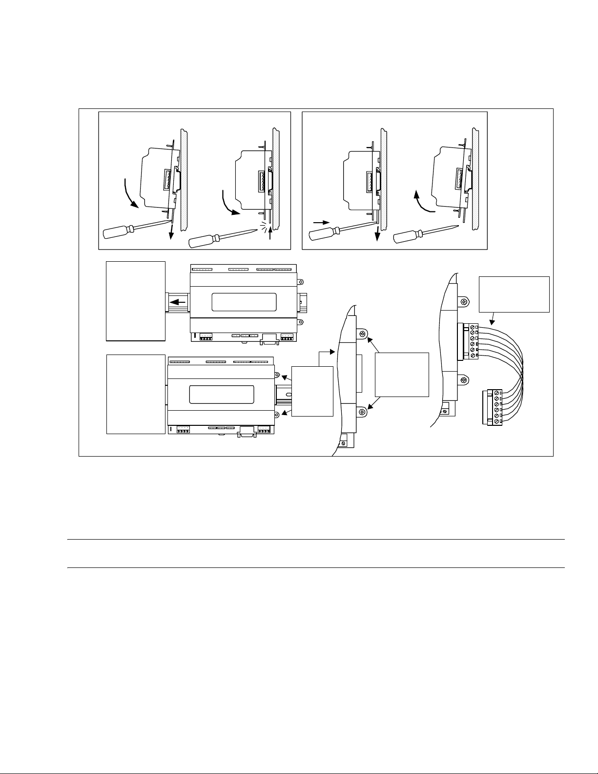
Fig. 3. Security Controller mounting details.
SEC-H-600 SECURITY CONTROLLER
Mounting on DIN Rail
SEC-ENC-H-1
or
SEC-ENC-H-2
Enclosure
Power Supply
Security
Controller
Security
Controller
Tab holes
align with
tapped
holes in
enclosure.
Removing from DIN Rail
Install supplied
phillips head
screws in
mounting tabs
(2) and tighten.
SEC-ENC-H-2
enclosure includes
wiring harness for
expansion modules.
Removing and Replacing the Cover
You must remove the Security Controller cover to connect the NiMH battery (new unit), or to replace this battery, or to install any
option boards. The cover snaps onto the base with four plastic tabs (two on each end).
To remove the cover, press in the four tabs on both ends of the unit, and lift the cover off.
NOTE: If expansion modules are plugged into the Security Controller, you may need to slide them away from the unit to get to
the cover tabs.
To replace the cover, orient it so the cutout area for comm ports is correct, then push inwards to snap in place.
11 95-7759—07
 Loading...