

Page 1
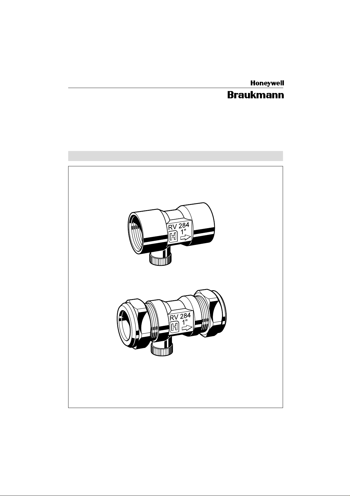
RV 284
Einbau-Anleitung . Installation Instructions
Instructions de montage
EB-RV284 2301500
Rückflußverhinderer
Non Return V alve
Page 2
1.
231
4
6
8
2
bar
0
10
2.
4
5.
RV 284
①
②
Page 3

Inhaltsübersicht Seite
D
1. Einbau 2
2. Instandhaltung 2
3. Verwendungsbereich 2
4. Sicherheitshinweise 2
5. Ersatzteile 2
Index Page
GB
1. Installation 3
2. Inspection and maintenance 3
3. Range of application 3
4. Safety guidelines 3
5. Replacement parts 3
Index Page
F
1. Installation 3
2. Maintenance 3
3. Domaine d'application 3
4. Conseils de sécurité 3
5. Pièces de rechange 3
Page 4

D
1. Einbau
Beim Einbau sind die örtlichen Vorschriften,
sowie allgemeine Richtlinien und die Einbau-Anleitung zu beachten. Der Einbauort
muß frostsicher und gut zugänglich sein.
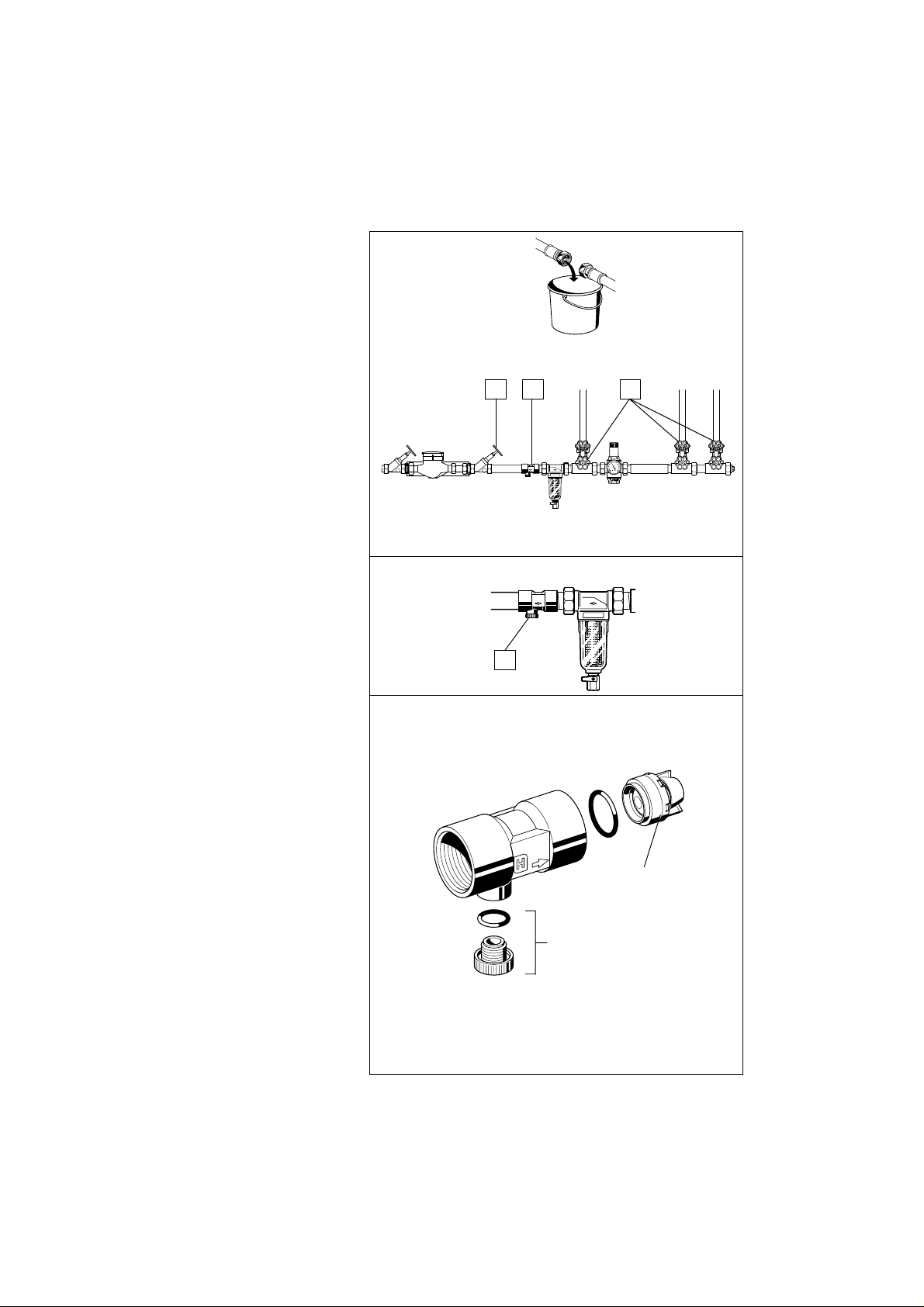
1.1 Montage
1. Rohrleitung gut durchspülen.
2. Ventile 1 und 2 schließen.
3. Rückflußverhinderer 3 einbauen
● Einbaulage in waagrechte oder in Fließ-
richtung nach oben führende Rohrleitung
● Prüfstopfen nach unten.
4. Ventile 1 und 2 langsam öffnen.
2. Instandhaltung
☞ Wir empfehlen dem Betreiber, einen
Wartungsvertrag mit einem Instal-
lationsunternehmen abzuschließen.
Entsprechend der DIN 1988, Teil 8 sind
folgende Maßnahmen regelmäßig durchzuführen:
Der Rückflußverhinderer muß jährlich
überprüft werden. Diese Überprüfung darf
vom Betreiber durchgeführt werden.
1. Absperrventil 1 schließen.
2. Prüfstopfen 4 öffnen.
Bis zur Druckentlastung wird etwas
Wasser am Prüfstopfen ausfließen.
Nach kurzer Zeit muß der Wasserausfluß aufhören. Tropft oder läuft das
Wasser beständig weiter, so ist der
Rückfluß verhinderer beschädigt oder
verschmutzt. Wenden Sie sich zur
Fehlerbeseitigung an Ihren Installateur.
3. Prüfstopfen 4 wieder schließen.
4. Absperrventil 1 wieder öffnen.
3. Verwendungsber eich
Anschlußgrößen A = mit Innengewinde
Betriebsdruck max. 16 bar
Betriebstemperatur Wasser bis 75 °C
1
R
/2" - R 1"
B = mit Klemmringver-
schraubung Æ15,
Æ22 und Æ28
(kurzzeitig bis 90 °C)
4. Sicherheitshinweise
1.Benutzen Sie das Gerät
● in einwandfreiem Zustand
● bestimmungsgemäß
● sicherheits- und gefahrenbewußt.
2. Beachten Sie die Einbau-Anleitung.
3. Lassen Sie Störungen, welche die
Sicherheit beeinträchtigen können,
umgehend beseitigen.
4. Der Rückflußverhinderer RV 284 ist
ausschließlich für die in dieser EinbauAnleitung genannten Einsatzgebiete
bestimmt. Eine andere oder darüber
hinaus-gehende Benutzung gilt als
nicht bestimmungsgemäß.
5. Ersatzteile
① Einsteckrückfluß-
verhinderer
② Sechskantstopfen1/2"-1" S 06 K - 1/4
1
/2" 2166200
3
/4" 2110200
1" 2164400
2
Page 5

1. Installation1. Installation
1. Installation
1. Installation1. Installation
It is necessary during installation to
observe codes of good practice, to comply
with local requirements and to follow the
installation instructions. The installation
location should be protected against frost
and be easily accessible.
1.1 Assembly1.1 Assembly
1.1 Assembly
1.1 Assembly1.1 Assembly
1. Flush pipework thoroughly.
2. Close valves 1 and 2 .
3. Install the non return valve 3 .
● Install in horizontal or with flow
direction pointing upwards in vertical
pipework
● Test valve pointing downwards
4. Slowly open valves 1 and 2 .
2. Maintenance
Planned maintenance is recommended
and DIN 1988, Part 8 specifies the
following operations:
The check valve must be tested once a
year. This can be done by the user.
1. Close shutoff valve 1 .
2. Open the test valve 4 .
Until the pressure has been relieved, a
little water will emit from the test valve.
Emission of water should stop after a
few moments. If water continues to drip
or run without stopping, then the check
valve is either damaged or dirty. This
should be corrected by a specialist.
3. Close test valve 4 .
4. Open shutoff valve 1 .
GB
3. Scope of Application
Connection sizes A = internal thread
connection R ½” to R 2"
B = with compression
ring fitting Æ15, Æ22
and Æ28
Operating
pressure maximum 16 bar
Operating
temperature water up to 75 °C
(for short period up to 90 °C)
4. Safety Guidelines
1. Use the appliance
● In good condition
● According to regulations
● With due regard to safety
2. Follow installation instructions
3. Immediately rectify any malfunctions
which may influence safety.
4. RV 284 non return valve is exclusively
for use in applications detailed in these
installation instructions.
Any variation from this or other use will
not comply with requirements.
5. Spare Parts
① Check valve
insert
② Hexagon blanking1/2"-1" S 06 K - 1/4
plug
1
/2" 2166200
3
/4" 2110200
1" 2164400
3
Page 6

1. Installation1. Installation
1. Installation
1. Installation1. Installation
Lors du montage il faudra observer la
réglementation locale ainsi que les
directives générales et les instructions de
montage. Le lieu d’installation sera à l’abri
du gel et bien accessible.
1.1 Montage
1. Bien rincer la tuyauterie.
2. Fermer les vannes 1 et 2 .
3. Monter le clapet antiretour
● Position de montage dans un tuyau
horizontal ou ascendant dans le sens
du courant
● Robinet de contrôle dirigé vers le bas
4. Ouvrir les vannes 1 et 2 .
2. Maintenance
☞ Nous conseillons à l’utilisateur de
conclure un contrat d’entretien avec
un installateur.
D’après DIN 1988, partie 8, les mesures
suivantes sont à prendre régulièrement:
Le clapet antiretour sera vérifié tous les
ans. L’utilisateur pourra s’en charger
1. Fermer la vanne d’arrêt 1 .
2. Ouvrir le robinet de contrôle 4 .
Jusqu’au moment de la dépressurisation
un petit peu d’eau s’écoulera du robinet
de contrôle. Après quelque temps cet
écoulement doit s’arrêter. Si l’eau continue
à couler sans arrêt, cela signifie que le
clapet antiretour est abîmé ou bien
encrassé. Adressez-vous alors à votre
installateur pour éliminer le défaut.
3. Refermer le robinet de contrôle 4 .
4. Rouvrir la vanne d’arrêt 1 .
F
3. Domaine d’application
Diamètre de
raccordement A = avec filetage intérieur
1
R
/2" - R 1"
B = avec écrou de
blocage à chape
Æ15, Æ22 et Æ28
Pression de
service max. 16 bar
Témperature
de service Eau jusqu’à 75°C max.
(Un bref instant jusqu'a 90 °C
4. Conseils de sécurité
1. Utiliser le dispositif
● en parfait état de marche
● conformément à son but
● en tenant compte de la sécurité et de
dangers éventuels.
2. Respecter les instructions de montage.
3.Faire éliminer immédiatement toute
panne pouvant compromettre la
sécurité.
4.Le clapet antiretour RV 284 est
uniquement destiné aux domaines
d’application dont question dans ces
instructions de montage. Toute autre
utilisation en dehors de ces domaines
est à considérer comme contraire à son
but.
5. Pièces de rechange
① Clapet antiretour
insérable
② Purgeur hexagonal1/2"-1" S 06 K - 1/4
1
/2" 2166200
3
/4" 2110200
1" 2164400
)
Braukmann Armaturen
Honeywell AG
Hardhofweg . D-74821 Mosbach
11/97
 Loading...