

Page 1
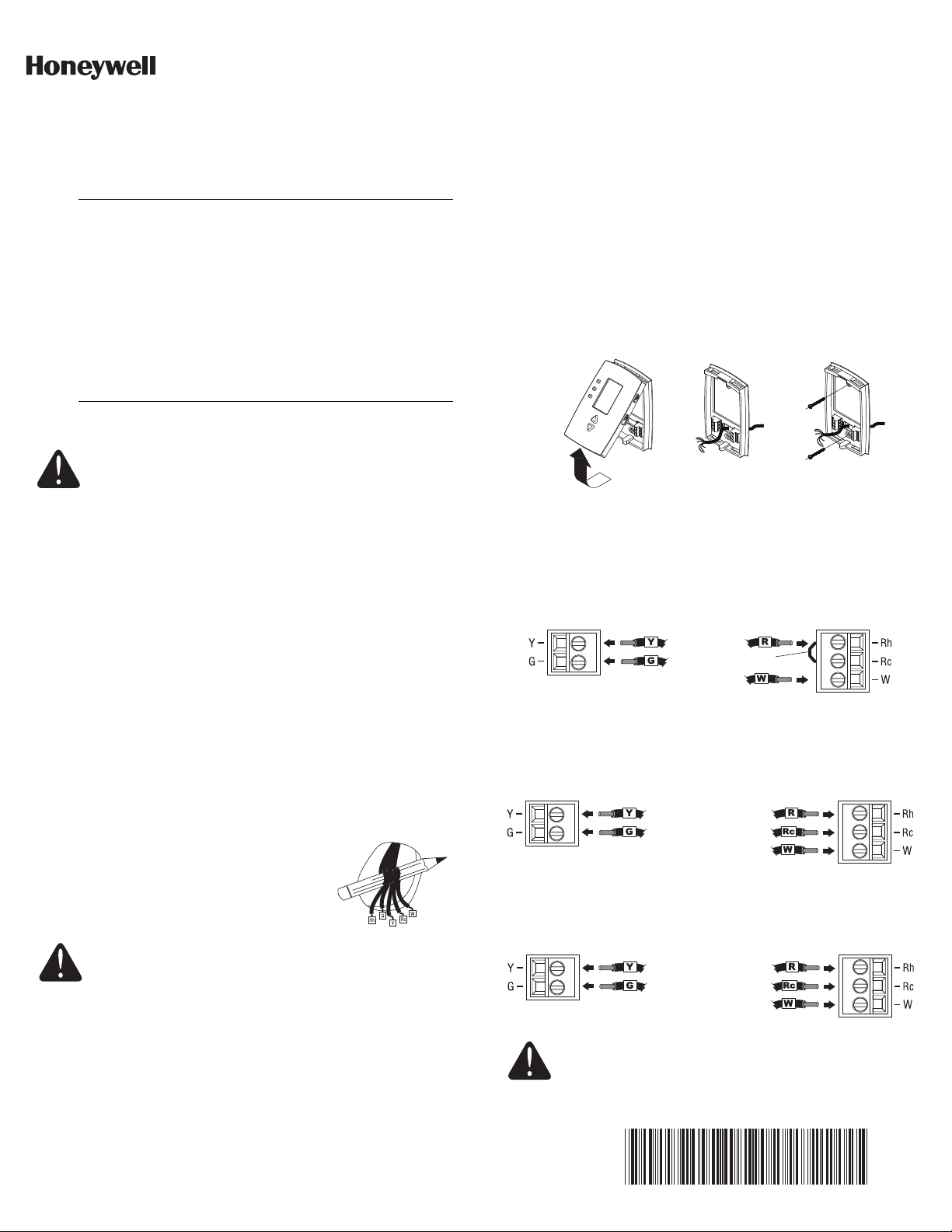
Figure 1
Figure 2
Figure 3
Jumper
Rh, 4 or V
R
W1 or H
Y1 or M
F
RTH111/RTH221
Installation Guide
Programmable and Non-programmable Thermostats
The RTH111/RTH221 thermostats can be used to control:
• a gas, oil or electric furnace — 2 or 3 wires
• a central air conditioner — 2 or 3 wires
• a hot water system (steam or gravity) with or without pump — 2 wires
• a millivolt system — 2 wires
• a central heating system with air conditioning — 4 or 5 wires
NOTE: This thermostat is not compatible with heat pumps or
multi-stage systems.
Introduction
Installation
CAUTION: ELECTRICAL HAZARD
Can cause electric shock or equipment damage.
Disconnect power before beginning installation.
2.1 Removing the old thermostat
IN ORDER TO AVOID ANY RISK OF ELECTRIC SHOCK, CUT
POWER TO THE HEATING SYSTEM.
Remove the old thermostat to access the wires.
WARNING: If the old thermostat was mounted onto an electrical
box, it might have been powered by 120/240 volts. In this case,
this thermostat cannot be used. If you are unsure of the voltage
supplied to your thermostat, contact an electrician.
Identify and label each wire (with the corresponding letter on the
thermostat terminal) and remove it from the terminal.
NOTE 1: Ignore wire colors, use only letter designations to
identify wire types.
NOTE 2: If any wires are not attached to the terminals of your old
thermostat, you do not need to label them as they will not be
connected to your new thermostat.
If necessary, strip the end of each wire (maximum of 1/4 inch).
Wrap the loose wires around a pencil to
prevent them from falling into the wall.
If the hole in the wall is too big, insulate it
using a non-flammable material to avoid air
draughts behind the thermostat.
MERCURY NOTICE
If this product is replacing a control that contains mercury
in a sealed tube, do not place the old control in the trash.
Contact your local waste management authority for
instructions regarding recycling and proper disposal.
1.
NOTE: Levelling is for esthetics only and will not affect the
performance of the thermostat.
Drill holes at the marked positions and insert supplied wall
anchors.
Pass the wires through the large opening at the bottom center of
the wallplate as per Figure 2.
Secure the wallplate to the wall with supplied mounting screws
as per Figure 3.
2.
2.3 Wiring
It is important that you match the wire labels with the corresponding
terminals on the thermostat.
NOTE: Depending on your system, you might not need to connect to
all terminals.
Remove the jumper wire between Rh and Rc terminals if you have
both Rh and Rc wires as shown in the following illustration.
If a wire label does not match a terminal designation on the thermostat, refer to the following illustration to find the corresponding alternate wire label.
2.2 Wallplate installation
Loosen the locking screw at the bottom of the thermostat. Note
the screw is captive and cannot be removed from the wallplate.
Do not connect wires identified as C, C1, X or B as these
wires are not used with this thermostat. Wrap the bare
end of these wires with electrical tape, so they cannot
touch and short out other wires.
Separate the thermostat from the wallplate as per Figure 1.
Position the wallplate against the wall and mark hole positions
with a pencil.
RT H111/ RTH 221 1/8
69-2060EFS-02
Page 2
2.4 Fan operation setting
Function
number
Option
number
NOTE: This setting is not applicable if there is no fan connected to
the G terminal.
The jumper is located on the back of the thermostat faceplate. It
determines how the fan operates when placed in Automatic mode.
• HG (factory setting): Leave the jumper in this position for gas or oil
heating systems. In this position, the heating system controls the
fan operation and activates the fan only when the plenum air is
sufficiently warm.
• HE: Place the jumper to this position for electric heating systems.
In this position, the thermostat activates the fan only when there is
a call for heat.
Incorrect jumper setting:
• Incorrect HE setting in a gas or oil heating system: When
heating starts, you will initially feel cold air coming out of the vents
as the fan is running before the furnace has enough time to heat
up the air.
• Incorrect HG setting in an electric heating system: The fan will
not run when heating is activated.
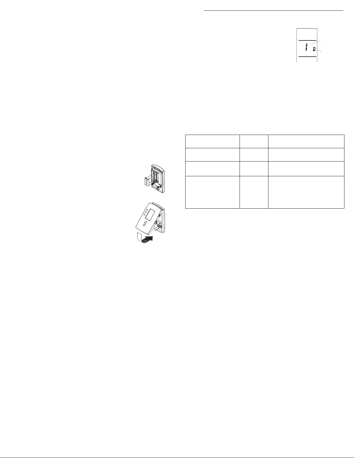
2.5 Battery installation
Install two AAA batteries on the back of the thermostat
faceplate as shown.
2.6 Thermostat mounting
Align the two brackets on the top of the
thermostat with the corresponding slots on the
top of the wallplate.
Push the faceplate against the wallplate.
Tighten the screw at the bottom of the
thermostat.
Follow the procedure below to personalize
and configure the thermostat according to the
heating/cooling system.
Configuration menu
Press and simultaneously (for
three seconds) until the display appears
as shown on the right.
Press or to change the option.
Press and for one second to advance to the next function.
When the last function is displayed, press and for three
seconds to save any changes and exit the menu.
NOTE: If you do not press any button for 60 seconds while you are in
the setup menu, the thermostat automatically saves any changes
made and exits the menu. For the RTH221 programmable model
only, at any time you can save the changes and exit by pressing the
Run button.
Function
Temperature
1
display format
Time display
2
3
1
Applies to RTH221 programmable model only.
2
The cooling cycle is fixed at 3 cycles per hour.
1
format
Heating cycles
per hour
2
Default
setting
0
0
5
Options
0: Fahrenheit
1: Celsius
0: 12-hour display
1: 24-hour display
• 1: 60 min (steam, gravity)
• 3: 20 min (hot water, 90%+
high-efficiency furnace)
• 5: 12 min (gas or oil)
• 9: 6.7 min (electric)
3.
RT H111/ RTH 221 2/8
Page 3
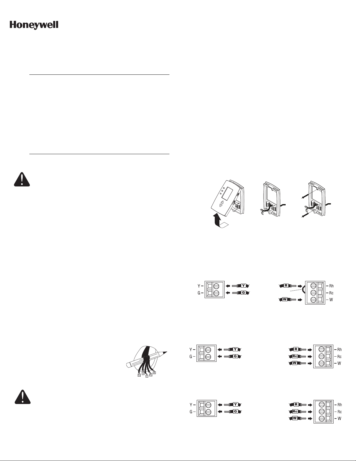
Figure 1
Figure 2
Figure 3
cavalier
Rh, 4 ou V
R
W1 ou H
Y1 ou M
F
RTH111/RTH221
Guide d’installation
Thermostats programmable et non programmable
Les thermostats programmables RTH111/RTH221 peuvent servir à
commander les appareils suivants :
• Fournaise au gaz, mazout, électrique — 2 ou 3 fils
• Climatiseur central — 2 ou 3 fils
• Chauffage à eau chaude (vapeur ou gravité) avec ou sans pompe — 2 fils
• Système millivolts — 2 fils
• Chauffage central avec climatisation — 4 ou 5 fils
REMARQUE : Ce thermostat n'est pas compatible avec les
thermopompes ou les systèmes multi-étages.
Introduction
Installation
MISE EN GARDE : RISQUE DE CHOC ÉLECTRIQUE
Peut provoquer des chocs électriques ou endommager le
matériel. Couper l’alimentation électrique avant
d’effectuer le raccordement.
2.1 Retirer l'ancien thermostat
POUR ÉVITER TOUT RISQUE DE CHOC ÉLECTRIQUE, COUPER
L'ALIMENTATION DU SYSTÈME DE CHAUFFAGE.
Retirer l'ancien thermostat pour accéder aux fils.
MISE EN GARDE : Si l'ancien thermostat était installé sur une
boîte électrique, il pourrait avoir été alimenté par du 120/240
volts. Dans ce cas, le nouveau thermostat ne convient pas. Si
vous n’êtes pas certain de la tension d’alimentation, consulter un
électricien.
Identifier et étiqueter chaque fil (avec la lettre de la borne
correspondante) et débrancher les fils des bornes.
REMARQUE 1 : Ne pas tenir compte de la couleur des fils;
utiliser les lettres pour identifier les types de fil.
REMARQUE 2 : Si des fils ne sont pas branchés aux bornes de
l’ancien thermostat, il n’est pas nécessaire de les étiqueter,
puisque vous n’aurez pas à les brancher au nouveau
thermostat.
Au besoin, dénuder l'extrémité de chacun des fils (maximum de
6 mm).
Enrouler les fils autour d'un crayon pour les
empêcher de glisser à l’intérieur du mur.
Si l'ouverture dans le mur est trop grande,
l'isoler au moyen d'un matériau
ininflammable pour éviter tout courant d'air
derrière le thermostat.
AVIS SUR LE MERCURE
Si le nouveau thermostat remplace un ancien régulateur
contenant un contact à mercure, ne pas jeter l’ancien
régulateur à la poubelle. Communiquer avec le service local
de cueillette des déchets pour obtenir de l’information sur le
recyclage ou sur la bonne façon de se débarrasser d’un
ancien régulateur contenant un contact à mercure.
1.
2.2 Installation de la plaque murale
Desserrer la vis de blocage au bas du thermostat. Noter que la
vis est captive et ne peut pas être enlevée de la plaque murale.
Séparer le thermostat de la plaque murale selon la figure 1.
Placer la plaque murale contre le mur et marquer au crayon
l’emplacement des trous.
REMARQUE : La mise à niveau est purement esthétique et
n'aura aucun effet sur le fonctionnement du thermostat.
Percer les trous aux endroits marqués et insérer les chevilles
d’ancrage fournies.
2.
Passer les fils par la grande ouverture située au centre inférieur
de la plaque murale selon la figure 2.
Fixer la plaque murale au mur avec les vis de montage fournies
selon la figure 3.
2.3 Câblage
Il est important que vous jumeliez les étiquettes des fils aux bornes
correspondantes sur le thermostat.
REMARQUE : Selon votre système, vous n’aurez peut-être pas à utiliser toutes les bornes.
Enlever le cavalier (fil) entre les bornes Rc et Rh si vous avez les fils
Rh et Rc tel que montré dans l’illustration suivante.
Si une étiquette de fil ne correspond pas à aucune désignation de
borne sur le thermostat, se référer à l'illustration suivante pour trouver une autre étiquette qui peut correspondre à cette borne.
RT H111/ RTH 221 3/8
Page 4

Ne pas brancher les fils identifiés comme C, C1, X ou B,
Numéro de
la fonction
Numéro
de l’option
car ces fils ne sont pas utilisés avec ce thermostat.
Couvrir le bout dénudé de ces fils avec du ruban
électrique pour les empêcher d’entrer en contact et de
court-circuiter les autres fils.
2.4 Réglage du ventilateur
REMARQUE : Ce réglage ne s’applique pas s’il n’y a pas de
ventilateur relié à la borne G.
Le cavalier de réglage est situé au dos de la façade du thermostat. Il
sert à déterminer le fonctionnement du ventilateur en mode
Automatique.
• HG (réglage d’usine) : Laisser le cavalier dans cette position dans
le cas d’un système de chauffage au gaz ou au mazout. Dans
cette position, le ventilateur est commandé par le système de
chauffage et est activé uniquement lorsque l’air du plénum est
suffisamment chaud.
• HE : Placer le cavalier dans cette position dans le cas d’un
système de chauffage électrique. Dans cette position, le
ventilateur est activé aussitôt qu’il y a une demande de chauffage.
Si le réglage est incorrect :
• Si le mauvais réglage (HE) est utilisé dans un système de
chauffage au gaz ou au mazout, chaque fois que le chauffage
démarrera, vous sentirez l'air froid qui circule puisque le
ventilateur commencera à fonctionner avant que l'air n’ait le temps
de se réchauffer.
• Si le mauvais réglage (HG) est utilisé dans un système de
chauffage électrique, le ventilateur ne démarrera pas lors d’une
demande de chauffage.
2.5 Installation des piles
Insérer deux piles AAA à l’arrière du thermostat tel
qu’illustré.
Menu de configuration
Suivre les étapes ci-dessous pour
personnaliser et configurer le thermostat
selon le système de chauffage/climatisation.
Appuyer simultanément sur et
(pendant trois secondes) jusqu’à ce que
l’affichage ci-contre apparaisse à l’écran.
Appuyer sur ou pour changer
d’option.
Appuyer sur et pendant une seconde pour passer à la
fonction suivante.
Lorsque la dernière fonction est affichée, appuyez sur et
pour enregistrer toutes les modifications et sortir du menu..
REMARQUE : Si vous n’appuyez sur aucun bouton pendant 60
secondes lorsque vous êtes dans le menu, le thermostat enregistrera
toutes les modifications et sortira du menu automatiquement. Pour le
modèle programmable RTH221, vous pouvez enregistrer en tout
temps les modifications et sortir du menu en appuyant Run.
Fonction
Format d’affichage
1
de la température
Format d’affichage
2
de l’heure
Cycles de
chauffage par
3
heure
1
Ne s’applique qu’au modèle programmable RTH221.
2
Le nombre de cycles de climatisation est fixé à 3 par heure.
1
2
Réglage
par défaut
0
0
5
Options
0 : Fahrenheit
1 : Celsius
0 : format 12 heures
1 : format 24 heures
• 1 : 60 min (vapeur, gravité)
• 3 : 20 min (eau chaude,
fournaise 90 %+ haute efficacité)
• 5 : 12 min (gaz ou mazout)
• 9 : 6,7 min (électrique)
3.
2.6 Montage du thermostat
Aligner les deux languettes sur le haut de la
façade aux fentes correspondantes sur le haut
de la plaque murale.
Pousser la façade contre la plaque murale.
Serrer la vis située sous le thermostat.
RT H111/ RTH 221 4/8
Page 5

Figura 3
Figura 2
Figura 1
cable de puente
RTH111/RTH221
Guía de instalación
Termostatos programables y no programables
Los termostatos programables RTH111/RTH221 pueden usarse para
controlar los siguientes aparatos:
• Calefactor a gas, aceite o eléctrico de 2 ó 3 cables
• Aire acondicionado central de 2 ó 3 cables
• Sistema de agua caliente (vapor o gravedad) con o sin bomba de
• Sistema de milivoltios de 2 cables
• Calefacción central con aire acondicionado - 4 ó 5 cables
NOTA: este termostato no es compatible con bombas de calor ni con
sistemas de etapas múltiples.
Introducción
2 cables
Instalación
ADVERTENCIA: PELIGRO DE ELECTROCUCIÓN
Se puede producir un choque eléctrico o dañarse el
equipo. Desconectarlo de la fuente de energía antes de
comenzar la instalación.
2.1 Extracción del viejo termostato
PARA EVITAR EL RIESGO DE DESCARGAS ELÉCTRICAS,
CORTAR LA ALIMENTACION DEL SISTEMA DE CALEFACCIÓN.
Extraer el viejo termostato para acceder a los cables.
ATE NCIÓN: si el viejo termostato está montado en una caja
eléctrica, la alimentación es probablemente de 120/240 volts.
En este caso, este termostato no puede utilizarse. Si no se
supiera con certeza el voltaje de la fuente de alimentación,
ponerse en contacto con un electricista.
Identificar y rotular los cables (con la letra correspondiente que
figura en el terminal de cada cable) y desconectarlos de los
terminales.
NOTA 1: ignorar los colores de los cables y usar sólo letras para
identificar los diferentes cables.
NOTA 2: si un cable no estuviera conectado a los terminales de
su viejo termostato no es necesario ponerle etiqueta, puesto que
no estará conectado tampoco en el nuevo termostato.
Si fuera necesario, pelar el extremo de cada cable (un máximo
de 1/4 de pulgada).
Enroscar los cables alrededor de un lápiz
para evitar que caigan en el hueco de la
pared.
Si el hueco de la pared fuera muy grande,
aislarlo con un material no inflamable para
evitar que haya corrientes de aire detrás
del termostato.
1.
AVISO SOBRE EL MERCURIO
En caso de que este producto reemplace un control que
contenga mercurio en tubo sellado, no arrojar el viejo
control a la basura. Comunicarse con la autoridad local
para el manejo de desechos a fin de obtener
instrucciones sobre el reciclado y la correcta eliminación
de este tipo de producto.
2.2 Instalación de la placa mural
Destornillar el tornillo de anclaje que está en la parte inferior del
termostato. Tener en cuenta que el tornillo está prisionero y no
puede retirarse de la placa.
2.
Separar el termostato de la placa mural según se muestra en la
figura 1.
Colocar la placa mural contra la pared y marcar los agujeros con
un lápiz.
NOTA: la nivelación se hace por razones estéticas solamente y
no afectará el funcionamiento del termostato.
Perforar los agujeros en el lugar marcado e introducir los
anclajes de pared provistos.
Pasar los cables por la gran abertura situada en el centro de la
parte inferior de la placa mural, según se muestra en la figura 2.
Fijar la placa mural a la pared con los tornillos de montaje
provistos, según se muestra en la figura 3.
2.3 Cableado
Es importante hacer corresponder las etiquetas de los cables con las
de los terminales correspondientes del termostato.
NOTA: según cuál sea el sistema, puede que no sea necesario
conectar todos los terminales.
RT H111/ RTH 221 5/8
Page 6

Retirar el cable de puente entre los terminales Rh y Rc, si estuvieran
Rh, 4 o V
R
W1 o H
Y1 o M
F
Número
de la
función
Número
de la
opción
presentes los dos cables Rh y Rc, como se indica en la siguiente
ilustración:
Referirse a la siguiente ilustración en el caso de que un cable no
correspondiera con la identificación de un terminal en el termostato,
para encontrar el cable alternativo correspondiente:
No conectar los cables identificados con las letras C, C1,
X o B, puesto que dichos cables no se utilizan con este
termostato. Cubrir los extremos desnudos de los cables
con cinta aislante, para que no se toquen y no entren en
cortocircuito con otros cables.
2.4 Ajuste del ventilador
NOTA: este ajuste no se aplica si no hubiera un ventilador conectado
al terminal G.
El puente está situado en la parte posterior de la tapa del termostato
y determina el funcionamiento del ventilador en modo automático.
• HG (ajuste de fábrica): dejar el puente en esta posición en el caso
de un sistema de calefacción a gas o a aceite. En esta posición, el
ventilador está controlado por el sistema de calefacción y se
activa únicamente cuando el aire del distribuidor de aire está
suficientemente caliente.
• HE: colocar el puente en esta posición en el caso de un sistema
de calefacción eléctrico. En esta posición, el ventilador se activa
en cuanto hay una demanda de calefacción.
Menú de configuración
Seguir las etapas a continuación para
personalizar y configurar el termostato según
el sistema de calefacción/enfriamiento.
Presionar y (durante tres segundos)
hasta que la pantalla aparecerá como en
la figura a la derecha.
Presionar o para cambiar de opción.
Presionar y durante un segundo para pasar a la función
siguiente.
Cuando se visualiza la última función, se presiona y
durante tres segundos para salir del menú.
NOTA: si no se presiona ningún botón durante 60 segundos estando
en el menú de ajuste, el termostato salva los cambios
automáticamente y sale del menú. En al modelo programable
RTH221 solamente se pueden salvar los cambios en cualquier
momento y salir presionando el botón Run.
Función
Formato de visualización
1
de la temperatura
Formato de visualización
2
de la hora
Ciclos de calefacción por
3
hora
1
Se aplica solamente al modelo programable RTH221.
2
Los ciclos de enfriamiento están fijos en 3 ciclos por hora.
1
2
Ajuste por
defecto
0
0
5
Opciones
0: Fahrenheit
1: Celsius
0: formato de 12 horas
1: formato de 24 horas
• 1: 60 min. (vapor, gravedad)
• 3: 20 min. (agua caliente,
calefactor 90%+ alto rendimiento)
• 5: 12 min. (gas o aceite)
• 9: 6,7 min. (eléctrica)
3.
Ajuste incorrecto del puente:
• Ajuste incorrecto HE en un sistema de calefacción a gas o a
aceite: cuando la calefacción arranca, se sentirá al principio que
sale aire frío de las rejillas de ventilación, porque el ventilador
comienza a funcionar antes de que el aire haya tenido tiempo de
calentarse.
• Ajuste incorrecto HG en un sistema eléctrico: el ventilador no
funcionará cuando la calefacción esté activada.
2.5 Instalación de las pilas
Instalar dos pilas AAA en la parte trasera de la tapa del
termostato, como se indica.
2.6 Montaje del termostato
Alinear las dos lengüetas de la parte superior
de la tapa con las ranuras conrrespondientes
en la parte superior de la placa mural.
Empujar la tapa contra la placa mural.
Ajustar el tornillo en la base del termostato.
RT H111/ RTH 221 6/8
Page 7

RT H111/ RTH 221 7/8
Page 8

RT H111/ RTH 221 8/8Printed in USA 08/2011
 Loading...