

Page 1
RTH1120
Non-programmable Electronic Thermostat
Installation and User Guide
1. Introduction
The RTH1120 non-programmable thermostat can be used to control:
• a gas, fuel oil or electric furnace - 2 or 3 wires
• a central air conditioner - 2 or 3 wires
• a hot water system with or without pump - 2 wires
• a millivolt system - 2 wires
• a central heating and cooling system - 4 or 5 wires
Note: This thermostat is not compatible with heat pumps or multi-
stage systems.
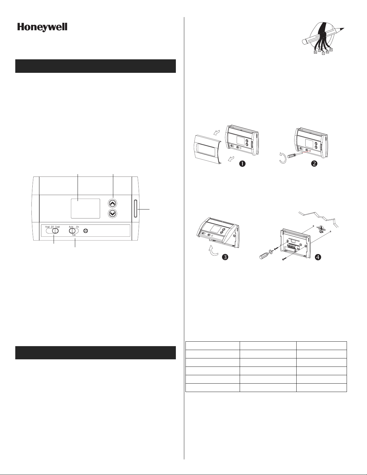
Adjustment
Display
buttons
Backlight
button
q Wrap the wires around a pencil to prevent
them from falling into the wall.
r If the hole in the wall is too big, insulate it
using a non-flammable material in order
to avoid air draughts behind the thermostat.
2.2 Installing the New Baseplate
For a new installation, choose a location approximately 5 feet
(1.5 m) above the floor and on an inside wall. Avoid draughty
areas (top of staircase, air outlet, etc.), dead air spots (behind
doors), direct sunlight or areas near concealed pipes or chimneys.
n Remove the thermostat faceplate.
o Loosen the locking screw to separate the thermostat from its
baseplate (the screw cannot be completely removed).
System operating
mode selector
Features
• System operating mode selection: heat, cool or off
• Fan operating mode selection: automatic or on (continuous)
• Programmable heating and cooling cycle lengths: 10, 12, 15, 20
or 30 minutes
• Temperature display in °F or °C
• Backlit display
• Battery replacement indicator
• Interchangeable faceplates (titanium, charcoal & taupe)
Fan operating
mode selector
2. Installation
2.1 Removing the Old Thermostat
IN ORDER TO AVOID ANY RISK OF ELECTRIC SHOCK, CUT
POWER TO THE HEATING SYSTEM.
n Remove the old thermostat to access the wires.
Attention: If the old thermostat was mounted onto an electrical box,
it was probably powered by 120/240 volts. In this case, this thermostat cannot be used.
o Identify and label each wire (with the corresponding letter on
the wire terminal) and remove them from the terminals.
p If necessary, strip the end of each wire (maximum of 1/4 inch).
p Tilt the thermostat upwards.
q Mark and bore the appropriate mounting holes (using a 3/16”
drill bit) or use the existing holes. Insert the plastic anchors.
r Pass the wires through the opening of the baseplate and fix the
baseplate to the wall using the screws provided.
2.3 Connecting the Thermostat
Refer to the following table for matching the wire labels with the
thermostat terminals.
RTH1120 terminals Description Wire labels
Rh Heating power supply Rh, R, 4, V
Rc Cooling power supply Rc, R
W Heating signal W, W1, H
Y Cooling signal Y, Y1, M
GFan G, F
Note: Do not connect wires identified as C, X or B. Wrap the bare
end of these wires with electrical tape.
Important: The red jumper wire between Rh and Rc terminals must
be removed in a 5-wire installation.
RTH1120 69-1876ES-1 29/11/06 1/4
Page 2
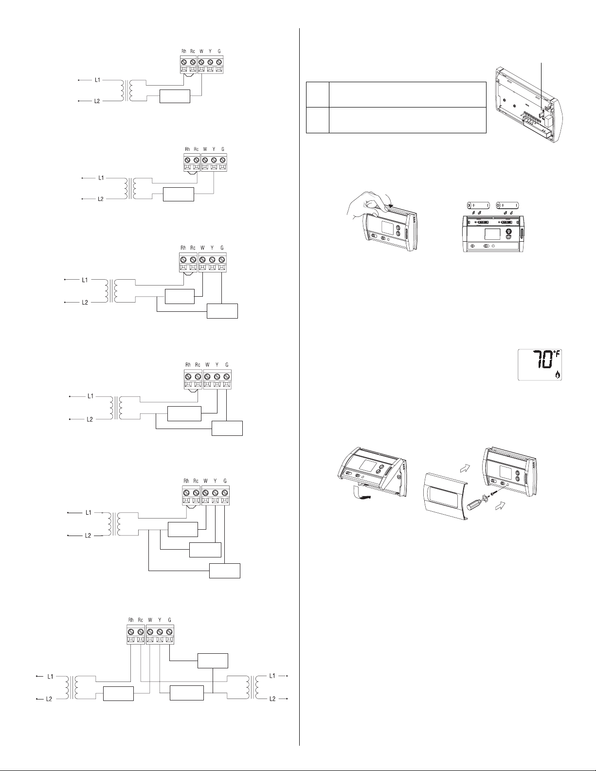
2.3.1 2-wire Heating
2.3.2 2-wire Cooling
2.3.3 3-wire Heating
2.3.4 3-wire Cooling
Heat relay
Cool relay
Heat relay
Cool relay
Fan relay
Fan relay
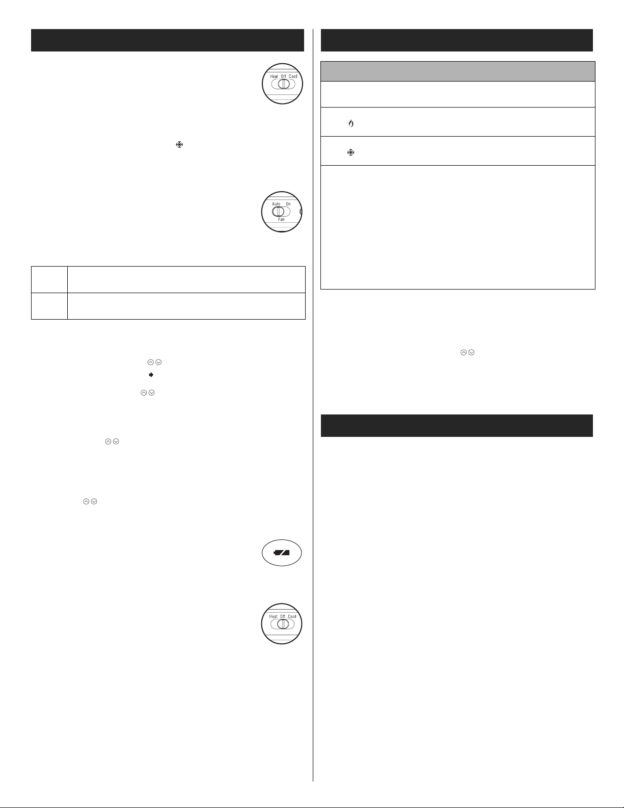
2.4 Setting J2 Jumper
The jumper specifies how the fan will operate
when it is placed in automatic mode (see section 3.2).
Leave the jumper in this position if you
HG
have a gas or oil heating system.
Move the jumper to this position if you
HE
have an electric heating system.
JP2 jumper
2.5 Installing the Batteries
n Pull out the battery cover.
o Install the batteries as shown. Observe the polarity.
p Reinstall the battery cover. You will hear a clicking sound.
After the batteries are installed, the thermostat performs a series of
tests for approximately 5 seconds.
Afterwards, the screen displays the actual temperature. It is normal that the displayed temperature will
be higher than the ambient temperature if you hold
the thermostat in your hands. It will display the
ambient temperature after the thermostat is
installed on the wall. By default, the setpoint is 70°F (21°C).
2.6 Completing the Installation
2.3.5 4-wire Heating and Cooling
Heat relay
Cool relay
Fan relay
2.3.6 5-wire Heating and Cooling
Fan relay
Heat relay
Note: Remove the red jumper wire between terminals Rc and Rh.
Cool relay
n Once the baseplate and the batteries are installed, mount the
thermostat on the baseplate.
o Secure the thermostat using the locking screw and install the
faceplate.
p Apply power back to the system.
RTH1120 69-1876ES-1 29/11/06 2/4
Page 3
3. Basic Functions
3.1 System Operating Mode
Use the selector switch to place the system in Heating
mode (HEAT) or Cooling mode (COOL), or to turn the
system off.
Note: When you place the thermostat in Cooling mode, you might
need to wait up to five minutes before cooling can start. This is a
safety feature for the compressor. will flash on the screen until
cooling can start again.
3.2 Fan Operating Mode
Use the selector switch to set the fan to automatic
mode (AUTO) or continuous mode (ON).
Note: This switch is not used if you have a 2-wire
installation as the fan is not connected to the thermostat.
AUTO
3.3 Displaying the Temperature
The actual temperature is normally displayed. To view the setpoint,
press once on either of the buttons. The setpoint is displayed
for 5 seconds along with the icon.
Note: Pressing any of the buttons more than once will change
the setpoint.
The fan operates only when the heating or cooling system is On (typical setting).
The fan operates continuously. Use this setting to
ON
improve air circulation and air cleaning.
4. Configuration Menu
DISPLAY DESCRIPTION DEFAULT SETTINGS
Temperature
display
Heating cycles
per hour
Cooling cycles
per hour
1
When either the heating or cooling parameter is displayed, use
the system mode selector switch to alternate between the two
parameters.
2
For optimal heating control, use the setting that matches your
system as follows: 2=30 min (steam or gravity), 3=20 min (hot
water or 90%+ high-efficiency furnace),
4=15 min (gas or oil), 5=12 min (alternate setting for gas or oil),
6=10 min (electric).
3
The corresponding cooling cycle lengths are as follows: 2=30
min, 3=20 min, 4=15 min, 5=12 min, 6=10 min.
1
1
n To access the configuration menu, press the backlight button
for 3 seconds.
o To go to the next parameter (menu item), briefly press the back-
light button.
p To modify a parameter, press .
q Repeat steps 2 and 3 if necessary.
r Press the backlight button for 3 seconds to exit the configura-
tion menu.
°F °C or °F
4
4
2, 3, 4, 5 or 6
2, 3, 4, 5 or 6
2
3
3.4 Setting the Temperature
Press one of the buttons until the desired temperature is displayed.
3.5 Backlight
The display illuminates for 12 seconds when the backlight button or
either of the buttons is pressed.
3.6 Battery Replacement Indicator
An icon appears when the batteries need replacement.
This icon will flash for 120 days, then the thermostat
will cut power to the heating/cooling unit. The icon disappears once the batteries are replaced. The temperature settings are saved and do not need to be re-entered.
Warning: Before removing the batteries, place the
system switch on the thermostat to Off. Otherwise, the
heating/cooling unit might still be running even after
the batteries are removed.
5. Technical Specifications
Power supply: 2 AA batteries
Maximum load: 1 A @ 24 Vac per output
Setpoint range (heating): 41 to 82°F (5 to 28°C)
Setpoint range (cooling): 59 to 95°F (15 to 35°C)
Display range: 23 to 122°F (-5 to 50°C)
Storage temperature: -2 to 122°F (-20 to 50°C)
Temperature display resolution: 1°F (0.5°C)
Accuracy: ± 1°F (0.5°C)
Heating/cooling cycle lengths: 10, 12, 15, 20 or 30 minutes (pro-
grammable)
Compressor short-cycle protection (minimum off time): 5 minutes
Data memory: non-volatile
Dimensions: 5 in. x 3 in. x 1 in. (127 mm x 75 mm x 28 mm)
RTH1120 69-1876ES-1 29/11/06 3/4
Page 4

6. Warranty
Honeywell warrants this product, excluding battery, to be free from
defects in the workmanship or materials, under normal use and service, for a period of one (1) year from the date of purchase by the
consumer. If at any time during the warranty period the product is
determined to be defective or malfunctions, Honeywell shall repair
or replace it (at Honeywell's option).
If the product is defective,
(i) return it, with a bill of sale or other dated proof of purchase, to
the place from which you purchased it, or
(ii) call Honeywell Customer Care at 1-800-468-1502. Customer
Care will make the determination whether the product should
be returned to the following address: Honeywell Return Goods,
Dock 4 MN10-3860, 1885 Douglas Dr N, Golden Valley, MN
55422, or whether a replacement product can be sent to you.
This warranty does not cover removal or reinstallation costs. This
warranty shall not apply if it is shown by Honeywell that the defect or
malfunction was caused by damage which occurred while the product was in the possession of a consumer.
Honeywell's sole responsibility shall be to repair or replace the product within the terms stated above. HONEYWELL SHALL NOT BE
LIABLE FOR ANY LOSS OR DAMAGE OF ANY KIND, INCLUDING ANY INCIDENTAL OR CONSEQUENTIAL DAMAGES
RESULTING, DIRECTLY OR INDIRECTLY, FROM ANY BREACH
OF ANY WARRANTY, EXPRESS OR IMPLIED, OR ANY OTHER
FAILURE OF THIS PRODUCT. Some states do not allow the exclusion or limitation of incidental or consequential damages, so this limitation may not apply to you.
THIS WARRANTY IS THE ONLY EXPRESS WARRANTY HONEYWELL MAKES ON THIS PRODUCT. THE DURATION OF ANY
IMPLIED WARRANTIES, INCLUDING THE WARRANTIES OF
MERCHANTABILITY AND FITNESS FOR A PARTICULAR PURPOSE, IS HEREBY LIMITED TO THE ONE-YEAR DURATION OF
THIS WARRANTY. Some states do not allow limitations on how
long an implied warranty lasts, so the above limitation may not apply
to you.
This warranty gives you specific legal rights, and you may have
other rights which vary from state to state.
If you have any questions concerning this warranty, please write
Honeywell Customer Relations, 1985 Douglas Dr, Golden Valley,
MN 55422 or call 1-800-468-1502. In Canada, write Retail Products
ON15-02H, Honeywell Limited/Honeywell Limitée, 35 Dynamic
Drive, Scarborough, Ontario M1V4Z9.
7. Customer Assistance
If you have any questions about the operation of your thermostat,
please go to http://yourhome.honeywell.com, or call Honeywell
Customer Care toll-free at 1-800-468-1502.
RTH1120 69-1876ES-1 29/11/06 4/4
Page 5

RTH1120
Termostato electrónico no programable
Instalación y guía para el usuario
1. Introducción
El termostato no programable RTH1120 puede usarse para
controlar:
• Un sistema de calefacción que funcione con gas, aceite
combustible o electricidad de 2 ó 3 cables
• Un acondicionador de aire central de 2 ó 3 cables
• Un sistema de agua caliente con bomba o sin ella de 2 cables
• Un sistema de milivoltios de 2 cables
• Un sistema de calefacción y de enfriamiento central de 4 ó 5
cables
Nota: Estos termostatos no son compatibles con bombas de calor ni con
sistemas de etapas múltiples.
p Si es necesario, pele el extremo de cada cable (un máximo de
1/4 de pulgada).
q Enrosque los cables alrededor de un
lápiz para evitar que caigan en el hueco
de la pared.
r Si el hueco de la pared es muy grande,
aíslelo con un material no inflamable para
evitar que haya corrientes de aire detrás
del termostato.
2.2 Instalación de la nueva placa de base
Para una instalación nueva, elija una ubicación que esté
aproximadamente 1.5 m (5 pies) sobre el suelo y encima una
pared interna. Evite áreas donde haya corrientes de aire (parte
superior de la escalera, salida de aire, etc.), áreas donde el aire
esté viciado (detrás de las puertas), espacios que reciban la luz
directa del sol o áreas cercanas a caños ocultos o a
chimeneas.
Pantalla
Selector del modo
de funcionamiento
del sistema
Características
• Selección del modo de funcionamiento del sistema: calor, frío o
apagado
• Selección del modo de funcionamiento del ventilador: automático
o encendido (continuo)
• Duración programable de los ciclos de calefacción y
enfriamiento: 10, 12, 15, 20 ó 30 minutos
• Temperatura en ºF o en ºC
• Pantalla iluminada
• Indicador de cambio de baterías
• Placas frontales intercambiables (titanio, carbón y gris pardo)
Selector del modo
de funcionamiento
del ventilador
Botones
de ajuste
Botón de
iluminación
posterior
n Quite la placa frontal del termostato.
o Afloje el tornillo de seguridad para separar el termostato de la
placa de base (no se puede sacar el tornillo por completo).
p Incline el termostato hacia arriba.
q Marque y haga los agujeros de montaje adecuados (con una
broca para taladro de 3/16 de pulgada) o use los agujeros que
ya estén hechos. Inserte las anclas de expansión plásticas.
r Pase los cables a través de la abertura de la placa de base y
ajústela en la pared con los tornillos que vienen incluidos.
2.3 Conexión del termostato
Vea el siguiente cuadro para hacer coincidir las etiquetas de los
cables con las terminales del termostato.
2. Instalación
2.1 Extracción del termostato viejo
PARA EVITAR EL RIESGO DE DESCARGAS ELECTRICAS,
CORTE LA ALIMENTACION ELECTRICA DEL SISTEMA DE
CALEFACCION.
n Extraiga el termostato viejo para acceder a los cables.
Atención: Si el termostato viejo está montado sobre una caja
eléctrica, probablemente, la alimentación sea de 120/240 voltios.
En ese caso, no se puede usar el termostato.
o Identifique y rotule los cables (con la letra correspondiente en
la terminal de cada cable) y quítelos de las terminales.
RTH1120 69-1876ES-1 29/11/06 1/4
Terminales RTH1120 Descripción Etiquetas de los cables
Rh
Rc
W Señal de calefacción W, W1, H
Y Señal de enfriamiento Y, Y1, M
G Ventilador G, F
Nota: No conecte los cables que estén identificados como C, X o B.
Envuelva los extremos desnudos de estos cables con cinta aislante.
Importante: En las instalaciones de 5 cables, hay que quitar el puente
rojo ubicado entre las terminales Rc y Rh.
Alimentación eléctrica para la calefacción
Alimentación eléctrica
para el enfriamiento
Rh, R, 4, V
Rc, R
Page 6

2.3.1 Calefacción con dos cables
2.4 Configuraciones del puente J2
El puente especifica como funcionará el ventilador cuando se lo coloque en modo
automático (vea la sección 3.2).
Puente JP2
2.3.2 Enfriamiento con dos cables
2.3.3 Calefacción con tres cables
2.3.4 Enfriamiento con tres cables
Relé de la
calefacción
Relé del
enfriamiento
Relé de la
calefacción
Relé del
enfriamiento
Relé del
ventilador
Relé del
ventilador
Si tiene un sistema de calefacción que
HG
funcione con gas o con aceite, deje el
puente en esta posición.
Si tiene un sistema de calefacción
HE
eléctrico, mueva el puente hacia esta
posición.
2.5 Instalación de las baterías
n Retire la tapa de las baterías.
o Instale las baterías como se indica en la figura. Preste atención
a la polaridad.
p Vuelva a colocar la tapa de las baterías. Escuchará un clic.
Una vez instaladas las baterías, el termostato realiza una serie de
pruebas durante aproximadamente 5 segundos.
Luego, la pantalla muestra la temperatura real. Es
normal que la temperatura que aparece en la
pantalla sea más alta que la temperatura ambiente
si usted tiene el termostato en las manos. El
termostato mostrará la temperatura ambiente
cuando esté colocado en la pared. Por defecto, el
punto de referencia es 70 ºF (21 ºC).
2.6 Finalización de la instalación
2.3.5 Calefacción y enfriamiento con cuatro cables
Relé de la
calefacción
Relé del
enfriamiento
Relé del
ventilador
2.3.6 Calefacción y enfriamiento con cinco cables
Relé del
ventilador
Relé de la
calefacción
Nota: Quite el puente rojo ubicado entre las terminales Rc y Rh.
Relé del
enfriamiento
n Una vez que la placa de la base y las baterías estén
colocadas, monte el termostato sobre la placa de la base.
o Ajuste el termostato usando el tornillo de seguridad
correspondiente e instale la placa frontal.
p Vuelva a conectar la alimentación eléctrica.
RTH1120 69-1876ES-1 29/11/06 2/4
Page 7

3. Funciones básicas
4. Menú de configuración
3.1 Modo de funcionamiento del sistema
Use el interruptor de selección para colocar el
sistema en el modo de calefacción (HEAT) o en el
modo de enfriamiento (COOL), o para apagar el
sistema.
Nota: Cuando coloque el termostato en el modo de enfriamiento,
quizás tenga que esperar cinco minutos antes de que comience a
enfriar. Esta es una característica de seguridad para el compresor.
El indicador destellará en la pantalla hasta que el enfriamiento
comience nuevamente.
3.2 Modo de funcionamiento del ventilador
Use el interruptor de selección para colocar el
ventilador en el modo automático (AUTO) o en el
modo continuo (ON).
Nota: Este interruptor no se usa si tiene una
instalación de 2 cables, porque, en este caso, el
ventilador no está conectado al termostato.
El ventilador funciona solamente cuando el
AUTO
ON
sistema de calefacción o de enfriamiento está
encendido (configuración típica).
El ventilador funciona continuamente. Use esta
configuración para mejorar la circulación y la
limpieza del aire.
3.3 Indicación de la temperatura
Normalmente, se indica la temperatura real. Para ver el punto de
referencia, pulse una vez uno de los botones . El punto de
referencia aparecerá durante 5 segundos, junto con el icono .
Nota: Al pulsar cualquiera de los botones más de una vez se
cambia el punto de referencia.
3.4 Ajuste de la temperatura
Pulse uno de los botones hasta que se muestre la temperatura
deseada.
3.5 Iluminación posterior
La pantalla se ilumina durante 12 segundos cuando se presiona el
botón de iluminación posterior o cualquier otro botón .
3.6 Indicador de cambio de baterías
Cuando hay que cambiar las baterías, aparece un icono.
Este icono destellará durante 120 días, y luego el
termostato cortará la alimentación eléctrica de la unidad
de calefacción y enfriamiento. Cuando se cambian las
baterías, el icono desaparece. Los valores de
temperatura establecidos no se borran durante el corte de energía.
Advertencia: Antes de quitar las baterías, coloque el
interruptor del sistema del termostato en Off ("Apagado").
De lo contrario, la unidad de calefacción y enfriamiento
seguirá funcionando aunque se hayan extraído las baterías.
PANTALLA DESCRIPCION
Indicador de temperatura °F °C o °F
Ciclos de calefacción por
1
hora
Ciclos de enfriamiento por
1
hora
1
Cuando se muestre el parámetro de calefacción o de
enfriamiento, use el interruptor de selección de modo del sistema
para alternar entre los dos parámetros.
2
Para un control de calefacción óptimo, use el programa que se
ajusta a su sistema. Este programa se detalla a continuación: 2 =
30 min (vapor, gravedad), 3 = 20 min (agua caliente, 90% +
calefacción de alto rendimiento), 4 = 15 min (gas o aceite),
5 = 12 min (programa alternativo para gas o aceite), 6 = 10 min
(electricidad).
3
Las duraciones del ciclo de enfriamiento correspondientes son:
2 = 30 min, 3 = 20 min, 4 = 15 min, 5 = 12 min, 6 = 10 min
PREDE-
TERMINADO
4
4
OPCIONES
2, 3, 4, 5 ó 6
2
2, 3, 4, 5 ó 6
3
n Para acceder al menú de configuración, presione el botón de ilumi-
nación posterior durante 3 segundos.
o Para avanzar al siguiente parámetro (elemento del menú), pre-
sione brevemente el botón de iluminación posterior.
p Para modificar un parámetro, presione .
q Repita los pasos 2 y 3 si es necesario.
r Para salir del menú de configuración, presione el botón de ilumi-
nación posterior durante 3 segundos.
5. Especificaciones técnicas
Fuente de alimentación: 2 baterías AA
Carga máxima: 1 A a 24 V CA por salida
Rango del punto de referencia (calefacción): de 41°F a 82 °F (de 5
°F a 28 °C)
Rango del punto de referencia (enfriamiento): de 59 °F a 95 °F (de
15 °F a 35 °C)
Rango de la pantalla: de 23 °F a 122 °F (de -5 °C a 50 °C)
Temperatura de almacenamiento: de -2 °F a 122 °F (de -20 ºC a 50
°C)
Resolución de la pantalla indicadora de temperatura: 1 °F (0,5 °C)
Precisión: ± 1 °F (0,5 °C)
Duraciones de los ciclos de calefacción y enfriamiento
(programable): 10, 12, 15, 20 ó 30 minutos
Protección de ciclos cortos del compresor (tiempo mínimo de
apagado): 5 min
Memoria de datos: no volátil
Dimensiones: 5 x 3 x 1 pulgadas (127 mm x 75 mm x 28 mm)
RTH1120 69-1876ES-1 29/11/06 3/4
Page 8

6. Garantía
Honeywell garantiza por un período de un (1) año, a partir de la
fecha de compra por el consumidor, que este producto, sin incluir
las baterías, no presentará defectos en los materiales ni en lo
referente a la mano de obra, en condiciones normales de uso y de
servicio. Si en cualquier momento, durante el período de vigencia
de la garantía, se determina que el producto es defectuoso o que
funciona mal, Honeywell lo reparará o lo reemplazará (a elección
de Honeywell).
Si el producto es defectuoso:
I. Devuélvalo al lugar donde lo compró, acompañado por la
factura de compra o de otra prueba de compra que incluya la
fecha.
II. Llame al servicio de atención al cliente de Honeywell, al 1-800-
468-1502. El servicio de atención al cliente determinará si el
producto debe devolverse a la siguiente dirección: Honeywell
Return Goods, Dock 4 MN10-3860, 1885 Douglas Dr N,
Golden Valley, MN 55422; o si se le enviará un producto de
reemplazo.
Esta garantía no cubre los costos de desinstalación y reinstalación.
Esta garantía no será válida si se demuestra que el defecto o el mal
funcionamiento se deben a un daño que ocurrió cuando el producto
estaba en posesión del consumidor.
La única responsabilidad de Honeywell será la de reparar o
reemplazar el producto de acuerdo con los términos aquí
establecidos. HONEYWELL NO SERA RESPONSABLE DE
NINGUNA PERDIDA NI DE NINGUN DAÑO DE NINGUN TIPO,
INCLUIDOS LOS DAÑOS IMPREVISTOS O DERIVADOS QUE
RESULTEN, DIRECTA O INDIRECTAMENTE, DEL
INCUMPLIMIENTO DE CUALQUIER GARANTIA, EXPRESA O
IMPLICITA, O DE CUALQUIER OTRA FALLA DE ESTE
PRODUCTO. Algunos estados no permiten la exclusión o la
limitación de los daños imprevistos o derivados, por lo que es
posible que la limitación no se aplique.
ESTA ES LA UNICA GARANTIA EXPRESA QUE HONEYWELL
HACE SOBRE ESTE PRODUCTO. LA DURACION DE
CUALQUIER GARANTIA IMPLICITA, INCLUIDAS LAS
GARANTIAS DE APTITUD E IDONEIDAD PARA UN FIN
DETERMINADO, QUEDA, POR EL PRESENTE, LIMITADA A LA
DURACION DE UN AÑO DE ESTA GARANTIA. Algunos estados
no permiten limitaciones en cuanto a la duración de las garantías
implícitas. Por lo tanto, es posible que la limitación anterior no se
aplique en su caso.
Esta garantía le brinda derechos legales específicos, y usted puede
tener otros derechos que varían para cada estado.
Si tiene preguntas acerca de esta garantía, escriba a Honeywell
Customer Relations, 1985 Douglas Dr, Golden Valley, MN 55422, o
llame al 1-800-468-1502. En Canadá, escriba a Retail Products
ON15-02H, Honeywell Limited/Honeywell Limitée, 35 Dynamic
Drive, Scarborough, Ontario M1V4Z9.
7. Asistencia al cliente
Si tiene preguntas acerca del funcionamiento del termostato, visite
http://yourhome.honeywell.com, o llame sin cargo al servicio de
atención al cliente de Honeywell, al 1-800-468-1502.
RTH1120 69-1876ES-1 29/11/06 4/4
 Loading...