

Page 1
RTH1120
Non-programmable Electronic Thermostat
Installation and User Guide
1. Introduction
The RTH110B non-programmable thermostat can be used to control:
• a gas, fuel oil or electric furnace - 2 or 3 wires
• a central air conditioner - 2 or 3 wires
• a hot water system with or without pump - 2 wires
• a millivolt system - 2 wires
• a central heating and cooling system - 4 or 5 wires
Note: This thermostat is not compatible with heat pumps or multi-
stage systems.
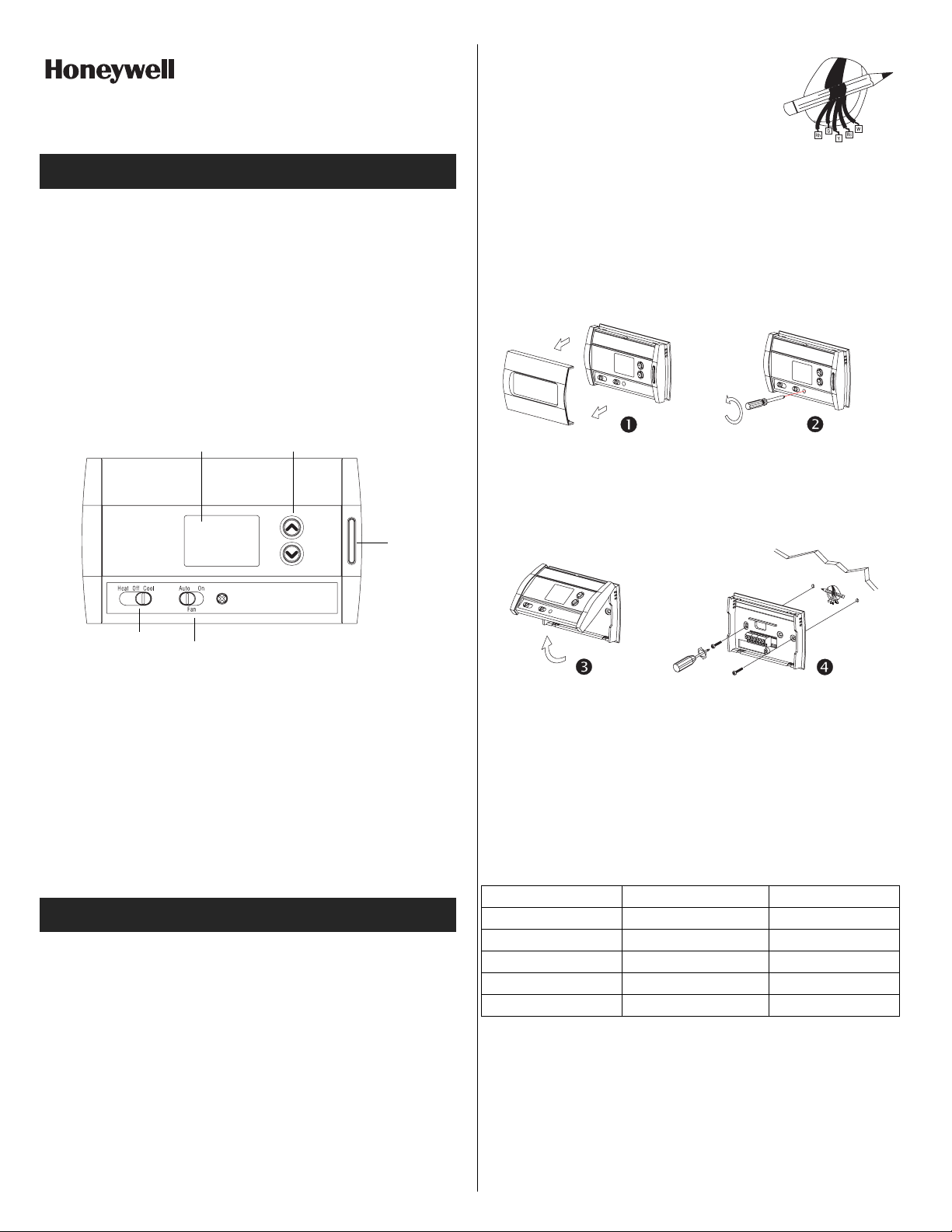
Adjustment
Display
buttons
Backlight
button
q Wrap the wires around a pencil to prevent
them from falling into the wall.
r If the hole in the wall is too big, insulate it
using a non-flammable material in order
to avoid air draughts behind the thermostat.
2.2 Installing the New Baseplate
For a new installation, choose a location approximately 5 feet
(1.5 m) above the floor and on an inside wall. Avoid draughty
areas (top of staircase, air outlet, etc.), dead air spots (behind
doors), direct sunlight or areas near concealed pipes or chimneys.
n Remove the thermostat faceplate.
o Loosen the locking screw to separate the thermostat from its
baseplate (the screw cannot be completely removed).
System operating
mode selector
Features
• System operating mode selection: heat, cool or off
• Fan operating mode selection: automatic or on (continuous)
• Programmable heating and cooling cycle lengths: 10, 12, 15, 20
or 30 minutes
• Temperatur e di sp l ay in °F or °C
• Backlit display
• Battery replacement indicator
• Interchangeable faceplates (titanium, charcoal & taupe)
Fan operating
mode selector
2. Installation
2.1 Removing the Old Thermostat
IN ORDER TO AVOID ANY RISK OF ELECTRIC SHOCK, CUT
POWER TO THE HEATING SYSTEM.
n Remove the old thermostat to access the wires.
Attention: If the old thermostat was mounted onto an electrical box,
it was probably powered by 120/240 volts. In this case, this thermostat cannot be used.
o Identify and label each wire (with the corresponding letter on
the wire terminal) and remove them from the terminals.
p If necessary, strip the end of each wire (maximum of 1/4 inch).
p Tilt the thermostat upwards.
q Mark and bore the appropriate mounting holes (using a 3/16”
drill bit) or use the existing holes. Insert the plastic anchors.
r Pass the wires through the opening of the baseplate and fix the
baseplate to the wall using the screws provided.
2.3 Connecting the Thermostat
Refer to the following table for matching the wire labels with the
thermostat terminals.
RTH2520 terminals Description Wire labels
Rh Heating power supply Rh, R, 4, V
Rc Cooling power supply Rc, R
W Heating signal W, W1, H
Y Cooling signal Y, Y1, M
GFan G, F
Note: Do not connect wires identified as C, X or B. Wrap the bare
end of these wires with electrical tape.
Important: The red jumper wire between Rh and Rc terminals must
be removed in a 5-wire installation.
RTH1120 69-1875EF 22/2/06 1/4
Page 2
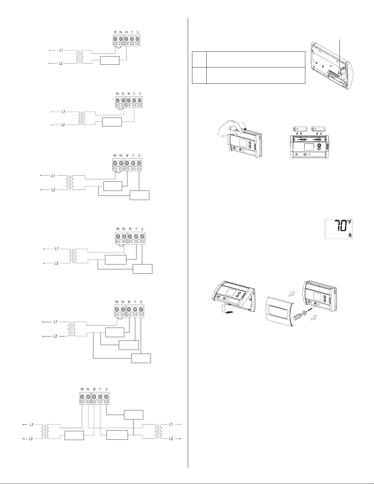
2.3.1 2-wire Heating
2.3.2 2-wire Cooling
2.3.3 3-wire Heating
2.3.4 3-wire Cooling
Heat relay
Cool relay
Heat relay
Cool relay
Fan relay
Fan relay
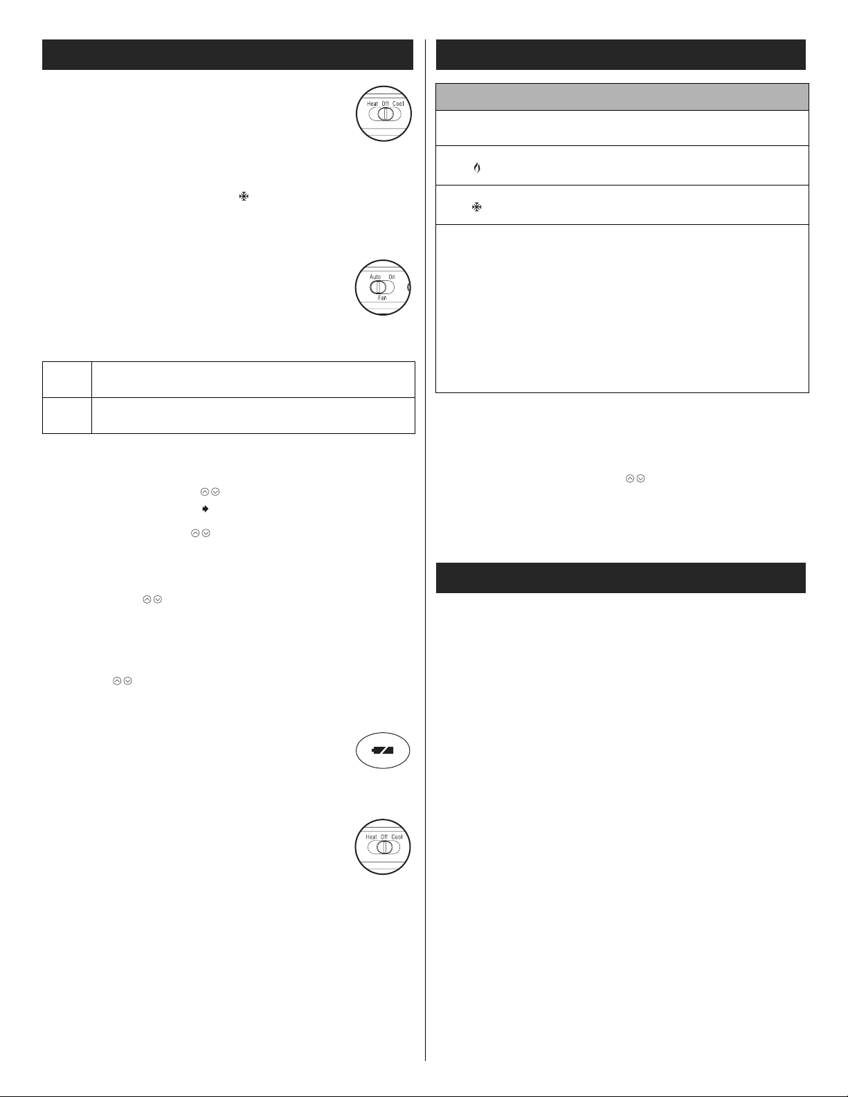
2.4 Setting J2 Jumper
The jumper specifies how the fan will operate
when it is placed in automatic mode (see section 3.2).
Leave the jumper in this position if you
HG
have a gas or oil heating system.
Move the jumper to this position if you
HE
have an electric heating system.
JP2 jumper
2.5 Installing the Batteries
n Pull out the battery cover.
o Install the batteries as shown. Observe the polarity.
p Reinstall the battery cover. You will hear a clicking sound.
After the batteries are installed, the thermostat performs a series of
tests for approximately 5 seconds.
Afterwards, the screen displays the actual temperature. It is normal that the displayed temperature will
be higher than the ambient temperature if you hold
the thermostat in your hands. It will display the
ambient temperature after the thermostat is
installed on the wall. By default, the setpoint is 70°F (21°C).
2.6 Completing the Installation
2.3.5 4-wire Heating and Cooling
Heat relay
Cool relay
Fan relay
2.3.6 5-wire Heating and Cooling
Fan relay
Heat relay
Note: Remove the red jumper wire between terminals Rc and Rh.
Cool relay
n Once the baseplate and the batteries are installed, mount the
thermostat on the baseplate.
o Secure the thermostat using the locking screw and install the
faceplate.
p Apply power back to the system.
RTH1120 69-1875EF 22/2/06 2/4
Page 3
3. Basic Functions
3.1 System Operating Mode
Use the selector switch to place the system in Heating
mode (HEAT) or Cooling mode (COOL), or to turn the
system off.
Note: When you place the thermostat in Cooling mode, you might
need to wait up to five minutes before cooling can start. This is a
safety feature for the compressor. will flash on the screen until
cooling can start again.
3.2 Fan Operating Mode
Use the selector switch to set the fan to automatic
mode (AUTO) or continuous mode (ON).
Note: This switch is not used if you have a 2-wire
installation as the fan is not connected to the thermostat.
AUTO
3.3 Displaying the Temperature
The actual temperature is normally displayed. To view the setpoint,
press once on either of the buttons. The setpoint is displayed
for 5 seconds along with the icon.
Note: Pressing any of the buttons more than once will change
the setpoint.
The fan operates only when the heating or cooling system is On (typical setting).
The fan operates continuously. Use this setting to
ON
improve air circulation and air cleaning.
4. Configuration Menu
DISPLAY DESCRIPTION DEFAULT SETTINGS
Temperature
display
Heating cycles
per hour
Cooling cycles
per hour
1
When either the heating or cooling parameter is displayed, use
the system mode selector switch to alternate between the two
parameters.
2
For optimal heating control, use the setting that matches your
system as follows: 2=30 min (steam or gravity), 3=20 min (hot
water or 90%+ high-efficiency furnace),
4=15 min (gas or oil), 5=12 min (alternate setting for gas or oil),
6=10 min (electric).
3
The corresponding cooling cycle lengths are as follows: 2=30
min, 3=20 min, 4=15 min, 5=12 min, 6=10 min.
1
1
n To access the configuration menu, press the backlight button
for 3 seconds.
o To go to the next parameter (menu item), briefly press the back-
light button.
p To modify a parameter, press .
q Repeat steps 2 and 3 if necessary.
r Press the backlight button for 3 seconds to exit the configura-
tion menu.
°F °C or °F
4
4
2, 3, 4, 5 or 6
2, 3, 4, 5 or 6
2
3
3.4 Setting the Temperature
Press one of the buttons until the desired temperature is displayed.
3.5 Backlight
The display illuminates for 12 seconds when the backlight button or
either of the buttons is pressed.
3.6 Battery Replacement Indicator
An icon appears when the batteries need replacement.
This icon will flash for 120 days, then the the rmostat
will cut power to the heating/cooling unit. The icon disappears once the batteries are replaced. The temperature settings are saved and do not need to be re-entered.
Warning: Before removing the batteries, place the
system switch on the thermostat to Off. Otherwise, the
heating/cooling unit might still be running even after
the batteries are removed.
5. Technical Specifications
Power supply: 2 AA batteries
Maximum load: 1 A @ 24 Vac per output
Setpoint range (heating): 41 to 82°F (5 to 28°C)
Setpoint range (cooling): 59 to 95°F (15 to 35°C)
Display range: 23 to 122°F (-5 to 50°C)
Storage temperature: -2 to 122°F (-20 to 50°C)
Temperature display resolution: 1°F (0.5°C)
Accuracy: ± 1°F (0.5°C)
Heating/cooling cycle lengths: 10, 12, 15, 20 or 30 minutes (pro-
grammable)
Compressor short-cycle protection (minimum off time): 5 minutes
Data memory: non-volatile
Dimensions: 5 in. x 3 in. x 1 in. (127 mm x 75 mm x 28 mm)
RTH1120 69-1875EF 22/2/06 3/4
Printed in China
Page 4

6. Warranty
Honeywell warrants this product, excluding battery, to be free from
defects in the workmanship or materials, under normal use and service, for a period of one (1) year from the date of purchase by the
consumer. If at any time during the warranty period the product is
determined to be defective or malfunctions, Honeywell shal l repair
or replace it (at Honeywell's option).
If the product is defective,
(i) return it, with a bill of sale or o ther dated proof of purchase, to
the place from which you purchased it, or
(ii) call Honeywell Customer Care at 1-800-46 8-1502. Customer
Care will make the determination whether the product should
be returned to the following address: Honeywell Return Goods,
Dock 4 MN10-3860, 1885 Douglas Dr N, Golden Valley, MN
55422, or whether a replacement product can be sent to you.
This warranty does not cover removal or reinstallation costs. This
warranty shall not apply if it is shown by Honeywell that the defect or
malfunction was caused by damage which occurred while the product was in the possession of a consumer.
Honeywell's sole responsibility shall be to repair or replace the product within the terms stated above. HONEYWELL SHALL NOT BE
LIABLE FOR ANY LOSS OR DAMAGE OF ANY KIND, INCLUDING ANY INCIDENTAL OR CONSEQUENTIAL DAMAGES
RESULTING, DIRECTLY OR INDIRECTLY, FROM ANY BREACH
OF ANY WARRANTY, EXPRESS OR IMPLIED, OR ANY OTHER
FAILURE OF THIS PRODUCT. Some states do not allow the exclusion or limitation of incidental or consequential damages, so this limitation may not apply to you.
THIS WARRANTY IS THE ONLY EXPRESS WARRANTY HONEYWELL MAKES ON THIS PRODUCT. THE DURATION OF ANY
IMPLIED WARRANTIES, INCLUDING THE WARRANTIES OF
MERCHANTABILITY AND FITNESS FOR A PARTICULAR PURPOSE, IS HEREBY LIMITED TO THE ONE-YEAR DURATION OF
THIS WARRANTY. Some states do not allow limitations on how
long an implied warranty lasts, so the above limitation may not apply
to you.
This warranty gives you specific legal rights, and you may have
other rights which vary from state to state.
If you have any questions concerning this warranty, please write
Honeywell Customer Relations, 1985 Douglas Dr, Golden Valley,
MN 55422 or call 1-800-468-1502. In Canada, write Retail Products
ON15-02H, Honeywell Limited/Honeywell Limitée, 35 Dynamic
Drive, Scarborough, Ontario M1V4Z9.
7. Customer Assistance
If you have any questions about the operation of your thermostat,
please go to http://yourhome.honeywell.com, or call Honeywell
Customer Care toll-free at 1-800-468-1502.
RTH1120 69-1875EF 22/2/06 4/4
Page 5

RTH1120
Thermostat électronique non programmable
Guide d'installation et mode d'emploi
1. Introduction
Le thermostat non-programmable RTH110B peut servir à commander les appareils suivants :
• système de chauffage au gaz, au mazout ou à l'électricité - 2 ou
3 fils
• climatiseur central - 2 ou 3 fils
• système de chauffage à eau chaude avec ou sans pompe - 2 fils
• système millivolt - 2 fils
• système de chauffage et de climatisation central - 4 ou 5 fils
Remarque : Le thermostat n'est pas compatible avec les thermopompes ou
les systèmes multi-étages.
p Au besoin, dénuder l'extrémité de chacun des fils (maximum d e
6 mm).
q Enrouler les fils autour d'un crayon pour
les empêcher de glisser dans le mur.
r Si l'ouverture dans le mur est trop grande,
l'isoler au moyen d'un matériau
ininflammable pour éviter tout courant
d'air derrière le thermostat.
2.2 Installer la base du thermostat
S'il s'agit d'une nouvelle installation, choisir un emplacement à
environ 1,5 m (5 pi) du sol, sur un mur intérieur. Éviter les
courants d'air (haut d'un escalier, prises d'air , etc.), les endroits
où l'air est stagnant (derrière les portes), les rayons du soleil
ou les murs derrière lesquels passent des canalisations ou des
cheminées dissimulés.
Affichage
Sélecteur du mode
de fonctionnement
du système
Caractéristiques
• Sélection du mode de fonctionnement du système : chauffage,
climatisation ou arrêt
• Sélection du mode de fonctionnement du ventilateur :
automatique ou continu
• Programmation de la durée du cycle de chauffage ou de
climatisation : 10, 12, 15, 20 ou 30 minutes
• Affichage de la température en °F ou °C
• Écran rétroéclairé
• Indicateur de remplacement des piles
• Plaques frontales colorées (titanium, charbon et taupe)
Sélecteur du mode
de fonctionnement
du ventilateur
Boutons
de réglage
Bouton de
rétroéclairage
2. Installation
n Retirer la plaque frontale du thermostat.
o Dévisser la vis de fixation pour séparer le thermostat de sa
base (il est impossible de retirer entièrement cette vis).
p Soulever le thermostat vers le haut.
q Marquer et percer des trous de fixation (employer un foret de
3/16 po) ou utiliser les trous existants. Insérer les chevilles
d'ancrage.
q Marquer et aléser les trous de fixation appropriés (ou employer
les trous existants). Insérer les ancres en plastique.
r Passer les fils par l'ouverture dans la base et fixer la base au
mur au moyen des vis fournies.
2.3 Raccorder le thermostat
Se référer au tableau suivant afin d’identifier le fil correspondant à
chaque borne du thermostat.
2.1 Retirer l'ancien thermostat.
POUR ÉVITER TOUT RISQUE DE CHOC ÉLECTRIQUE,
COUPER L'ALIMENTATION DU SYSTÈME DE CHAUFFAGE.
n Retirer l'ancien thermostat pour accéder aux fils.
Mise en garde : Si l'ancien thermostat était installé sur une boîte
électrique, il était probablement alimenté par du courant à 120/240
volts. Dans ce cas, le nouveau thermostat ne convient pas.
o Identifier et étiqueter chaque fil (avec la lettre de la borne
correspondante) et débrancher les fils des bornes.
RTH1120 69-1875EF 22/2/06 1/4
Bornes du RTH1120 Description Identification du fil
Rh Alimentation - chauffage Rh, R, 4, V
Rc Alimentation - climatisation Rc, R
W Signal - chauffage W, W1, H
Y Signal - climatisation Y, Y1, M
G Ventilateur G, F
Remarque : Ne pas brancher les fils identifiés comme C, X ou B.
Couvrir le bout dénudé de ces fils avec du ruban électrique.
Important : L e cavalier (fils rouge) entre les bornes Rc et Rh doit
être enlevé dans une installation à 5 fils.
Page 6

2.3.1 Chauffage, 2 fils
2.4 Réglage du cavalier J2
Le cavalier sert à spécifier le
fonctionnement du ventilateur en mode
automatique (voir la section 3.2).
Cavalier J2
Relais
chauffage
2.3.2 Climatisation, 2 fils
Relais
climatisation
2.3.3 Chauffage, 3 fils
Relais
chauffage
2.3.4 Climatisation, 3 fils
Relais
climatisation
2.3.5 Chauffage et climatisation, 4 fils
Relais
ventilateur
Relais
ventilateur
Laisser le cavalier dans cette position
HG
s’il s’agit d’un système de chauffage à
gaz ou au mazout.
Placer le cavalier dans cette position
HE
s’il s’agit d’un système de chauffage
électrique.
2.5 Installer les piles
n Enlever le couvercle du compartiment à piles.
o Installer les piles comme sur l'illustration. Observer la polarité.
p Remettre le couvercle en place. Un déclic se fera entendre.
Une fois les piles installées, le thermostat effectue une série de
tests, qui dure environ 5 secondes.
Ensuite, l'écran affiche la température mesurée. Il
est normal que la température affichée soit
supérieure à la température ambiante si le
thermostat est dans vos mains. Le thermostat
affichera la température ambiante lorsqu'il sera installé au mur. Par
défaut, la température réglée est à 70 °F (21 °C).
2.6 Terminer l'installation
Relais
chauffage
Relais
climatisation
2.3.6 Chauffage et climatisation, 5 fils
Relais
ventilateur
n Une fois la base et les piles installées, fixer le thermostat sur la
base.
o Visser le thermostat au moyen de la vis de fixation et inst aller la
plaque frontale.
p Rétablir l'alimentation électrique du système.
Relais
ventilateur
Relais
chauffage
Remarque : Enlever le cavalier (fil rouge) entre les bornes Rc et
Rh.
RTH1120 69-1875EF 22/2/06 2/4
Relais
climatisation
Page 7

3. Fonctions de base
3.1 Mode de fonctionnement du système
Utiliser le sélecteur pour placer le système en mode
chauffage (Heat) ou en mode climatisation (Cool), ou
en arrêt (Off).
Remarque : Lorsqu’on place le thermostat en mode climatisation, il
peut y avoir jusqu'à cinq minutes d’attente avant que la climatisation
soit activée. Ceci est une protection pour le compresseur. L’icône
clignotera durant le délai.
3.2 Mode de fonctionnement du ventilateur
Utiliser le sélecteur pour placer le ventilateur en mode
automatique (AUTO) ou en mode continu (ON).
Remarque : Ce sélecteur n'est pas utilisé dans les
installations à 2 fils puisque le ventilateur n'est pas
relié au thermostat.
AUTO
3.3 Afficher la température
La température mesurée est normalement affichée. Pour voir la
température réglée, appuyer sur un des boutons . Celle-ci
s'affichera pendant 5 secondes, accompagnée de l'icône .
Remarque : Si l'on appuie sur un bouton plus d'une fois, la tempé-
rature réglée sera modifiée.
3.4 Régler la température
Appuyer sur l'un des boutons jusqu'à ce que la température
désirée soit affichée.
3.5 Retroéclairage
L’écran s’illumine pendant 12 secondes lorsqu’on appuie sur le bouton de rétroéclairage ou l’un des boutons .
3.6 Indicateur de remplacement des piles
Une icône apparaît à l'écran lorsqu'il faut remplacer
les piles. Cette icône clignotera pendant 120 jours,
puis le thermostat coupera l'alimentation au système.
L'icône disparaît une fois les piles remplacées.
Les réglages de température sont toutefois sauvegardés lorsque
les piles sont enlevées.
Avertissement : Avant d'enlever les piles, placer le
sélecteur du système sur le thermostat à Off. Sinon, le
système de chauffage/climatisation pourrait encore
fonctionner même lorsque les piles sont enlevées.
Le ventilateur fonctionne seulement lorsque le chauffage
ou la climatisation est activée (réglage typique).
Le ventilateur fonctionne continuellement. Utiliser ce
ON
réglage pour améliorer la circulation et la purification de
l’air.
4. Menu de configuration
1
PAR
DÉFAUT
°F °C ou °F
4
4
RÉGLAGES
2, 3, 4, 5 ou 6
2, 3, 4, 5 ou 6
AFFICHAGE DESCRIPTION
Affichage de la
température
Nombre de cycles de
chauffage à l'heure
Nombre de cycles de
climatisation à l'heure
1
Lorsque le paramètre de chauffage ou celui de climatisation est
affiché, utiliser le sélecteur du mode de fonctionnement du système pour passer d'un paramètre à l'autre.
2
Pour une régulation optimale du chauffage, choisir le réglage qui
correspond à votre système : 2=30 min (vapeur, gravité), 3=20
min (eau chaude, 90%+ haute efficacité), 4=15 min (gaz ou
mazout), 5=12 min (gaz ou mazout), 6=10 min (électrique).
3
Les durées de cycle de climatisation correspondantes sont :
2 = 30 min, 3 = 20 min, 4 = 15 min, 5 = 12 min, 6 = 10 min.
n Pour accéder au menu de configuration, appuyer sur le bouton
de retroéclairage pendant 3 secondes.
o Pour passer au paramètre suivant du menu, appuyer
brièvement sur le bouton de retroéclairage.
p Pour modifier un paramètre, appuyer sur l'un des boutons .
q Répéter les étapes 2 et 3 au besoin.
r Appuyer sur le bouton de retroéclairage pendant 3 secondes
pour quitter le menu de configuration.
5. Fiche technique
Alimentation : 2 piles AA
Charge maximale : 1 A sous 24 V c.a. par sortie
Plage de réglage (chauffage) : 5 à 28 °C (41 à 82 °F)
Plage de réglage (climatisation) : 15 à 35 °C (59 à 95 °F)
Plage d'affichage : -5 à 50 °C (23 à 122 °F)
Température d'entreposage : -20 à 50 °C (-2 à 122 °F)
Résolution de l'affichage : 0,5 °C (1 °F)
Précision : ± 0,5 °C (1 °F)
Protection anti-court cycle du compresseur (temps d’arrêt minimal) :
5 minutes
Durée du cycle de chauffage/climatisation : 10, 12, 15, 20 ou 30
minutes (programmable)
Mémoire : non volatile
Encombrement : 127 mm x 75 mm x 28 mm (5 po x 3 po x 1 po)
2
3
RTH1120 69-1875EF 22/2/06 3/4
Imprimé en Chine
Page 8

6. Garantie
Honeywell garantit ce produit, à l'exception des piles, contre tout
vice de fabrication ou de matière dans la mesure où il en est fait une
utilisation et un entretien convenables, et ce, pour un (1) an à partir
de la date d'achat par le consommateur. En cas de défectuosité ou
de mauvais fonctionnement pendant la période de garantie,
Honeywell remplacera ou réparera le produit (au gré de Honeywell).
Si le produit est défectueux,
(i) le retourner, accompagné d'une preuve d'achat indiquant la
date d'achat, à l’endroit où il a été acheté, ou
(ii) s'adresser au Service à la clientèle de Honeywell en
composant le 1-800-468-1502. Le Service à la clientèle
déterminera alors si le produit doit être retourné à l'adresse
suivante : Honeywell Return Goods, Dock 4 MN10-3860, 1885
Douglas Dr N, Golden Valley, MN 55422, ou si un produit de
remplacement peut vous être expédié.
La présente garantie ne couvre pas les frais de retrait ou de
réinstallation. La présente garantie ne s'appliquera pas s'il est
démontré que la défectuosité ou le mauvais fonctionnement est dû
à un endommagement du produit alors que le consommateur l'avait
en sa possession.
La responsabilité de Honeywell se limite à réparer ou à remplacer le
produit conformément aux modalités susmentionnées.
HONEYWELL N'EST EN AUCUN CAS RESPONSABLE DES
PERTES OU DOMMAGES, Y COMPRIS LES DOMMAGES
INDIRECTS OU ACCESSOIRES DÉCOULANT DIRECTEMENT
OU INDIRECTEMENT D'UNE VIOLATION QUELCONQUE D'UNE
GARANTIE, EXPRESSE OU T ACITE, APPLICABLE AU PRÉSENT
PRODUIT NI DE TOUTE AUTRE DÉFECTUOSITÉ DU PRÉSENT
PRODUIT. Certaines provinces ne permettent pas l'exclusion ou la
restriction des dommages indirects et, par conséquent, la présente
restriction peut ne pas s'appliquer.
LA PRÉSENTE GARANTIE TIENT LIEU DE TOUTES LES
AUTRES GARANTIES, EXPRESSES OU TACITES, ET LES
GARANTIES DE VALEUR MARCHANDE ET DE CONFORMITÉ À
UNE FIN PARTICULIÈRE SONT PAR LES PRÉSENTES
EXCLUES APRÈS LA PÉRIODE DE UN AN DE LA PRÉSENTE
GARANTIE Certaines provinces ne permettent pas de limiter la
durée des garanties tacites et, par conséquent, la présente
limitation peut ne pas s'appliquer.
La présente garantie donne au consommateur des droits légaux
spécifiques et peut-être certains autres droits qui peuvent varier
d'une province à l'autre.
Pour toute question concernant la présente garantie, p rière d'écrire
au Service à la clientèle de Honeywell à l'adresse suivante :
Honeywell Customer Relations, 1985 Douglas Drive, Golden Valley ,
MN 55422, ou encore composer le 1-800-468-1502. Au Canada,
prière de s'adresser au service des Produits de détail, Honeywell
Limited/Honeywell Limitée, 35, Dynamic Drive, Scarborough
(Ontario) M1V 4Z9.
7. Service à la clientèle
Si vous avez des questions sur le fonctionnement de votre
thermostat, veuillez consulter http://yourhome.honeywell.com, ou
vous adresser au Service à la clientèle de Honeywell en composant
sans frais le 1-800-468-1502.
RTH1120 69-1875EF 22/2/06 4/4
 Loading...