

Honeywell RS-485 Installation Manual

Honeywell Process Solutions
RS-485 Adapter Board
Installation Guide
November 2010
Revision B
Honeywell
Installation Guide
Metretek
RS-485 Adaptor Board
2
www.honeywell.com

Introduction:
Most persons that work with computers and/or communications equipment are at least
somewhat familiar with the terms RS-232, USB, Fire-wire, and LAN to name a few.
RS-485 is less commonly known however, but serves well in applications where high
data rates, excellent noise immunity, and long cable runs are necessary. As is often the
case, there are both advantages and downsides to RS-485 when compared against other
systems. It is the purpose of this manual to help develop a basic understanding of the
RS-485 data transfer system, as well as providing specific details related to installation of
the RS-485 adaptor board.
Overview of RS-232:
RS-232 (also known as V.24) is a relatively aged serial data transfer topology (1969), but
still finds wide acceptance due to the large installed base, simplicity, and proven
performance. Initially introduced with a 25-pin D-Sub style connector, the 9-pin variety
is far more common at the present. Serial data is transferred over TXD and RXD lines
with respect to a signal common. Transition levels are specified at a maximum of +15
volts to a minimum of -15 volts, although in practice it is more common to find swings in
the range of approximately +8 to -8 volt levels. Data is transferred as a series of high and
low signal levels, using a serial data transfer protocol with start bits, data bits, stop bits,
and parity. A typical setting might be 1 start bit, 8 data bits, 1 stop bit, and no parity to
transfer a single byte (8-bits) of useful information.
Maximum practical data transfer rate is 19.2k bits per second (bps), with cable lengths at
50 feet, and several times faster with shorter cable runs. It is only possible to have a
single pair of devices connected; multi-drop capability does not exist. Immunity to
electrical noise is rather poor when operating in harsh environments such as factory floor
sites, traffic light controllers, refineries, etc.
Overview of RS-485:
As previously alluded to, RS-232 has some definite limitations for applications requiring
longer cable runs and higher data transfer rates. RS-485 (EIA-485 standard) uses
balanced transmission lines (differential signaling) to transfer serial data bytes. This
method has inherently higher noise immunity, thereby permitting high data rates and long
cable runs. Theoretical data transfer rates are on the order of 10M bps and 1200m
(approx. 4000 ft) cable length, although it is often necessary to scale back the speed at
such extreme lengths.
In the case of the RS-485 adaptor board coupled with the CNI, the limiting factor is the
CNI board itself, which only supports data transfers up to 38,400 bps. Taking into
consideration the intended applications for the CNI product, higher data transfer rates are
not relevant, and it is the potential long cable runs that are beneficial.
RS-485 specifications state that ‘multi-drops’ are supported for additional transmitters and
receivers sharing the same cable. Receiver impedance is specified to be 12k ohms for a
single unit load. Given this impedance, up to 32 unit loads can be supported on the bus.
3

Receivers with a higher input impedance will have a fractional unit load value assigned,
since the circuit loading effect is correspondingly less.
To obtain optimal performance with long cable runs and high data rates, it is necessary to
carefully select the cable type that is to be used. A typical cable will have twisted pairs of
24awg. wires, be fully shielded, and have a nominal impedance of 120 ohms. Alpha Wire
Company type 5473C, or equivalent is suitable for most applications. Additional
recommendations for wiring practices are detailed in a later section of this document.
While it is beyond the scope of this document to elaborate on transmission line theory, it
is not beyond the scope of the field installed device to demand proper termination of the
signal line. Long cable runs and high data rates will require that a 120 ohm termination
resistor is at the end of the cable, near the last receiver. This prevents reflections from
occurring at the end of the cable, resulting in signal distortion. Referring again to the
CNI product, leisurely data transfer rates of 38.4k bps (or slower) do not require
as much concern about termination resistors. As a matter of practice, it is still a good idea
however, and the RS-485 board can have the 120 ohm termination added by
simply placing a jumper on JP1.
RS-485 differential signaling levels are specified to not exceed a ±6 volt swing for an
unloaded transmitter, and the receiver sensitivity must be at least ±0.200 volts. Since it is
possible to have multiple transmitters on a bus, the data transmission protocol must
ensure that ‘line contention’ events do not take place. Specifics of signaling protocols and
data transmission are not defined within the framework of the EIA-485 standard
however; only the physical interface is detailed.
If the preceding description appears to suggest that the installer must possess an
Engineering degree to understand and setup a system, then it must be admitted that this
feeling is at least partially justified. If the goal was to operate at maximum transfer rates
with lengthy cable runs, and numerous nodes, then it is true that the installation is likely
to be a bit of a challenge. Fortunately enough, most applications for the CNI /
RS-485 combination are relatively straightforward, and the following guidelines are
intended to make the process as simple as possible.
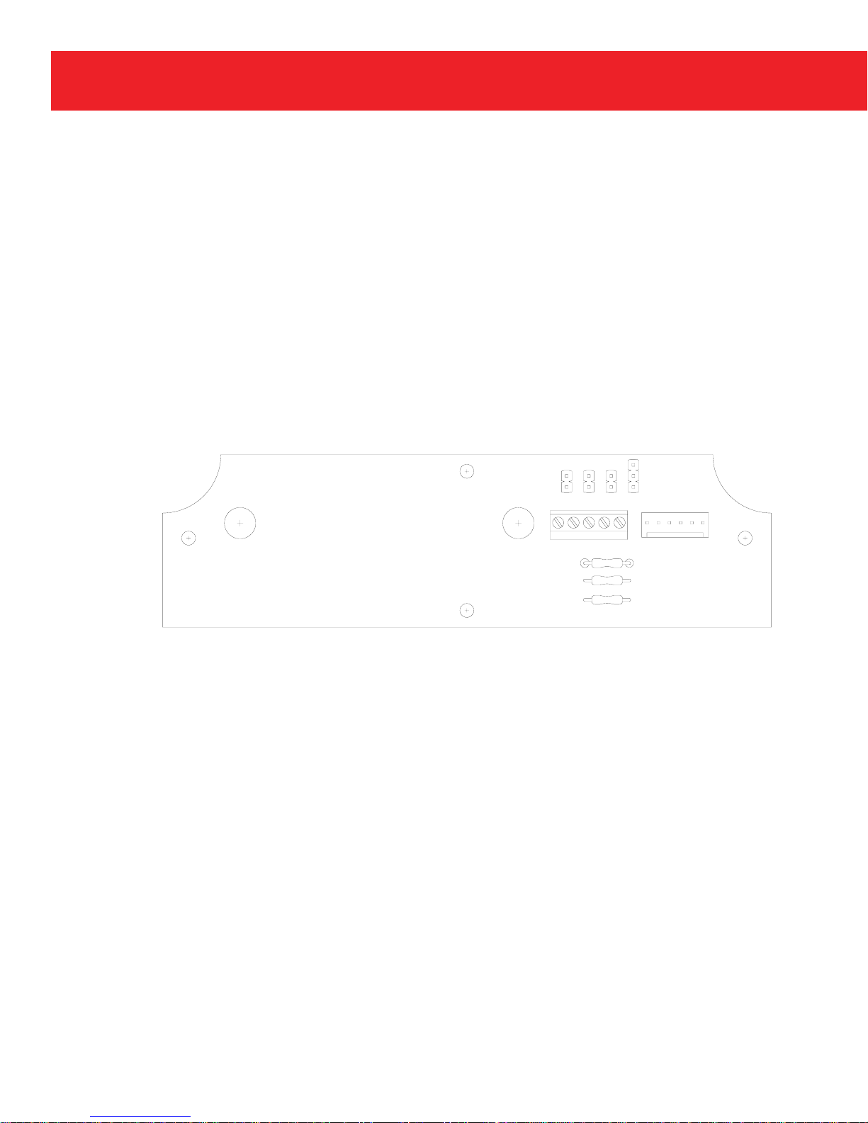
RS-485 Board Installation:
If the RS-485 adaptor board is not already installed into the enclosure, then Figures 1 & 2
should be referenced for assembly. Two small #4 size self-threading type screws and a
cable assembly will have been included with each kit.
4
www.honeywell.com
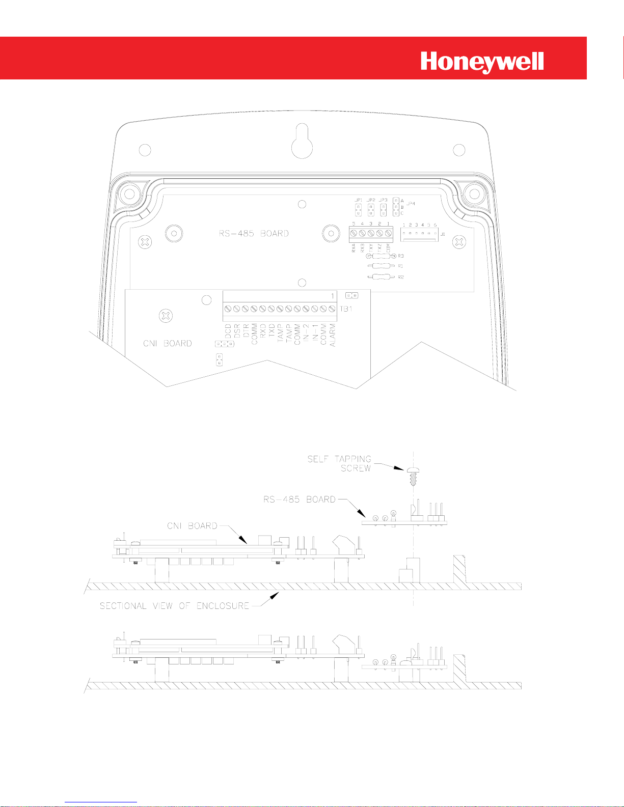
Figure-1
RS-485 Board Mounting Position
Figure-2
Securing the RS-485 Board
5
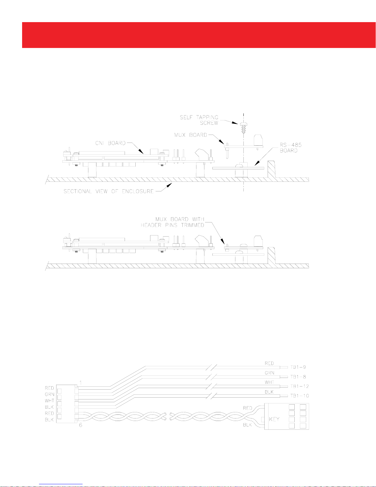
In some cases it may be desirable to install a serial port multiplexer board (Mux) into the
system as well. Detailed information regarding the CNI and Mux board can be found in
the relevant owners manual for these items. It should be mentioned however that it may
be necessary to trim-off the header pins from the Mux board, if this was not previously
done. Access to the header pins is not required, and in fact would pose a mechanical
assembly conflict if left intact as seen in Figure-3.
Figure-3
Optional RS-232 Multiplexer Board
Electrical connections to the CNI board are of course required, and a cable has been
provided for this purpose as illustrated in Figure-4. The six position connector shown at
the left of Figure-4 attaches to J1 of the RS-485 board. The rectangular power connector
(R.H. side of drawing) connects to J3 on the CNI board. Remaining are the four
individual wires that must be attached to the CNI terminal block. Terminal block
positions are indicated for reference.
Figure-4
Cable Assembly, RS-485 Board to CNI Board
6
www.honeywell.com
 Loading...