

Honeywell R7795A, R7795D, R7795B, R7795C Users Manual

Primary Controls
The R7795 Flame Safeguard Primary Control
provides flameout protection plus automatic
control of commercial and industrial gas and
oil burners. Models provide intermittent pilot
or interrupted pilot with delayed main valve.
R7795A,B,C,D
Flame Safeguard
■ Integral solid state color-coded flame amplifiers:
R7795A,C for ultraviolet detection systems (purple).
R795B,D for rectification detection systems (green).
See Table 1.
■ Solid state plug-in ST95A Purge Timers provide
prepurge timings of 1.5, 7, 10, 30, 60, or 90 seconds.
■ Includes terminals for connection of a line voltage
airflow switch to prove airflow from the start of
prepurge through the run period.
■ Mounts on a Q795A Subbase with two captive
screws. All electrical connections are automatically
provided between the device and subbase. Wiring
terminals are accessible for testing.
■ Meter jack on amplifier board for measuring flame
signal with system in operation.
■ Internal light-emitting diode (LED) indicates pres-
ence of flame signal.
■ Field selectable ten or four second trial for pilot
flame ignition.
■ Powered alarm terminal to operate an external line
voltage alarm on safety lockout.
■ R7795 models are available with either intermittent
pilot (interrupted ignition) or interrupted pilot and
delayed main valve. See Table 2.
■ Run-Test switch on interrupted pilot/delayed main
valve models.
■ Safe-start feature prevents start-up with lockout if
flame or a flame simulating failure exists.
■ Recycle or lockout on flame failure is field selectable.
■ Safety switch must be manually reset after lockout.
■ Meets Underwriters Laboratories, Canadian Stan-
dards Association, and Factory Mutual Approved
standards.
CONTENTS
Specifications ................................................. 2
Ordering Information.....................................2
Detailed Operating Sequence ........................4
Installation ..................................................... 8
Checkout....................................................... 11
Troubleshooting ........................................... 17
Service ..........................................................19
1 66-2001—2 B. M. • Rev. 9-93 • ©Honeywell Inc. 1993 • Form Number 66-2001—2
R7795A,B,C,D
SPECIFICATIONS • ORDERING INFORMATION
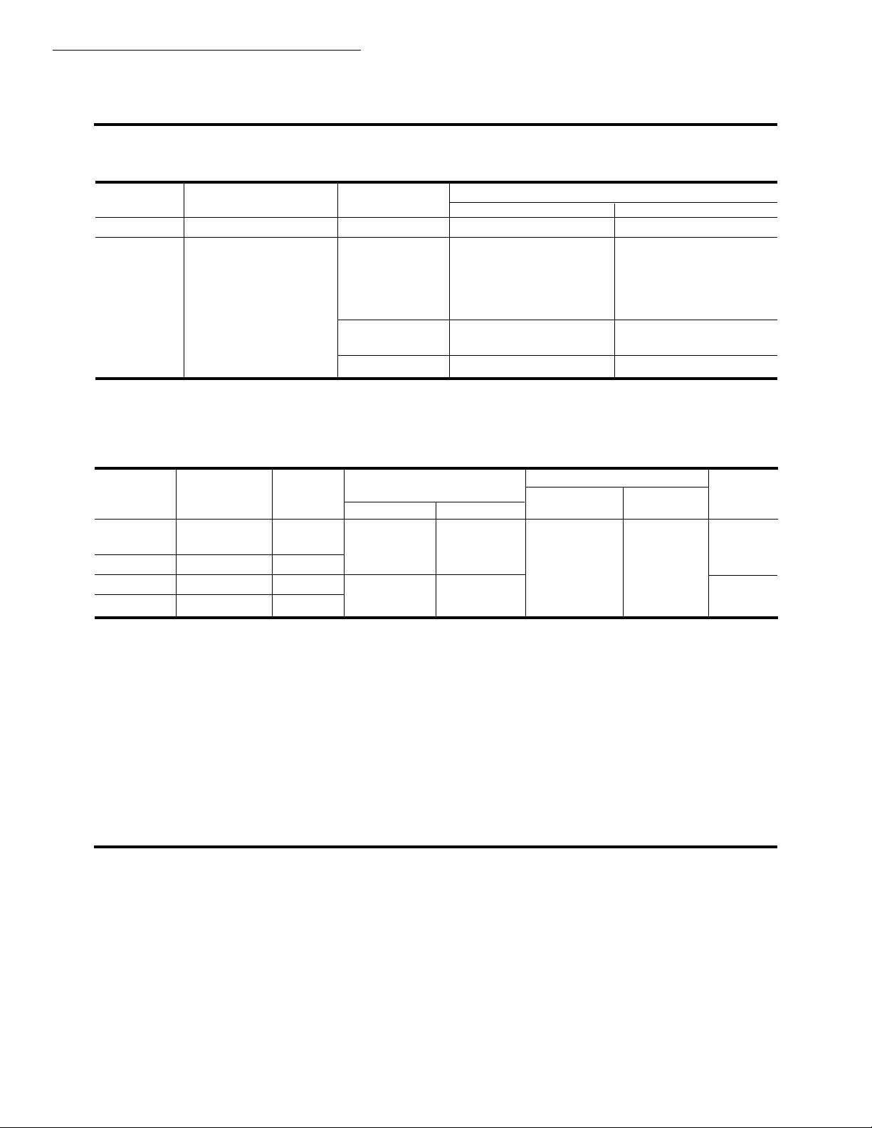
TABLE 1—FLAME DETECTION SYSTEMS.
Flame Detection Applicable Flame Detectors
Model Amplifier Type Fuel Type Models
R7795A,C Ultraviolet (purple) Gas, oil UV (Minipeeper) C7027, C7035, C7044
R7795B,D Rectification (Green) Gas Rectifying flame rods Holders:a C7004,
a
Order flame rod separately.
b
Use Honeywell part no. 38316 Photocell only.
Specifications
C7007, C7011
Complete Assy:
C7005, C7008,
C7009, Q179
Oil Rectifying photo cellsbC7003, C7010,
C7013, C7014
Gas, oil, coal UV (Purple Peeper) C7012A,C
TABLE 2—R7795 MODELS AVAILABLE.
Flame Flame Establishing Flame Failure
Detection Amplifier Period (sec) Nominal Device Run/Test
R7795 Type Color Pilot
R7795A UV Purple Intermittent Intermittent 3 Recycle No
R7795B Rectification Green
R7795C UV Purple 10/4 10 Yes
R7795D Rectification Green Interrupted Seconds
a
Field selectable:
10 sec with the orange jumper wire unclipped.
4 sec with the orange jumper wire clipped.
b
Field selectable:
Recycle with the yellow jumper wire unclipped.
Lockout with the yellow jumper wire clipped.
a
Main Response (sec) Reaction
Pilot or Lockout
b
Switch
Ordering Information
When purchasing replacement and modernization products from your TRADELINE® wholesaler or your distributor, refer to the
TRADELINE Catalog or price sheets for complete ordering number, or specify—
1. Order number, TRADELINE, if desired.
If you have additional questions, need further information, or would like to comment on our products or services, please write or
phone:
1. Your local Honeywell Home and Building Control Sales Office (check white pages of phone directory).
2. Home and Building Control Customer Satisfaction
Honeywell Inc., 1885 Douglas Drive North
Minneapolis, Minnesota 55422-4386 (612) 951-1000
In Canada—Honeywell Limited/Honeywell Limitée, 740 Ellesmere Road, Scarborough, Ontario M1P 2V9. International
Sales and Service Offices in all principal cities of the world. Manufacturing in Australia, Canada, Finland, France, Germany,
Japan, Mexico, Netherlands, Spain, Taiwan, United Kingdom, U.S.A.
2
R7795A,B,C,D
SPECIFICATIONS
ELECTRICAL RATINGS:
Voltage and Frequency: 120 Vac, (+10, -15%), 50/60 Hz.
Power Consumption:
R7795A,C: 17 VA (maximum).
R7795B,D: 15 VA (maximum).
TERMINAL RATINGS:
Maximum Rating
Terminal Load at 120 Vac
5Pilot Valve 125 VA pilot duty.
18 Ignition 360 VA.
6, 7 Main Fuel 125 VA pilot duty or
Valve(s) 25 VA pilot duty plus
one or more motorized
valves with a total rating
of 500 VA opening,
250 VA holding.
8 Fan or 9.8A full load; 58.8A
burner motor locked rotor.
9Alarm 1.0A.
NOTE: Allowable inrush can be up to ten times the pilot
duty rating.
Example:
Pilot duty rating = 125 VA. At 120V, running current is
125/120 = 1.05A.
Maximum allowable inrush is 10 times 1.05 = 10.5A.
AMBIENT TEMPERATURE RANGES:
Operating: -40° F [-40° C] to +135° F [+57° C].
FLAME FAILURE RESPONSE: 3 seconds nominal.
DIMENSIONS: Approximately 5 x 5 x 5-1/4 in. [127 x 127
x 133.5 mm].
WEIGHT: 2.0 lb [0.9 kg].
MOUNTING: Two captive screws in device for mounting
onto Q795A Subbase (ordered separately).
APPROVALS:
Underwriters Laboratories Inc. listed: File No. MP268,
Guide No. MCCZ.
Canadian Standards Association certification: pending.
Factory Mutual approved: Report No. J.I. OR4A2.AF
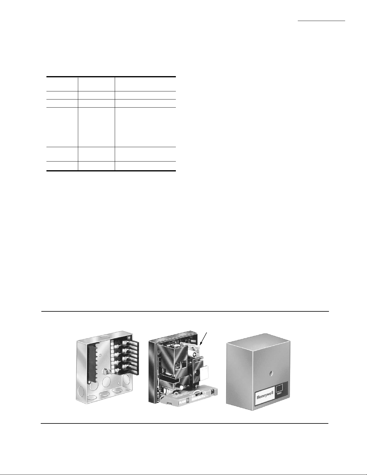
ACCESSORIES (See Fig. 1):
W136A Test Meter (includes 196146 Meter Connector
Plug).
196146 Meter Connector Plug for older W136A Test
Meters.
123514A Flame Simulator for rectification systems.
123514B Flame Simulator for ultraviolet systems.
Q624A Solid State Spark Generator.
Q795A Wiring Subbase.
ST795A Plug-in Purge Timer (models available with
1.5, 7, 10, 30, 60, and 90 second timings).
FSP5004A with adapter for operational check of the
R7795.
R1061012 Ignition Cable for ignition installations in
high temperature environments; rated at 350° F
[177° C] for continuous duty, and up to 500° F
[260° C] for intermittent use; tested to 20,000 Vrms.
R1239001 High Tension Ignition Cable for ignition
installations in a contaminating environment; very
resistant to severe conditions of oil, heat, and corona.
Tested to withstand high voltages up to 25,000 Vrms
in a salt bath for one minute without breakdown.
Rated at 200° F [93° C] for continuous duty, and up
to 250° F [177° C] for intermittent use.
R1298020 Cable for flame detector (F leadwire) instal-
lations in a high temperature environment; rated up
to 400° F [204° C] for continuous duty; tested for
operation up to 600V and breakdown up to 7500V.
198365A Remote Reset Cover. Heavy duty cover with
remote reset assembly; 120 Vac, 50/60 Hz solenoid
will only fit R7795 with a series number of 1.
198365B Remote Reset Cover. Heavy duty cover with
remote reset assembly; 120 Vac, 50/60 Hz solenoid
will only fit R7795 with a series number of 2.
Fig. 1—R7795 System components.
Q795A WIRING SUBBASE COVER
ST795A
PREPURGE
TIMER
M12389
3 66-2001—2
R7795A,B,C,D
DETAILED OPERATING SEQUENCE
Detailed Operating Sequence
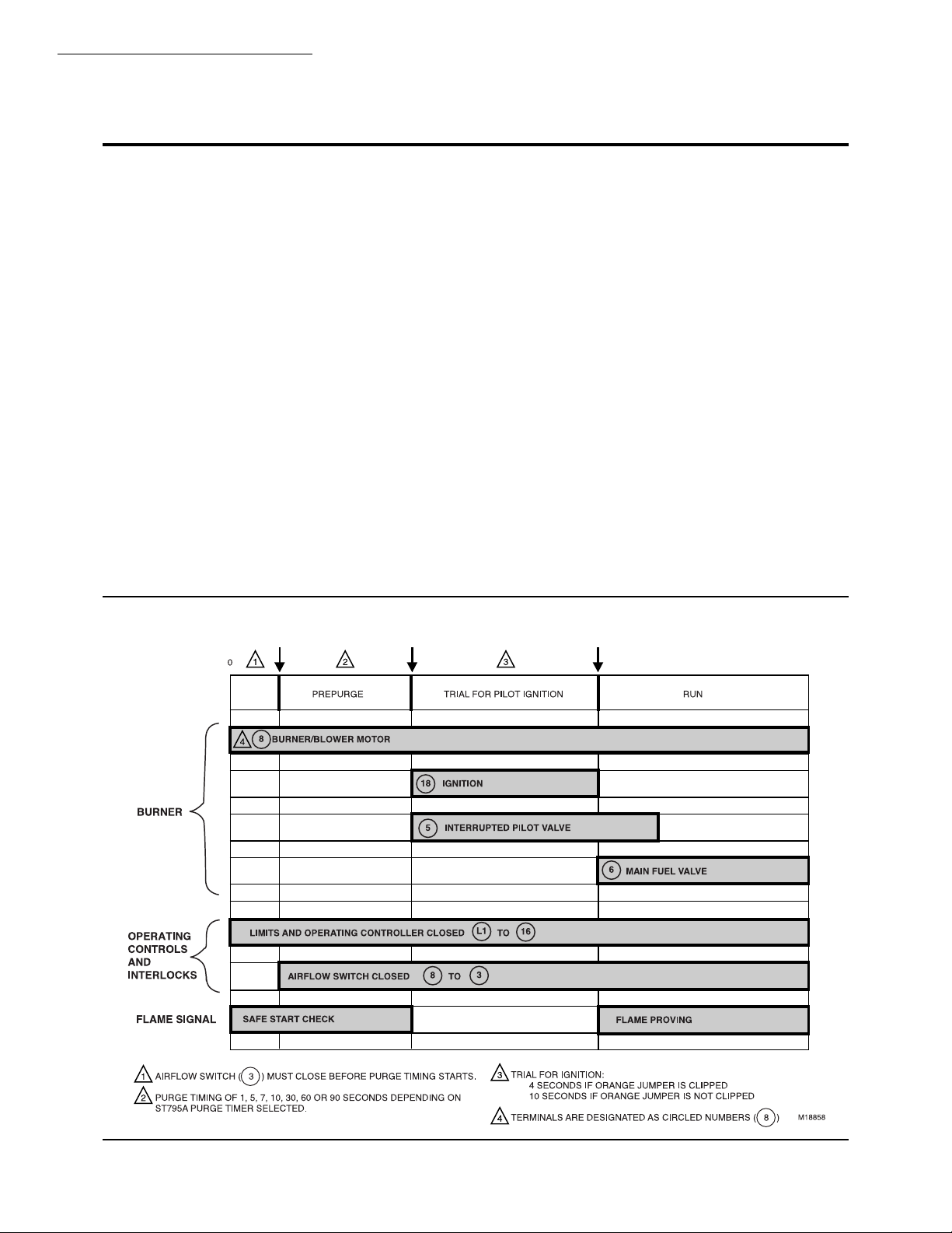
The R7795A,B provides the following operational sequence when used with the appropriate flame detector. (See
Figs. 2 and 3.)
STANDBY
The R7795 Primary Control is ready to start up when
the burner controller closes (limits are closed).
NORMAL START-UP
1. With power applied (limits and controller closed,
terminal L1 to 16, and no flame signal present) the 3K relay pulls in and the burner motor (terminal 8) is energized.
2. As soon as the airflow switch closes (terminal 3 to
8), the ST795A Prepurge Timer starts to time out (prepurge begins).
NOTE: The ST795A Prepurge Timer returns to zero any
time the airflow switch opens. The prepurge restarts
when the airflow switch recloses.
Fig. 2—Operating sequence for the R7795A,B, with intermittent pilot.
3. PILOT FLAME ESTABLISHING PERIOD.
At the end of prepurge (ST795A timed out), the 1K
relay pulls in, energizing the ignition transformer (terminal 18) and the intermittent pilot valve (terminal 5). This
starts the ten or four second pilot flame establishing
period. Safety shutdown and lockout will occur if presence of flame is not proven within:
•Ten seconds if the ORANGE jumper is not clipped.
• Four seconds if the ORANGE jumper is clipped.
4. MAIN FLAME IGNITION TRIAL
At the end of the pilot flame establishing period (ten or
four seconds), and with pilot flame present, the main valve
(terminal 6) is energized.
The R7795 is now in the normal burner run mode of
operation and will remain so until an external command
directs it to do otherwise.
5. NORMAL SHUTDOWN
When the burner controller opens, the pilot valve (terminal 5), the main valve (terminal 6) and the burner/
blower motor (terminal 8) are immediately de-energized.
The R7795 goes into the standby mode, terminating the
operating cycle.
4

Fig. 3—Internal schematic of the R7795A,B with intermittent pilot.
R7795A,B,C,D
DETAILED OPERATING SEQUENCE
BASIC DIAGRAM OF
THE R7795A
BURNER
MOTOR
LINE VOLTAGE
ALARM
LINE VOLTAGE
AIRFLOW SWITCH
CONTROLLER
LIMIT(S)
BASIC DIAGRAM OF
THE R7795B
5
7
2K1
3K3
8
16
S.SW
9
3
OPTO
ISOLATOR
ST795A
3K1
1K2
S.SW
F1
3K
FLAME AMPLIFIER
SOLID STATE
LOGIC CKT.
1K
2K
2K1
6
18
L1
L2
F
G
3
5
INTERRUPTED
PILOT VALVE
MAIN
FUEL VALVE
IGNITION
TRANSFORMER
2
FLAME
DETECTOR
L1
(HOT)
L2
INTERRUPTED
PILOT VALVE
1
120 Vac
60 HZ
BURNER
MOTOR
LINE VOLTAGE
ALARM
LINE VOLTAGE
AIRFLOW SWITCH
CONTROLLER
LIMIT(S)
POWER SUPPLY. PROVIDE DISCONNECT MEANS AND OVERLOAD
1
PROTECTION AS REQUIRED.
SELECT APPROPRIATE FLAME DETECTOR.
2
8
16
9
3
3K3
S.SW
ST795A
3K1
1K2
F1
S.SW
3K
FLAME AMPLIFIER
SOLID STATE
1K
LOGIC CKT.
2K
CONNECT TERMINAL TO EARTH GROUND.
3
G
2K1
2K1
7
6
18
L1
L2
F
G
3
MAIN
FUEL VALVE
IGNITION
TRANSFORMER
2
FLAME
DETECTOR
L1
(HOT)
L2
M11915
1
120 Vac
60 HZ
5 66-2001—2
R7795A,B,C,D
DETAILED OPERATING SEQUENCE
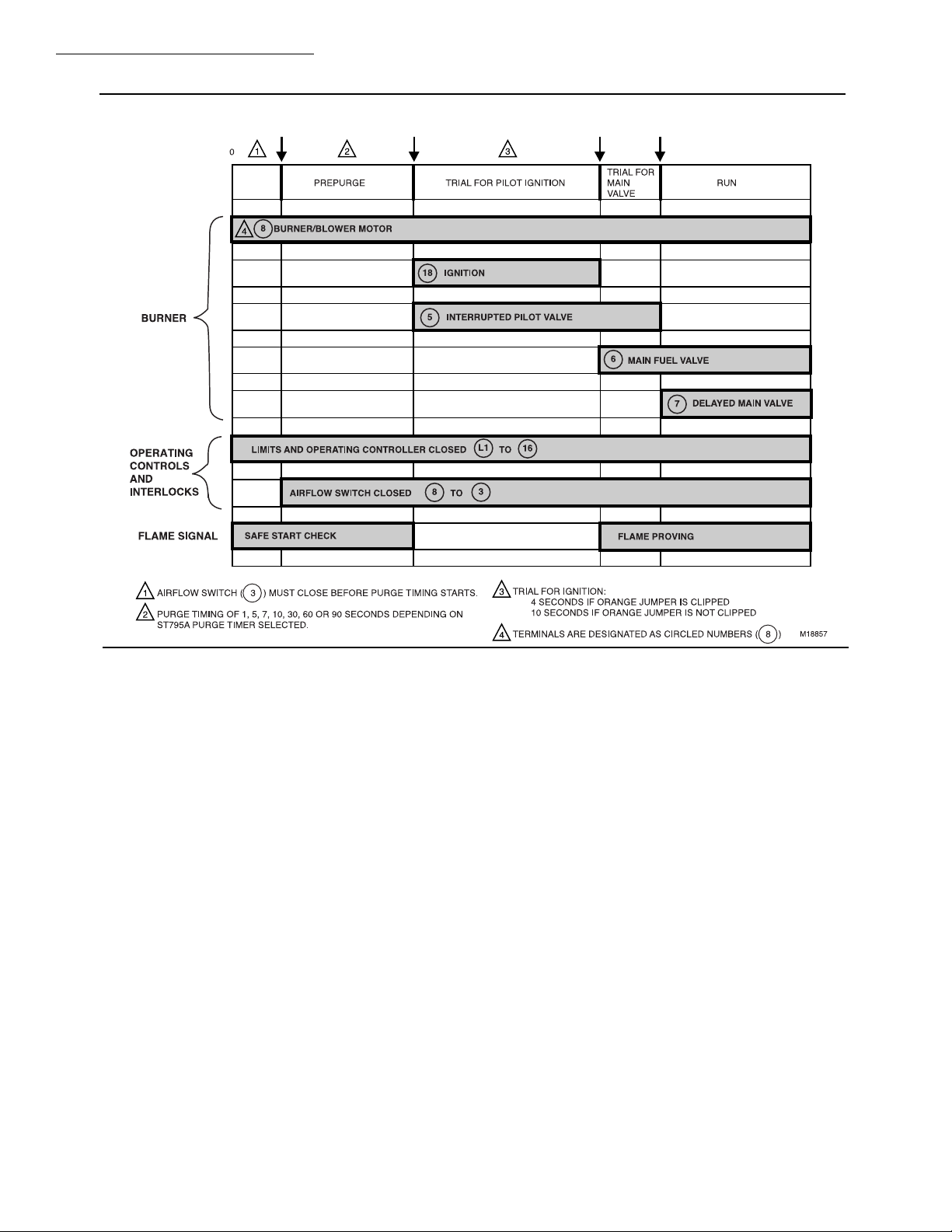
Fig. 4—Operating sequence for the R7795C,D with interrupted pilot.
The R7795C,D provides the following operational sequence when used with the appropriate flame detector. (See
Figs. 4 and 5.)
STANDBY
The R7795 Primary Control is ready to start up when the
burner controller closes (limits are closed).
NORMAL START-UP
1. With power applied (limits and controller closed, terminal L1 to 16, and no flame signal present), the 3K
relay pulls in and the burner motor (terminal 8) is energized.
2. As soon as the airflow switch closes (terminal 3 to
8), and with the RUN/TEST switch in the RUN position, the ST795A Prepurge Timer starts to time out (prepurge begins).
NOTE: The ST795A Prepurge Timer returns to zero any
time the airflow switch opens or the RUN/TEST switch
is moved to the TEST position. The prepurge restarts
when the airflow switch recloses or the RUN/TEST
switch is returned to the RUN position.
3. At the end of prepurge (ST795A timed out), the 1K
and 4K relays pull in, simultaneously energizing the ignition transformer (terminal 18) and the interrupted pilot
valve (terminal 5). This starts the ten or four second pilot
flame establishing period. Safety shutdown and lockout
will occur if presence of flame is not proven within:
•Ten seconds if the ORANGE jumper is not clipped.
• Four seconds if the ORANGE jumper is clipped.
If the RUN/TEST switch is moved to the TEST position during the pilot flame establishing period, the sequence is stopped in trial for pilot flame. The safety switch
heater is energized during this pilot flame establishing
period whenever flame is not present. Safety shutdown
and lockout will occur if the absence of flame exceeds
15 seconds (nominal).
4. MAIN FLAME IGNITION TRIAL
At the end of the pilot flame establishing period (ten or
four seconds), with pilot flame present, and the RUN/TEST
switch in the RUN position, the ignition transformer (terminal 18) is de-energized and the main valve (terminal 6) is
energized, starting the main flame ignition trial.
Ten seconds into the main flame ignition trial, the pilot
valve (terminal 5) is de-energized and the delayed main
valve (terminal 7) is energized. This completes the ten
second main flame ignition trial period.
The R7795 is now in the normal burner run mode of
operation and will remain so until an external command
directs it to do otherwise.
5. NORMAL SHUTDOWN
When the burner controller opens, the main valves
(terminals 6 and 7) and the burner/blower motor (terminal 8) are immediately de-energized. The R7795 goes into
the standby mode, terminating the operating cycle.
6
 Loading...