

Page 1
R7515C MacroCel
Controller
INSTALLATION INSTRUCTIONS
Warning: This equipment generates , uses, and can radiate radio frequency energy , and if not installed and used in accordance
with the Instructions Manual, may cause interference with r adio communication. It has been tested and found to comply with
the limits for a Class A computing device pursuant to Subpart J of Part 15 of FCC Rules, which are designed to provide
reasonable protection against such interference when operated in a commercial en vironment. Operation of this equipment in
a residential area is likely to cause interference, in which case, user at their own expense will be required to take whatever
measures may be required to correct the interference. Any unauthorized modification of this equipment may result in the
revocation of the owner's authority to continue its operation.
™
BEFORE INSTALLATION
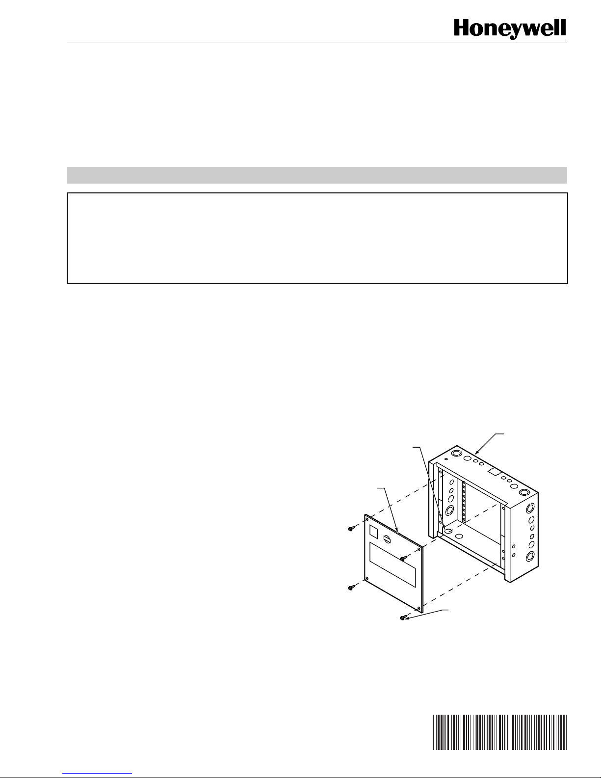
1. Unpack Door assembly and Subpanel from carton.
Check equipment and report any damage to a
Honeywell representative.
2. Unpack DeltaNet R7515C MacroCel Controller
(“MacroCel”) Card Cage Assembly (“Assembly”) from
carton. Check Assembly and report any damage to a
Honeywell representative.
3. Before installing, verify that Ring Cabinet is installed per
job drawings. (Refer to General Purpose Cabinet
Installation Instructions 95-7438 for details.)
4. Installation requires No. 10 x 1/2-in. sheet metal screws
(not supplied). Six screws are required for full-sized
subpanel; four for half-sized subpanel.
5. If application requires a tamper switch, use 14505159
Tamper Switch. The Tamper Switch includes a
4-40 x 5/8-in. machine screw.
6. Screw terminals are rated for 12 to 24 AWG solid or
stranded conductors.
7. Install in a controlled environment relatively free of
contaminants.
INSTALLATION
Install Subpanel
1. Position MacroCel subpanel in cabinet so all labeling
is visible.
2. Secure MacroCel subpanel in place with No. 10 x
1/2-in. sheet metal screws (Fig. 1 and 2).
NOTE: Subpanel must mount flat and should not
MacroCel
SUBPANEL
buckle anywhere.
LOWER OUTER
KNOCKOUTS
(4) RECOMMENDED
FOR EASE OF
INSTALLATION
HALF-SIZE
CABINET
® U.S. Registered Trademark
Copyright © 1998 Honeywell Inc. • All Rights Reserved
SIX NO. 10 X 1/2-IN.
MOUNTING SCREWS
Fig. 1. Mounting MacroCel subpanel in half-sized
ring cabinet.
C5691
95-7456-1
Page 2
R7515C MacroCel™ CONTROLLER
SIX NO. 10 X 1/2-INCH
MOUNTING SCREWS
MacroCel
SUBPANEL
LOWER OUTER KNOCKOUTS (4)
RECOMMENDED FOR EASE
OF INSTALLATION
FULL-SIZE
CABINET
C5690
Fig. 2. Mounting MacroCel subpanel in full-sized
ring cabinet.
Wire Subpanel to Interface Board
NOTES:
1. All wiring must conform to local codes,
ordinances, and regulations. Refer to job
drawings for details.
2. Use copper conductors only.
3. For 220/240V ac 50/60 Hz installations, verify
that voltage difference between any conductor
and earth ground does not exceed 150V ac.
4. An End-of-Line Resistor (EOLR) for use with the
C-NAP bus wiring is integral to the MacroCel
Subpanel Interface Board.
CAUTION
Verify that ac power is
power wiring terminal block (H-N-G) until system is
checked by a Honeywell Representative.
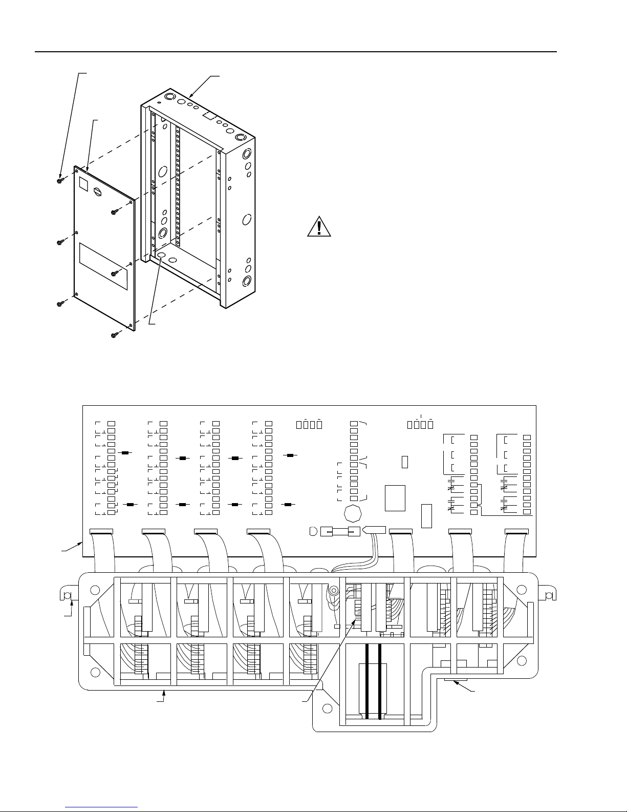
Wire the Subpanel as follows:
1. Connect field wiring to MacroCel subpanel Interface
Board or accessory devices per job drawings. Figure 3
shows MacroCel interface board terminal arrangement.
Figure 4 shows typical wiring.
not
connected to MacroCel
MacroCel
INTERFACE
BOARD
MOUNTING
TAB (2)
RTD
DIG
VOLT
RTD
DIG
VOLT
+10
+10
TB1
R1
D1
V1
R2
D2
V2
1
2
3
4
5
6
7
8
9
10
11
12
13
14
TERM V1
R1
TERM V2
R2
RTD
DIG
VOLT
RTD
DIG
VOLT
+10
+10
TB2
R3
D3
V3
R4
D4
V4
15
16
17
18
19
TERM V3
20
R3
21
22
23
24
25
26
TERM V4
27
R4
28
RTD
DIG
VOLT
RTD
DIG
VOLT
+10
+10
TB3
R5
D5
V5
R6
D6
V6
29
30
31
32
33
34
35
36
37
38
39
40
41
42
INPUTS
J1 J2 J3 J4
MacroCel
CARD CAGE
TERM V5
R5
TERM V6
R6
TB4
R7
RTD
D7
DIG
+10
V7
VOLT
R8
RTD
D8
DIG
+10
V8
VOLT
CONNECTOR J8
43
TB10
44
45
46
TERM V7
47
48
49
R7
50
51
52
53
54
TERM V8
55
R8
56
WALL MOD
24 VDC
+ +
5 7 5 8 5 9 6
0. 16A MAX
POWER
LED
CR2
CNAP
OUT IN
TB5
61
TO-1
0
COM1-2
COM3-4
TO-2
TO-3
TO-4
+
C1
F1
2A
O
62
T
U
R
T
63
I
P
64
A
U
C
T
65
66
67
T1
68
T2
2
4
69
T1
V
70
A
T2
C
71
T1
72
T2
TB8
POWER
24VAC T1
24VAC T2
+ +
7
7 7
TB9
3 7 4 5
6
0.16A MAX
A
JB1
1
1&2
IN
2
2&3
OUT
3
EOL
CNAP
BUS
ON
JACK
J8
J5
OFF
ANALOG
K1
K2
CNAP
BUS
S1
TB6
77
AO—1
78RET
79
AO—2
80
RET
ANALOG
81
AO—5
82
RET
83
A
84
C
85
B
86
A
87
C
B
88
OUTPUTS
J6 J7
SUBPANEL
SUPPORT (2)
TB7
89
AO—3
90RET
91
AO—4
92
RET
93
AO—4
94
RET
95
A
K3
K4
96
C
97
B
98
A
99
C
B
100
Fig. 3. MacroCel interface board terminal arrangement.
95-7456—1
C5611
2
Page 3

MacroCel
INTERFACE
BOARD
MOUNTING
TAB (2)
R7515C MacroCel™ CONTROLLER
C5611
123
4
5
678
9
10
111213
14
R1
RTD
D1
DIG
+10
+10
V1
VOLT
R2
RTD
D2
DIG
V2
VOLT
TB1
R1
R2
TERM V1
TERM V2
15161718192021222324252627
28
R3
RTD
D3
DIG
+10
+10
V3
VOLT
R4
RTD
D4
DIG
V4
VOLT
TB2
R3
R4
TERM V3
TERM V4
29303132333435363738394041
42
R5
RTD
D5
DIG
+10
+10
V5
VOLT
R6
RTD
D6
DIG
V6
VOLT
TB3
R5
R6
TERM V5
TERM V6
R7
RTD
D7
DIG
+10
+10
V7
VOLT
R8
RTD
D8
DIG
V8
VOLT
TB4
4748495051
52
53
545556
434546
44
J1
J2
J3
J4
R7
R8
TERM V7
TERM V8
57 58 59 6
0
+
+
24 VDC
TB10
C1
TO-1
TB5
65
66
67
686970717261636462
COM1-2
TO-2
TO-3
COM3-4
TO-4
T1
T2T1T2
T1
T2
O
U
TPU
T
T
R
I
A
C
2
4VA
C
POWER
LED
F1
2A+ CR2
TB8
POWER
24VAC T1
24VAC T2
J5
CNAP
BUS
JACK
ON
OFF
S1 AEOL
J6
J7 123 1&2
2&3
J8
3 74
5
+
+
CNAP
OUT IN
7
6
TB9
IN
OUT
AO—1
TB6
77
78
RET
ANALOG
79
80
AO—2
RET
AO—3
TB7
89
90
RET
ANALOG
91
92
AO—4
RET
MacroCel
CARD CAGE
JB1
INPUTS
WALL MOD
CONNECTOR J8
0. 16A MAX
CNAP
BUS
0.16A MAX
83
84
858687
88
ACB
ACB K1K2
OUTPUTS
959697
9899100
ACB
A
C
B
K3
K4
7
7
SUBPANEL
SUPPORT (2)
81
82
AO—5
RET
93
94
AO—4
RET
Fig. 4. MacroCel typical wiring.
3
95-7456—1
Page 4

R7515C MacroCel™ CONTROLLER
2. Connect C-NAP bus wiring to C-NAP terminal block on
MacroCel per job drawings (Fig. 5).
MacroCel
INTERFACE
BOARD
C5693
C-NAP
TERMINAL
BLOCK
CNAP
OUT IN
+ +
7
7
7
4 5
3
0.16 MAX
YEL
RED
RED
+
+
7
6
YEL
TB9
Fig. 5. Connecting C-NAP bus wiring to C-NAP terminal
block on MacroCel.
3. When required, activate the EOLR on the MacroCel
Subpanel Interface Board by placing the shorting bar in
Position 1-2 (Fig. 6A). Deactivate the EOLR by placing
the shorting bar in Position 2-3 (Fig. 6B).
A A
EOL EOL
A. EOLR "IN"
SHORTING BAR
1
1 & 2 IN
2
3
SHORTING BAR
2 & 3 OUT 2 & 3 OUT
B. EOLR "OUT"
1
1 & 2
2
3
IN
C5687
Fig. 6. MacroCel subpanel interface board EOLR
positions for activation (IN) and deactivation (OUT).
4. Connect line voltage to AC Input Block. Leave power to
MacroCel subpanel OFF until system is checked by a
Honeywell Representative.
5. Mount optional Tamper Switch on cabinet and wire per
job drawings (Fig. 7).
TAMPER
SWITCH
PLUNGER
LOCKNUT
PLUNGER
SCREW
RING
LOCK
WASHERS
FROM
TAMPER
SWITCH
SCREWS
FROM
DOOR
LATCH
Mount MacroCel Card Cage Assembly
NOTES:
1. Lower edge of Assembly is supported by two supports
on the Subpanel (Fig. 8). Do not force Assembly into
supports. If supports interfere with mounting Assembly,
gain proper clearance by using pliers to bend supports
outward slightly.
2. Two mounting tab screws are factory installed (started)
to aid in mounting the Assembly.
PREINSTALLED
MOUNTING TAB
SCREW (2)
INTEGRAL
SUPPORT
MacroCel
SUBPANEL
C5689
Fig. 8. Subpanel supports and preinstalled mounting
tab screws.
Mount the Assembly as follows:
1. Position mounting surface of Assembly flat against
Subpanel, aligning sides of Assembly with sides of
mounting silhouette and top of Assembly approximately
1 in. (25 mm) above top of mounting silhouette.
2. Slide Assembly down, simultaneously engaging lower
supports and preinstalled mounting tab screws.
3. Tighten screws to secure Assembly to Subpanel.
4. Connect input/output board ribbon cables and power
cable to Interface Board in sequential order as they
protrude from the Assembly. Connect farthest-left
ribbon cable connector to J1 on the Interface Board,
farthest right ribbon cable connector to J7 (Fig. 3).
AFTER INSTALLATION
1. Mount cabinet Door.
2. If applicable, adjust Tamper Switch screw (at end of
door switch plunger) so Tamper Switch activates when
door opens.
3. Close and lock Door.
DOOR
LATCH
Fig. 7. Mounting optional tamper switch.
By using this Honeywell literature, you agree that Honeywell will have no liability for any damages arising out of your
use or modification to, the literature. You will defend and indemnify Honeywell, its affiliates and subsidiaries, from and
against any liability, cost, or damages, including attorneys’ fees, arising out of, or resulting from, any modification to the
literature by you.
Home and Building Control
Honeywell Inc.
Honeywell Plaza
P.O. Box 524
Minneapolis MN 55408-0524
95-7456—1 T.M. 2-98
C6039
Home and Building Control
Honeywell Limited-Honeywell Limitée
155 Gordon Baker Road
North York, Ontario
M2H 3N7
Printed in U.S.A. on recycled
paper containing at least 10%
post-consumer paper fibers.
www.honeywell.com
 Loading...