

Page 1

R7184A,B,P,U
Interrupted Electronic Oil Primary
INSTALLATION INSTRUCTIONS
APPLICATION
The R7184A,B,P,U Interrupted Electronic Oil Primary is a
line voltage, safety rated, interrupted ignition oil primary
control for residential oil fired burners used in boiler s,
forced air furnaces and water heaters. The
R7184A,B,P, U used with a cad cell flame sensor,
operates an oil burner and optional oil valve. The primary
controls fuel oil, senses flame, controls ignition spark and
notifies a remote alarm circuit when in lockout.
The R7184 can be used with both hydronic and forced air
systems. When used with hydronic systems, line voltage
switching Aquastat® Controllers normally provide for the
starting and stopping of the combustion sequences. With
forced air systems, both mechanical and electron ic low
voltage thermostats control the starting and stopping of
the combustion process.
Some hydronic and forced air systems now require a
delayed valve-on and burner motor-off delay. The R7184
operates an oil valve that prevents the flow of oil when
the burner motor is running prior to combustion (delayed
valve-on) and when the burner motor is running after
combustion (burner motor-off delay).
The R7184 models are intended for use only on oil
burning appliances which do not require prep ur ge and
post-purge as a safety related function as defined in U L
296. The valve-on delay and burner motor-off delay in
this control are intended only to help establish draf t an d
reduce oil after-drip related problems.
FEATURES
Limited Recycle
This feature limits the number of recycle trials (for each
call for heat) to a maximum of three trials. If the flame is
lost three times and does not successfully satisfy a call
for heat, the R7184 locks out.
Pump Priming Cycle
T o facilitate purging air from the oil lines and filters, the
R7184 can be placed in a purge routine by pressing and
releasing the reset button during the safety check,
delayed valve-on , ignition or carry-over periods. The
lockout timing will be extended to 4 minutes and the
ignition set in the intermittent mode for this cycle only.
The R7184 automatically reverts to its labeled interrupted
and safety switch timing states. The pump primin g cycle
can only be entered if there have been no lockout
occurrences since the last successful heat call. To reset
the device so that the pump priming cycle can be
entered, press and hold the reset button for 30 seconds
until the LED flashes twice.
Disable Function
Pressing and holding the reset button will disabl e all
functions until the button is released. The R7184 will
restart at the beginning of the normal heat cycle on
safety check.
Limited Reset (Restricted Mode)
In order to limit the accumulation of unburned oi l in the
combustion area, the control can only be reset three
times. The reset count returns to zero each time a call for
heat is successfully completed.
To reset from restricted mode: Press and hold the reset
button for 30 seconds. When the LED flashes twice, the
device has reset.
SPECIFICATIONS
Models:
Table 1 lists the major features and the applicable w iring
diagram numbers for the R7184.
Timing:
Safe Start Check: 5 seconds (approximately).
Valve-on Delay: 15 seconds.
Burner motor-off Delay: 0, 2, 4, or 6 minutes, field-
selectable using DIP switch positions 1 and 2.
NOTE: For universal R7184U model, valve-on delay
and burner motor-off delay timings can be
enabled (values as listed) or disabled (values
are zero) in the field using DIP switch position 3.
Lockout: 15, 30 or 45 seconds (factory-programmed ).
Recycle: 60 seconds (fixed).
Ignition Carryover: 10 seconds (fixed).
® U.S. Registered Trademark
Copyright © 2000 Honeywell Inc. • All Rights Reserved
69- 1233- 2
Page 2
R7184A,B,P,U INTERRUPTED ELECTRONIC OIL PRIMARY
Electrical Ratings:
Inputs:
Voltage: 102 to 132 Vac, 120 Vac nominal.
Current: 100 mA plus burner motor, valve and ignitor
loads.
Frequency: 60 Hz.
Outputs:
Relay Contacts:
Burner: 120 Vac, 10 full load amperes (FLA),
60 locked rotor amperes (LRA).
Valve: 120 Vac, 1A.
Ignitor: 120 Vac, 360 VA.
Alarm: 30 Vac, 2A.
Thermostat Current Available: 100 mA.
Table 1. R7184 Models.
Model
R7184A None None None 3,4,5 Yes
R7184B 15 None None 3,6,7
R7184P
R7184U Selectable 0 or 15 Selectable 0 or
a
Some select models may have a delay enable/disable swit ch.
b
Standard timings. Other timing may be availa ble on select mo dels.
c
Select models are provided with a T-T jumper which can be disa bled by cutting with a pair of side-cutting pliers.
Valve-on delay
a
15
(sec)
Burner motor-off
delay (min)
b
0/2/4/6
b
0,2,4,6
NOTE: Reduce burner FLA rating by Ignitor load. For
example, if the ignitor draws 3A (120 Vac, 360
VA), reduce the burner motor FLA to 7A.
Environmental Ratings:
Operating Ambient Temperature: -40°F (-40°C) to
+147°F (+64°C).
Shipping Temperature: -20°F (-29°C) to +150°F (+66°C).
Humidity: 90% relative humidity at 95°F (9 3°C)
noncondensing.
Approvals:
Underwriters Laboratories Inc.: Recogni zed.
Canadian Underwriters Laboratories Inc.
Alarm
Contacts
Optional 3,6,7 Yes
Yes 3,6,7 Yes
Typical Wiring Diagram
Fig. Reference No.
Thermostat
Terminal s T- T
c
Yes
INSTALLATION
When Installing this Product...
Read these instructions carefully. Failure to follow
1.
instructions can damage product or cause a
hazardous condition.
Check ratings given in these instructions and on
2.
product to make sure product is suitable for your
application.
Make sure installer is a trained, experienced
3.
service technician.
Use these instructions to check out product
4.
operation after installation.
R7184S7184
BURNER
WARNING
Electrical Shock Hazard.
Can cause serious injury or death.
Disconnect power supply before beginning
installation to prevent electrical shock or
equipment damage.
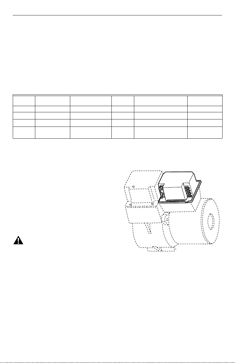
Location
Mount on a 4 in. by 4 in. junction box, directly on
1.
the main burner or inside the appliance cabinet. In
replacement applications, mount in the same
location as the old control. See Fig. 1. Make sure
the operating temperatures are within the ambient
temperature range (see Specifications section).
Before mounting the control, make line voltage
2.
connections as shown in Fig. 2 through 7. Splice
lines with solderless connectors. Do not exceed
load ratings shown on the device label.
If necessary, use the control as a template to mark
3.
and drill new mounting holes.
Mount using No. 6 screws (obtained locally).
4.
69-1233—2 2
M17180A
Fig. 1. Mounting R7184 on junc tion box.
WIRING
Make sure wiring complies with all local codes and
1.
ordinances.
After mounting, make low voltage connections to
2.
the screw terminals (see Fig. 2 through 7).
Strip leads 3/8 in. (10 mm) and insert under
3.
terminal screw. See Fig. 1.
Connect thermostat leads to T-T.
4.
Switch Settings
Figure 8 and Table 2 provide the switch settings for the
R7184U.
Page 3

R7184A,B,P,U IN TE RRUPTED ELECTRONIC OIL PRIMARY
CHECKOUT
Start System
WARNING
Fire Hazard.
Can cause serious injury or death.
Make sure combustion chamber is free of oil
and/or oil vapor before starting system.
INTERRUPTED
IGNITOR
INTERMITTENT
BURNER MOTOR
L1
L2
LIMIT
VALVE
Fig. 2. Wiring terminals.
Open hand valve in oil supply line.
1.
Make sure system is powered. Check circuit
2.
breaker or fuse and close system switch, if
provided.
Set thermostat to call for heat.
3.
Make sure burner lights and operates until call for
4.
heat ends.
Check Safety Features
Safe Start
Place a jumper across cad cell terminals.
1.
Follow procedure to turn on burner. Burner must
2.
not start, indicator light turns on and control
remains in Idle Mode.
Simulate flame failure:
Follow procedure to turn on burner.
1.
Close hand valve in oil supply line.
2.
Device enters recycle mode.
3.
Device tries to restart system after approximately
4.
60 seconds.
Safety switch locks out approximately in safety
5.
switch timing indicated on label. Indicator light
flashes at 1 Hz rate. Ignition and motor stop and oil
valve closes.
CAD CELL
M16453A
THERMOSTAT
R
W
TO
REMOTE
ALARM
CIRCUIT
LEGEND:
1
2
CIRCULATION
PUMP
R7184
LIMIT
T
T
JUMPER
2
POWER SUPPLY. PROVIDE DISCONNECT MEANS
AND OVERLOAD PROTECTION AS REQUIRED.
OPTIONAL FEATURE ON SELECT MODELS.
L2
BURNER MOTOR
INTERRUPTED
IGNITOR
INTERMITTENT
VALVE
CAD
ALARM
CELL
SCREW TERMINAL
L8148A,C
C1
AQUASTAT®
CONTROLLER
C2
L1
JUNCTION
BOX
B2
B1
T
T
BURNER
MOTOR
IGNITOR
VALVE
CAD
CELL
1/4 IN. QUICK CONNECT TERMINAL
M17182B
Fig. 3. Wiring for typical oil-fired bo il er.
HOT
L1
(HOT)
L2
1
L1
L2
3
M17183B
T8600
RC
G
Y
R
W
TO
REMOTE
ALARM
2
CIRCUIT
LEGEND:
1
POWER SUPPLY. PROVIDE DISCONNECT MEANS
AND OVERLOAD PROTECTION AS REQUIRED.
2
OPTIONAL FEATURE ON SELECT MODELS.
VALVE MAY BE ADDED AS SHOWN.
3
Fig. 4. Typical wiring diagram for 24 Vac thermostat
and R7184 for an oil-fired forced air system.
FAN RELAY
R7184
T
L1
T
L2
BURNER
MOTOR
INTERRUPTED
IGNITOR
INTERMITTENT
CAD
CELL
ALARM
SCREW TERMINAL
COOLING
CONTROL
LIMIT
VALVE
BURNER
MOTOR
IGNITOR
CAD
CELL
JUNCTION
BOX
1/4 IN. QUICK CONNECT TERMINAL
L1
L2
1
1
3 69-1233—2
Page 4

R7184A,B,P,U INTERRUPTED ELECTRONIC OIL PRIMARY
JUMPER
TO
REMOTE
ALARM
CIRCUIT
LEGEND:
1
POWER SUPPLY. PROVIDE DISCONNECT MEANS
AND OVERLOAD PROTECTION AS REQUIRED.
OPTIONAL FEATURE ON SELECT MODELS.
2
3
VALVE MAY BE ADDED AS SHOWN.
Fig. 5. Typical wiring diagram for line voltage
Aquastat® thermostat and R 7184 for an oil burner
T8600
RC
G
Y
R
W
R7184
T
T
BURNER
MOTOR
INTERRUPTED
IGNITOR
INTERMITTENT
ALARM
2
SCREW TERMINAL
R7184
T
T
L1
L2
CAD
CELL
FAN RELAY
L1
LIMIT
L2
LINE VOLTAGE
THERMOSTAT
OR AQUASTAT®
CONTROL
VALVE
BURNER
MOTOR
IGNITOR
CAD
CELL
JUNCTION
BOX
1/4 IN. QUICK CONNECT TERMINAL
system.
COOLING
CONTROL
LIMIT
LIMIT
3
M17184B
1
L1
HOT
L2
1
L1
HOT
L1
(HOT)
L2
L2
1
JUMPER
TO
REMOTE
ALARM
CIRCUIT
LEGEND:
1
POWER SUPPLY. PROVIDE DISCONNECT MEANS
AND OVERLOAD PROTECTION AS REQUIRED.
2
OPTIONAL FEATURE ON SELECT MODELS.
Fig. 7. Typical wiring diagram for line voltage
Aquastat® thermostat and R718 4B,P,U for valve-on
delay/burner motor-off delay oil burner system.
Simulate ignition failure:
Follow starting procedure to turn on burner, but do
1.
not open oil supply hand valve.
Observe that safety switch locks out approximately
2.
within safety switch timing as indicated on the
label. Indicator light flashes at 1 Hz rate. Ignition
and motor stop and oil valve closes.
OPERATION
R7184
T
T
VALVE
BURNER
MOTOR
INTERRUPTED
IGNITOR
INTERMITTENT
ALARM
2
SCREW TERMINAL
LIMIT
L2
L1
CAD
CELL
LINE VOLTAGE
THERMOSTAT
OR AQUASTAT®
CONTROL
OIL
VALVE
BURNER
MOTOR
IGNITOR
CAD
CELL
JUNCTION BOX
1/4 IN. QUICK CONNECT TERMINAL
LIMIT
M17186A
HOT
1
L1
L2
VALVE
BURNER
MOTOR
INTERRUPTED
IGNITOR
INTERMITTENT
TO
REMOTE
ALARM
2
CIRCUIT
LEGEND:
1
POWER SUPPLY. PROVIDE DISCONNECT MEANS
AND OVERLOAD PROTECTION AS REQUIRED.
2
OPTIONAL FEATURE ON SELECT MODELS.
Fig. 6. Typical wiring diagram for 24 Vac thermostat
and R7184 for valve-on delay/bu r ner mo t or off oi l
CAD
ALARM
CELL
SCREW TERMINAL
burner system.
OIL
VALVE
BURNER
MOTOR
IGNITOR
CAD
CELL
JUNCTION
BOX
1/4 IN. QUICK CONNECT TERMINAL
M17185A
The R7184 is a microprocessor-based contr ol. The
indicator light provides diagnostic information for lockout,
recycling and patented cad cell status. There is a manual
reset button to exit the lockout mode and enter the idle
mode. Operation is shown in Table 4.
TROUBLESHOOTING AND MAINTENANCE
IMPORTANT:
Due to the potential hazard of line voltage, only
a trained, experienced service technician
should perform the troubleshooting procedure.
This control contains no field-serviceable parts.
Do not attempt to take it apart. Replace entire
control if operation is not as described.
To completely troubleshoot an oil burner ins tal la ti on,
check the burner and oil primary control for proper
operation and condition.
The indicator light on the oil primary control provid es
lockout, recycle and cad cell indications as follows:
69-1233—24
Page 5

R7184A,B,P,U IN TE RRUPTED ELECTRONIC OIL PRIMARY
Flashing at 1 Hz (1/2 second on, 1/2 second off):
1.
system is locked out or in restricted mode.
Flashing at 1/4 Hz (2 seconds on, 2 seconds off):
2.
control is in recycle mode.
VALVE ON DELAY TIME: 15 SEC. (FIXED)
BURNER MOTOR OFF DELAY TIME:
ON
ON
ON
1
1
2
2
0 MIN. 2 MIN.
(SHADED AREA IS SWITCH HANDLE POSITION)
1
4 MIN.
ON
2
6 MIN.
1
2
DELAY TIMES:
ENABLED DISABLED
33
M17535
On: cad cell is sensing flame.
3.
Off: cad cell is not sensing flame.
4.
Fig. 8. Switch settings for burner-o ff delay times.
Table 2. Switch Settings and Delays.
Delay Timings DIP Switch Settings
Burner Motor-Off Delay
Valve-On
Delay
(seconds)
(minutes)
R7184U R7184P R7184U R7184P
S-1 S-2
S-3 Enable/Disable
00— XX Off +
15 0 0.5 Off Off On +
15 2 2 Off On On +
15 4 4 On Off On +
15 6 8 On On On +
X = Don’t Care.
+ = S-3 not provided on R7184P models.
Check the piping to the oil tank.
Cad Cell Resistance Check
For proper operation it is important that the cad cell
resistance is below 1600 ohms. During a normal call for
heat, once the control has entered the Run mode, press
and release the reset button. Indicator light will flash 1 to
4 flashes. See Table 3 for equivalent cad cell resistance.
Table 3. Cad cell resistance when sensing flame.
Flashes Cad Cell Resistance in ohms
1 Less than 400
2 More than400 and less than 800
6.
Check the oil nozzle, oil supply and oil filter.
7.
Check Oil Primary Control
If the trouble is not in the burner or ignition hardwar e,
check the oil primary control by using the following
equipment:
Screwdriver.
1.
Voltmeter (0 to 150 Vac).
2.
Insulated jumper wire with both ends stripped.
3.
3 More than 800 and less than 1600
4 More than 1600 and less than 5000
Preliminary Steps
Check wiring connections and power supply.
1.
Make sure power is on to the controls.
2.
Make sure limit control is closed.
3.
Check contacts between ignitor and the
4.
electrodes.
Check the oil pump pressure.
5.
WARNING
Electrical Shock Hazard.
Can cause s er ious injury or death.
Troubleshoot with the system powered. Be
careful to observe all precautions to prevent
electrical shock or equipment damage.
Refer to Table 4 for further troubleshooting
information.
5 69-1233—2
Page 6

R7184A,B,P,U INTERRUPTED ELECTRONIC OIL PRIMARY
Table 4. R7184 Operation.
External Ac tion R7184 Action
Power applied to control. Internal safety check conducted. If no light or flame is detected and all internal
Thermostat or Aquastat
Control calls for heat.
Call for heat is satisfied.
Reset button pushed two
times without device
completing a call for heat.
conditions are correct, control enters Idle mode.
®
Shorts across T-T terminals (on as call for heat) in warm air system and/ or
1.
provides power to limit terminals in hydronic system.
Safety Period (4 seconds) internal and external check for flame or light. If flame or
2.
light is detected, control remains in Idle mode.
When flame or light is not present:
3.
a. R7184A,U (if valve-on delay is disabled) will apply power to the burner motor
and ignitor.
b. R7184B,P,U (if valve-on delay is enabled) will apply power to the burner motor
and ignitor, enter/complete valve-on delay period and then apply power to the
valve.
Control enters Trial for Ignition period.
4.
a. Monitors burner for flame.
b. When flame is not detected:
(1) Enters lockout mode (after lockout ti m e of 15, 30 or 45 seconds) .
(2) Shuts off valve, ignitor and burner motor.
(3) Flashes indicator light at 1 Hz (1/2 second on, 1/2 second off).
(4) Depress reset button to return to power up sequence.
c. When flame is detected, Carry-Over period begins:
Control enters Ignition Carry-Over period (cont inues to spark for 10 to 30
5.
seconds).
a. Turns on indicator light.
b. If flame is lost and lockout time has not expired, R7184 returns to Trial for
Ignition period.
c. If flame is lost and lockout time has expired, R7184 enters Recycle Mode.
Carry-Over time expires; ignitor turns off.
6.
Enters Run Mode:
7.
a. Flame is monitored until call for heat ends or flame is lost. If flame is lost:
(1) Control enters Recycle Mode.
(2) Recycle time starts (60 seconds).
(3) Burner and valve are turned off.
(4) Indicator light flashes at 1/4 Hz (2 seconds on, 2 seconds off).
(5) Returns to Idle mode at end of Recycle mode.
R7184A,U (if burner motor-off delay is disabled):
1.
a. Burner motor and oil valve shut off.
b. Indicator light turns off.
R7184B,P,U (if burner motor-off delay is enabled):
2.
a. Oil valve shuts off.
b. Burner motor runs for selected burner moto r-off delay.
c. Bu rner motor turns off.
d. Device returns to Idle mode.
R7184 enters Restricted mode.
1.
Indicator light flashes at 1Hz (1/2 second on, 1/2 second off).
2.
Reset device by pressing and holding reset button for a minimum of 30 seconds.
3.
Table 5. Troubleshooting Information .
Procedure Status Correct ive Actions
Condition: Burner does not start w ith a cal l for heat .
1. Check that limit switches are closed
and contacts are clean.
2. Check for line voltage power at the oil
primary control. Voltage should be 120
Vac.
3. Check indicator light with burner off,
no call for heat (no flame).
——
——
Indicator light is on. Cad cell or controller is defective, sees external light
or connections are shorted. Go to step 4.
Indicator light is off. Go to step 5.
69-1233—26
Page 7

R7184A,B,P,U IN TE RRUPTED ELECTRONIC OIL PRIMARY
Table 5. Troubleshooting Information (Continued).
Procedure Status Correct ive Actions
4. Shield cad cell from external light. Indicator light turns
5. On warm air systems, jumper
thermostat (T to T) terminals on R7184.
(On hydronic systems jumper Limit
terminal and L1 of R7184.)
IMPORTANT:
First remove one thermostat
lead.
Condition: Burner starts, then locks out on safety with indicator light flashing at 1 Hz rate (1/2 second on, 1/2
second off)
1. Check that limit switches are closed
and contacts are clean.
2. Check for line voltage power at the
oil primary control. Voltage should be
120 Vac.
3. Check indicator light with burner off,
no call for heat (no flame).
4. Shield cad cell from external light. Indicator light turns
.
off.
Indicator light stays
on.
Burner starts. Trouble in thermostat or limit circuit. Check
Burner does not start. • Disconnect line voltage pow er and open line
––
––
Indicator light is on. Cad cell or controller is defective, sees external light
Indicator light is off. Go to step 5.
off.
Indicator light stays
on.
Eliminate external light source or permanently shield
cad cell.
• Replace cad cell with new cad cell and recheck.
• If indicator light does not turn off, remove cad cell
leadwires from R7184 and recheck.
• If indicator light turns off, replace cad cell bracket
assembly. Refer to TRADELINE® Catalog for
bracket part numbers.
• If indicator light does not turn off, replace
controller.
thermostat or limit wiring connections.
switch.
• Check all wiring connections.
• Tighten any loose connections and recheck.
• If burner does not start, replace R7184.
or connections are shorted. Go to step 4.
Eliminate external light source or permanently shield
cad cell.
•
Replace cad cell with new cad cell and
recheck.
•
If indicator light does not turn off, remove cad
cell leadwires from R7184 and recheck.
•
If indicator light turns off, replace cad cell
bracket assembly. Refer to TRADELINE
®
catalog for bracket part numbers.
•
If indicator light does not turn off, replace
controller.
5. On warm air systems, jumper
thermostat (T to T) terminals on R7184.
(On hydronic systems, jumper Limit
terminal and L1 of R7184.)
IMPORTANT:
First remove one thermostat lead.
Burner starts. Trouble is in thermostat or limit circuit. Check
Burner does not start.
thermostat or limit wiring connections.
•
Disconnect line voltage power and open line
switch.
•
Check all wiring connections.
•
Tighten any loose connections and recheck.
•
If burner does not start, replace R7184.
Condition: Burner starts then locks out on safety with indicator light fl ashing at 1 Hz rate (1/2 second on, 1/2
second off)
6. Reset oil primary control by pushing
in and releasing red reset button.
Indicator light stops
flashing.
Indicator light
continues to flash at
a
1 Hz rate
.
Go to step 7.
Verify that control is not in restricted mode (see
footnote a). If not in restricted mode, replace R7184.
7 69-1233—2
Page 8

R7184A,B,P,U INTERRUPTED ELECTRONIC OIL PRIMARY
Table 5. Troubleshooting Information (Continued).
Procedure Status Correct ive Actions
7. Listen for spark after burner turns on
(after a 2 second delay.
Ignition is off. Spark ignitor could be defective. Check for line
Ignition is on. Go to step 8.
Ignition is on, but no
oil is being sprayed
into the combustion
chamber.
8. Check indicator light after flame is
established, but before oil primary
control locks out.
9. Check cad cell sighting for view of
flame.
• Disconnect line voltage power and
open line switch.
• Unplug cad cell and clean cad cell
face with soft cloth. Check sighting
for clear view of flame. Place cad cell
back in socket.
• Reconnect line voltage power and
close line switch.
• Start burner.
10. Check cad cell.
• Disconnect line voltage power and
open line switch.
• Remove exi sting cad ce ll an d repl ace
with new cad cell.
• Disconnect all wires from thermostat
terminals to be sure there is no call
for heat.
• Reconnect line voltage power and
close line switch.
• Expose new cad cell to bright light,
such as a flashlight.
11. Check cad cell bracket assembly.
• Disconnect line voltage power and
open line switch.
• Remove cad cell wires from quickconnect connectors on the R7184
and leave control leadwires open.
• Apply power to device.
• Place jumper across cad cell
terminals after burner motor turns on.
Indicator light is on
until the control locks
out and starts flashing
during lockout.
Indicator light stays
off.
Burner locks out. Go to step 10.
Burner keeps running. System is okay.
Indicator light is on. Place control back on burner. Go to step 6.
Indicator light is off. Go to step 11.
Indicator light is on. Replace cad cell bracket assembly. Refer to
Indicator light is off. Replace R7184.
voltage at ignitor terminals. If line voltage is present,
replace R7184.
Wait for Valve On Delay to complete (R7184B,P, and
U). Check oil valve, oil valve wiring, pump and oil
supply.
Replace R7184.
Go to step 9.
TRADELINE® Catalog for bracket part numbers.
Home and Building Control Home and Building Control
Honeywell Inc. Honeywell Limited-Honeywell Limitée
Honeywell Plaza 155 Gordon Baker Road
P.O. Box 524 North York, Ontario
Minneapolis, MN 55408-0524 M2H 3N7
69-1233—2 G.R. Rev. 5-00 www.honeywell.com
Printed in U.S.A. on recycled
paper containing at least 10%
post-consumer paper fibers.
 Loading...