

Page 1
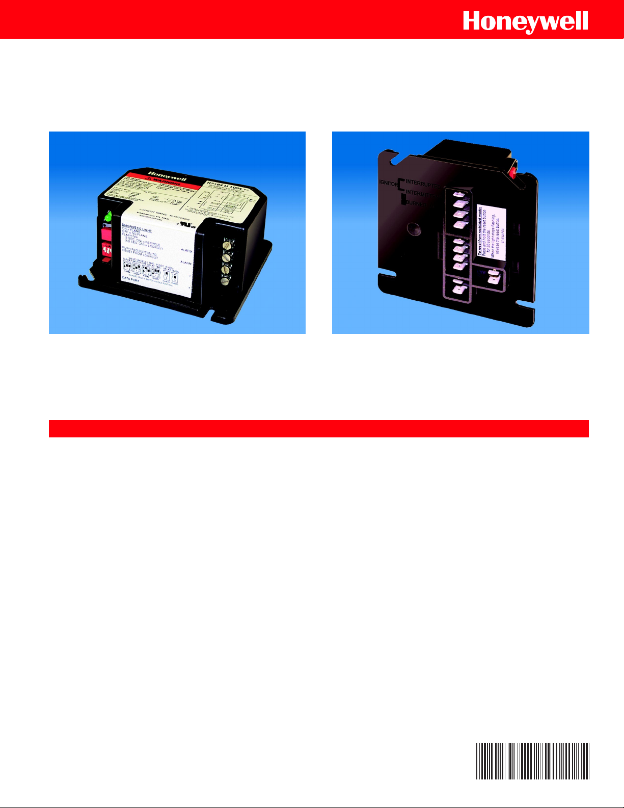
R7184
Interrupted Electronic Oil Primary
The new R7184 features interrupted ignition and valve-on delay with selectable
blower-off delay timings on selected models.
FEATURES
■ Compatible with hydronic and forced air applications.
■ Patented cad cell resistance readout.
■ Available in 15- and 30-second lockout times.
■ Safe start check.
■ Status indicator light monitors burner flame status and
system lockout.
■ Uses proven flame detection and monitoring systems.
■ Optional valve-on delay, blower-off delay models.
– 15 second or selectable 0 or 15 second valve-on
delay.
– Zero time or selectable 0-, 2-, 4-, 6-minute blower-off
delay.
– Oil valve control.
– Compatible with power venters without integral
timers.
■ Oil-resistant plastic cover for electronics.
■ Mounts on standard 4 in. by 4 in. junction box, directly
on main burner or inside appliance cabinet.
■ UL Component Recognition.
■ CUL Component Recognition.
Copyright © 1999 Honeywell Inc. • All Rights Reserved
68-3033
Page 2
R7184 INTERRUPTED ELECTRONIC OIL PRIMARY
SPECIFICATIONS R7184
Models:
Table 1 lists the major features of the R7184 models.
Table 1. R7184 Models.
Model Valve-On Delay (sec) Blower-Off Delay (min) Alarm Contacts Thermostat Terminals T-T
R7184A No No No Ye s
R7184B Ye s No No jumpered
R7184P Yes Selectable No Yes
R7184U Selectable Selectable Yes Yes
Timing
Valve-on Delay: 0 or 15 seconds.
Blower-off Delay: 0, 2, 4, or 6 minutes, field-selectable using
DIP switch positions 1 and 2.
NOTE: For universal R7184U model, valve-on delay and
blower-off delay timings can be enabled or disabled
(values are zero) in the field using DIP switch
position 3. See installation instructions, form 69-1233.
Electrical Ratings:
Inputs:
Voltage: 102 to 132 Vac, 120 Vac nominal.
Current: 50 mA plus burner motor, valve and ignitor loads.
Frequency: 60 Hz.
Outputs:
Relay Contacts:
Burner: 120 Vac, 10 full load amperes (FLA), 60 locked rotor
amperes (LRA).
NOTE: Reduce burner motor FLA by ignitor load. For
example, the ignitor listed below draws a maximum
of 3A (120 Vac, 360 VA). Reduce the burner motor
FLA to 7A.
Valve: 120 Vac, 1A.
Ignitor: 120 Vac, 360 VA.
Alarm: 30 Vac, 2A.
Thermostat Current Available: 100 mA.
Environmental Ratings:
Operating Ambient Temperature:
-40°F (-40°C) to +150°F (+66°C).
Shipping Temperature: -20°F (-29°C) to +150°F (+66°C).
Humidity: 90% relative humidity at 95°F (35°C) noncondensing.
Approvals:
Underwriters Laboratories Inc. Component Recognized.
Canadian Underwriters Laboratories Inc. Component
Recognized.
OPERATION
The R7184 is a microprocessor-based control. The LED offers
diagnostic information for lockout, recycling and patented cad
cell status. There is a manual reset button to exit the lockout
state and enter the idle state.
TYPICAL CONNECTIONS
Fig. 1 through 4 show typical R7184 connections.
NOTE: When installing the R7184 with a line voltage
thermostat, connect the line voltage thermostat in
series with the limit controller.
R7184
JUMPER
ALARM
2
LEGEND:
1
POWER SUPPLY. PROVIDE DISCONNECT MEANS
AND OVERLOAD PROTECTION AS REQUIRED.
2
OPTIONAL FEATURE ON SELECT MODELS.
L1
T
LIMIT
T
L2
VALVE
BURNER
MOTOR
IGNITOR
CAD
CELL
SCREW TERMINAL
LINE VOLTAGE
THERMOSTAT
OR AQUASTAT
CONTROL
OIL VALVE
BURNER
MOTOR
IGNITOR
JUNCTION BOX
1/4 IN. QUICK CONNECT TERMINAL
®
CAD CELL
LIMIT
M16297
1
L1
(HOT)
L2
68-3033
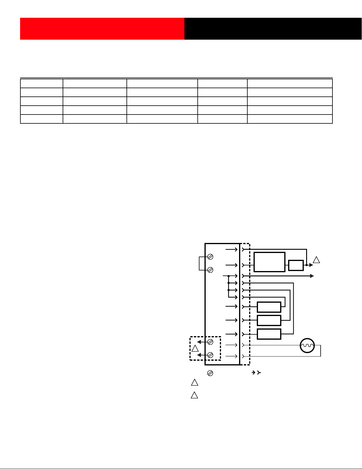
Fig. 1. Typical connection for line voltage thermostat
and R7184B,P,U for valve-on delay/blower-off delay
oil burner system.
2
Page 3

R7184 INTERRUPTED ELECTRONIC OIL PRIMARY
JUMPER
2
LEGEND:
1
POWER SUPPLY. PROVIDE DISCONNECT MEANS
AND OVERLOAD PROTECTION AS REQUIRED.
2
OPTIONAL FEATURE ON SELECT MODELS.
R7184
T
T
L2
BURNER
MOTOR
IGNITOR
CAD
ALARM
CELL
SCREW TERMINAL
LINE VOLTAGE
L1
THERMOSTAT
OR AQUASTAT
CONTROL
BURNER
MOTOR
IGNITOR
JUNCTION BOX
1/4 IN. QUICK CONNECT TERMINAL
®
LIMIT
CAD CELL
M16298
1
L1
(HOT)
L2
Fig. 2. Typical connection for line voltage thermostat and
R7184A for oil burner system.
T8600
RC
G
Y
R
W
LEGEND:
R7184
ALARM
2
SCREW TERMINAL
T
T
L1
LIMIT
L2
VALVE
BURNER
MOTOR
IGNITOR
CAD
CELL
FAN RELAY
COOLING
TRANSFORMER
COOLING
CONTROL
LIMIT
OIL VALVE
BURNER
MOTOR
IGNITOR
CAD CELL
JUNCTION BOX
1/4 IN. QUICK CONNECT TERMINAL
L1
(HOT)
L2
1
1
L1
(HOT)
L2
T8600
RC
G
Y
R
W
2
LEGEND:
1
POWER SUPPLY. PROVIDE DISCONNECT MEANS
AND OVERLOAD PROTECTION AS REQUIRED.
2
OPTIONAL FEATURE ON SELECT MODELS.
R7184
T
T
BURNER
MOTOR
IGNITOR
ALARM
SCREW TERMINAL
L2
L1
CAD
CELL
FAN RELAY
COOLING
CONTROL
JUNCTION BOX
1/4 IN. QUICK CONNECT TERMINAL
COOLING
TRANSFORMER
LIMIT
BURNER
MOTOR
IGNITOR
CAD CELL
L1
(HOT)
L2
M16299
1
1
L1
(HOT)
L2
1
POWER SUPPLY. PROVIDE DISCONNECT MEANS
AND OVERLOAD PROTECTION AS REQUIRED.
2
OPTIONAL FEATURE ON SELECT MODELS.
M16300
Fig. 4. Typical connection for 24 Vac thermostat
and R7184B,P,U for valve-on delay/blower-off
delay oil burner system.
Fig. 3. Typical connection for 24 Vac thermostat and
R7184A for oil burner system.
3
68-3033
Page 4

R7184 INTERRUPTED ELECTRONIC OIL PRIMARY
Home and Building Control
Honeywell Inc.
Honeywell Plaza
P.O. Box 524
Minneapolis, MN 55408-0524
68-3033 G.R. 1-99
68-3033
Home and Building Control
Honeywell Limited-Honeywell Limitée
155 Gordon Baker Road
North York, Ontario
M2H 3N7
Printed in U.S.A. on recycled
paper containing at least 10%
post-consumer paper fibers.
4
www.honeywell.com
 Loading...